EP2881166A2 - Blasenerzeugende querflussvorrichtung und blasenerzeugungsverfahren - Google Patents
Blasenerzeugende querflussvorrichtung und blasenerzeugungsverfahren Download PDFInfo
- Publication number
- EP2881166A2 EP2881166A2 EP13827078.0A EP13827078A EP2881166A2 EP 2881166 A2 EP2881166 A2 EP 2881166A2 EP 13827078 A EP13827078 A EP 13827078A EP 2881166 A2 EP2881166 A2 EP 2881166A2
- Authority
- EP
- European Patent Office
- Prior art keywords
- pressure
- liquid
- dispersed
- fluid
- flow
- Prior art date
- Legal status (The legal status is an assumption and is not a legal conclusion. Google has not performed a legal analysis and makes no representation as to the accuracy of the status listed.)
- Withdrawn
Links
Images

Classifications
-
- B—PERFORMING OPERATIONS; TRANSPORTING
- B01—PHYSICAL OR CHEMICAL PROCESSES OR APPARATUS IN GENERAL
- B01F—MIXING, e.g. DISSOLVING, EMULSIFYING OR DISPERSING
- B01F23/00—Mixing according to the phases to be mixed, e.g. dispersing or emulsifying
- B01F23/20—Mixing gases with liquids
- B01F23/23—Mixing gases with liquids by introducing gases into liquid media, e.g. for producing aerated liquids
- B01F23/231—Mixing gases with liquids by introducing gases into liquid media, e.g. for producing aerated liquids by bubbling
- B01F23/23105—Arrangement or manipulation of the gas bubbling devices
- B01F23/2312—Diffusers
- B01F23/23124—Diffusers consisting of flexible porous or perforated material, e.g. fabric
- B01F23/231241—Diffusers consisting of flexible porous or perforated material, e.g. fabric the outlets being in the form of perforations
- B01F23/231242—Diffusers consisting of flexible porous or perforated material, e.g. fabric the outlets being in the form of perforations in the form of slits or cut-out openings
-
- B—PERFORMING OPERATIONS; TRANSPORTING
- B01—PHYSICAL OR CHEMICAL PROCESSES OR APPARATUS IN GENERAL
- B01F—MIXING, e.g. DISSOLVING, EMULSIFYING OR DISPERSING
- B01F23/00—Mixing according to the phases to be mixed, e.g. dispersing or emulsifying
- B01F23/20—Mixing gases with liquids
- B01F23/23—Mixing gases with liquids by introducing gases into liquid media, e.g. for producing aerated liquids
- B01F23/232—Mixing gases with liquids by introducing gases into liquid media, e.g. for producing aerated liquids using flow-mixing means for introducing the gases, e.g. baffles
- B01F23/2323—Mixing gases with liquids by introducing gases into liquid media, e.g. for producing aerated liquids using flow-mixing means for introducing the gases, e.g. baffles by circulating the flow in guiding constructions or conduits
-
- B—PERFORMING OPERATIONS; TRANSPORTING
- B01—PHYSICAL OR CHEMICAL PROCESSES OR APPARATUS IN GENERAL
- B01F—MIXING, e.g. DISSOLVING, EMULSIFYING OR DISPERSING
- B01F23/00—Mixing according to the phases to be mixed, e.g. dispersing or emulsifying
- B01F23/20—Mixing gases with liquids
- B01F23/23—Mixing gases with liquids by introducing gases into liquid media, e.g. for producing aerated liquids
- B01F23/231—Mixing gases with liquids by introducing gases into liquid media, e.g. for producing aerated liquids by bubbling
- B01F23/23105—Arrangement or manipulation of the gas bubbling devices
- B01F23/2312—Diffusers
- B01F23/23123—Diffusers consisting of rigid porous or perforated material
-
- B—PERFORMING OPERATIONS; TRANSPORTING
- B01—PHYSICAL OR CHEMICAL PROCESSES OR APPARATUS IN GENERAL
- B01F—MIXING, e.g. DISSOLVING, EMULSIFYING OR DISPERSING
- B01F25/00—Flow mixers; Mixers for falling materials, e.g. solid particles
- B01F25/30—Injector mixers
- B01F25/31—Injector mixers in conduits or tubes through which the main component flows
- B01F25/314—Injector mixers in conduits or tubes through which the main component flows wherein additional components are introduced at the circumference of the conduit
- B01F25/3142—Injector mixers in conduits or tubes through which the main component flows wherein additional components are introduced at the circumference of the conduit the conduit having a plurality of openings in the axial direction or in the circumferential direction
- B01F25/31421—Injector mixers in conduits or tubes through which the main component flows wherein additional components are introduced at the circumference of the conduit the conduit having a plurality of openings in the axial direction or in the circumferential direction the conduit being porous
-
- B—PERFORMING OPERATIONS; TRANSPORTING
- B01—PHYSICAL OR CHEMICAL PROCESSES OR APPARATUS IN GENERAL
- B01F—MIXING, e.g. DISSOLVING, EMULSIFYING OR DISPERSING
- B01F35/00—Accessories for mixers; Auxiliary operations or auxiliary devices; Parts or details of general application
- B01F35/71—Feed mechanisms
- B01F35/717—Feed mechanisms characterised by the means for feeding the components to the mixer
- B01F35/71805—Feed mechanisms characterised by the means for feeding the components to the mixer using valves, gates, orifices or openings
-
- B—PERFORMING OPERATIONS; TRANSPORTING
- B01—PHYSICAL OR CHEMICAL PROCESSES OR APPARATUS IN GENERAL
- B01F—MIXING, e.g. DISSOLVING, EMULSIFYING OR DISPERSING
- B01F2215/00—Auxiliary or complementary information in relation with mixing
- B01F2215/04—Technical information in relation with mixing
- B01F2215/0413—Numerical information
- B01F2215/0418—Geometrical information
- B01F2215/0431—Numerical size values, e.g. diameter of a hole or conduit, area, volume, length, width, or ratios thereof
Definitions
- the object of the present invention is a device allowing for the generation of bubbles in any type of liquid, with typical sizes ranging from several millimeters to less than 100 microns.
- the gas to be dispersed is introduced through small orifices or cutouts made in an elastic membrane and poured into a transversal liquid current (cross-flow).
- the fraction of energy used in the process to increase the surface of the liquid-gas interface must be maximized in relation with the energy transferred to the system.
- the device object of this invention is applicable to fields where an efficient generation of small bubbles is an important part of the process, such as the oxygenation and aeration of liquids, liquid-gas transfer processes, separation processes, etc.
- the main object in most of these applications is maximizing the contact area between the phases.
- the most interesting mode is the one called bubbling mode, which takes place with low gas flow rates and which shows a regular production of approximately spherical bubbles of uniform size near the injection orifice.
- the main drawback of this operation mode is that, for the usual geometrical configurations, the ratio between the injected gas flow rate and the impeller liquid flow rate is very low.
- the jet-mode When the gas flow rate is high, a continuous jet, anchored to the orifice outlet, is formed. This jet is later broken into irregular fragments in a chaotic way. This is known as the jet-mode.
- the average equivalent diameter of the bubbles generated at the outlet of the orifices in the bubbling mode is approximately: d eq ⁇ C ⁇ Q g / u l a , where Q g is the gas flow rate injected through the orifice and u l the speed of the liquid surrounding the jet.
- C and a are two experimental coefficients. Values of exponent a reported in the bibliography are between 1/3 and 1/2. ( P.F. Wace, M.S. Morrell y J. Woodrow 1987, Chemical Engineering Communications 62, pag. 93-106 ).
- the bubble diameter does not depend on the passage area of the liquid flow; for this reason, to minimize the consumption of the liquid impulsion and then increase the efficiency of these devices, the transversal area of the main conduit in the injection section should be as small as possible.
- the technical problem solved with the present invention is to enable the formation of small drops and bubbles by the generation of zones of intense shear in the flow.
- the present invention has as its essential advantage that small bubbles are formed directly from the anchored meniscus, instead of from jets or bubbles generated with any other procedure; this is a key aspect for maximizing the energy efficiency.
- the invention is advantageous in that the liquid flow driven over the orifices reduces substantially the size of the bubbles.
- the moving membrane or diaphragm avoids obstruction caused by small particles.
- the object of the present invention is a device for drop and bubble generation inside a liquid flow.
- this invention uses the injection through orifices in a transversal flow resulting in the formation of drops or bubbles that are typically within the millimeter or micrometer range.
- the proposed procedure is similar to those based on the Venturi effect in which, additionally, part of the kinetic energy provided to the flow through a divergent nozzle located adjacent to the injection zone is recovered.
- the cross-flow device disclosed herein advantageously shows a much lower energy consumption due to fact that the liquid flow in the main stream is minimized, and the bubbles detached from the orifices are substantially smaller.
- the injection through a diaphragm avoids the accumulation of solid particles inside the device, thus allowing for working with dirty fluids and high flow rates.
- SAE standard aeration efficiency
- the device for drop or bubble generation in a liquid comprises a first conduit for the admission of liquids, through which the impulsion liquid is supplied at pressure P o , and a second gas supply conduit through which the gas to be dispersed is supplied at pressure P G into a pressure chamber, and where between the first liquid supply conduit and the pressure chamber a diaphragm is placed, said diaphragm having injection orifices interconnecting the fluid to be dispersed with the liquid flowing through the first conduit, characterized by comprising a passage section between injection orifices, this is, the sectiob in the plane of the injection orifices, where the area of the transversal section in said injection zone is smaller than the result of multiplying 25 mm 2 by the number of injection orifices; all this in such a way that the coalescence between bubbles is avoided.
- there are flow separation means consisting of rigid elongate elements in the longitudinal sense of liquid flux in such a way that the liquid flows along parallel longitudinal channels against whose rigid elongate elements the diaphragm abuts, starting from a value corresponding to the pressure difference between the pressure at the entrance of the fluid to be dispersed and the discharge pressure of the device P G -P S .
- the range of the area in the transversal section in the injection zone of at least one part of the longitudinal parallel channels where the flow separates is between 0,001 mm 2 and 5 mm 2 , which are in practice the most useful values because mecanization is possible, and at the same time they are not so small as to have clogging problems in the flow circulation.
- the elongate rigid elements on which the diaphragm rests, which separates the first liquid supply conduit and the pressure chamber containing the flow to be dispersed, are attached to a wall of the first conduit for liquid admission, this wall being located opposite to the diaphragm.
- said flow separation means are a number of a plurality of grooves carried out in the diaphragm in the longitudinal (streamwise) direction of the liquid flow, where those grooves divide the liquid flow in several parallel conduits, starting from a value corresponding to the difference between the pressure at the entrance of the fluid to be dispersed and the discharge pressure of the device P G -P S .
- the geometry in the injection zone is defined by the angle formed between the straight line joining the centers of each pair of injection orifices and the trajectory of the bubbles that come out from any of those orifices; and where additionally said angle is greater than 10o.
- the method for the generation of cross-flow bubbles of the type implemented in the described device which comprises the stages of supplying an impulsion liquid at a pressure P O through a first liquid admission conduit and a second stage of introducing the gas to be dispersed at a pressure P G into a pressure chamber through a second gas supply conduit through a diaphragm having injection orifices interconnecting the fluid to be dispersed with the liquid flowing through the first conduit, characterized by comprising the injection through these injection orifices (8) across a transversal section with an area smaller than the result of multiplying 25 mm 2 by the number of injection orifices (8), avoiding coalescence between bubbles.
- the invention assumes the fact that the formation of a meniscus anchored at the outlet of an orifice is consequence of the balance between aerodynamic resistance forces, surface tension and inertia, since the effect of gravity is usually negligible in this process.
- the meniscus breaks up and small fragments in the form of drops or bubbles detach.
- a parametric range is used (set of special values related to the properties of the fluids, size of the orifices, flow rates, etc.) such that, fragments of a typical diameter of some hundreds microns are produced when the meniscus breaks up, so that the energy efficiency is maximum, in case that is the goal, being although other cases are possible in which the goal is to reach the minimum possible size at the expense of decreasing efficiency.
- P G P I + k g 2 ⁇ ⁇ g ⁇ u g 2 , where k g is the head loss constant of the orifice ( Idelchik, Handbook of Hydraulic Resistence, Hemisphere Pub. Corp., 1986 ), ⁇ g the gas density and u g the gas velocity at the orifice.
- SAE standard aeration efficiency in a kg of dissolved oxygen per kWh
- Q g is expressed in m 3 /h
- ⁇ g in kg/m 3 the power in kW
- ⁇ g is the fraction of O 2 dissolved in the liquid with respect to the injected oxygen
- Y O2 is the volumetric fraction of oxygen in the injected gas (0,21 for air in normal conditions).
- the value of ⁇ g depends only on the size and frequency of the generated bubbles. Therefore, to maximize the energy efficiency, the cost of impulsion has to be reduced without increasing too much the average size of the resulting bubbles, so that the value of ⁇ g is high.
- the size of the bubbles detached from the injection orifices depends on the liquid velocity but not on the liquid flow rate, it is convenient to maintain a high liquid velocity and reduce at the same time the liquid flow rate, which can be achieved reducing as much as possible the passage area of the conduit in the zone of injection of the fluid to be dispersed.
- the velocity at the dispersion zone should not be very high, as this would mean important kinetic energy losses downstream the device.
- the objective of the present device is to obtain smaller sizes in comparison with those achieved with the existing membrane diffusers, which produce bubbles with an average typical size of some millimeters.
- the injection is made through orifices that discharge in a transversal liquid flow (cross-flow); but to increase the efficiency even more, the transversal section in the injection zone has to be as small as possible. Any bubble with a diameter of less than 3 mm would have enough space in the main conduit if there was no interference between bubble trajectories and the area related to its injection orifice was 25 mm 2 . Therefore, in the device object of this invention, the passage area in the average transversal section in the injection zone is smaller than the result of multiplying 25 mm 2 by the number of injection orifices.
- the average passage section in the zone of injection depends on the gas supply pressure.
- solid elements elongated in the longitudinal (streamwise) direction of the flow, can be placed in order to divide the liquid conduit in several parallel conduits, such that the diaphragm abuts on the opposite wall starting from a value corresponding to the difference between the pressure at the inlet of the fluid to be dispersed and the discharge pressure of the device.
- These separators can be joined to the wall opposite to the diaphragm, be part of it, or even not be joined to any of the lateral walls of the liquid conduit.
- a practical embodiment of the invention is shown in the following figures, where the device requires the supply of a flow rate for the impulsion liquid and a flow rate for the gas or liquid to be dispersed. Both flow rates should be appropriate so that the system is within the parametric range of interest to reach the specifications of a concrete application.
- the number of orifices for the injection the dispersing fluid and the transversal section of the main conduit in the injection zone will be increased if the fluid velocity in this zone is very high for the required flow rates and therefore the efficiency is very low as a consequence of excessive pressure upstream the conduits.
- several parallel main conduits could be used to supply the impulsion liquid, such that in these conduits the gas or liquid to be dispersed is injected through multiple orifices.
- a larger flow rate of impulsion liquid and of gas or liquid to be dispersed can be supplied by any means in specific applications (oxygenation, gas-liquid or liquid-liquid chemical reactors, etc.) because this does not interfere with the operation of the device. Therefore, any method for supplying the impulsion liquid and the gas or liquid to be dispersed (compressors, volumetric pumps, compressed gas bottles, etc.) can be used.
- the flow rate of the fluid to be dispersed should be distributed as homogeneously as possible between the different orifices; this may require a minimum size for the injection orifices or any other method capable of homogeneously distributing the flow rate among the different supply points.
- the atomizer may be manufactured in multiple materials (metal, plastic, ceramic, glass), mainly depending on the specific application of the device.
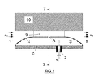
- Figures 1 and 2 show the scheme of a prototype in which the impulsion liquid, at P O pressure, is introduced in the conduit through the liquid inlet (1) and the gas to be dispersed, at P G pressure, is introduced through the gas supply conduit (2) into a pressure chamber (3).
- Said pressure chamber is limited by the conduit (2), an elastic membrane or diaphragm (4) and a rigid wall (5) to which the diaphragm is joined to avoid gas leaks.
- gas supply pressures from 5 mbar to 2 bar above the pressure P S of the discharge point (6) have been used.
- the gas supply pressure should be always slightly higher than that of the liquid in the injection section (7), where the cuts (8) made in the membrane are located, depending on the head loss of the gas injection system, to assure a certain ratio between liquid/gas flow rates.
Landscapes
- Chemical & Material Sciences (AREA)
- Chemical Kinetics & Catalysis (AREA)
Applications Claiming Priority (2)
| Application Number | Priority Date | Filing Date | Title |
|---|---|---|---|
| ES201200785A ES2445398B1 (es) | 2012-07-31 | 2012-07-31 | Dispositivo generador de burbujas de flujo cruzado y método de generación |
| PCT/ES2013/000183 WO2014023861A2 (es) | 2012-07-31 | 2013-07-29 | Dispositivo generador de burbujas de flujo cruzado y método de generación |
Publications (2)
| Publication Number | Publication Date |
|---|---|
| EP2881166A2 true EP2881166A2 (de) | 2015-06-10 |
| EP2881166A4 EP2881166A4 (de) | 2015-10-14 |
Family
ID=50068636
Family Applications (1)
| Application Number | Title | Priority Date | Filing Date |
|---|---|---|---|
| EP13827078.0A Withdrawn EP2881166A4 (de) | 2012-07-31 | 2013-07-29 | Blasenerzeugende querflussvorrichtung und blasenerzeugungsverfahren |
Country Status (8)
| Country | Link |
|---|---|
| US (1) | US20150298072A1 (de) |
| EP (1) | EP2881166A4 (de) |
| JP (1) | JP2015529554A (de) |
| CA (1) | CA2880679A1 (de) |
| CL (1) | CL2015000241A1 (de) |
| ES (1) | ES2445398B1 (de) |
| PE (1) | PE20150554A1 (de) |
| WO (1) | WO2014023861A2 (de) |
Family Cites Families (15)
| Publication number | Priority date | Publication date | Assignee | Title |
|---|---|---|---|---|
| US3545731A (en) | 1966-11-08 | 1970-12-08 | Gen Dynamics Corp | Apparatus for producing bubbles of very small,microscopic size |
| US3489396A (en) | 1968-03-14 | 1970-01-13 | Paul D Aragon | Stream water aerator |
| BE782431A (en) * | 1972-04-20 | 1972-08-16 | Centre Rech Metallurgique | Fuel and water emulsions for furnaces - formed by fuel and water vapour passed through porous elements |
| SE442173B (sv) | 1983-10-27 | 1985-12-09 | Sunds Defibrator | Anordning vid flotation av fibersuspensioner |
| DE4104287A1 (de) * | 1991-02-13 | 1992-08-20 | Schumacher Umwelt Trenntech | Langplattenbeluefter |
| DE4211648A1 (de) | 1992-04-07 | 1993-10-14 | Norbert Schneider | Plattenbelüfter |
| US5254260A (en) * | 1992-05-12 | 1993-10-19 | Union Carbide Chemicals & Plastics Technology Corporation | Membrane injector |
| CH685627A5 (de) * | 1992-08-31 | 1995-08-31 | Bontec Ag | Gasverteiler zum feinblasigen Belüften von Wasser. |
| AUPR907901A0 (en) * | 2001-11-23 | 2001-12-20 | Lawson, Thomas Urie | Device for aerating liquids |
| US8002249B2 (en) | 2002-08-13 | 2011-08-23 | Itt Manufacturing Enterprises, Inc. | Strip diffuser |
| AU2002953111A0 (en) * | 2002-12-05 | 2002-12-19 | U. S. Filter Wastewater Group, Inc. | Mixing chamber |
| DE602004009681T2 (de) * | 2003-05-16 | 2008-08-14 | Velocys, Inc., Plain City | Verfahren zur erzeugung einer emulsion durch verwendung einer mikrokanalverfahrentechnologie |
| ES2298020B1 (es) * | 2006-02-22 | 2009-07-23 | Universidad De Sevilla | Procedimiento y dispositivo de elevado rendimiento para la generacion de gotas y burbujas. |
| AU2007253670B2 (en) * | 2006-05-18 | 2012-01-19 | Marilyn Rayner | Manufacturing method of a membrane and a membrane thereof, for emulsification |
| US8002248B2 (en) | 2008-06-19 | 2011-08-23 | Kang Na Hsiung Enterprise Co., Ltd. | Diffuser for an aeration system |
-
2012
- 2012-07-31 ES ES201200785A patent/ES2445398B1/es active Active
-
2013
- 2013-07-29 US US14/418,539 patent/US20150298072A1/en not_active Abandoned
- 2013-07-29 JP JP2015524815A patent/JP2015529554A/ja active Pending
- 2013-07-29 CA CA2880679A patent/CA2880679A1/en active Pending
- 2013-07-29 PE PE2015000125A patent/PE20150554A1/es not_active Application Discontinuation
- 2013-07-29 WO PCT/ES2013/000183 patent/WO2014023861A2/es not_active Ceased
- 2013-07-29 EP EP13827078.0A patent/EP2881166A4/de not_active Withdrawn
-
2015
- 2015-01-30 CL CL2015000241A patent/CL2015000241A1/es unknown
Also Published As
| Publication number | Publication date |
|---|---|
| WO2014023861A3 (es) | 2014-04-03 |
| US20150298072A1 (en) | 2015-10-22 |
| WO2014023861A2 (es) | 2014-02-13 |
| CL2015000241A1 (es) | 2015-08-21 |
| CA2880679A1 (en) | 2014-02-13 |
| EP2881166A4 (de) | 2015-10-14 |
| ES2445398A2 (es) | 2014-03-03 |
| ES2445398R2 (es) | 2014-04-14 |
| ES2445398B1 (es) | 2015-01-29 |
| WO2014023861A4 (es) | 2014-06-05 |
| PE20150554A1 (es) | 2015-05-06 |
| JP2015529554A (ja) | 2015-10-08 |
Similar Documents
| Publication | Publication Date | Title |
|---|---|---|
| US20090309244A1 (en) | Procedure and device of high efficiency for the generation of drops and bubbles | |
| EP2411134B1 (de) | Tropfenerzeugung | |
| EP3103547B1 (de) | Vorrichtung zur erzeugung von feinblasiger flüssigkeit | |
| US10065167B2 (en) | Rotor and channel element apparatus with local constrictions for conducting sonochemical reactions with cavitation and methods for using the same | |
| KR101865240B1 (ko) | 나노 기포 발생장치 | |
| US20170028375A1 (en) | Device for conducting sonochemical reactions and processing liquids | |
| RU2186614C2 (ru) | Аппарат и способ осуществления взаимодействия фаз в системах газ-жидкость и жидкость-жидкость | |
| Ghahfarokhi et al. | Experimental and numerical assessment and performance optimization of a novel T-arrow microfluidic device to mix two fluids with different thermophysical properties | |
| KR20180130070A (ko) | 나노 기포 발생기 | |
| EP2881166A2 (de) | Blasenerzeugende querflussvorrichtung und blasenerzeugungsverfahren | |
| JPS6148970B2 (de) | ||
| Cheung et al. | Characterization of acoustic droplet formation in a microfluidic flow-focusing device | |
| CN120169199A (zh) | 含有自激振荡湍动剪切装置的曝气发生系统及其应用方法 | |
| US12251669B2 (en) | Shear flow nanobubble generator | |
| WO2012081072A1 (ja) | マイクロミキサー、およびマイクロ流体チップ | |
| CN120169196A (zh) | 碳化器和气泡水装置 | |
| CN116656473A (zh) | 一种高速相流生物细胞破碎装置 | |
| CN120589916B (zh) | 脉冲周期性振荡微孔气泡增效曝气系统及其应用方法 | |
| CN210145856U (zh) | 一种高浓度纳米级气泡发生装置 | |
| CN115228516B (zh) | 用于调控多相体系中分散相尺寸分布的限域单元和方法 | |
| RU2237511C2 (ru) | Статический смеситель | |
| CN121695724A (zh) | 旋流微气泡振荡发生器、系统及方法 | |
| Reichmann et al. | Internal jet formation during bubble generation in microchannels | |
| CN120325110A (zh) | 一种气体自吸入式微纳气泡生成装置 | |
| WO2024228638A1 (ru) | Устройство для создания газожидкостного потока |
Legal Events
| Date | Code | Title | Description |
|---|---|---|---|
| PUAI | Public reference made under article 153(3) epc to a published international application that has entered the european phase |
Free format text: ORIGINAL CODE: 0009012 |
|
| 17P | Request for examination filed |
Effective date: 20150210 |
|
| AK | Designated contracting states |
Kind code of ref document: A2 Designated state(s): AL AT BE BG CH CY CZ DE DK EE ES FI FR GB GR HR HU IE IS IT LI LT LU LV MC MK MT NL NO PL PT RO RS SE SI SK SM TR |
|
| AX | Request for extension of the european patent |
Extension state: BA ME |
|
| A4 | Supplementary search report drawn up and despatched |
Effective date: 20150915 |
|
| RIC1 | Information provided on ipc code assigned before grant |
Ipc: B01F 3/08 20060101ALI20150909BHEP Ipc: B01F 3/04 20060101AFI20150909BHEP |
|
| DAX | Request for extension of the european patent (deleted) | ||
| 17Q | First examination report despatched |
Effective date: 20170607 |
|
| STAA | Information on the status of an ep patent application or granted ep patent |
Free format text: STATUS: THE APPLICATION IS DEEMED TO BE WITHDRAWN |
|
| 18D | Application deemed to be withdrawn |
Effective date: 20171219 |