EP2881166A2 - Cross flow bubble generating device and generating method - Google Patents
Cross flow bubble generating device and generating method Download PDFInfo
- Publication number
- EP2881166A2 EP2881166A2 EP13827078.0A EP13827078A EP2881166A2 EP 2881166 A2 EP2881166 A2 EP 2881166A2 EP 13827078 A EP13827078 A EP 13827078A EP 2881166 A2 EP2881166 A2 EP 2881166A2
- Authority
- EP
- European Patent Office
- Prior art keywords
- pressure
- liquid
- dispersed
- fluid
- flow
- Prior art date
- Legal status (The legal status is an assumption and is not a legal conclusion. Google has not performed a legal analysis and makes no representation as to the accuracy of the status listed.)
- Withdrawn
Links
Images

Classifications
-
- B—PERFORMING OPERATIONS; TRANSPORTING
- B01—PHYSICAL OR CHEMICAL PROCESSES OR APPARATUS IN GENERAL
- B01F—MIXING, e.g. DISSOLVING, EMULSIFYING OR DISPERSING
- B01F23/00—Mixing according to the phases to be mixed, e.g. dispersing or emulsifying
- B01F23/20—Mixing gases with liquids
- B01F23/23—Mixing gases with liquids by introducing gases into liquid media, e.g. for producing aerated liquids
- B01F23/231—Mixing gases with liquids by introducing gases into liquid media, e.g. for producing aerated liquids by bubbling
- B01F23/23105—Arrangement or manipulation of the gas bubbling devices
- B01F23/2312—Diffusers
- B01F23/23124—Diffusers consisting of flexible porous or perforated material, e.g. fabric
- B01F23/231241—Diffusers consisting of flexible porous or perforated material, e.g. fabric the outlets being in the form of perforations
- B01F23/231242—Diffusers consisting of flexible porous or perforated material, e.g. fabric the outlets being in the form of perforations in the form of slits or cut-out openings
-
- B—PERFORMING OPERATIONS; TRANSPORTING
- B01—PHYSICAL OR CHEMICAL PROCESSES OR APPARATUS IN GENERAL
- B01F—MIXING, e.g. DISSOLVING, EMULSIFYING OR DISPERSING
- B01F23/00—Mixing according to the phases to be mixed, e.g. dispersing or emulsifying
- B01F23/20—Mixing gases with liquids
- B01F23/23—Mixing gases with liquids by introducing gases into liquid media, e.g. for producing aerated liquids
- B01F23/232—Mixing gases with liquids by introducing gases into liquid media, e.g. for producing aerated liquids using flow-mixing means for introducing the gases, e.g. baffles
- B01F23/2323—Mixing gases with liquids by introducing gases into liquid media, e.g. for producing aerated liquids using flow-mixing means for introducing the gases, e.g. baffles by circulating the flow in guiding constructions or conduits
-
- B—PERFORMING OPERATIONS; TRANSPORTING
- B01—PHYSICAL OR CHEMICAL PROCESSES OR APPARATUS IN GENERAL
- B01F—MIXING, e.g. DISSOLVING, EMULSIFYING OR DISPERSING
- B01F23/00—Mixing according to the phases to be mixed, e.g. dispersing or emulsifying
- B01F23/20—Mixing gases with liquids
- B01F23/23—Mixing gases with liquids by introducing gases into liquid media, e.g. for producing aerated liquids
- B01F23/231—Mixing gases with liquids by introducing gases into liquid media, e.g. for producing aerated liquids by bubbling
- B01F23/23105—Arrangement or manipulation of the gas bubbling devices
- B01F23/2312—Diffusers
- B01F23/23123—Diffusers consisting of rigid porous or perforated material
-
- B—PERFORMING OPERATIONS; TRANSPORTING
- B01—PHYSICAL OR CHEMICAL PROCESSES OR APPARATUS IN GENERAL
- B01F—MIXING, e.g. DISSOLVING, EMULSIFYING OR DISPERSING
- B01F25/00—Flow mixers; Mixers for falling materials, e.g. solid particles
- B01F25/30—Injector mixers
- B01F25/31—Injector mixers in conduits or tubes through which the main component flows
- B01F25/314—Injector mixers in conduits or tubes through which the main component flows wherein additional components are introduced at the circumference of the conduit
- B01F25/3142—Injector mixers in conduits or tubes through which the main component flows wherein additional components are introduced at the circumference of the conduit the conduit having a plurality of openings in the axial direction or in the circumferential direction
- B01F25/31421—Injector mixers in conduits or tubes through which the main component flows wherein additional components are introduced at the circumference of the conduit the conduit having a plurality of openings in the axial direction or in the circumferential direction the conduit being porous
-
- B—PERFORMING OPERATIONS; TRANSPORTING
- B01—PHYSICAL OR CHEMICAL PROCESSES OR APPARATUS IN GENERAL
- B01F—MIXING, e.g. DISSOLVING, EMULSIFYING OR DISPERSING
- B01F35/00—Accessories for mixers; Auxiliary operations or auxiliary devices; Parts or details of general application
- B01F35/71—Feed mechanisms
- B01F35/717—Feed mechanisms characterised by the means for feeding the components to the mixer
- B01F35/71805—Feed mechanisms characterised by the means for feeding the components to the mixer using valves, gates, orifices or openings
-
- B—PERFORMING OPERATIONS; TRANSPORTING
- B01—PHYSICAL OR CHEMICAL PROCESSES OR APPARATUS IN GENERAL
- B01F—MIXING, e.g. DISSOLVING, EMULSIFYING OR DISPERSING
- B01F2215/00—Auxiliary or complementary information in relation with mixing
- B01F2215/04—Technical information in relation with mixing
- B01F2215/0413—Numerical information
- B01F2215/0418—Geometrical information
- B01F2215/0431—Numerical size values, e.g. diameter of a hole or conduit, area, volume, length, width, or ratios thereof
Definitions
- the object of the present invention is a device allowing for the generation of bubbles in any type of liquid, with typical sizes ranging from several millimeters to less than 100 microns.
- the gas to be dispersed is introduced through small orifices or cutouts made in an elastic membrane and poured into a transversal liquid current (cross-flow).
- the fraction of energy used in the process to increase the surface of the liquid-gas interface must be maximized in relation with the energy transferred to the system.
- the device object of this invention is applicable to fields where an efficient generation of small bubbles is an important part of the process, such as the oxygenation and aeration of liquids, liquid-gas transfer processes, separation processes, etc.
- the main object in most of these applications is maximizing the contact area between the phases.
- the most interesting mode is the one called bubbling mode, which takes place with low gas flow rates and which shows a regular production of approximately spherical bubbles of uniform size near the injection orifice.
- the main drawback of this operation mode is that, for the usual geometrical configurations, the ratio between the injected gas flow rate and the impeller liquid flow rate is very low.
- the jet-mode When the gas flow rate is high, a continuous jet, anchored to the orifice outlet, is formed. This jet is later broken into irregular fragments in a chaotic way. This is known as the jet-mode.
- the average equivalent diameter of the bubbles generated at the outlet of the orifices in the bubbling mode is approximately: d eq ⁇ C ⁇ Q g / u l a , where Q g is the gas flow rate injected through the orifice and u l the speed of the liquid surrounding the jet.
- C and a are two experimental coefficients. Values of exponent a reported in the bibliography are between 1/3 and 1/2. ( P.F. Wace, M.S. Morrell y J. Woodrow 1987, Chemical Engineering Communications 62, pag. 93-106 ).
- the bubble diameter does not depend on the passage area of the liquid flow; for this reason, to minimize the consumption of the liquid impulsion and then increase the efficiency of these devices, the transversal area of the main conduit in the injection section should be as small as possible.
- the technical problem solved with the present invention is to enable the formation of small drops and bubbles by the generation of zones of intense shear in the flow.
- the present invention has as its essential advantage that small bubbles are formed directly from the anchored meniscus, instead of from jets or bubbles generated with any other procedure; this is a key aspect for maximizing the energy efficiency.
- the invention is advantageous in that the liquid flow driven over the orifices reduces substantially the size of the bubbles.
- the moving membrane or diaphragm avoids obstruction caused by small particles.
- the object of the present invention is a device for drop and bubble generation inside a liquid flow.
- this invention uses the injection through orifices in a transversal flow resulting in the formation of drops or bubbles that are typically within the millimeter or micrometer range.
- the proposed procedure is similar to those based on the Venturi effect in which, additionally, part of the kinetic energy provided to the flow through a divergent nozzle located adjacent to the injection zone is recovered.
- the cross-flow device disclosed herein advantageously shows a much lower energy consumption due to fact that the liquid flow in the main stream is minimized, and the bubbles detached from the orifices are substantially smaller.
- the injection through a diaphragm avoids the accumulation of solid particles inside the device, thus allowing for working with dirty fluids and high flow rates.
- SAE standard aeration efficiency
- the device for drop or bubble generation in a liquid comprises a first conduit for the admission of liquids, through which the impulsion liquid is supplied at pressure P o , and a second gas supply conduit through which the gas to be dispersed is supplied at pressure P G into a pressure chamber, and where between the first liquid supply conduit and the pressure chamber a diaphragm is placed, said diaphragm having injection orifices interconnecting the fluid to be dispersed with the liquid flowing through the first conduit, characterized by comprising a passage section between injection orifices, this is, the sectiob in the plane of the injection orifices, where the area of the transversal section in said injection zone is smaller than the result of multiplying 25 mm 2 by the number of injection orifices; all this in such a way that the coalescence between bubbles is avoided.
- there are flow separation means consisting of rigid elongate elements in the longitudinal sense of liquid flux in such a way that the liquid flows along parallel longitudinal channels against whose rigid elongate elements the diaphragm abuts, starting from a value corresponding to the pressure difference between the pressure at the entrance of the fluid to be dispersed and the discharge pressure of the device P G -P S .
- the range of the area in the transversal section in the injection zone of at least one part of the longitudinal parallel channels where the flow separates is between 0,001 mm 2 and 5 mm 2 , which are in practice the most useful values because mecanization is possible, and at the same time they are not so small as to have clogging problems in the flow circulation.
- the elongate rigid elements on which the diaphragm rests, which separates the first liquid supply conduit and the pressure chamber containing the flow to be dispersed, are attached to a wall of the first conduit for liquid admission, this wall being located opposite to the diaphragm.
- said flow separation means are a number of a plurality of grooves carried out in the diaphragm in the longitudinal (streamwise) direction of the liquid flow, where those grooves divide the liquid flow in several parallel conduits, starting from a value corresponding to the difference between the pressure at the entrance of the fluid to be dispersed and the discharge pressure of the device P G -P S .
- the geometry in the injection zone is defined by the angle formed between the straight line joining the centers of each pair of injection orifices and the trajectory of the bubbles that come out from any of those orifices; and where additionally said angle is greater than 10o.
- the method for the generation of cross-flow bubbles of the type implemented in the described device which comprises the stages of supplying an impulsion liquid at a pressure P O through a first liquid admission conduit and a second stage of introducing the gas to be dispersed at a pressure P G into a pressure chamber through a second gas supply conduit through a diaphragm having injection orifices interconnecting the fluid to be dispersed with the liquid flowing through the first conduit, characterized by comprising the injection through these injection orifices (8) across a transversal section with an area smaller than the result of multiplying 25 mm 2 by the number of injection orifices (8), avoiding coalescence between bubbles.
- the invention assumes the fact that the formation of a meniscus anchored at the outlet of an orifice is consequence of the balance between aerodynamic resistance forces, surface tension and inertia, since the effect of gravity is usually negligible in this process.
- the meniscus breaks up and small fragments in the form of drops or bubbles detach.
- a parametric range is used (set of special values related to the properties of the fluids, size of the orifices, flow rates, etc.) such that, fragments of a typical diameter of some hundreds microns are produced when the meniscus breaks up, so that the energy efficiency is maximum, in case that is the goal, being although other cases are possible in which the goal is to reach the minimum possible size at the expense of decreasing efficiency.
- P G P I + k g 2 ⁇ ⁇ g ⁇ u g 2 , where k g is the head loss constant of the orifice ( Idelchik, Handbook of Hydraulic Resistence, Hemisphere Pub. Corp., 1986 ), ⁇ g the gas density and u g the gas velocity at the orifice.
- SAE standard aeration efficiency in a kg of dissolved oxygen per kWh
- Q g is expressed in m 3 /h
- ⁇ g in kg/m 3 the power in kW
- ⁇ g is the fraction of O 2 dissolved in the liquid with respect to the injected oxygen
- Y O2 is the volumetric fraction of oxygen in the injected gas (0,21 for air in normal conditions).
- the value of ⁇ g depends only on the size and frequency of the generated bubbles. Therefore, to maximize the energy efficiency, the cost of impulsion has to be reduced without increasing too much the average size of the resulting bubbles, so that the value of ⁇ g is high.
- the size of the bubbles detached from the injection orifices depends on the liquid velocity but not on the liquid flow rate, it is convenient to maintain a high liquid velocity and reduce at the same time the liquid flow rate, which can be achieved reducing as much as possible the passage area of the conduit in the zone of injection of the fluid to be dispersed.
- the velocity at the dispersion zone should not be very high, as this would mean important kinetic energy losses downstream the device.
- the objective of the present device is to obtain smaller sizes in comparison with those achieved with the existing membrane diffusers, which produce bubbles with an average typical size of some millimeters.
- the injection is made through orifices that discharge in a transversal liquid flow (cross-flow); but to increase the efficiency even more, the transversal section in the injection zone has to be as small as possible. Any bubble with a diameter of less than 3 mm would have enough space in the main conduit if there was no interference between bubble trajectories and the area related to its injection orifice was 25 mm 2 . Therefore, in the device object of this invention, the passage area in the average transversal section in the injection zone is smaller than the result of multiplying 25 mm 2 by the number of injection orifices.
- the average passage section in the zone of injection depends on the gas supply pressure.
- solid elements elongated in the longitudinal (streamwise) direction of the flow, can be placed in order to divide the liquid conduit in several parallel conduits, such that the diaphragm abuts on the opposite wall starting from a value corresponding to the difference between the pressure at the inlet of the fluid to be dispersed and the discharge pressure of the device.
- These separators can be joined to the wall opposite to the diaphragm, be part of it, or even not be joined to any of the lateral walls of the liquid conduit.
- a practical embodiment of the invention is shown in the following figures, where the device requires the supply of a flow rate for the impulsion liquid and a flow rate for the gas or liquid to be dispersed. Both flow rates should be appropriate so that the system is within the parametric range of interest to reach the specifications of a concrete application.
- the number of orifices for the injection the dispersing fluid and the transversal section of the main conduit in the injection zone will be increased if the fluid velocity in this zone is very high for the required flow rates and therefore the efficiency is very low as a consequence of excessive pressure upstream the conduits.
- several parallel main conduits could be used to supply the impulsion liquid, such that in these conduits the gas or liquid to be dispersed is injected through multiple orifices.
- a larger flow rate of impulsion liquid and of gas or liquid to be dispersed can be supplied by any means in specific applications (oxygenation, gas-liquid or liquid-liquid chemical reactors, etc.) because this does not interfere with the operation of the device. Therefore, any method for supplying the impulsion liquid and the gas or liquid to be dispersed (compressors, volumetric pumps, compressed gas bottles, etc.) can be used.
- the flow rate of the fluid to be dispersed should be distributed as homogeneously as possible between the different orifices; this may require a minimum size for the injection orifices or any other method capable of homogeneously distributing the flow rate among the different supply points.
- the atomizer may be manufactured in multiple materials (metal, plastic, ceramic, glass), mainly depending on the specific application of the device.
- Figures 1 and 2 show the scheme of a prototype in which the impulsion liquid, at P O pressure, is introduced in the conduit through the liquid inlet (1) and the gas to be dispersed, at P G pressure, is introduced through the gas supply conduit (2) into a pressure chamber (3).
- Said pressure chamber is limited by the conduit (2), an elastic membrane or diaphragm (4) and a rigid wall (5) to which the diaphragm is joined to avoid gas leaks.
- gas supply pressures from 5 mbar to 2 bar above the pressure P S of the discharge point (6) have been used.
- the gas supply pressure should be always slightly higher than that of the liquid in the injection section (7), where the cuts (8) made in the membrane are located, depending on the head loss of the gas injection system, to assure a certain ratio between liquid/gas flow rates.
Landscapes
- Chemical & Material Sciences (AREA)
- Chemical Kinetics & Catalysis (AREA)
Abstract
Description
- The object of the present invention is a device allowing for the generation of bubbles in any type of liquid, with typical sizes ranging from several millimeters to less than 100 microns. For this purpose, the gas to be dispersed is introduced through small orifices or cutouts made in an elastic membrane and poured into a transversal liquid current (cross-flow). To make the drop or bubble generation as efficient as possible, the fraction of energy used in the process to increase the surface of the liquid-gas interface must be maximized in relation with the energy transferred to the system. The device object of this invention is applicable to fields where an efficient generation of small bubbles is an important part of the process, such as the oxygenation and aeration of liquids, liquid-gas transfer processes, separation processes, etc. The main object in most of these applications is maximizing the contact area between the phases.
- Existing oxygenation or aeration methods are based upon increasing the gas-liquid contact surface for bringing the concentration of dissolved oxygen closer to the saturation value. Most of the systems in use nowadays (C.E. Boyd 1998, Acuicultural Engineering 18, 9-40) try to fragment a mass of liquid in air, which is afterwards reintroduced into the mass of liquid, or else they produce bubbles which are directly introduced into the liquid. There are some devices producing the breakage of a gas or big bubble stream in the presence of a liquid flow; this is the case of venturis or some pumps which are air impellers or air suckers at the same time; however their yield is low. Its standard aeration efficiency (SAE) is hardly above two kilograms of oxygen per kilowatt-hour consumed.
- The most efficient way for bubble generation is the injection of gas inside a liquid co-flow. However, this means that for obtaining large flow rates the placement of hundreds or thousands of needles inside the stream would be required. It therefore seems more interesting to carry out the injection of the gas by means of several of orifices made in the wall of the main conduct, in such a way that at the outlet thereof the transversal liquid flow produces a strong drag over the gas coming out from the orifices. This cross-flow layout can generate diverse regimens or modes (S. E. Forrester y C.D. Rielly 1998, Chemical Engineering Science 53, pag. 1517-1527) according to the geometry of the device and the injected flow rates of gas and liquid. For gas-liquid transfer applications, the most interesting mode is the one called bubbling mode, which takes place with low gas flow rates and which shows a regular production of approximately spherical bubbles of uniform size near the injection orifice. The main drawback of this operation mode is that, for the usual geometrical configurations, the ratio between the injected gas flow rate and the impeller liquid flow rate is very low. When the gas flow rate is high, a continuous jet, anchored to the orifice outlet, is formed. This jet is later broken into irregular fragments in a chaotic way. This is known as the jet-mode.
- During the last decades, a large number of patents regarding bubble generation based on cross-flow procedures have been published (
US3489396 ,US4708829 andPCT/ES2007/000089 US2010133709 ,CN101397169 andDE4211648 ), in which air or oxygen injection is performed through small orifices made in a moving membrane (diaphragm) whose orifices close when there is a failure in the supply of gas. However, the size of the bubbles produced with these devices is significantly bigger than that of the bubbles produced in cross-flow instruments. Inventions related to cross-flow devices based on membranes have been previously published, such asUS patent 3,545,731 ; nevertheless, these are devices in which coalescence phenomena are very likely, the final result being the production of large bubbles. - The average equivalent diameter of the bubbles generated at the outlet of the orifices in the bubbling mode is approximately:

- The technical problem solved with the present invention is to enable the formation of small drops and bubbles by the generation of zones of intense shear in the flow. From a conceptual point of view, the present invention has as its essential advantage that small bubbles are formed directly from the anchored meniscus, instead of from jets or bubbles generated with any other procedure; this is a key aspect for maximizing the energy efficiency. In connection with the bubble generation systems through membranes or ceramic diffusers, the invention is advantageous in that the liquid flow driven over the orifices reduces substantially the size of the bubbles. With respect to other cross-flow devices, it is advantageous in that the moving membrane or diaphragm avoids obstruction caused by small particles.
- As stated above, the object of the present invention is a device for drop and bubble generation inside a liquid flow. Among the number of procedures commonly used for small drops and bubbles generation, this invention uses the injection through orifices in a transversal flow resulting in the formation of drops or bubbles that are typically within the millimeter or micrometer range.
- When a gas (or a miscible liquid) is injected in a transversal liquid flow, a meniscus appears that eventually detaches from the orifice. In this sense, the proposed procedure is similar to those based on the Venturi effect in which, additionally, part of the kinetic energy provided to the flow through a divergent nozzle located adjacent to the injection zone is recovered. However, the cross-flow device disclosed herein advantageously shows a much lower energy consumption due to fact that the liquid flow in the main stream is minimized, and the bubbles detached from the orifices are substantially smaller. On the other hand, the injection through a diaphragm avoids the accumulation of solid particles inside the device, thus allowing for working with dirty fluids and high flow rates.
- By means of this system, extremely small drops and bubbles can be produced, the only main limitations being the production costs of the devices. As an additional advantage, a strong agitation of the mixture takes place, the result being a substantial increase in the transfer between phases. The flow rate of the impulsion liquid and the fluid to be dispersed can be controlled through regulation valves.
- In the case of oxygenation or aeration of water, the standard aeration efficiency (SAE) may reach values above 10 kg of dissolved oxygen per kilowatt-hour. This may allow, among other applications, for an efficient dissolution of gases in liquids or, analogously, a significant increase of the reaction rate in liquid-gas or liquid-liquid chemical reactors.
- More specifically, in a first aspect of the invention, the device for drop or bubble generation in a liquid comprises a first conduit for the admission of liquids, through which the impulsion liquid is supplied at pressure Po , and a second gas supply conduit through which the gas to be dispersed is supplied at pressure PG into a pressure chamber, and where between the first liquid supply conduit and the pressure chamber a diaphragm is placed, said diaphragm having injection orifices interconnecting the fluid to be dispersed with the liquid flowing through the first conduit, characterized by comprising a passage section between injection orifices, this is, the sectiob in the plane of the injection orifices, where the area of the transversal section in said injection zone is smaller than the result of multiplying 25 mm2 by the number of injection orifices; all this in such a way that the coalescence between bubbles is avoided.
- In a particular embodiment, there are flow separation means consisting of rigid elongate elements in the longitudinal sense of liquid flux in such a way that the liquid flows along parallel longitudinal channels against whose rigid elongate elements the diaphragm abuts, starting from a value corresponding to the pressure difference between the pressure at the entrance of the fluid to be dispersed and the discharge pressure of the device PG-PS .
- In a particular embodiment, the range of the area in the transversal section in the injection zone of at least one part of the longitudinal parallel channels where the flow separates, is between 0,001 mm2 and 5 mm2, which are in practice the most useful values because mecanization is possible, and at the same time they are not so small as to have clogging problems in the flow circulation.
- The elongate rigid elements on which the diaphragm rests, which separates the first liquid supply conduit and the pressure chamber containing the flow to be dispersed, are attached to a wall of the first conduit for liquid admission, this wall being located opposite to the diaphragm.
- In a second particular embodiment, said flow separation means are a number of a plurality of grooves carried out in the diaphragm in the longitudinal (streamwise) direction of the liquid flow, where those grooves divide the liquid flow in several parallel conduits, starting from a value corresponding to the difference between the pressure at the entrance of the fluid to be dispersed and the discharge pressure of the device PG-PS .
- In a particular embodiment, the geometry in the injection zone is defined by the angle formed between the straight line joining the centers of each pair of injection orifices and the trajectory of the bubbles that come out from any of those orifices; and where additionally said angle is greater than 10º.
- In a second aspect of the invention, the method for the generation of cross-flow bubbles of the type implemented in the described device which comprises the stages of supplying an impulsion liquid at a pressure PO through a first liquid admission conduit and a second stage of introducing the gas to be dispersed at a pressure PG into a pressure chamber through a second gas supply conduit through a diaphragm having injection orifices interconnecting the fluid to be dispersed with the liquid flowing through the first conduit, characterized by comprising the injection through these injection orifices (8) across a transversal section with an area smaller than the result of multiplying 25 mm2 by the number of injection orifices (8), avoiding coalescence between bubbles.
- Along the description and claims, the word "comprises" and its variants do not pretend to exclude other technical characteristics, additives, components or steps. For those of skill in the art, other objects, advantages and characteristics of the invention will follow in part from the description and in part from the practice of the invention. The following examples and drawings are given for illustrative purposes and they should not be interpreted to limit the present invention. In addition, the present invention covers every possible combination of particular and preferred embodiments disclosed herein.
- Next, a number of drawings intended to provide for a better understanding of the invention and which are specifically related to a non-limiting exemplary embodiment of said invention are disclosed.
-
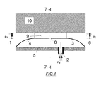
Fig. 1 .- Shows a section view of the bubble generator device which is the object of the invention, more specifically it corresponds to the average section of the device in the longitudinal (streamwise) direction of the flow. -
Fig. 2 .- Shows a second section view of the device ofFIG 1 which specifically corresponds to the transversal (spanwise) section of the flow in the zone where the orifices for the gas injection are located. - The reference characters used in the figures are the following:
- 1. Inlet for liquid admission.
- 2. Inlet for gas admission.
- 3. Pressure chamber for the gas to be dispersed in the liquid.
- 4. Elastic membrane (diaphragm).
- 5. Rigid wall to which the diaphragm is joined to avoid gas leak.
- 6. Outlet of the gas dispersed in the liquid.
- 7. Section where the orifices for gas injection are located. Said section corresponds to
figure 2 . - 8. Injection orifices in the membrane through which the gas is injected.
- 9. Rigid elongated elements in the longitudinal (streamwise) direction of the liquid flow that determine the position of the diaphragm.
- 10. Solid wall closing the liquid conduit.
- 11. Narrow channels dividing the liquid conduit.
- 12. Average section corresponding to the image of
figure 1 . - The invention assumes the fact that the formation of a meniscus anchored at the outlet of an orifice is consequence of the balance between aerodynamic resistance forces, surface tension and inertia, since the effect of gravity is usually negligible in this process. Depending on the geometric configuration and the velocity of the two fluids, the meniscus breaks up and small fragments in the form of drops or bubbles detach. A parametric range is used (set of special values related to the properties of the fluids, size of the orifices, flow rates, etc.) such that, fragments of a typical diameter of some hundreds microns are produced when the meniscus breaks up, so that the energy efficiency is maximum, in case that is the goal, being although other cases are possible in which the goal is to reach the minimum possible size at the expense of decreasing efficiency.
- In order to achieve a normal operation of the bubbles or drops generator, the flow of liquid and the flow of gas to be dispersed kept constant. The relationship between the supply pressure in the impulsion liquid, PO , and the pressure at the injection section, Pl , is


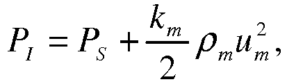
- In this process, energy consumption are related with the impulsion of both fluids (which is used for increasing the surface tension, the kinetic energy and in viscose dissipation) and therefore it can be calculated through the expression:

- For applications related to oxygenation or dissolution of gasses in liquids, the standard aeration efficiency (SAE) in a kg of dissolved oxygen per kWh can be obtained from:

- Since the size of the bubbles detached from the injection orifices depends on the liquid velocity but not on the liquid flow rate, it is convenient to maintain a high liquid velocity and reduce at the same time the liquid flow rate, which can be achieved reducing as much as possible the passage area of the conduit in the zone of injection of the fluid to be dispersed. The velocity at the dispersion zone should not be very high, as this would mean important kinetic energy losses downstream the device.
- The objective of the present device is to obtain smaller sizes in comparison with those achieved with the existing membrane diffusers, which produce bubbles with an average typical size of some millimeters. For this purpose, the injection is made through orifices that discharge in a transversal liquid flow (cross-flow); but to increase the efficiency even more, the transversal section in the injection zone has to be as small as possible. Any bubble with a diameter of less than 3 mm would have enough space in the main conduit if there was no interference between bubble trajectories and the area related to its injection orifice was 25 mm2. Therefore, in the device object of this invention, the passage area in the average transversal section in the injection zone is smaller than the result of multiplying 25 mm2 by the number of injection orifices. If the injection is made through a diaphragm, said passage section of liquid is reduced when the pressure inside the chamber containing the gas or liquid to be dispersed increases, this contributing to improve the efficiency of the device. The maximum value of the average transversal section that results from multiplying 25 mm2 by the number of orifices is measured when the pressure in the chamber containing the gas or liquid to be dispersed is stable or when the diaphragm rests on the opposite wall.
- To avoid coalescence phenomena between the drops or bubbles generated inside the device, it is essential that they do not interfere in their movement towards the outlet. The dispersion of the bubbles inside de device is very low; thus, if the angle formed by the straight line joining two orifices and the direction of the bubbles that coming out from those orifices is above 10 grades, the probability of coalescence is negligible.
- When the gas (or liquid to be dispersed) is injected through a diaphragm formed by an elastic membrane, the average passage section in the zone of injection depends on the gas supply pressure. To control the passage area in this injection zone, solid elements, elongated in the longitudinal (streamwise) direction of the flow, can be placed in order to divide the liquid conduit in several parallel conduits, such that the diaphragm abuts on the opposite wall starting from a value corresponding to the difference between the pressure at the inlet of the fluid to be dispersed and the discharge pressure of the device. These separators can be joined to the wall opposite to the diaphragm, be part of it, or even not be joined to any of the lateral walls of the liquid conduit.
- A practical embodiment of the invention is shown in the following figures, where the device requires the supply of a flow rate for the impulsion liquid and a flow rate for the gas or liquid to be dispersed. Both flow rates should be appropriate so that the system is within the parametric range of interest to reach the specifications of a concrete application. The number of orifices for the injection the dispersing fluid and the transversal section of the main conduit in the injection zone will be increased if the fluid velocity in this zone is very high for the required flow rates and therefore the efficiency is very low as a consequence of excessive pressure upstream the conduits. Moreover, several parallel main conduits could be used to supply the impulsion liquid, such that in these conduits the gas or liquid to be dispersed is injected through multiple orifices.
- A larger flow rate of impulsion liquid and of gas or liquid to be dispersed can be supplied by any means in specific applications (oxygenation, gas-liquid or liquid-liquid chemical reactors, etc.) because this does not interfere with the operation of the device. Therefore, any method for supplying the impulsion liquid and the gas or liquid to be dispersed (compressors, volumetric pumps, compressed gas bottles, etc.) can be used.
- The flow rate of the fluid to be dispersed should be distributed as homogeneously as possible between the different orifices; this may require a minimum size for the injection orifices or any other method capable of homogeneously distributing the flow rate among the different supply points. The atomizer may be manufactured in multiple materials (metal, plastic, ceramic, glass), mainly depending on the specific application of the device.
-
Figures 1 and2 show the scheme of a prototype in which the impulsion liquid, at PO pressure, is introduced in the conduit through the liquid inlet (1) and the gas to be dispersed, at PG pressure, is introduced through the gas supply conduit (2) into a pressure chamber (3). Said pressure chamber is limited by the conduit (2), an elastic membrane or diaphragm (4) and a rigid wall (5) to which the diaphragm is joined to avoid gas leaks. In this prototype, gas supply pressures from 5 mbar to 2 bar above the pressure PS of the discharge point (6) have been used. The gas supply pressure should be always slightly higher than that of the liquid in the injection section (7), where the cuts (8) made in the membrane are located, depending on the head loss of the gas injection system, to assure a certain ratio between liquid/gas flow rates. - As showed in
figure 2 , to assure a minimum passage section for the liquid in this prototype solid elements (9) joined to the upper wall (10) and elongated in the longitudinal (streamwise) direction of the liquid flow are provided, such that the water flows along narrow longitudinal channels (11). This figure also shows the position of section (12) which corresponds to the image offigure 1 . - The rest of dimensions in the prototype do not affect in any case to the generation of bubbles, provided that the pressure chamber is big enough compared with the injection orifices. It has not been accurately described how the liquid conduit is closed at the side ends, where the diaphragm has to be fixed against the opposite wall, because it is not relevant for the operation of the device. Similarly, it is neither relevant how the chamber of the fluid to be dispersed is closed.
PG = pressure inside the gas chamber.
PS = pressure at device exit.
Claims (9)
- Device for drops and bubbles generation in a liquid comprising a first conduit for the admission of liquids (1) through which the impulsion liquid is supplied at a pressure PO and a second supply conduit for the fluid to be dispersed in the form of drops or bubbles (2) thorough which the fluid to be dispersed is supplied at a pressure PG into a pressure chamber (3); and where between the first liquid supply conduit (1) and the pressure chamber (3), a diaphragm (4) is placed having injection orifices (8) allowing for the interconnection between the fluid to be dispersed and the liquid flowing along the first conduit (1), characterized by comprising a passage section between injection orifices (8), this is, the passing section at the injection zone, where the area of the transversal section in said injection zone is smaller than the result of multiplying 25 mm2 by the number of injection orifices (8); all this in such a way that the coalescence among bubbles is avoided.
- Device according to claim 1 where the geometry in the injection zone is defined by the angle formed by the straight line joining the centers of each pair of injection orifices (8) and the trajectory of the bubbles coming out from any of those orifices, said angle being greater than 10°.
- Device according to claim 1 comprising flow separation means along the longitudinal (streamwise) direction of the flow starting from a value corresponding to the difference between the pressure at the inlet of the fluid to be dispersed and the discharge pressure of the device PG -PS ; where the range of the area of the transversal section at the injection zone of at least one of the parallel longitudinal channels in which the fluid is divided is between 0,001 mm2 and 5 mm2.
- Device according to any of claims 1 and 3 comprising flow separation means along the longitudinal (streamwise) direction of the flow starting from a value corresponding to the difference between the pressure at the inlet of the fluid to be dispersed and the discharge pressure of the device PG -PS ; and where those means consist of elements (9) elongated in the longitudinal (streamwise) direction of the flow such that the liquid circulates along longitudinal parallel channels (11) against whose elongated rigid elements (9) the diaphragm (4) abuts starting from a value corresponding to the difference between the pressure at the entrance of the fluid to be dispersed and the discharge pressure in the device PG-PS .
- Device according to claim 4 where the elongated solid elements (9) on which the diaphragm (4) abuts, which also separates the first liquid supply conduit (1) and the pressure chamber (3) containing the fluid to be dispersed, are joined to a wall (10) of the first inlet conduit for liquids (1), this wall (10) being located opposite the diaphragm (4).
- Device according to any of claims 1 and 3 comprising flow separation means along the longitudinal (streamwise) direction of the flow starting from a value corresponding to the difference between the pressure at the inlet of the fluid to be dispersed and the discharge pressure of the device PG -PS ; and where those means consist of a number of grooves previously formed in the diaphragm (4) in the longitudinal (streamwise) direction of the liquid flow, where those grooves divide the liquid stream in several parallel conduits starting from a value corresponding to the difference between the pressure at the entrance of the fluid to be dispersed and the discharge pressure of the device PG-PS .
- Method for cross-flow generation of bubbles of the type implemented in the device of any of the claims 1 to 6 comprising the stage of supplying an impulsion liquid at a pressure PO through a first conduit for liquid admission (1) and a second stage of introducing the gas to be dispersed at a pressure PG in a pressure chamber (3) through a second gas supply conduit (2) through a diaphragm (4) having injection orifices (8) for interconnecting the fluid to be dispersed with the liquid flowing through the first conduit (1) characterized by comprising the injection through these injection orifices (8) across a transversal section with an area smaller than the result of multiplying 25 mm2 by the number of injection orifices (8), avoiding coalescence between bubbles.
- Method according to claim 7 comprising a flow separation stage along the longitudinal (streamwise) direction of the flow starting from the value corresponding to the difference in the pressure at the inlet of the fluid to be dispersed and the discharge pressure of the device PG -PS ; where the flow separation is made by elongated rigid elements (9) in the longitudinal (streamwise) direction of the fluid movement such that the liquid flows along parallel longitudinal channels (11) against whose elongated rigid elements (9) the diaphragm (4) abuts starting from a value corresponding to the difference between the pressure at the inlet of the fluid to be dispersed and the discharge pressure of the device PG-PS .
- Method according to claim 7 further comprising a flow separation along the longitudinal (streamwise) direction of the flow starting from a value corresponding to the difference in the pressure at the inlet of the fluid to be dispersed and the discharge pressure of the device PG-PS; and where the separation of the flow is made by a number of grooves made in the diaphragm (4) in the longitudinal (streamwise) direction of the liquids flow, where said grooves divide the liquid stream in several parallel conduits starting from a value corresponding to the difference between the pressure at the entrance of the fluid to be dispersed and the discharge pressure of the device PG-PS.
Applications Claiming Priority (2)
| Application Number | Priority Date | Filing Date | Title |
|---|---|---|---|
| ES201200785A ES2445398B1 (en) | 2012-07-31 | 2012-07-31 | Cross flow bubble generator device and generation method |
| PCT/ES2013/000183 WO2014023861A2 (en) | 2012-07-31 | 2013-07-29 | Cross flow bubble generating device and generating method |
Publications (2)
| Publication Number | Publication Date |
|---|---|
| EP2881166A2 true EP2881166A2 (en) | 2015-06-10 |
| EP2881166A4 EP2881166A4 (en) | 2015-10-14 |
Family
ID=50068636
Family Applications (1)
| Application Number | Title | Priority Date | Filing Date |
|---|---|---|---|
| EP13827078.0A Withdrawn EP2881166A4 (en) | 2012-07-31 | 2013-07-29 | CROSS-FLOW BUBBLE GENERATOR DEVICE AND GENERATION METHOD |
Country Status (8)
| Country | Link |
|---|---|
| US (1) | US20150298072A1 (en) |
| EP (1) | EP2881166A4 (en) |
| JP (1) | JP2015529554A (en) |
| CA (1) | CA2880679A1 (en) |
| CL (1) | CL2015000241A1 (en) |
| ES (1) | ES2445398B1 (en) |
| PE (1) | PE20150554A1 (en) |
| WO (1) | WO2014023861A2 (en) |
Family Cites Families (15)
| Publication number | Priority date | Publication date | Assignee | Title |
|---|---|---|---|---|
| US3545731A (en) | 1966-11-08 | 1970-12-08 | Gen Dynamics Corp | Apparatus for producing bubbles of very small,microscopic size |
| US3489396A (en) | 1968-03-14 | 1970-01-13 | Paul D Aragon | Stream water aerator |
| BE782431A (en) * | 1972-04-20 | 1972-08-16 | Centre Rech Metallurgique | Fuel and water emulsions for furnaces - formed by fuel and water vapour passed through porous elements |
| SE442173B (en) | 1983-10-27 | 1985-12-09 | Sunds Defibrator | DEVICE FOR FLOTATION OF FIBER SUSPENSIONS |
| DE4104287A1 (en) * | 1991-02-13 | 1992-08-20 | Schumacher Umwelt Trenntech | Long-plate liq. aerator - comprises vessel and aeration plate rounded at narrow ends, seal resting on shoulder near rim of vessel and surface of plate is not obstructed |
| DE4211648A1 (en) | 1992-04-07 | 1993-10-14 | Norbert Schneider | Flat-plate aerator esp. for waste water treatment tanks - aeration element is covered by tubular membrane clamped to end or head section of element, gas is introduced inside membrane via passage in head section |
| US5254260A (en) * | 1992-05-12 | 1993-10-19 | Union Carbide Chemicals & Plastics Technology Corporation | Membrane injector |
| CH685627A5 (en) * | 1992-08-31 | 1995-08-31 | Bontec Ag | Gas distributor for fine bubble aeration of water. |
| AUPR907901A0 (en) * | 2001-11-23 | 2001-12-20 | Lawson, Thomas Urie | Device for aerating liquids |
| US8002249B2 (en) | 2002-08-13 | 2011-08-23 | Itt Manufacturing Enterprises, Inc. | Strip diffuser |
| AU2002953111A0 (en) * | 2002-12-05 | 2002-12-19 | U. S. Filter Wastewater Group, Inc. | Mixing chamber |
| DE602004009681T2 (en) * | 2003-05-16 | 2008-08-14 | Velocys, Inc., Plain City | METHOD FOR GENERATING AN EMULSION THROUGH THE USE OF MICRO-CHANNEL PROCESS TECHNOLOGY |
| ES2298020B1 (en) * | 2006-02-22 | 2009-07-23 | Universidad De Sevilla | PROCEDURE AND DEVICE OF ELEVATED PERFORMANCE FOR THE GENERATION OF DROPS AND BUBBLES. |
| AU2007253670B2 (en) * | 2006-05-18 | 2012-01-19 | Marilyn Rayner | Manufacturing method of a membrane and a membrane thereof, for emulsification |
| US8002248B2 (en) | 2008-06-19 | 2011-08-23 | Kang Na Hsiung Enterprise Co., Ltd. | Diffuser for an aeration system |
-
2012
- 2012-07-31 ES ES201200785A patent/ES2445398B1/en active Active
-
2013
- 2013-07-29 US US14/418,539 patent/US20150298072A1/en not_active Abandoned
- 2013-07-29 JP JP2015524815A patent/JP2015529554A/en active Pending
- 2013-07-29 CA CA2880679A patent/CA2880679A1/en active Pending
- 2013-07-29 PE PE2015000125A patent/PE20150554A1/en not_active Application Discontinuation
- 2013-07-29 WO PCT/ES2013/000183 patent/WO2014023861A2/en not_active Ceased
- 2013-07-29 EP EP13827078.0A patent/EP2881166A4/en not_active Withdrawn
-
2015
- 2015-01-30 CL CL2015000241A patent/CL2015000241A1/en unknown
Also Published As
| Publication number | Publication date |
|---|---|
| WO2014023861A3 (en) | 2014-04-03 |
| US20150298072A1 (en) | 2015-10-22 |
| WO2014023861A2 (en) | 2014-02-13 |
| CL2015000241A1 (en) | 2015-08-21 |
| CA2880679A1 (en) | 2014-02-13 |
| EP2881166A4 (en) | 2015-10-14 |
| ES2445398A2 (en) | 2014-03-03 |
| ES2445398R2 (en) | 2014-04-14 |
| ES2445398B1 (en) | 2015-01-29 |
| WO2014023861A4 (en) | 2014-06-05 |
| PE20150554A1 (en) | 2015-05-06 |
| JP2015529554A (en) | 2015-10-08 |
Similar Documents
| Publication | Publication Date | Title |
|---|---|---|
| US20090309244A1 (en) | Procedure and device of high efficiency for the generation of drops and bubbles | |
| EP2411134B1 (en) | Droplet generation | |
| EP3103547B1 (en) | Device for generating fine bubble liquid | |
| US10065167B2 (en) | Rotor and channel element apparatus with local constrictions for conducting sonochemical reactions with cavitation and methods for using the same | |
| KR101865240B1 (en) | Device for generating bubble | |
| US20170028375A1 (en) | Device for conducting sonochemical reactions and processing liquids | |
| RU2186614C2 (en) | Apparatus and method of interaction of phases in gas- to-liquid and liquid-to-liquid systems | |
| Ghahfarokhi et al. | Experimental and numerical assessment and performance optimization of a novel T-arrow microfluidic device to mix two fluids with different thermophysical properties | |
| KR20180130070A (en) | Nano-Bubble Generator | |
| EP2881166A2 (en) | Cross flow bubble generating device and generating method | |
| JPS6148970B2 (en) | ||
| Cheung et al. | Characterization of acoustic droplet formation in a microfluidic flow-focusing device | |
| CN120169199A (en) | Aeration generating system containing self-excited oscillating turbulent shearing device and application method thereof | |
| US12251669B2 (en) | Shear flow nanobubble generator | |
| WO2012081072A1 (en) | Micromixer and microfluidic chip | |
| CN120169196A (en) | Carbonator and Sparkling Water Devices | |
| CN116656473A (en) | High-speed phase flow biological cell breaking device | |
| CN120589916B (en) | Pulse periodic oscillation micropore bubble synergistic aeration system and application method thereof | |
| CN210145856U (en) | High-concentration nanoscale bubble generating device | |
| CN115228516B (en) | Finite field unit and method for regulating and controlling size distribution of disperse phase in multiphase system | |
| RU2237511C2 (en) | Static mixer | |
| CN121695724A (en) | Swirl microbubble oscillation generator, system and method | |
| Reichmann et al. | Internal jet formation during bubble generation in microchannels | |
| CN120325110A (en) | A gas self-inhalation micro-nano bubble generating device | |
| WO2024228638A1 (en) | Device for creating a gas-liquid flow |
Legal Events
| Date | Code | Title | Description |
|---|---|---|---|
| PUAI | Public reference made under article 153(3) epc to a published international application that has entered the european phase |
Free format text: ORIGINAL CODE: 0009012 |
|
| 17P | Request for examination filed |
Effective date: 20150210 |
|
| AK | Designated contracting states |
Kind code of ref document: A2 Designated state(s): AL AT BE BG CH CY CZ DE DK EE ES FI FR GB GR HR HU IE IS IT LI LT LU LV MC MK MT NL NO PL PT RO RS SE SI SK SM TR |
|
| AX | Request for extension of the european patent |
Extension state: BA ME |
|
| A4 | Supplementary search report drawn up and despatched |
Effective date: 20150915 |
|
| RIC1 | Information provided on ipc code assigned before grant |
Ipc: B01F 3/08 20060101ALI20150909BHEP Ipc: B01F 3/04 20060101AFI20150909BHEP |
|
| DAX | Request for extension of the european patent (deleted) | ||
| 17Q | First examination report despatched |
Effective date: 20170607 |
|
| STAA | Information on the status of an ep patent application or granted ep patent |
Free format text: STATUS: THE APPLICATION IS DEEMED TO BE WITHDRAWN |
|
| 18D | Application deemed to be withdrawn |
Effective date: 20171219 |