EP2881160A1 - Procédé et dispositif de régénération de filtre de COV - Google Patents
Procédé et dispositif de régénération de filtre de COV Download PDFInfo
- Publication number
- EP2881160A1 EP2881160A1 EP13196146.8A EP13196146A EP2881160A1 EP 2881160 A1 EP2881160 A1 EP 2881160A1 EP 13196146 A EP13196146 A EP 13196146A EP 2881160 A1 EP2881160 A1 EP 2881160A1
- Authority
- EP
- European Patent Office
- Prior art keywords
- air
- filter
- voc
- voc filter
- tight space
- Prior art date
- Legal status (The legal status is an assumption and is not a legal conclusion. Google has not performed a legal analysis and makes no representation as to the accuracy of the status listed.)
- Ceased
Links
- 238000000034 method Methods 0.000 title claims abstract description 47
- 230000001172 regenerating effect Effects 0.000 title claims abstract description 18
- 239000012855 volatile organic compound Substances 0.000 claims abstract description 108
- 238000007254 oxidation reaction Methods 0.000 claims abstract description 34
- 230000003647 oxidation Effects 0.000 claims abstract description 33
- 230000001699 photocatalysis Effects 0.000 claims abstract description 27
- 239000011941 photocatalyst Substances 0.000 claims description 27
- 239000002250 absorbent Substances 0.000 claims description 26
- 230000002745 absorbent Effects 0.000 claims description 26
- 239000003054 catalyst Substances 0.000 claims description 10
- 230000001678 irradiating effect Effects 0.000 claims description 10
- 238000001914 filtration Methods 0.000 claims description 3
- 238000010438 heat treatment Methods 0.000 claims description 3
- WSFSSNUMVMOOMR-UHFFFAOYSA-N Formaldehyde Chemical compound O=C WSFSSNUMVMOOMR-UHFFFAOYSA-N 0.000 abstract description 21
- OKTJSMMVPCPJKN-UHFFFAOYSA-N Carbon Chemical compound [C] OKTJSMMVPCPJKN-UHFFFAOYSA-N 0.000 description 22
- 239000003344 environmental pollutant Substances 0.000 description 11
- 231100000719 pollutant Toxicity 0.000 description 11
- 238000011069 regeneration method Methods 0.000 description 10
- 230000008929 regeneration Effects 0.000 description 9
- XLYOFNOQVPJJNP-UHFFFAOYSA-N water Chemical compound O XLYOFNOQVPJJNP-UHFFFAOYSA-N 0.000 description 9
- CURLTUGMZLYLDI-UHFFFAOYSA-N Carbon dioxide Chemical compound O=C=O CURLTUGMZLYLDI-UHFFFAOYSA-N 0.000 description 8
- 239000001569 carbon dioxide Substances 0.000 description 7
- 229910002092 carbon dioxide Inorganic materials 0.000 description 7
- GWEVSGVZZGPLCZ-UHFFFAOYSA-N Titan oxide Chemical compound O=[Ti]=O GWEVSGVZZGPLCZ-UHFFFAOYSA-N 0.000 description 6
- 239000007789 gas Substances 0.000 description 6
- 230000008901 benefit Effects 0.000 description 4
- 238000011109 contamination Methods 0.000 description 4
- 239000000203 mixture Substances 0.000 description 4
- 239000000047 product Substances 0.000 description 4
- 239000006227 byproduct Substances 0.000 description 3
- 230000002195 synergetic effect Effects 0.000 description 3
- 238000010521 absorption reaction Methods 0.000 description 2
- 238000004887 air purification Methods 0.000 description 2
- QVGXLLKOCUKJST-UHFFFAOYSA-N atomic oxygen Chemical compound [O] QVGXLLKOCUKJST-UHFFFAOYSA-N 0.000 description 2
- 230000015572 biosynthetic process Effects 0.000 description 2
- 238000010586 diagram Methods 0.000 description 2
- 239000000463 material Substances 0.000 description 2
- 230000001590 oxidative effect Effects 0.000 description 2
- 229910052760 oxygen Inorganic materials 0.000 description 2
- 239000001301 oxygen Substances 0.000 description 2
- 229920006395 saturated elastomer Polymers 0.000 description 2
- 230000004913 activation Effects 0.000 description 1
- 239000000809 air pollutant Substances 0.000 description 1
- 231100001243 air pollutant Toxicity 0.000 description 1
- 230000008859 change Effects 0.000 description 1
- 238000006243 chemical reaction Methods 0.000 description 1
- 239000003638 chemical reducing agent Substances 0.000 description 1
- 239000000470 constituent Substances 0.000 description 1
- 239000000356 contaminant Substances 0.000 description 1
- 238000006731 degradation reaction Methods 0.000 description 1
- 230000001419 dependent effect Effects 0.000 description 1
- 238000003795 desorption Methods 0.000 description 1
- 239000010419 fine particle Substances 0.000 description 1
- TUJKJAMUKRIRHC-UHFFFAOYSA-N hydroxyl Chemical compound [OH] TUJKJAMUKRIRHC-UHFFFAOYSA-N 0.000 description 1
- 230000004048 modification Effects 0.000 description 1
- 238000012986 modification Methods 0.000 description 1
- 235000019645 odor Nutrition 0.000 description 1
- 230000009965 odorless effect Effects 0.000 description 1
- 150000002894 organic compounds Chemical class 0.000 description 1
- 239000007800 oxidant agent Substances 0.000 description 1
- 239000002245 particle Substances 0.000 description 1
- 239000002957 persistent organic pollutant Substances 0.000 description 1
- 238000011045 prefiltration Methods 0.000 description 1
- 230000008569 process Effects 0.000 description 1
- 238000006722 reduction reaction Methods 0.000 description 1
- 239000004065 semiconductor Substances 0.000 description 1
- 238000001179 sorption measurement Methods 0.000 description 1
- 238000001228 spectrum Methods 0.000 description 1
- 231100000331 toxic Toxicity 0.000 description 1
- 230000002588 toxic effect Effects 0.000 description 1
Images

Classifications
-
- B—PERFORMING OPERATIONS; TRANSPORTING
- B01—PHYSICAL OR CHEMICAL PROCESSES OR APPARATUS IN GENERAL
- B01D—SEPARATION
- B01D53/00—Separation of gases or vapours; Recovering vapours of volatile solvents from gases; Chemical or biological purification of waste gases, e.g. engine exhaust gases, smoke, fumes, flue gases, aerosols
- B01D53/02—Separation of gases or vapours; Recovering vapours of volatile solvents from gases; Chemical or biological purification of waste gases, e.g. engine exhaust gases, smoke, fumes, flue gases, aerosols by adsorption, e.g. preparative gas chromatography
- B01D53/04—Separation of gases or vapours; Recovering vapours of volatile solvents from gases; Chemical or biological purification of waste gases, e.g. engine exhaust gases, smoke, fumes, flue gases, aerosols by adsorption, e.g. preparative gas chromatography with stationary adsorbents
-
- B—PERFORMING OPERATIONS; TRANSPORTING
- B01—PHYSICAL OR CHEMICAL PROCESSES OR APPARATUS IN GENERAL
- B01D—SEPARATION
- B01D53/00—Separation of gases or vapours; Recovering vapours of volatile solvents from gases; Chemical or biological purification of waste gases, e.g. engine exhaust gases, smoke, fumes, flue gases, aerosols
- B01D53/34—Chemical or biological purification of waste gases
- B01D53/74—General processes for purification of waste gases; Apparatus or devices specially adapted therefor
- B01D53/86—Catalytic processes
- B01D53/8668—Removing organic compounds not provided for in B01D53/8603 - B01D53/8665
-
- B—PERFORMING OPERATIONS; TRANSPORTING
- B01—PHYSICAL OR CHEMICAL PROCESSES OR APPARATUS IN GENERAL
- B01D—SEPARATION
- B01D2257/00—Components to be removed
- B01D2257/70—Organic compounds not provided for in groups B01D2257/00 - B01D2257/602
- B01D2257/708—Volatile organic compounds V.O.C.'s
-
- B—PERFORMING OPERATIONS; TRANSPORTING
- B01—PHYSICAL OR CHEMICAL PROCESSES OR APPARATUS IN GENERAL
- B01D—SEPARATION
- B01D2259/00—Type of treatment
- B01D2259/80—Employing electric, magnetic, electromagnetic or wave energy, or particle radiation
- B01D2259/804—UV light
-
- B—PERFORMING OPERATIONS; TRANSPORTING
- B01—PHYSICAL OR CHEMICAL PROCESSES OR APPARATUS IN GENERAL
- B01D—SEPARATION
- B01D2259/00—Type of treatment
- B01D2259/80—Employing electric, magnetic, electromagnetic or wave energy, or particle radiation
- B01D2259/816—Sonic or ultrasonic vibration
-
- Y—GENERAL TAGGING OF NEW TECHNOLOGICAL DEVELOPMENTS; GENERAL TAGGING OF CROSS-SECTIONAL TECHNOLOGIES SPANNING OVER SEVERAL SECTIONS OF THE IPC; TECHNICAL SUBJECTS COVERED BY FORMER USPC CROSS-REFERENCE ART COLLECTIONS [XRACs] AND DIGESTS
- Y02—TECHNOLOGIES OR APPLICATIONS FOR MITIGATION OR ADAPTATION AGAINST CLIMATE CHANGE
- Y02A—TECHNOLOGIES FOR ADAPTATION TO CLIMATE CHANGE
- Y02A50/00—TECHNOLOGIES FOR ADAPTATION TO CLIMATE CHANGE in human health protection, e.g. against extreme weather
- Y02A50/20—Air quality improvement or preservation, e.g. vehicle emission control or emission reduction by using catalytic converters
Definitions
- the invention relates to a method and a device for regenerating an air purification filter, in particular, to a method and a device for regenerating a VOC (volatile organic compounds) filter.
- the invention further relates to an air purifier comprising the device for regenerating a VOC filter.
- ⁇ air purifiers Common methods of ensuring indoor air quality include controlling pollution sources, increasing the air exchange rate and using air purifiers.
- the use of air purifiers becomes more popular to eliminate indoor air pollutants.
- Traditional air purifiers use filters to remove particulate matters or sorption materials (e.g., granular activated carbon) to adsorb gases or odors.
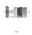
- the air purifier is composed of a series of filters, e.g. a pre-filter to remove large particles, a HEPA filter to remove fine particles, and an activated carbon filter to remove VOC and formaldehyde.
- Main filters integrated into an air purifier are illustrated in Fig. 1 . The polluted air passes through the filters in sequence, and the contaminants are removed and thus the clean air is generated.
- Activated carbon filter is currently the dominant filter on the market to remove gas pollutants.
- the advantage of activated carbon filter includes relatively cheap materials, no by-products, and good gas removal performance.
- activated carbon filter has very limited lifetime. For a 200 g activated carbon filter, the lifetime could be as short as two weeks. When the filter is saturated with VOC, continuing use of the filter could result in desorption of the pollutants back to the environment. Replacement of the filter is costly to consumer.
- one method is to modify the activated carbon with photocatalytic catalyst e.g. TiO 2 .
- the catalysts modified filter When the catalysts modified filter is saturated with pollutants, the filter can be regenerated by exposure to light for a required period. After the regeneration, filter regains the absorption capability and is able to remove the pollutants from the air again.
- PCO photocatalytic oxidation
- the positive holes (h + ) and electrons (e - ) are powerful oxidizing and reducing agents, respectively. They efficiently produce OH ⁇ (hydroxyl radical) and O 2 - through the following reactions: Oxidation reaction: h + + OH - ⁇ OR ⁇ ; Reduction reaction: e - + O 2ads ⁇ O - 2ads .
- OH ⁇ is a very powerful oxidizing species. It is derived from the oxidation of adsorbed water or adsorbed OH - . When OH ⁇ encounters organic pollutant, the degradation reaction takes place: OH ⁇ + VOC + O 2 ⁇ nCO 2 + mH 2 O.
- an embodiment of the invention provides a method for regenerating a VOC filter, the method comprising steps of: arranging the VOC filter in an air-tight space; and decomposing VOCs adsorbed by the VOC filter by photocatalytic oxidation.
- VOCs By decomposing VOCs in an air-tight space, the contamination of incomplete oxidation products is avoided. All the VOCs and formaldehyde absorbed onto the VOC removal filter will be completely decomposed to CO 2 and H 2 O before the atmosphere inside the air-tight space is released to the indoor environment.
- the decomposing step comprising: decomposing the VOCs adsorbed by the VOC filter in presence of photocatalyst provided in the air-tight space, the photocatalyst being independent of the VOC filter.
- the method further comprises a step of: releasing the VOCs adsorbed by the VOC filter into the air-tight space; the decomposing step comprises: decomposing the released VOCs by photocatalytic oxidation.
- the method further comprises vibrating the filter during the decomposing step.
- the vibrating step comprises: vibrating the filter with an ultrasonic source at a frequency higher than 16 kHz.
- the releasing step comprises: heating the VOC filter to release the absorbed VOCs.
- the method further comprises steps of: detecting concentration of VOCs within the air-tight space during the decomposing step; and stopping the decomposing step if the detected concentration is lower than a preset concentration threshold.
- the method further comprises a step of: obtaining property of a photocatalyst used in the photocatalytic oxidation; configuring a light source according to the obtained property of the catalyst.
- the air-tight space is provided with air.
- the method further comprising: providing reflector on/at the inner wall of the air-tight space, the reflector being able to reflect at least one of ultrasonic wave and light.
- an embodiment of the invention provides a device for regenerating a VOC filter, the device comprising: a container with an air-tight space for containing the VOC filter; a light source for irradiating absorbents of the VOC filter with light, and/or an ultrasonic source for irradiating absorbents of the VOC filter with ultrasonic, wherein the light and/or the ultrasonic enable(s) photocatalytic oxidation of photocatalyst provided on the absorbents; and a detector for detecting concentration of VOCs within the air-tight space.
- VOCs By decomposing VOCs in an air-tight space, the contamination of incomplete oxidation products is avoided. All the VOCs and formaldehyde absorbed onto the VOC removal filter will be completely decomposed to CO 2 and H 2 O before the atmosphere inside the air-tight space is released to the indoor environment. With such a configuration, a safe regeneration of the VOC filter can be achieved.
- photocatalyst is provided in the air-tight space, the photocatalyst being independent of the VOC filter.
- the device further comprises a vibrating unit for vibrating the absorbents of the VOC filter.
- the light is ultraviolet light.
- frequency of the ultrasonic is higher than 16 kHz.
- the air-tight space is provided with air.
- a reflector is provided on/at the inner wall of the air-tight space, the reflector being able to reflect at least one of ultrasonic wave and light.
- An air purifier comprising the device for regenerating a VOC filter according to any of the embodiments of the invention, wherein the container comprises an air tight door, the air tight door is used to form airflow channel during operation of air filtration.
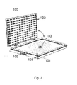
- Fig. 3 shows a schematic diagram of a device according to an embodiment of the invention.
- the device 100 comprises: a container 101 with an air-tight space for containing the VOC filter (not shown); a light source (an LED array) for irradiating absorbents of the VOC filter with light, and/or an ultrasonic source 103 for irradiating absorbents of the VOC filter with ultrasonic, wherein the light and/or the ultrasonic enable(s) photocatalytic oxidation of photocatalyst provided on the absorbents; and a detector 104 for detecting concentration of VOCs within the air-tight space.
- a light source an LED array
- an ultrasonic source 103 for irradiating absorbents of the VOC filter with ultrasonic, wherein the light and/or the ultrasonic enable(s) photocatalytic oxidation of photocatalyst provided on the absorbents
- a detector 104 for detecting concentration of VOCs within the air-tight space.
- an air tight regeneration device is used for the regeneration of air purification filter to avoid the contamination of incomplete oxidation products. All the VOCs and formaldehyde absorbed onto the VOC removal filter will be completely decomposed to CO 2 and H 2 O before the atmosphere inside the device is released to the indoor environment.
- a light source preferably an OLED type of light source is used to generate the light, which can avoid the restrain of natural sunlight.
- the VOC sensor is used to detect one/multiple chosen pollutant(s).
- the sensor monitors the regeneration progress by sensing the concentration change of pollutants.
- the VOC sensor also helps to ensure that all the VOCs and formaldehyde are completely decomposed to CO 2 and H 2 O before the atmosphere inside the device is released to the indoor environment, such that the secondary pollution is avoided.
- the ultrasonic source provides ultrasonic wave to the filter to create the vibration and assist photocatalytic oxidation.
- the ultrasonic improves the photocatalytic oxidation efficiency in two ways: on one hand, the mechanic waves vibrates the absorbents (such as granular activated carbon) and make all the absorbents receive the light; on the other hand, the ultrasonic is known to improve photocatalytic oxidation through synergistic effect, since to some extent, the ultrasonic phonon is strong enough for producing hydroxyl radicals. It should be noted that the mechanic waves also helps the releasing of the VOCs.
- photocatalyst is provided in the air-tight space, the photocatalyst being independent of the VOC filter.
- a meshed structure coated with photocatalyst can be provided in the air-tight space, thus photocatalytic oxidation is achieved by irradiating the meshed structure.
- the meshed structure can be arranged in vicinity of the light source/ ultrasonic source, so as to utilize the light/ultrasonic. With such a configuration, there is no need for integrating photocatalyst onto the absorbents of the filter.
- VOCs absorbed onto the VOC filter can be released by irradiating the absorbents of the filter or the meshed structure with light and/or ultrasonic, optionally, a heating unit can also be provided in the air-tight space for assisting the releasing of the VOCs.
- the device further comprises a vibrating unit 105 for vibrating the absorbents of the VOC filter.
- the ultrasonic source can be used for vibrating or rotating the absorbents (such as granular activated carbon), a vibrating unit (e.g. with an operation frequency of 20 to 1000 Hz) can also be utilized for this purpose.
- the light is ultraviolet light.
- Ultraviolet light has higher energy than visible light, positive holes (h + ) and electrons (e - ) can thus be produced with a higher efficiency.
- ultraviolet light can be used in concert with a variety of photocatalyst due to it's higher energy.
- frequency of the ultrasonic is higher than 16 kHz.
- the frequency of the ultrasonic can be chosen according to the power of the ultrasonic source and/or the mass of the absorbents.
- a frequency of the ultrasonic higher than 16 kHz ensures vibrating the absorbents and the synergistic effect.
- the air-tight space is provided with air.
- air refers to the mixture of gases that forms the Earth's atmosphere, which contains oxygen (O 2 ) and moisture (H 2 O) as well. As shown in Fig. 2 , these compositions can help the formation of O 2 - and OH ⁇ .
- a reflector is provided on/at the inner wall of the air-tight space, the reflector being able to reflect at least one of ultrasonic wave and light.
- the photocatalytic oxidation can take full advantage of the ultrasonic wave and/or the light.
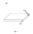
- Fig. 4 shows the outside structure of the device in Fig. 3 .
- the device has a flat shape, which matches the shape of a common VOC filter.
- a power button and a state indicator are provided at the outside of the device. After a VOC filter is put into the container and the device is closed, the power button can be pressed to switch on the device; when the state indicator changes from e.g. red to e.g. green, (which means the regeneration process is finished), the device can be switched off and reopened, and the VOC filter is ready for use.
- An embodiment of the invention provides a method for regenerating a VOC filter, the method comprising steps of: arranging the VOC filter in an air-tight space; and decomposing VOCs adsorbed by the VOC filter by photocatalytic oxidation.
- VOCs By decomposing VOCs in an air-tight space, the contamination of incomplete oxidation products is avoided. All the VOCs and formaldehyde absorbed onto the VOC removal filter will be completely decomposed to CO 2 and H 2 O before the atmosphere inside the air-tight space is released to the indoor environment.
- the decomposing step comprising: decomposing the VOCs adsorbed by the VOC filter in presence of photocatalyst provided in the air-tight space, the photocatalyst being independent of the VOC filter.
- a meshed structure coated with photocatalyst can be provided in the air-tight space, thus photocatalytic oxidation is achieved by irradiating the meshed structure.
- the meshed structure can be arranged in vicinity of the light source/ ultrasonic source, so as to utilize the light/ultrasonic. With such a configuration, there is no need for integrating photocatalyst onto the absorbents of the filter.
- the method further comprises a step of: releasing the VOCs adsorbed by the VOC filter into the air-tight space; the decomposing step comprises: decomposing the released VOCs by photocatalytic oxidation.
- Releasing the VOCs refers to escaping of VOCs by means of transferring energy (e.g. heat, light, electric and/or acoustic energy) to VOCs, which have already been absorbed onto the filter.
- the releasing step can be performed before the photocatalytic oxidation, and can also be performed during the photocatalytic oxidation.
- the combination of releasing step and decomposing step makes the photocatalytic oxidation more thorough, while the whole operation is time effective and free of operational difficulty.
- VOCs absorbed onto the VOC filter can be released by irradiating the absorbents of the filter or the meshed structure with light and/or ultrasonic, optionally, heat can also be applied to the VOC filter for assisting the releasing of the VOCs.
- the method further comprises vibrating the filter during the decomposing step.
- a mechanical wave e.g. with an operation frequency of 20 to 1000 Hz
- the absorbents such as granular activated carbon.
- Such mechanical wave is of high efficiency because the absorbents are generally granular.
- the vibrating step comprises: vibrating the filter with an ultrasonic source at a frequency higher than 16 kHz.
- the frequency of the ultrasonic can be chosen according to the power of the ultrasonic source and/or the mass of the absorbents.
- a frequency of the ultrasonic higher than 16 kHz ensures vibrating the absorbents and the synergistic effect.
- the method further comprises steps of: detecting concentration of VOCs within the air-tight space during the decomposing step; and stopping the decomposing step if the detected concentration is lower than a preset concentration threshold.
- the method further comprises a step of: obtaining property of a photocatalyst used in the photocatalytic oxidation; configuring a light source according to the obtained property of the catalyst.
- the property of the photocatalyst can be obtained by input of the user, or by simply reading the tag of the VOC filter.
- light and/or ultrasonic can be chosen for matching the photocatalyst.
- the specifics e.g. intensity and spectrum scope of the light source and/or the ultrasonic source depend on the catalysts coated on the absorbents. For instance, if the catalyst is TiO 2 , since the absorption range is below 388 nm, therefore a UV light source will be used. If the catalyst is visible light catalyst, then a visible light source is provided.
- the air-tight space is provided with air.
- air refers to the mixture of gases that forms the Earth's atmosphere, which contains oxygen (O 2 ) and moisture (H 2 O) as well. As shown in Fig. 2 , these compositions can help the formation of O 2 - and OH ⁇ .
- the method further comprising: providing reflector on/at the inner wall of the air-tight space, the reflector being able to reflect at least one of ultrasonic wave and light.
- An air purifier comprising the device for regenerating a VOC filter according to any of the embodiments of the invention, wherein the container comprises an air tight door, the air tight door is used to form airflow channel during operation of air filtration.
Landscapes
- Engineering & Computer Science (AREA)
- Chemical & Material Sciences (AREA)
- Environmental & Geological Engineering (AREA)
- Analytical Chemistry (AREA)
- General Chemical & Material Sciences (AREA)
- Oil, Petroleum & Natural Gas (AREA)
- Chemical Kinetics & Catalysis (AREA)
- Health & Medical Sciences (AREA)
- Biomedical Technology (AREA)
- Disinfection, Sterilisation Or Deodorisation Of Air (AREA)
Priority Applications (1)
| Application Number | Priority Date | Filing Date | Title |
|---|---|---|---|
| EP13196146.8A EP2881160A1 (fr) | 2013-12-09 | 2013-12-09 | Procédé et dispositif de régénération de filtre de COV |
Applications Claiming Priority (1)
| Application Number | Priority Date | Filing Date | Title |
|---|---|---|---|
| EP13196146.8A EP2881160A1 (fr) | 2013-12-09 | 2013-12-09 | Procédé et dispositif de régénération de filtre de COV |
Publications (1)
| Publication Number | Publication Date |
|---|---|
| EP2881160A1 true EP2881160A1 (fr) | 2015-06-10 |
Family
ID=49725060
Family Applications (1)
| Application Number | Title | Priority Date | Filing Date |
|---|---|---|---|
| EP13196146.8A Ceased EP2881160A1 (fr) | 2013-12-09 | 2013-12-09 | Procédé et dispositif de régénération de filtre de COV |
Country Status (1)
| Country | Link |
|---|---|
| EP (1) | EP2881160A1 (fr) |
Cited By (1)
| Publication number | Priority date | Publication date | Assignee | Title |
|---|---|---|---|---|
| CN111773900A (zh) * | 2020-07-07 | 2020-10-16 | 浙江工贸职业技术学院 | 应用于工业废气中可挥发有机化合物的在线检测净化装置 |
Citations (5)
| Publication number | Priority date | Publication date | Assignee | Title |
|---|---|---|---|---|
| US6358374B1 (en) * | 1999-12-17 | 2002-03-19 | Carrier Corporation | Integrated photocatalytic and adsorbent technologies for the removal of gaseous contaminants |
| US20050061656A1 (en) * | 2003-09-23 | 2005-03-24 | Benoit Jeffrey T. | Reflective lamp to maximize light delivery to a photoactive catalyst |
| US20110027130A1 (en) * | 2009-06-03 | 2011-02-03 | Willette Christopher C | Adsorptive photo-catalytic oxidation air purification device |
| WO2012082476A2 (fr) * | 2010-12-16 | 2012-06-21 | Advanced Technologies & Testing Laboratories, Inc. | Dispositif et procédé de désinfection de fluide |
| EP2581127A1 (fr) * | 2011-10-11 | 2013-04-17 | IBL Umwelt-und Biotechnik GmbH | Procédé de nettoyage à l'air, de préférence de liaisons organiques volatiles |
-
2013
- 2013-12-09 EP EP13196146.8A patent/EP2881160A1/fr not_active Ceased
Patent Citations (5)
| Publication number | Priority date | Publication date | Assignee | Title |
|---|---|---|---|---|
| US6358374B1 (en) * | 1999-12-17 | 2002-03-19 | Carrier Corporation | Integrated photocatalytic and adsorbent technologies for the removal of gaseous contaminants |
| US20050061656A1 (en) * | 2003-09-23 | 2005-03-24 | Benoit Jeffrey T. | Reflective lamp to maximize light delivery to a photoactive catalyst |
| US20110027130A1 (en) * | 2009-06-03 | 2011-02-03 | Willette Christopher C | Adsorptive photo-catalytic oxidation air purification device |
| WO2012082476A2 (fr) * | 2010-12-16 | 2012-06-21 | Advanced Technologies & Testing Laboratories, Inc. | Dispositif et procédé de désinfection de fluide |
| EP2581127A1 (fr) * | 2011-10-11 | 2013-04-17 | IBL Umwelt-und Biotechnik GmbH | Procédé de nettoyage à l'air, de préférence de liaisons organiques volatiles |
Cited By (1)
| Publication number | Priority date | Publication date | Assignee | Title |
|---|---|---|---|---|
| CN111773900A (zh) * | 2020-07-07 | 2020-10-16 | 浙江工贸职业技术学院 | 应用于工业废气中可挥发有机化合物的在线检测净化装置 |
Similar Documents
| Publication | Publication Date | Title |
|---|---|---|
| US11730849B2 (en) | Air treatment method | |
| US10933158B2 (en) | Air treatment system and method of use | |
| CN104848443B (zh) | 一种再生型空气净化系统 | |
| US20160045866A1 (en) | Device of deodorizing and minimizing voc in exhaust gas with photocatalyst | |
| CN201260930Y (zh) | 高效空气净化机 | |
| CN104906951A (zh) | 一种光生臭氧催化氧化去除挥发性有机物的方法及装置 | |
| CN103611418A (zh) | 有机废气的联合处理装置及处理方法 | |
| CN107044690A (zh) | 一种移动式空气净化设备 | |
| WO2019152996A1 (fr) | Système et méthode pour traitement de l'air | |
| CN109464692B (zh) | 高阶空气净化器用芯体 | |
| JP3180042U (ja) | 空気清浄化システム | |
| JP2002172157A (ja) | 空気清浄装置 | |
| JPH1147635A (ja) | 空気清浄化装置 | |
| EP2881160A1 (fr) | Procédé et dispositif de régénération de filtre de COV | |
| CN203010785U (zh) | 空气净化器 | |
| CN205939487U (zh) | 一种灯具上的空气净化装置 | |
| CN201500322U (zh) | 车载光触媒空气净化器 | |
| CN204477786U (zh) | 一种带空气净化的台灯 | |
| JP2002306587A (ja) | 空気浄化装置および空気浄化フィルタ | |
| JPH0360720A (ja) | 空気清浄機 | |
| CN204543809U (zh) | 专用空气净化器 | |
| CN103388859A (zh) | 全方位进风空气净化装置 | |
| CN102614777A (zh) | 一种污泥臭气光催化氧化处理系统及利用其处理污泥臭气的方法 | |
| CN209809931U (zh) | 一种智能型空气净化器 | |
| KR101144601B1 (ko) | 금속산화물촉매를 이용한 공기정화용 유닛 |
Legal Events
| Date | Code | Title | Description |
|---|---|---|---|
| PUAI | Public reference made under article 153(3) epc to a published international application that has entered the european phase |
Free format text: ORIGINAL CODE: 0009012 |
|
| 17P | Request for examination filed |
Effective date: 20131209 |
|
| AK | Designated contracting states |
Kind code of ref document: A1 Designated state(s): AL AT BE BG CH CY CZ DE DK EE ES FI FR GB GR HR HU IE IS IT LI LT LU LV MC MK MT NL NO PL PT RO RS SE SI SK SM TR |
|
| AX | Request for extension of the european patent |
Extension state: BA ME |
|
| STAA | Information on the status of an ep patent application or granted ep patent |
Free format text: STATUS: THE APPLICATION HAS BEEN REFUSED |
|
| 18R | Application refused |
Effective date: 20150627 |