EP2880975A1 - Spinning reel - Google Patents
Spinning reel Download PDFInfo
- Publication number
- EP2880975A1 EP2880975A1 EP14193782.1A EP14193782A EP2880975A1 EP 2880975 A1 EP2880975 A1 EP 2880975A1 EP 14193782 A EP14193782 A EP 14193782A EP 2880975 A1 EP2880975 A1 EP 2880975A1
- Authority
- EP
- European Patent Office
- Prior art keywords
- spool
- seal member
- flange
- spinning reel
- distal end
- Prior art date
- Legal status (The legal status is an assumption and is not a legal conclusion. Google has not performed a legal analysis and makes no representation as to the accuracy of the status listed.)
- Granted
Links
Images

Classifications
-
- A—HUMAN NECESSITIES
- A01—AGRICULTURE; FORESTRY; ANIMAL HUSBANDRY; HUNTING; TRAPPING; FISHING
- A01K—ANIMAL HUSBANDRY; AVICULTURE; APICULTURE; PISCICULTURE; FISHING; REARING OR BREEDING ANIMALS, NOT OTHERWISE PROVIDED FOR; NEW BREEDS OF ANIMALS
- A01K89/00—Reels
- A01K89/015—Reels with a rotary drum, i.e. with a rotating spool
-
- A—HUMAN NECESSITIES
- A01—AGRICULTURE; FORESTRY; ANIMAL HUSBANDRY; HUNTING; TRAPPING; FISHING
- A01K—ANIMAL HUSBANDRY; AVICULTURE; APICULTURE; PISCICULTURE; FISHING; REARING OR BREEDING ANIMALS, NOT OTHERWISE PROVIDED FOR; NEW BREEDS OF ANIMALS
- A01K89/00—Reels
- A01K89/01—Reels with pick-up, i.e. with the guiding member rotating and the spool not rotating during normal retrieval of the line
- A01K89/0111—Spool details
-
- A—HUMAN NECESSITIES
- A01—AGRICULTURE; FORESTRY; ANIMAL HUSBANDRY; HUNTING; TRAPPING; FISHING
- A01K—ANIMAL HUSBANDRY; AVICULTURE; APICULTURE; PISCICULTURE; FISHING; REARING OR BREEDING ANIMALS, NOT OTHERWISE PROVIDED FOR; NEW BREEDS OF ANIMALS
- A01K89/00—Reels
- A01K89/02—Brake devices for reels
-
- A—HUMAN NECESSITIES
- A01—AGRICULTURE; FORESTRY; ANIMAL HUSBANDRY; HUNTING; TRAPPING; FISHING
- A01K—ANIMAL HUSBANDRY; AVICULTURE; APICULTURE; PISCICULTURE; FISHING; REARING OR BREEDING ANIMALS, NOT OTHERWISE PROVIDED FOR; NEW BREEDS OF ANIMALS
- A01K89/00—Reels
- A01K89/02—Brake devices for reels
- A01K89/027—Brake devices for reels with pick-up, i.e. for reels with the guiding member rotating and the spool not rotating during normal retrieval of the line
- A01K89/028—Continuously applied
- A01K89/03—Continuously applied between spool and spool shaft
-
- A—HUMAN NECESSITIES
- A01—AGRICULTURE; FORESTRY; ANIMAL HUSBANDRY; HUNTING; TRAPPING; FISHING
- A01K—ANIMAL HUSBANDRY; AVICULTURE; APICULTURE; PISCICULTURE; FISHING; REARING OR BREEDING ANIMALS, NOT OTHERWISE PROVIDED FOR; NEW BREEDS OF ANIMALS
- A01K89/00—Reels
- A01K89/02—Brake devices for reels
- A01K89/033—Brake devices for reels with a rotary drum, i.e. for reels with a rotating spool
Definitions
- the present invention relates to a spinning reel that forwardly casting a fishing line.
- a conventional spinning reel comprises a reel body unit, a spool shaft, a spool, a drag mechanism, and a seal member.
- a spinning reel is for example disclosed in the Japanese Laid-Open Patent Publication No. 2002-204640 .
- the spool shaft is supported by the reel body unit so as to be movable in a longitudinal direction.
- the spool is attached to the spool shaft.
- the spool comprises a line winding cylinder part and a flange that is on the front side and the rear side of the line winding cylinder part.
- the drag mechanism brakes a rotation of the spool and is housed inside of the spool.
- the drag mechanism comprises a braking member that brakes the rotation of the spool and a drag adjuster that is attached to the distal end of the spool shaft and that adjusts the frictional coupling force of the braking member.
- the seal member is disposed inside of the line winding cylinder part of the spool between the drag adjuster and the braking member. Intrusion of foreign matter into the braking member of the drag mechanism from the front of the spinning reel is prevented by abutting the distal end portion of this seal member to the inner peripheral surface of the line winding cylinder part (more accurately, the inner peripheral surface of the flange fixing member).
- the distal end portion of the seal member abuts the inner peripheral surface of the line winding cylinder part of the spool in order to prevent the intrusion of foreign matter into the braking member of the drag mechanism from the front of the spinning reel.
- the entirety of the reel member from the proximal end portion to the distal end portion be disposed inside of the line winding cylinder part. That is, a space for disposing the entire seal member inside of the line winding cylinder part needs to be secured inside of the line winding cylinder part. For this reason, the outer diameter of the line winding cylinder part of the spool is large, so that it is possible that a sufficient amount of line winding could not be accomplished.
- the present invention is made in light of the above-described problems, and the object of the present invention is to provide a spinning reel that can sufficiently wind fishing line to a spool. Another object of the present invention is to provide a spinning reel that can reliably prevent the intrusion of foreign matter inside of the spool
- the spinning reel according to a first aspect is a spinning reel that forwardly casts a fishing line.
- the present spinning reel comprises a reel body unit, a spool shaft, a spool, a drag mechanism, and a seal member.
- the spool shaft has a distal end and is supported by the reel body unit to be movable in the longitudinal direction.
- the spool is attached to the spool shaft.
- the spool comprises a line winding cylinder part having a front side.
- a fishing line is wound to the outside of the line winding cylinder part.
- a front flange is disposed on the front side of the line winding cylinder part.
- the space that is formed between the front flange and the drag adjuster is closed with the seal member abutting the front flange. Accordingly, in the present spinning reel, the seal member abuts the front flange; therefore, it is not necessary to secure a space for disposing the entire seal member inside of the line winding cylinder part of the spool. Therefore, when compared to conventional technology, the outer diameter of the line winding cylinder part of the spool can be small, and sufficient fishing line can be wound around the spool. That is, it is possible to provide a spinning reel that can sufficiently wind fishing line to the spool.
- the spinning reel according to a second aspect comprises the spinning reel recited in the first aspect, with the front flange comprising a flange portion that extends in a direction away from the spool shaft and a connecting portion that connects the line winding cylinder part and the flange portion.
- the flange portion extends in a radial direction.
- At least one of the flange portion and the connecting portion comprises a projection. The distal end portion of the seal member can abut the projection.
- the spinning reel according to a third aspect comprises the spinning reel recited in the second aspect, with the projection protruding forward from at least one of the flange portion and the connecting portion.
- the distal end portion of the seal member can abut a projection that protrudes forward from at least one of the flange portion and the connecting portion, the intrusion of foreign matter along the flange portion and/or the connecting portion can be more reliably prevented.
- the spinning reel according to a fourth aspect comprises the spinning reel recited in the second aspect or in the third aspect, with the distal end portion of the projection being bent toward the spool shaft.
- the distal end portion of the seal member can be disposed between the part where the distal end portion of the projection is bent and at least one of the flange portion and the connecting portion, so that the distal end portion of the seal member can be covered by the projection. Accordingly, the distal end portion of the seal member can be protected, and the intrusion of foreign matter along the flange portion and/or the connecting portion can be more reliably prevented.
- the spinning reel according to a fifth aspect comprises the spinning reel recited in any one of the first to the fourth aspects, with a distal end side rear surface of the seal member abutting the front flange.
- the distal end side rear surface of the seal member can be in surface contact with the front flange. Accordingly, the seal member can reliably prevent the intrusion of foreign matter. That is, a spinning reel that can reliably prevent the intrusion of foreign matter inside of the spool can be provided.
- the distal end side rear surface of the seal member can be in surface contact with the abutting plane of the connecting portion. Accordingly, the seal member can reliably prevent the intrusion of foreign matter.
- the spinning reel according to a seventh aspect comprises the spinning reel recited in any one of the first to the sixth aspects, with the drag adjuster comprising an adjustment knob, an abutting member, and a fixing member.
- the adjustment knob is screwed to the distal end of the spool shaft.
- the abutting member is disposed on the adjustment knob and can abut a front surface of the seal member.
- the fixing member fixes the abutting member to the adjustment knob.
- the intrusion of foreign matter inside of the drag adjuster can be prevented by abutting the abutting member of the drag adjuster to the front surface of the seal member.
- the spinning reel according to a ninth aspect comprises the spinning reel recited in the eighth aspect, with the boss portion comprising a body section and a large-diameter section that is disposed on the outer periphery of the body section.
- the holding portion is held by the head portion and the large-diameter section.
- the holding portion of the abutting member is held by the head portion of the fixing member and the large-diameter section of the boss portion of the adjustment knob, so that the abutting member can be securely fixed to the adjustment knob by the fixing member.
- a spinning reel that can sufficiently wind fishing line to a spool is provided. Additionally, according to the present invention, a spinning reel that can reliably prevent the intrusion of foreign matter inside of the spool is provided.
- the handle 1 is rotatably mounted to the reel body unit 2.
- the handle 1 comprises a handle arm 38 that can be folded and a handle grip 39 that is rotatably mounted to the distal end of the handle arm 38.
- the handle 1 is attached to a master gear shaft 10, which is a rotating shaft.
- the reel body unit 2 comprises a longitudinal rod mounting portion 2c that is mounted to a fishing rod, a reel body 2a that is disposed to be spaced apart from the rod mounting portion 2c, and a leg portion 2b that couples the rod mounting portion 2c and the reel body 2a.
- the reel body 2a comprises a mechanism mounting space inside.
- the reel body 2a is integrally formed with the leg portion 2b, and the side is open. The opening of the reel body 2a is closed by a lid member (not shown).
- the rear portion of the reel body unit 2 is covered by a guard member 35.
- the rotor drive mechanism 5 is a mechanism for rotating the rotor 3 in conjunction with the handle 1.
- the rotor drive mechanism 5 comprises a master gear shaft 10 to which the handle 1 is fixed so as to be integrally rotatable therewith, a master gear 11 that rotates along with the master gear shaft 10, and a pinion gear 12 that meshes with the master gear 11.
- the master gear 11 rotates along with the master gear shaft 10.
- the master gear 11 is integrally formed with the master gear shaft 10. However, the master gear 11 can he separate from the master gear shaft 10.
- the pinion gear 12 is a member that meshes with the master gear 11.
- the pinion gear 12 is formed in a tubular shape.
- the front portion 12a of the pinion gear 12 extends to the spool 4 side through a through-hole 3e of the rotor 3.
- the front portion 12a of the pinion gear 12 is also fixed to the rotor 3 via a nut 13. That is, the rotor 3 is integrally and rotatably fixed to the pinion gear 12 by the nut 13 in the front portion 12a of the pinion gear 12.
- the lever brake mechanism 6 is a mechanism for braking the rotation of the rotor 3 in the line delivering direction (the reverse rotation). That is, the lever brake mechanism 6 is a rotor braking device. As shown in Figure 1 , the lever brake mechanism 6 comprises a rotor brake unit 16, as well as a brake lever 17 for adjusting the braking force of the rotor brake unit 16. The rotor brake unit 16 is disposed on the inner peripheral part of the rotor 3 and brakes the rotor 3. The brake lever 17 can switch the state of the rotor brake unit 16 between a prescribed braking state in which the rotor brake unit 16 brakes the rotor 3 and a brake release state in which the braking of the rotor brake unit 16 is released.
- the oscillating mechanism 20 operates in conjunction with the rotation of the handle 1 and reciprocally moves the spool 4 back and forth via the spool shaft 8.
- the oscillating mechanism 20 is a traverse cam type that comprises an intermediate gear 20a, a traverse camshaft 20b, and a slider 20c.
- the traverse camshaft 20b is mounted to the reel body 2a to be rotatable around an axis that is parallel to the spool shaft 8.
- the slider 20c moves along the traverse camshaft 20b in the longitudinal direction with the rotation of the traverse camshaft 20b.
- the rear end of the spool shaft 8 is non-rotatably fixed to the slider 20c.
- the intermediate gear 20a is fixed to the distal end of the traverse camshaft 20b.
- the intermediate gear 20a meshes with the pinion gear 12.
- the rotor 3 is rotatably supported by the reel body unit 2.
- the rotor 3 comprises a cylindrical portion 3a, as well as a first arm portion 3b and a second arm portion 3c that are disposed on the sides of the cylindrical portion 3a facing each other.
- a boss portion 3f having a through-hole 3e is formed in the center portion of the front wall 3d of the cylindrical portion 3a.
- the spool shaft 8 and the pinion gear 12 extend through this through-hole 3e.
- the rotor brake unit 16 is disposed in the inner peripheral part of the cylindrical portion 3a. When the brake lever 17 of the lever brake mechanism 16 is operated, the cylindrical portion 3a (the rotor 3) is braked via the rotor brake unit 16.
- a bail arm 9 is pivotally disposed on the distal end of the first arm portion 3b and the distal end of the second arm portion 3c. The fishing Line is guided to the spool 4 by the bail arm 9.
- the spool 4 is disposed so as to be movable back and forth in the front portion of the rotor 3.
- the spool 4 is disposed between the first arm portion 3b and the second arm portion 3c of the rotor 3.
- the spool 4 is detachably mounted to the distal end of the spool shaft 8.
- the spool 4 comprises a spool body 22 and a spool tube part 24.
- the spool body 22 comprises a line winding cylinder part 22a, a front flange 25, a rear flange 32b, and a tubular portion 42b.
- the line winding cylinder part 22a is formed in a tubular shape. Fishing line is wound to the outer peripheral surface of the line winding cylinder part 22a.
- the front flange 25 is disposed on the front side of the line winding cylinder part 22a.
- the front flange 25 extends radially outward from the front end portion of the line winding cylinder part 22a.
- the front flange 25 comprises a flange portion 27 and a connecting portion 28.
- the flange portion 27 is a portion that extends in a direction away from the spool shaft 8.
- the flange portion 27 is formed in an essentially annular shape.
- the connecting portion 28 is a portion that connects the line winding cylinder part 22a and the flange portion 27.
- the connecting portion 28 is integrally formed with the line winding cylinder part 22a and the flange portion 27.
- the connecting portion 28 comprises an abutting plane 28a.
- the abutting plane 28a can abut the distal end side rear surface of the seal member 50, for example, the rear surface of an inclined portion 52b, as mentioned below.
- the abutting plane 28a is formed on the inner peripheral side of the connecting portion 28.
- the abutting plane 28a is formed in the circumferential direction on the inner peripheral surface of the connecting portion 28. Additionally, the abutting plane 28a is inclined from the front surface of the flange portion 27 toward the inner peripheral surface of the line winding cylinder part 22a.
- At least one of the flange portion 27 and the connecting portion 28 comprises a projection 29.
- the projection 29 is formed in the flange portion 27.
- the projection 29 protrudes forward from the flange portion 27 and is formed in an annular shape in the circumferential direction.
- a bent portion 29a that is bent toward the spool shaft 8 is formed in the distal end portion of the projection 29.
- the bent portion 29a is integrally formed with the projection 29 in an annular shape in the distal end portion of the projection 29.
- the rear flange 32b is disposed on the rear end portion of the line winding cylinder part 22a. Additionally, the rear flange 32b extends radially outward from the rear end portion of the line winding cylinder part 22a.
- the tubular portion 42b is a portion that extends rearward from the outer peripheral part of the rear flange 32b. The tubular portion 42b has a larger in diameter than the line winding cylinder part 22a.
- the tubular portion 42b is integrally formed with the rear flange 32b so as to cover the cylindrical portion 3a of the rotor 3.
- the drag mechanism 30 brakes the rotation of the spool 4.
- the drag mechanism 30 comprises a drag adjuster 40 that is mounted to the distal end of the spool shaft 8, a pressing member 60 that is pressed by the drag adjuster 40, and a spool brake unit 62 (one example of a braking member) that is pressed by the pressing member 60 and brakes the spool 4.
- the adjustment knob 41 comprises a boss portion 46.
- a threaded portion 45a (as mentioned below) of the fixing member 45 is screwed to the boss portion 46.
- the boss portion 46 comprises a boss body section 46a (one example for a body section) and a large-diameter section 46b that is provided to the outer periphery of the boss body portion 46a.
- the boss body section 46a is formed in an essentially tubular shape.
- a female threaded part 46c is formed in the inner peripheral part of the boss body section 46a.
- a threaded portion 45a (the male threaded portion) of the fixing member 45 is screwed into this female threaded part 46c.
- the nut 43 is mounted to the adjustment knob 41 in order to be relatively non-rotatable and relatively movable in the axial direction.
- the female threaded part 43a is formed on the inner peripheral surface of the nut 43, and this female threaded part 43a is screwed to the male threaded portion 24a of the spool tube part 24. Accordingly, when the adjustment knob 41 is rotated, the nut 43 rotates along with the adjustment knob 41 and moves along the spool tube part 24.
- the abutting member 44 is disposed on the adjustment knob 41 and can abut the front surface of the seal member 50.
- the abutting member 44 comprises a body portion 44a, an abutting portion 44b, and a holding portion 44c.
- the abutting portion 44b is integrally formed with the body portion 44a.
- the abutting portion 44b protrudes outward from the body portion 44a in a cylindrical shape.
- the distal end of the abutting portion 44b can abut the distal end side front surface of the seal member 50, for example, the front surface of an inclined portion 52b, as mentioned below.
- the boss portion 46 of the adjustment knob 41 is inserted into the holding portion 44c.
- the holding portion 44c is held by the adjustment knob 41 and the fixing member 45.
- the holding portion 44c is held by the large-diameter section 46b of the adjustment knob 41 and the head portion 45b (as mentioned below) of the fixing member 45.
- the fixing member 45 is a member for fixing the abutting member 44 to the adjustment knob 41.
- the fixing member 45 comprises a threaded portion 45a and a head portion 45b.
- the threaded portion 45a is a male threaded portion.
- the head portion 45b is formed to be larger in diameter than the threaded portion 45a.
- the pressing member 60 is disposed between the drag adjuster 40 of the drag mechanism 30 and the spool braking unit 62 of the drag mechanism 30.
- the pressing member 60 is pressed by the drag adjuster 40 via a spring member 61.
- the nut 43 rotates along with the adjustment knob 41 and moves along the spool tube part 24.
- the spring member 61 is pressed by the nut 43, and the pressing member 60 is pressed by this spring member 61.
- the pressing member 60 moves along the spool tube part 24, and the spool braking unit 62 is pressed.
- the adjustment knob 41 when the adjustment knob 41 is rotated in a second direction, which is the opposite of the first direction, the frictional coupling force of the plurality of friction members decreases, and the braking force during the rotation of the spool 4 decreases. Accordingly, the braking force during the rotation of the spool 4 is adjusted.
- the seal member 50 is mounted to the spool tube part 24. Specifically, the seal member 50 is mounted to the spool tube part 24 via the pressing member 60 of the drag mechanism 30. That is, the seal member 50 is mounted to the spool shaft 8 via the pressing member 60 and the spool tube part 24.
- the seal member 50 is elastically deformable.
- the seal member 50 protrudes from the drag adjuster 40 side toward the spool side so as to close a space that is formed between the spool 4 and the drag adjuster 40.
- the seal member 50 can abut the front flange 25.
- the seal member 50 abuts the projection 29 of the front flange 25.
- the seal member 50 can abut the drag adjuster 40.
- the seal member 50 can abut the abutting member 44 of the drag adjuster 40.
- the seal member 50 comprises a mounting portion 51 and a seal portion 52 that extend outward from the mounting portion 51.
- the mounting portion 51 is formed in a cylindrical shape.
- the inner peripheral part of the mounting portion 51 is mounted to the outer peripheral part of the pressing member 60.
- the inner peripheral part of the mounting portion 51 is mounted to the annular groove 60a of the pressing member 60.
- the seal portion 52 is integrally formed on the outer peripheral part of the mounting portion 51 the seal portion 52 is formed in an essentially annular plate shape.
- the distal end portion of the seal member 50 abuts the projection 29 of the front flange 25.
- the distal end side rear surface of the seal member 50 abuts the front flange 25.
- the distal end side front surface of the seal member 50 also abuts the abutting member 44.
- the seal member 52 comprises a proximal end portion 52a and an inclined portion 52b.
- the proximal end portion 52a is a portion that extends radially outward (in a direction away from the spool shaft) from the mounting portion 51.
- the inclined portion 52b is a portion that extends while inclining forward from the proximal end portion 52a.
- the distal end of the inclined portion 52b abuts the projection 29 that is formed in the flange portion 27 of the front flange 25.
- the distal end of the inclined portion 52b is disposed between the bent portion 29a of the projection 29 and the front flange 25 in a direction along the spool shaft 8.
- the front surface of the inclined portion 52b also abuts the abutting portion 44b of the abutting member 44.
- a prescribed gap is formed between the rear surface of the inclined portion 52b and the abutting plane 28a of the connecting portion 28.
- the prescribed gap is formed between the rear surface of the inclined portion 52b and the abutting plane 28a of the connecting portion 28; however, the rear surface of the inclined portion 52b can abut the abutting plane 28a of the connecting portion 28 of the front flange 25.
- the rear surface of the inclined portion 52b abuts the abutting plane 28a of the connecting portion 28 of the front flange 25.
- the inclined portion 52b is elastically deformed toward the front side flange and is able to abut the abutting plane 28a of the connecting portion 28 of the front flange 25. Accordingly, the intrusion of foreign matter inside of the line winding cylinder part 22a can be reliably prevented. Furthermore, the front surface of the inclined portion 52b of the seal member 52 abuts the abutting member 44 (the abutting portion 44b) of the drag adjuster 40, so that the intrusion of foreign matter inside of the drag adjuster 40 is also prevented.
- the present spinning reel 100 is a reel that forwardly unreels fishing line.
- the present spinning reel 100 comprises a reel body unit 2, a spool shaft 8, a spool 4, a drag mechanism 30, and a seal member 50.
- the spool shaft 8 is supported by the reel body unit 2 so as to be movable longitudinally.
- the spool 4 is attached to the spool shaft 8.
- the spool 4 comprises a line winding cylinder part 22a and a front flange 25. Fishing line can be wound to the outside of the line winding cylinder part 22a.
- the front flange 25 is disposed on the front side of the line winding cylinder part 22a.
- the drag mechanism 30 comprises a spool braking unit 62 and a drag adjuster 40.
- the spool braking unit 62 is housed inside of the spool 4 and brakes the rotation of the spool 4.
- the drag adjuster 40 is attached to the distal end of the spool shaft 8 and adjusts the frictional coupling force of the spool braking unit 62.
- the seal member 50 is elastically deformable. The seal member 50 protrudes from the drag adjuster 40 side toward the front flange 25 so as to close a space that is formed between the front flange 25 and the drag adjuster 40. The seal member 50 can abut the front flange 25 that is provided to the front side of the line winding cylinder part 22a.
- the space that is formed between the front flange 25 and the drag adjuster 40 is closed with the seal member 50 abutting the front flange 25. Accordingly, in the present spinning reel 100, the seal member 50 abuts the front flange 25; therefore, it is not necessary to form a space for disposing the entire seal member 50 inside of the line winding cylinder part 22a of the spool 4. Therefore, when compared to conventional technology, the outer diameter of the line winding cylinder part 22a of the spool 4 can be small, and sufficient fishing line can be wound to the spool 4. That is, a spinning reel is provided that can sufficiently wind fishing line to the spool 4.
- the front flange 25 disposed on the front side of the line winding cylinder part 22a comprises a flange portion 27 that extends in a direction away from the spool shaft 8 and a connecting portion 28 that connects the line winding cylinder part 22a and the flange portion 27.
- At least either the flange portion 27 or the connecting portion 28 comprises a projection 29.
- the distal end portion of the seal member 50 can abut the projection 29.
- the projection 29 protrudes forward from at least one of the flange portion 27 and the connecting portion 28.
- the distal end portion of the seal member 50 can abut a projection 29 that protrudes forward from at least one of the flange portion 27 and the connecting portion 28, the intrusion of foreign matter along the flange portion 27 and/or the connecting portion can be reliably prevented.
- the distal end portion of the seal member 50 can be disposed between the part where the distal end portion of the projection 29 is bent and at least one of the flange portion 27 and the connecting portion 28, so that the distal end portion of the seal member 50 can be covered by the projection 29. Accordingly, the distal end portion of the seal member 50 can be protected, and the intrusion of foreign matter along the flange portion 27 and/or the connecting portion 28 can be more prevented.
- the distal end side rear surface of the seal member 50 can be in surface contact with the front flange 25.
- the intrusion of foreign matter can be reliably prevented with the seal member 50. That is, a spinning reel 100 is provided that can reliably prevent the intrusion of foreign matter inside of the spool 4.
- the distal end side rear surface of the seal member 50 can be in surface contact with the abutting plane 28a of the connecting portion 28.
- the intrusion of foreign matter can be reliably prevented with the seal member 50.
- the drag adjuster 40 comprises an adjustment knob 41, a nut 43, an abutting member 44, and a fixing member 45.
- the adjustment knob 41 is screwed to the distal end of the spool shaft 8.
- the abutting member 44 is disposed on the adjustment knob 41 and can abut the front surface of the seal member 50.
- the fixing member 45 fixes the abutting member 44 to the adjustment knob 41.
- the intrusion of foreign matter inside of the drag adjuster 40 can be prevented by abutting the abutting member 44 of the drag adjuster 40 to the front surface of the seal member 50.
- the fixing member 45 comprises a threaded portion 45a and a head portion 45b.
- the adjustment knob 41 comprises a boss portion 46 to which the threaded portion 45a is screwed.
- the abutting member 44 comprises a holding portion 44c to which the boss portion 46 is inserted and that is held by the adjustment knob 41 and the head portion 45b.
- the spool 4 comprises a spool body 22 and a spool tube part 24.
- the spool tube part 24 is configured in the same way as in the first embodiment, so the explanation thereof has been omitted here.
- the spool body 22 comprises a line winding cylinder part 22a, a front flange 25 (one example of a flange), a rear flange 32h (refer to Figure 1 ), and a tubular portion 42b (refer to Figure 1 ).
- the front flange 25 comprises a flange portion 27 and a connecting portion 28.
- the inner peripheral part of the flange portion 27 comprises a first abutting plane 27a that the seal member 50 abuts.
- the connecting portion 28 comprises a second abutting plane 28a (one example of an abutting plane). The second abutting plane 28a abuts the distal end side rear surface of the seal member 50.
- the seal member 50 is elastically deformable. As shown in Figure 4 , the seal member 50 protrudes from the drag adjuster 40 side toward the spool 4 side so as to close a space that is formed between the spool 4 and the drag adjuster 40.
- the seal member 50 can abut the front flange 25. Specifically, the seal member 50 abuts the flange portion 27 on the front flange 25.
- the seal member 50 is mounted to the spool tube part 24. Specifically, the seal member 50 is mounted to the spool tube part 24v1 a the pressing member 60 of the drag mechanism 30. That is, the seal member 50 is mounted to the spool shaft 8 via the pressing member 60 and the spool tube part 24.
- the seal member 52 comprises a proximal end portion 52a and an inclined portion 52b.
- the proximal end portion 52a is a portion that extends radially outward from the mounting portion 51.
- the inclined portion 52b is a portion that extends while inclining forward from the proximal end portion 52a.
- the distal end of the inclined portion 52b abuts the first abutting plane 27a of the flange portion 27 of the front flange 25.
- the rear surface of the inclined portion 52b can abut a second abutting plane 28a of the connecting portion 28 of the front flange 25.
- the rear surface of the inclined portion 52b can abut the second abutting plane 28a of the connecting portion 28 of the front flange 25.
- the inclined portion 52b is elastically deformed toward the front flange 25 and is able to abut the second abutting plane 28a of the connecting portion 28 of the front flange 25. Accordingly, the intrusion of foreign matter inside of the line winding cylinder part 22a can be reliably prevented.
- the front surface of the inclined portion 52b of the seal member abuts the abutting member 44 (the abutting portion 44b) of the drag adjuster 40 in the same way as in the first embodiment; therefore, the intrusion of foreign matter inside of the drag adjuster 40 is also prevented.
- the projection 29 is formed in the flange portion 27.
- the projection 29 can be formed in any way as long as this projection 29 is formed in the front flange 25.
- the projection 29 can be formed in the connecting portion 28.
- the projection 29 can also be formed to straddle the flange portion 27 and the connecting portion 28.
- a lever brake-type spinning reel is used as an example for the explanation; however, the spinning reel can also be a non-lever brake-type reel.
- the present invention can be widely applied to a spinning reel.
Landscapes
- Life Sciences & Earth Sciences (AREA)
- Environmental Sciences (AREA)
- Animal Husbandry (AREA)
- Biodiversity & Conservation Biology (AREA)
Abstract
Description
- The present invention relates to a spinning reel that forwardly casting a fishing line.
- A conventional spinning reel comprises a reel body unit, a spool shaft, a spool, a drag mechanism, and a seal member. Such a spinning reel is for example disclosed in the Japanese Laid-Open Patent Publication No.
2002-204640 - In the conventional spinning reel, the distal end portion of the seal member abuts the inner peripheral surface of the line winding cylinder part of the spool in order to prevent the intrusion of foreign matter into the braking member of the drag mechanism from the front of the spinning reel. In this configuration, to abut the distal end portion of the seal member to the inner peripheral surface of the line winding cylinder part, it is necessary that the entirety of the reel member from the proximal end portion to the distal end portion be disposed inside of the line winding cylinder part. That is, a space for disposing the entire seal member inside of the line winding cylinder part needs to be secured inside of the line winding cylinder part. For this reason, the outer diameter of the line winding cylinder part of the spool is large, so that it is possible that a sufficient amount of line winding could not be accomplished.
- Furthermore, in the conventional configuration, only the distal end portion of the seal member abuts the inner peripheral surface of the line winding cylinder part of the spool. That is, the distal end portion of the seal member is in line contact with the inner peripheral surface of the line winding cylinder part in the circumferential direction. Therefore, when foreign matter intrudes from the front of the seal member, depending on the pressing force of the foreign matter with respect to the seal member, there is the risk that the foreign matter could intrude to the inside of the line winding cylinder part.
- The present invention is made in light of the above-described problems, and the object of the present invention is to provide a spinning reel that can sufficiently wind fishing line to a spool. Another object of the present invention is to provide a spinning reel that can reliably prevent the intrusion of foreign matter inside of the spool
- The spinning reel according to a first aspect is a spinning reel that forwardly casts a fishing line. The present spinning reel comprises a reel body unit, a spool shaft, a spool, a drag mechanism, and a seal member. The spool shaft has a distal end and is supported by the reel body unit to be movable in the longitudinal direction. The spool is attached to the spool shaft. The spool comprises a line winding cylinder part having a front side. A fishing line is wound to the outside of the line winding cylinder part. A front flange is disposed on the front side of the line winding cylinder part.
- The drag mechanism comprises a braking member and a drag adjuster. The braking member is housed inside of the spool and is configured to brake the rotation of the spool. The drag adjuster is attached to the distal end of the spool shaft and adjusts the frictional coupling force of the braking member. The seal member is elastically deformable and has a drag adjuster side. The seal member protrudes from the drag adjuster side toward the front flange so as to seal a space that is formed between the front flange and the drag adjuster. The seal member can abut the front flange disposed on the front side of the line winding cylinder part.
- In the present spinning reel, the space that is formed between the front flange and the drag adjuster is closed with the seal member abutting the front flange. Accordingly, in the present spinning reel, the seal member abuts the front flange; therefore, it is not necessary to secure a space for disposing the entire seal member inside of the line winding cylinder part of the spool. Therefore, when compared to conventional technology, the outer diameter of the line winding cylinder part of the spool can be small, and sufficient fishing line can be wound around the spool. That is, it is possible to provide a spinning reel that can sufficiently wind fishing line to the spool.
- The spinning reel according to a second aspect comprises the spinning reel recited in the first aspect, with the front flange comprising a flange portion that extends in a direction away from the spool shaft and a connecting portion that connects the line winding cylinder part and the flange portion. Preferably, the flange portion extends in a radial direction. At least one of the flange portion and the connecting portion comprises a projection. The distal end portion of the seal member can abut the projection.
- In this configuration, since the distal end portion of the seal member can abut the projection of at least one of the flange portion and the connecting portion, the intrusion of foreign matter inside of the spool can be more reliably prevented.
- The spinning reel according to a third aspect comprises the spinning reel recited in the second aspect, with the projection protruding forward from at least one of the flange portion and the connecting portion.
- In this configuration, since the distal end portion of the seal member can abut a projection that protrudes forward from at least one of the flange portion and the connecting portion, the intrusion of foreign matter along the flange portion and/or the connecting portion can be more reliably prevented.
- The spinning reel according to a fourth aspect comprises the spinning reel recited in the second aspect or in the third aspect, with the distal end portion of the projection being bent toward the spool shaft.
- In this configuration, the distal end portion of the seal member can be disposed between the part where the distal end portion of the projection is bent and at least one of the flange portion and the connecting portion, so that the distal end portion of the seal member can be covered by the projection. Accordingly, the distal end portion of the seal member can be protected, and the intrusion of foreign matter along the flange portion and/or the connecting portion can be more reliably prevented.
- The spinning reel according to a fifth aspect comprises the spinning reel recited in any one of the first to the fourth aspects, with a distal end side rear surface of the seal member abutting the front flange.
- In this configuration, the distal end side rear surface of the seal member can be in surface contact with the front flange. Accordingly, the seal member can reliably prevent the intrusion of foreign matter. That is, a spinning reel that can reliably prevent the intrusion of foreign matter inside of the spool can be provided.
- The spinning reel according to a sixth aspect comprises the spinning reel recited in the fifth aspect, with the front flange comprising a flange portion and a connecting portion. The flange portion is a portion that extends in a direction away from the spool shaft. Preferably, the flange portion extends in a radial direction. The connecting portion is a portion that connects the line winding cylinder part and the flange portion. The connecting portion comprises an abutting plane that can abut the distal end side rear surface of the seal member.
- In this configuration, the distal end side rear surface of the seal member can be in surface contact with the abutting plane of the connecting portion. Accordingly, the seal member can reliably prevent the intrusion of foreign matter.
- The spinning reel according to a seventh aspect comprises the spinning reel recited in any one of the first to the sixth aspects, with the drag adjuster comprising an adjustment knob, an abutting member, and a fixing member. The adjustment knob is screwed to the distal end of the spool shaft. The abutting member is disposed on the adjustment knob and can abut a front surface of the seal member. The fixing member fixes the abutting member to the adjustment knob.
- In this configuration, the intrusion of foreign matter inside of the drag adjuster can be prevented by abutting the abutting member of the drag adjuster to the front surface of the seal member.
- The spinning reel according to an eighth aspect comprises the spinning reel recited in the seventh aspect, with the fixing member comprising a threaded portion and a head portion. The adjustment knob comprises a boss portion to which the threaded portion is screwed. The abutting member comprises a holding portion into which the boss portion is inserted and that is held by the adjustment knob and the head portion.
- In this configuration, a boss portion of the adjustment knob is inserted into the holding portion of the abutting member. In this state, the holding portion of the abutting member is held by the adjustment knob and the head portion. Accordingly, since the threaded portion of the fixing member can be screwed to the boss portion of the adjustment knob on the head portion side, the boss portion of the adjustment knob can be short. That is, it is possible to reduce the size of the drag adjuster, and the seal member can abut at least one of the front flange and the connecting portion.
- The spinning reel according to a ninth aspect comprises the spinning reel recited in the eighth aspect, with the boss portion comprising a body section and a large-diameter section that is disposed on the outer periphery of the body section. The holding portion is held by the head portion and the large-diameter section.
- In this configuration, the holding portion of the abutting member is held by the head portion of the fixing member and the large-diameter section of the boss portion of the adjustment knob, so that the abutting member can be securely fixed to the adjustment knob by the fixing member.
- According to the present invention, a spinning reel that can sufficiently wind fishing line to a spool is provided. Additionally, according to the present invention, a spinning reel that can reliably prevent the intrusion of foreign matter inside of the spool is provided.
- Referring now to the attached drawings which form a part of this original disclosure
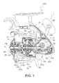
- Figure 1
- is a lateral cross-sectional view of a spinning reel according to a first embodiment of the present invention;
- Figure 2
- is a partial enlarged cross-sectional view of
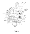
Figure 1 ; - Figure 3
- is a partial enlarged cross-sectional view of
Figure 2 ; and - Figure 4
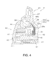
- is a partial enlarged cross-sectional view of a spinning reel according to a second embodiment of the present invention.
- As shown in
Figure 1 , a spinningreel 100 according to the first embodiment is a lever brake-type reel configured to forwardly unreel fishing line. The spinningreel 100 mainly comprises a handle 1, areel body unit 2 that rotatably supports the handle 1, arotor 3, aspool 4, adrag mechanism 30, and aseal member 50. - The handle 1 is rotatably mounted to the
reel body unit 2. The handle 1 comprises ahandle arm 38 that can be folded and ahandle grip 39 that is rotatably mounted to the distal end of thehandle arm 38. The handle 1 is attached to a master gear shaft 10, which is a rotating shaft. - As shown in
Figure 1 , thereel body unit 2 comprises a longitudinalrod mounting portion 2c that is mounted to a fishing rod, areel body 2a that is disposed to be spaced apart from therod mounting portion 2c, and aleg portion 2b that couples therod mounting portion 2c and thereel body 2a. Thereel body 2a comprises a mechanism mounting space inside. Thereel body 2a is integrally formed with theleg portion 2b, and the side is open. The opening of thereel body 2a is closed by a lid member (not shown). The rear portion of thereel body unit 2 is covered by aguard member 35. - As shown in
Figure 1 , arotor drive mechanism 5, alever brake mechanism 6, and anoscillating mechanism 20 are disposed inside of thereel body 2a. - The
rotor drive mechanism 5 is a mechanism for rotating therotor 3 in conjunction with the handle 1. As shown inFigure 1 , therotor drive mechanism 5 comprises a master gear shaft 10 to which the handle 1 is fixed so as to be integrally rotatable therewith, a master gear 11 that rotates along with the master gear shaft 10, and apinion gear 12 that meshes with the master gear 11. - The master gear shaft 10 is formed integrally with the master gear 11 and has a tubular shape. The master gear shaft 10 is rotatably supported by both the
reel body 2a and the lid member (not shown). - The master gear 11 rotates along with the master gear shaft 10. The master gear 11 is integrally formed with the master gear shaft 10. However, the master gear 11 can he separate from the master gear shaft 10.
- As shown in
Figure 1 , thepinion gear 12 is a member that meshes with the master gear 11. Thepinion gear 12 is formed in a tubular shape. Thefront portion 12a of thepinion gear 12 extends to thespool 4 side through a through-hole 3e of therotor 3. Thefront portion 12a of thepinion gear 12 is also fixed to therotor 3 via anut 13. That is, therotor 3 is integrally and rotatably fixed to thepinion gear 12 by thenut 13 in thefront portion 12a of thepinion gear 12. - Additionally, the center portion and the rear end portion in the axial direction of the
pinion gear 12 are both rotatably supported by thereel body unit 2, for example, by thereel body 2a, viaaxle bearings pinion gear 12 is also rotatably supported in the distal end portion by theaxle bearing 14c. - The
lever brake mechanism 6 is a mechanism for braking the rotation of therotor 3 in the line delivering direction (the reverse rotation). That is, thelever brake mechanism 6 is a rotor braking device. As shown inFigure 1 , thelever brake mechanism 6 comprises arotor brake unit 16, as well as abrake lever 17 for adjusting the braking force of therotor brake unit 16. Therotor brake unit 16 is disposed on the inner peripheral part of therotor 3 and brakes therotor 3. Thebrake lever 17 can switch the state of therotor brake unit 16 between a prescribed braking state in which therotor brake unit 16 brakes therotor 3 and a brake release state in which the braking of therotor brake unit 16 is released. - The
oscillating mechanism 20 operates in conjunction with the rotation of the handle 1 and reciprocally moves thespool 4 back and forth via thespool shaft 8. As shown inFigure 1 , theoscillating mechanism 20 is a traverse cam type that comprises anintermediate gear 20a, atraverse camshaft 20b, and aslider 20c. Thetraverse camshaft 20b is mounted to thereel body 2a to be rotatable around an axis that is parallel to thespool shaft 8. Theslider 20c moves along thetraverse camshaft 20b in the longitudinal direction with the rotation of thetraverse camshaft 20b. The rear end of thespool shaft 8 is non-rotatably fixed to theslider 20c. Theintermediate gear 20a is fixed to the distal end of thetraverse camshaft 20b. Theintermediate gear 20a meshes with thepinion gear 12. - The
rotor 3 is rotatably supported by thereel body unit 2. As shown inFigure 1 , therotor 3 comprises a cylindrical portion 3a, as well as afirst arm portion 3b and asecond arm portion 3c that are disposed on the sides of the cylindrical portion 3a facing each other. Aboss portion 3f having a through-hole 3e is formed in the center portion of the front wall 3d of the cylindrical portion 3a. Thespool shaft 8 and thepinion gear 12 extend through this through-hole 3e. Therotor brake unit 16 is disposed in the inner peripheral part of the cylindrical portion 3a. When thebrake lever 17 of thelever brake mechanism 16 is operated, the cylindrical portion 3a (the rotor 3) is braked via therotor brake unit 16. Abail arm 9 is pivotally disposed on the distal end of thefirst arm portion 3b and the distal end of thesecond arm portion 3c. The fishing Line is guided to thespool 4 by thebail arm 9. - As shown in
Figure 1 , thespool 4 is disposed so as to be movable back and forth in the front portion of therotor 3. Thespool 4 is disposed between thefirst arm portion 3b and thesecond arm portion 3c of therotor 3. Thespool 4 is detachably mounted to the distal end of thespool shaft 8. - As shown
Figure 2 , thespool 4 comprises aspool body 22 and a spool tube part 24.Thespool body 22 comprises a line windingcylinder part 22a, afront flange 25, arear flange 32b, and atubular portion 42b. The line windingcylinder part 22a is formed in a tubular shape. Fishing line is wound to the outer peripheral surface of the line windingcylinder part 22a. - The
front flange 25 is disposed on the front side of the line winding cylinder part 22a.Thefront flange 25 extends radially outward from the front end portion of the line windingcylinder part 22a. Thefront flange 25 comprises aflange portion 27 and a connectingportion 28. Theflange portion 27 is a portion that extends in a direction away from thespool shaft 8. Theflange portion 27 is formed in an essentially annular shape. - As shown in
Figure 2 , the connectingportion 28 is a portion that connects the line windingcylinder part 22a and theflange portion 27. The connectingportion 28 is integrally formed with the line windingcylinder part 22a and theflange portion 27. The connectingportion 28 comprises an abuttingplane 28a. The abuttingplane 28a can abut the distal end side rear surface of theseal member 50, for example, the rear surface of aninclined portion 52b, as mentioned below. The abuttingplane 28a is formed on the inner peripheral side of the connectingportion 28. The abuttingplane 28a is formed in the circumferential direction on the inner peripheral surface of the connectingportion 28. Additionally, the abuttingplane 28a is inclined from the front surface of theflange portion 27 toward the inner peripheral surface of the line windingcylinder part 22a. - At least one of the
flange portion 27 and the connectingportion 28 comprises aprojection 29. In one embodiment theprojection 29 is formed in theflange portion 27. Theprojection 29 protrudes forward from theflange portion 27 and is formed in an annular shape in the circumferential direction. Abent portion 29a that is bent toward thespool shaft 8 is formed in the distal end portion of theprojection 29. Thebent portion 29a is integrally formed with theprojection 29 in an annular shape in the distal end portion of theprojection 29. - As shown in
Figure 2 , therear flange 32b is disposed on the rear end portion of the line windingcylinder part 22a. Additionally, therear flange 32b extends radially outward from the rear end portion of the line windingcylinder part 22a. Thetubular portion 42b is a portion that extends rearward from the outer peripheral part of therear flange 32b. Thetubular portion 42b has a larger in diameter than the line windingcylinder part 22a. Thetubular portion 42b is integrally formed with therear flange 32b so as to cover the cylindrical portion 3a of therotor 3. - As shown in
Figure 2 , thespool tube part 24 is non-rotatably and detachably mounted to thespool shaft 8. Thespool tube part 24 is able to detach thespool body 22 and thedrag mechanism 30 from thespool shaft 8. - As shown in
Figure 2 , thedrag mechanism 30 brakes the rotation of thespool 4. Thedrag mechanism 30 comprises adrag adjuster 40 that is mounted to the distal end of thespool shaft 8, a pressingmember 60 that is pressed by thedrag adjuster 40, and a spool brake unit 62 (one example of a braking member) that is pressed by the pressingmember 60 and brakes thespool 4. - As shown in
Figure 3 , thedrag adjuster 40 comprises anadjustment knob 41, anut 43, an abuttingmember 44, and a fixingmember 45. Theadjustment knob 41 is for adjusting the frictional coupling force of thespool braking unit 62. Theadjustment knob 41 is mounted on the distal end portion of thespool shaft 8. In particular, theadjustment knob 41 is mounted on thespool tube part 24 via thenut 43. For example theadjustment knob 41 is mounted on thenut 43 in order to be relatively non-rotatable and can move in the axial direction along thespool tube part 24 along with thenut 43. Also, as discussed above, thespool tube part 24 is non-rotatably and detachably mounted to the distal end portion of thespool shaft 8. Thus, theadjustment knob 41 is detachable from the distal end portion of thespool shaft 8 via thenut 43 and thespool tube part 24. - The
adjustment knob 41 comprises aboss portion 46. A threadedportion 45a (as mentioned below) of the fixingmember 45 is screwed to theboss portion 46. In particular, theboss portion 46 comprises aboss body section 46a (one example for a body section) and a large-diameter section 46b that is provided to the outer periphery of theboss body portion 46a. Theboss body section 46a is formed in an essentially tubular shape. A female threadedpart 46c is formed in the inner peripheral part of theboss body section 46a. A threadedportion 45a (the male threaded portion) of the fixingmember 45 is screwed into this female threadedpart 46c. - The
nut 43 is mounted to theadjustment knob 41 in order to be relatively non-rotatable and relatively movable in the axial direction. The female threadedpart 43a is formed on the inner peripheral surface of thenut 43, and this female threadedpart 43a is screwed to the male threadedportion 24a of thespool tube part 24. Accordingly, when theadjustment knob 41 is rotated, thenut 43 rotates along with theadjustment knob 41 and moves along thespool tube part 24. - The abutting
member 44 is disposed on theadjustment knob 41 and can abut the front surface of theseal member 50. The abuttingmember 44 comprises a body portion 44a, an abuttingportion 44b, and a holdingportion 44c. The abuttingportion 44b is integrally formed with the body portion 44a. The abuttingportion 44b protrudes outward from the body portion 44a in a cylindrical shape. The distal end of the abuttingportion 44b can abut the distal end side front surface of theseal member 50, for example, the front surface of aninclined portion 52b, as mentioned below. Theboss portion 46 of theadjustment knob 41 is inserted into the holdingportion 44c. The holdingportion 44c is held by theadjustment knob 41 and the fixingmember 45. In particular, the holdingportion 44c is held by the large-diameter section 46b of theadjustment knob 41 and thehead portion 45b (as mentioned below) of the fixingmember 45. - The fixing
member 45 is a member for fixing the abuttingmember 44 to theadjustment knob 41. The fixingmember 45 comprises a threadedportion 45a and ahead portion 45b. For example, the threadedportion 45a is a male threaded portion. Thehead portion 45b is formed to be larger in diameter than the threadedportion 45a. - The pressing
member 60 is disposed between thedrag adjuster 40 of thedrag mechanism 30 and thespool braking unit 62 of thedrag mechanism 30. The pressingmember 60 is pressed by thedrag adjuster 40 via aspring member 61. Specifically, as described above, when theadjustment knob 41 rotates, thenut 43 rotates along with theadjustment knob 41 and moves along thespool tube part 24. Then, thespring member 61 is pressed by thenut 43, and the pressingmember 60 is pressed by thisspring member 61. Next, the pressingmember 60 moves along thespool tube part 24, and thespool braking unit 62 is pressed. - The pressing
member 60 also functions as a member tor supporting theseat member 50. Anannular groove 60a is formed on the outer peripheral part of the pressingmember 60, and theseal member 50 is disposed in theannular groove 60a. Therefore, when theadjustment knob 41 is rotated and the pressingmember 60 moves along thespool tube part 24, theseal member 50 also moves along thespool tube part 24 along with the pressingmember 60. - As shown in
Figure 2 , thespool braking unit 62 is housed inside of thespool 4 and brakes the rotation of thespool 4. Thespool braking unit 62 is configured by a plurality of friction members. When theadjustment knob 41 is operated, the frictional coupling force of the plurality of friction members is adjusted, and the braking force with respect to the rotation of thespool 4 is adjusted. Specifically, when theadjustment knob 41 is rotated in a first direction, the frictional coupling force of the plurality of friction members increases, and the braking force during the rotation of thespool 4 increases. Meanwhile, when theadjustment knob 41 is rotated in a second direction, which is the opposite of the first direction, the frictional coupling force of the plurality of friction members decreases, and the braking force during the rotation of thespool 4 decreases. Accordingly, the braking force during the rotation of thespool 4 is adjusted. - As shown in
Figure 2 andFigure 3 , theseal member 50 is mounted to thespool tube part 24. Specifically, theseal member 50 is mounted to thespool tube part 24 via the pressingmember 60 of thedrag mechanism 30. That is, theseal member 50 is mounted to thespool shaft 8 via the pressingmember 60 and thespool tube part 24. - The
seal member 50 is elastically deformable. Theseal member 50 protrudes from thedrag adjuster 40 side toward the spool side so as to close a space that is formed between thespool 4 and thedrag adjuster 40. Theseal member 50 can abut thefront flange 25. For example, in one embodiment, theseal member 50 abuts theprojection 29 of thefront flange 25. Additionally, theseal member 50 can abut thedrag adjuster 40. For example, in one embodiment, theseal member 50 can abut the abuttingmember 44 of thedrag adjuster 40. - Specifically, as shown in
Figure 3 , theseal member 50 comprises a mountingportion 51 and aseal portion 52 that extend outward from the mountingportion 51. The mountingportion 51 is formed in a cylindrical shape. The inner peripheral part of the mountingportion 51 is mounted to the outer peripheral part of the pressingmember 60. For example, in one embodiment, the inner peripheral part of the mountingportion 51 is mounted to theannular groove 60a of the pressingmember 60. - The
seal portion 52 is integrally formed on the outer peripheral part of the mountingportion 51 theseal portion 52 is formed in an essentially annular plate shape. The distal end portion of theseal member 50 abuts theprojection 29 of thefront flange 25. The distal end side rear surface of theseal member 50 abuts thefront flange 25. The distal end side front surface of theseal member 50 also abuts the abuttingmember 44. - Specifically, the
seal member 52 comprises aproximal end portion 52a and aninclined portion 52b. Theproximal end portion 52a is a portion that extends radially outward (in a direction away from the spool shaft) from the mountingportion 51. Theinclined portion 52b is a portion that extends while inclining forward from theproximal end portion 52a. In one embodiment, the distal end of theinclined portion 52b abuts theprojection 29 that is formed in theflange portion 27 of thefront flange 25. Additionally, the distal end of theinclined portion 52b is disposed between thebent portion 29a of theprojection 29 and thefront flange 25 in a direction along thespool shaft 8. The front surface of theinclined portion 52b also abuts the abuttingportion 44b of the abuttingmember 44. - Additionally, a prescribed gap is formed between the rear surface of the
inclined portion 52b and the abuttingplane 28a of the connectingportion 28. InFigure 2 andFigure 3 , the prescribed gap is formed between the rear surface of theinclined portion 52b and the abuttingplane 28a of the connectingportion 28; however, the rear surface of theinclined portion 52b can abut the abuttingplane 28a of the connectingportion 28 of thefront flange 25. For example, when thedrag adjuster 40 is operated and thedrag adjuster 40 approaches thespool 4, the rear surface of theinclined portion 52b abuts the abuttingplane 28a of the connectingportion 28 of thefront flange 25. However, when thedrag adjuster 40 is disposed in a state in which the above-described gap has been formed, and an external force acts on the front surface of theinclined portion 52b, theinclined portion 52b is elastically deformed toward the front side flange and is able to abut the abuttingplane 28a of the connectingportion 28 of thefront flange 25. Accordingly, the intrusion of foreign matter inside of the line windingcylinder part 22a can be reliably prevented. Furthermore, the front surface of theinclined portion 52b of theseal member 52 abuts the abutting member 44 (the abuttingportion 44b) of thedrag adjuster 40, so that the intrusion of foreign matter inside of thedrag adjuster 40 is also prevented. - The
present spinning reel 100 is a reel that forwardly unreels fishing line. Thepresent spinning reel 100 comprises areel body unit 2, aspool shaft 8, aspool 4, adrag mechanism 30, and aseal member 50. Thespool shaft 8 is supported by thereel body unit 2 so as to be movable longitudinally. Thespool 4 is attached to thespool shaft 8. Thespool 4 comprises a line windingcylinder part 22a and afront flange 25. Fishing line can be wound to the outside of the line windingcylinder part 22a. Thefront flange 25 is disposed on the front side of the line windingcylinder part 22a. - The
drag mechanism 30 comprises aspool braking unit 62 and adrag adjuster 40. Thespool braking unit 62 is housed inside of thespool 4 and brakes the rotation of thespool 4. Thedrag adjuster 40 is attached to the distal end of thespool shaft 8 and adjusts the frictional coupling force of thespool braking unit 62. Theseal member 50 is elastically deformable. Theseal member 50 protrudes from thedrag adjuster 40 side toward thefront flange 25 so as to close a space that is formed between thefront flange 25 and thedrag adjuster 40. Theseal member 50 can abut thefront flange 25 that is provided to the front side of the line windingcylinder part 22a. - In the
present spinning reel 100, the space that is formed between thefront flange 25 and thedrag adjuster 40 is closed with theseal member 50 abutting thefront flange 25. Accordingly, in thepresent spinning reel 100, theseal member 50 abuts thefront flange 25; therefore, it is not necessary to form a space for disposing theentire seal member 50 inside of the line windingcylinder part 22a of thespool 4. Therefore, when compared to conventional technology, the outer diameter of the line windingcylinder part 22a of thespool 4 can be small, and sufficient fishing line can be wound to thespool 4. That is, a spinning reel is provided that can sufficiently wind fishing line to thespool 4. - In the
present spinning reel 100, thefront flange 25 disposed on the front side of the line windingcylinder part 22a comprises aflange portion 27 that extends in a direction away from thespool shaft 8 and a connectingportion 28 that connects the line windingcylinder part 22a and theflange portion 27. At least either theflange portion 27 or the connectingportion 28 comprises aprojection 29. The distal end portion of theseal member 50 can abut theprojection 29. - In this configuration, since the distal end portion of the
seal member 50 can abut theprojection 29 of at least one of theflange portion 27 and the connectingportion 28, the intrusion of foreign matter inside of thespool 4 can be reliably prevented. - In the
present spinning reel 100, theprojection 29 protrudes forward from at least one of theflange portion 27 and the connectingportion 28. - In this configuration, since the distal end portion of the
seal member 50 can abut aprojection 29 that protrudes forward from at least one of theflange portion 27 and the connectingportion 28, the intrusion of foreign matter along theflange portion 27 and/or the connecting portion can be reliably prevented. - In the
present spinning reel 100, the distal end portion of theprojection 29 is bent toward thespool shaft 8. - In this configuration, the distal end portion of the
seal member 50 can be disposed between the part where the distal end portion of theprojection 29 is bent and at least one of theflange portion 27 and the connectingportion 28, so that the distal end portion of theseal member 50 can be covered by theprojection 29. Accordingly, the distal end portion of theseal member 50 can be protected, and the intrusion of foreign matter along theflange portion 27 and/or the connectingportion 28 can be more prevented. - In the
present spinning reel 100, the distal end side rear surface of theseal member 50 can abut thefront flange 25 that is disposed on the front side of the line windingcylinder part 22a. - In this configuration, the distal end side rear surface of the
seal member 50 can be in surface contact with thefront flange 25. Thus, the intrusion of foreign matter can be reliably prevented with theseal member 50. That is, a spinningreel 100 is provided that can reliably prevent the intrusion of foreign matter inside of thespool 4. - In the
present spinning reel 100, thefront flange 25 comprises aflange portion 27 and a connectingportion 28. Theflange portion 27 is a portion that extends in a direction away from the spool shaft K. The connectingportion 28 is a portion that connects the line windingcylinder part 22a and theflange portion 27. The connectingportion 28 comprises an abuttingplane 28a that can abut the distal end side rear surface of theseal member 50. - In this configuration, the distal end side rear surface of the
seal member 50 can be in surface contact with the abuttingplane 28a of the connectingportion 28. Thus, the intrusion of foreign matter can be reliably prevented with theseal member 50. - In the
present spinning reel 100, thedrag adjuster 40 comprises anadjustment knob 41, anut 43, an abuttingmember 44, and a fixingmember 45. Theadjustment knob 41 is screwed to the distal end of thespool shaft 8. The abuttingmember 44 is disposed on theadjustment knob 41 and can abut the front surface of theseal member 50. The fixingmember 45 fixes the abuttingmember 44 to theadjustment knob 41. - In this configuration, the intrusion of foreign matter inside of the
drag adjuster 40 can be prevented by abutting the abuttingmember 44 of thedrag adjuster 40 to the front surface of theseal member 50. - In the
present spinning reel 100, the fixingmember 45 comprises a threadedportion 45a and ahead portion 45b. Theadjustment knob 41 comprises aboss portion 46 to which the threadedportion 45a is screwed. The abuttingmember 44 comprises a holdingportion 44c to which theboss portion 46 is inserted and that is held by theadjustment knob 41 and thehead portion 45b. - In this configuration, the
boss portion 46 of theadjustment knob 41 is inserted into the holdingportion 44c of the abuttingmember 44. In this state, the holdingportion 44c of the abuttingmember 44 is held by theadjustment knob 41 and thehead portion 45b. Accordingly, since the threadedportion 45a of the fixingmember 45 can be screwed into theboss portion 46 of theadjustment knob 41 on thehead portion 45b side, theboss portion 46 of theadjustment knob 41 can be short. That is, it is possible to reduce the size of thedrag adjuster 40, and theseal member 50 can abut at least one of thefront flange 25 and the connectingportion 28. - In the
present spinning reel 100, theboss portion 46 comprises aboss body section 46a and a large-diameter section 46b that is disposed on the outer periphery of theboss body section 46a. The holdingportion 44c is held by thehead portion 45b and the large-diameter section 46b. - In this configuration, the holding
portion 44c of the abuttingmember 44 is held by thehead portion 45b of the fixingmember 45 and the large-diameter section 46b of theboss portion 46 of theadjustment knob 41, so that the abuttingmember 44 can be securely fixed to theadjustment knob 41 by the fixingmember 45. - In the spinning reel according to the second embodiment, the way in which the
seal member 50 abuts thespool 4 differs from the first embodiment. Therefore, the configuration of theseal member 50 and the configuration of thespool 4 will be explained regarding the parts that are different form the first embodiment; the explanations regarding the configurations that are the same as those in the first embodiment will be simplified or have been omitted. Additionally, the explanations regarding the configurations besides theseal member 50 and thespool 4 have been omitted. The explanations of the configurations also omitted here shall be pursuant to the configurations of the first embodiment. Moreover, inFigure 4 , the configurations that are the same as those in the first embodiment have been given the same numbers. - As shown in
Figure 4 , thespool 4 comprises aspool body 22 and aspool tube part 24. Thespool tube part 24 is configured in the same way as in the first embodiment, so the explanation thereof has been omitted here. - The
spool body 22 comprises a line windingcylinder part 22a, a front flange 25 (one example of a flange), a rear flange 32h (refer toFigure 1 ), and atubular portion 42b (refer toFigure 1 ). Thefront flange 25 comprises aflange portion 27 and a connectingportion 28. The inner peripheral part of theflange portion 27 comprises a first abuttingplane 27a that theseal member 50 abuts. The connectingportion 28 comprises a secondabutting plane 28a (one example of an abutting plane). The secondabutting plane 28a abuts the distal end side rear surface of theseal member 50. The secondabutting plane 28a is formed along the inner peripheral surface of the connectingportion 28 in the circumferential direction. Additionally, the second abuttingplane 28a is inclined from the front surface of theflange portion 27 toward the inner peripheral surface of the line windingcylinder part 22a. Further, therear flange 32b and thetubular portion 42b are configured in the same way as in the first embodiment, so their explanations have been omitted here. - The
seal member 50 is elastically deformable. As shown inFigure 4 , theseal member 50 protrudes from thedrag adjuster 40 side toward thespool 4 side so as to close a space that is formed between thespool 4 and thedrag adjuster 40. Theseal member 50 can abut thefront flange 25. Specifically, theseal member 50 abuts theflange portion 27 on thefront flange 25. - The
seal member 50 is mounted to thespool tube part 24. Specifically, theseal member 50 is mounted to the spool tube part 24v1 a the pressingmember 60 of thedrag mechanism 30. That is, theseal member 50 is mounted to thespool shaft 8 via the pressingmember 60 and thespool tube part 24. - The
seal member 50 comprises a mountingportion 51 and aseal portion 52 that extends outward from the mountingportion 51. The mountingportion 51 is formed in a cylindrical shape, and the inner peripheral part of the mountingportion 51 is mounted to the outer peripheral part of the pressingmember 60. Theseal portion 52 is integrally formed on the outer peripheral part of the mountingportion 51. Theseal portion 52 is formed in an essentially annular plate shape. The distal end portion of theseal member 50 and the distal end side rear surface of theseal member 50 abut thefront flange 25. - Specifically, the
seal member 52 comprises aproximal end portion 52a and aninclined portion 52b. Theproximal end portion 52a is a portion that extends radially outward from the mountingportion 51. Theinclined portion 52b is a portion that extends while inclining forward from theproximal end portion 52a. In one embodiment, the distal end of theinclined portion 52b abuts the first abuttingplane 27a of theflange portion 27 of thefront flange 25. Additionally, the rear surface of theinclined portion 52b can abut a secondabutting plane 28a of the connectingportion 28 of thefront flange 25. For example, when thedrag adjuster 40 is operated and thedrag adjuster 40 approaches thespool 4, the rear surface of theinclined portion 52b can abut the second abuttingplane 28a of the connectingportion 28 of thefront flange 25. However, when thedrag adjuster 40 is disposed in a state in which the above-described gap is formed, and an external force acts on the front surface of theinclined portion 52b, theinclined portion 52b is elastically deformed toward thefront flange 25 and is able to abut the second abuttingplane 28a of the connectingportion 28 of thefront flange 25. Accordingly, the intrusion of foreign matter inside of the line windingcylinder part 22a can be reliably prevented. Moreover, the front surface of theinclined portion 52b of the seal member abuts the abutting member 44 (the abuttingportion 44b) of thedrag adjuster 40 in the same way as in the first embodiment; therefore, the intrusion of foreign matter inside of thedrag adjuster 40 is also prevented. - In the above-described first embodiment, an example is explained in which the
bent portion 29a is formed in theprojection 29 of thefront flange 25. However, as long as the seal member 50 (the distal end of theinclined portion 52b) can abut theprojection 29, thebent portion 29a does not necessarily have to be formed in theprojection 29. - In the above-described first embodiment, an example is explained in which the
projection 29 is formed in theflange portion 27. However, theprojection 29 can be formed in any way as long as thisprojection 29 is formed in thefront flange 25. For example, theprojection 29 can be formed in the connectingportion 28. Theprojection 29 can also be formed to straddle theflange portion 27 and the connectingportion 28. - In the above-described second embodiment an example is explained in which the
flange portion 27 is thick, and the seal member 50 (the distal end of theinclined portion 52b) abuts theflange portion 27. Instead of the above, the outer peripheral side of the connectingportion 28 can be partially thick, and a first abuttingplane 27a, as shown inFigure 4 , can be fanned. Additionally, the first abuttingplane 27a can be formed to straddle theflange portion 27 and the connectingportion 28. - In the first and the second embodiments, a lever brake-type spinning reel is used as an example for the explanation; however, the spinning reel can also be a non-lever brake-type reel.
- The present invention can be widely applied to a spinning reel.
Claims (9)
- A spinning reel (100) for forwardly casting a fishing line, comprising:a reel body unit (2);a spool shaft (8) having a distal end and being supported by the reel body unit (2) so as to be movable longitudinally;a spool (4) including a line winding cylinder part (22a) having a front side, and a front flange (25) disposed on the front side of the line winding cylinder part (22a) and being attached to the spool shaft (8), the line winding cylinder part (22a) being configured to have the fishing line wound to an outside thereof;a drag mechanism (30) comprising a braking member (62) housed inside of the spool (4) and being configured to brake a rotation of the spool (4), and a drag adjuster (40) attached to the distal end of the spool shaft (8) and being configured to adjust a frictional coupling force of the braking member (62); anda seal member (50) having a drag adjuster side and being configured to be elastically deformed, the seal member (50) protruding from the drag adjuster side toward the front flange (25) so as to seal a space formed between the front flange (25) and the drag adjuster (40), and being configured to abut the front flange (25).
- The spinning reel (100) recited in claim 1, wherein the front flange (25) comprises a flange portion (27) extending in a radial direction away from the spool shaft (8) and a connecting portion (28) connecting the line winding cylinder part (22a) and the flange portion (27), at least one of the flange portion (27) and the connecting portion (28) comprises a projection (29), and a distal end portion of the seal member (50) is configured to abut the projection (29).
- The spinning reel (100) recited in claim 2, wherein the projection (29) protrudes forward from the at least one of the flange portion (27) and the connecting portion (28).
- The spinning reel (100) recited in claim 2 or 3, wherein a distal end portion of the projection (29) is bent toward the spool shaft (8).
- The spinning reel (100) recited in claims 1 to 4, wherein a distal end side rear surface of the seal member (50) abuts the front flange (25).
- The spinning reel (100) recited in claim 5, wherein the front flange (25) comprises a flange portion (27) extending in a radial direction away from the spool shaft (8) and a connecting portion (28) connecting the line winding cylinder part (22a) and the flange portion (27), and the connecting portion (28) comprises an abutting plane (28a) abutting the distal end side rear surface of the seal member (50).
- The spinning reel (100) recited in claims 1 to 6, wherein the drag adjuster (40) comprises an adjustment knob (41) screwed into a distal end of the spool shaft (8), an abutting member (44) disposed in the adjustment knob (41) and being configured to abut a front surface of the seal member (50), and a fixing member (45) fixing the abutting member (44) to the adjustment knob (41).
- The spinning reel (100) recited in claim 7, wherein the fixing member (45) comprises a threaded portion (45a) and a head portion (45b), the adjustment knob (41) comprises a boss portion (46) to which the threaded portion (45a) is screwed, and the abutting member (44) comprises a holding portion (44c) into which the boss portion (46) is inserted and that is held by the adjustment knob (41) and the head portion (45b).
- The spinning reel (100) recited in claim 8, wherein the boss portion (46) comprises a body section (46a) and a large-diameter section (46b) disposed on an outer periphery of the body section (46a), and the holding portion (44c) is held by the head portion (45b) and the large-diameter section (46b).
Applications Claiming Priority (1)
| Application Number | Priority Date | Filing Date | Title |
|---|---|---|---|
| JP2013238561A JP6352618B2 (en) | 2013-11-19 | 2013-11-19 | Spinning reel |
Publications (2)
| Publication Number | Publication Date |
|---|---|
| EP2880975A1 true EP2880975A1 (en) | 2015-06-10 |
| EP2880975B1 EP2880975B1 (en) | 2018-01-03 |
Family
ID=51900819
Family Applications (1)
| Application Number | Title | Priority Date | Filing Date |
|---|---|---|---|
| EP14193782.1A Active EP2880975B1 (en) | 2013-11-19 | 2014-11-19 | Spinning reel |
Country Status (7)
| Country | Link |
|---|---|
| US (1) | US9510576B2 (en) |
| EP (1) | EP2880975B1 (en) |
| JP (1) | JP6352618B2 (en) |
| KR (1) | KR102243482B1 (en) |
| CN (1) | CN104642271B (en) |
| MY (1) | MY177734A (en) |
| TW (1) | TWI623263B (en) |
Families Citing this family (5)
| Publication number | Priority date | Publication date | Assignee | Title |
|---|---|---|---|---|
| JP6856355B2 (en) * | 2016-11-08 | 2021-04-07 | 株式会社シマノ | Waterproof structure of fishing reel |
| JP7065626B2 (en) * | 2018-01-31 | 2022-05-12 | 株式会社シマノ | Drag knob |
| JP7166095B2 (en) * | 2018-07-19 | 2022-11-07 | シマノコンポネンツ マレーシア エスディーエヌ.ビーエッチディー. | spinning reel |
| CN111820200B (en) * | 2020-07-13 | 2021-12-14 | 山东环球渔具股份有限公司 | Connecting structure of fishing line reel |
| JP7778524B2 (en) * | 2021-10-15 | 2025-12-02 | 株式会社シマノ | Spinning reel |
Citations (4)
| Publication number | Priority date | Publication date | Assignee | Title |
|---|---|---|---|---|
| US6149089A (en) * | 1998-02-26 | 2000-11-21 | Daiwa Seiko, Inc. | Fishing spinning reel |
| JP2002204640A (en) | 2001-01-10 | 2002-07-23 | Shimano Inc | Spinning reel spool |
| US20090272831A1 (en) * | 2008-04-30 | 2009-11-05 | Shimano Inc. | Spool for spinning reel |
| EP2258167A1 (en) * | 2009-06-02 | 2010-12-08 | Shimano Components (Malaysia) SDN BHD | Spinning Reel Drag Knob |
Family Cites Families (16)
| Publication number | Priority date | Publication date | Assignee | Title |
|---|---|---|---|---|
| US5149008A (en) * | 1990-12-21 | 1992-09-22 | Shimano Industrial Co., Ltd. | Spinning reel with adjustable drag member |
| JP2000333567A (en) * | 1999-05-27 | 2000-12-05 | Daiwa Seiko Inc | Spinning reel for fishing |
| TW440425B (en) * | 1999-07-14 | 2001-06-16 | Shimano Kk | Rotor drive for spinning reel and spinning reel |
| JP3616300B2 (en) * | 2000-03-30 | 2005-02-02 | ダイワ精工株式会社 | Fishing spinning reel |
| JP3961757B2 (en) * | 2000-09-29 | 2007-08-22 | 株式会社シマノ | Parts support structure for fishing reel |
| TW518203B (en) | 2001-01-10 | 2003-01-21 | Shimano Kk | Spool of spinning reel |
| TW518205B (en) * | 2001-02-23 | 2003-01-21 | Shimano Kk | Spool of spinning reel |
| JP2004147561A (en) * | 2002-10-30 | 2004-05-27 | Daiwa Seiko Inc | Spinning reel for fishing |
| US7175121B2 (en) * | 2003-10-28 | 2007-02-13 | Shimano Inc. | Spinning reel sounding mechanism |
| JP2006217848A (en) * | 2005-02-09 | 2006-08-24 | Shimano Inc | Handle assembly for spinning reel |
| US7232087B2 (en) * | 2005-04-15 | 2007-06-19 | Shimano Inc. | Spinning reel drag mechanism |
| SG144041A1 (en) * | 2006-12-21 | 2008-07-29 | Shimano Kk | Reel unit of spinning reel |
| JP4484887B2 (en) * | 2007-02-07 | 2010-06-16 | グローブライド株式会社 | Fishing spinning reel |
| JP4943401B2 (en) * | 2007-12-18 | 2012-05-30 | 株式会社シマノ | Fishing reel guide mechanism for spinning reel |
| JP5746462B2 (en) * | 2009-08-20 | 2015-07-08 | 株式会社シマノ | Spinning reel spool connection structure |
| JP5349348B2 (en) * | 2010-01-22 | 2013-11-20 | 株式会社シマノ | Spool support structure for spinning reel |
-
2013
- 2013-11-19 JP JP2013238561A patent/JP6352618B2/en active Active
-
2014
- 2014-06-17 KR KR1020140073750A patent/KR102243482B1/en active Active
- 2014-07-09 TW TW103123695A patent/TWI623263B/en active
- 2014-10-22 US US14/520,709 patent/US9510576B2/en active Active
- 2014-11-14 MY MYPI2014703398A patent/MY177734A/en unknown
- 2014-11-19 CN CN201410661060.8A patent/CN104642271B/en active Active
- 2014-11-19 EP EP14193782.1A patent/EP2880975B1/en active Active
Patent Citations (4)
| Publication number | Priority date | Publication date | Assignee | Title |
|---|---|---|---|---|
| US6149089A (en) * | 1998-02-26 | 2000-11-21 | Daiwa Seiko, Inc. | Fishing spinning reel |
| JP2002204640A (en) | 2001-01-10 | 2002-07-23 | Shimano Inc | Spinning reel spool |
| US20090272831A1 (en) * | 2008-04-30 | 2009-11-05 | Shimano Inc. | Spool for spinning reel |
| EP2258167A1 (en) * | 2009-06-02 | 2010-12-08 | Shimano Components (Malaysia) SDN BHD | Spinning Reel Drag Knob |
Also Published As
| Publication number | Publication date |
|---|---|
| KR102243482B1 (en) | 2021-04-22 |
| KR20150057942A (en) | 2015-05-28 |
| CN104642271B (en) | 2018-11-16 |
| CN104642271A (en) | 2015-05-27 |
| JP2015097492A (en) | 2015-05-28 |
| JP6352618B2 (en) | 2018-07-04 |
| US9510576B2 (en) | 2016-12-06 |
| EP2880975B1 (en) | 2018-01-03 |
| US20150136889A1 (en) | 2015-05-21 |
| MY177734A (en) | 2020-09-23 |
| TWI623263B (en) | 2018-05-11 |
| TW201519759A (en) | 2015-06-01 |
Similar Documents
| Publication | Publication Date | Title |
|---|---|---|
| KR102395200B1 (en) | Dual-bearing reel and reel unit for same | |
| KR102061077B1 (en) | A spool brake device for dual-bearing reel and a dual-bearing reel | |
| US9510576B2 (en) | Spinning reel | |
| KR102689222B1 (en) | Dual bearing fishing reel | |
| KR101201670B1 (en) | Spinning reel | |
| CN107801700B (en) | Dual-bearing reel | |
| KR102228645B1 (en) | Roller clutch for fishing reel and spinning reel using the same | |
| JP2016002062A (en) | Double bearing reel and double bearing reel clutch mechanism | |
| KR20040068020A (en) | Level winding mechanism for a dual bearing reel | |
| US6857589B2 (en) | Fishing reel component | |
| JP2015097492A5 (en) | ||
| US10617101B2 (en) | Fishing reel | |
| TWI661772B (en) | Dual-bearing fishing reel | |
| JP6315689B2 (en) | Fishing reel | |
| KR102662295B1 (en) | Drag knob, and fishing reel | |
| KR20200010018A (en) | Spinning reel | |
| JP2010158184A (en) | Handle-mounting structure for spinning reel | |
| KR20040007267A (en) | Stand Device for Spinning Reel | |
| US6983905B2 (en) | Fishing reel screw operation structure | |
| CN106857436B (en) | Rotor of spinning reel and spinning reel | |
| JP2012170434A (en) | Double bearing reel | |
| JP6693921B2 (en) | Drive gear | |
| JP2004081154A (en) | Line guiding mechanism of spinning reel | |
| JP2012170432A (en) | Double bearing reel | |
| JP2011177117A (en) | Fishing line guide mechanism of spinning reel |
Legal Events
| Date | Code | Title | Description |
|---|---|---|---|
| PUAI | Public reference made under article 153(3) epc to a published international application that has entered the european phase |
Free format text: ORIGINAL CODE: 0009012 |
|
| 17P | Request for examination filed |
Effective date: 20141119 |
|
| AK | Designated contracting states |
Kind code of ref document: A1 Designated state(s): AL AT BE BG CH CY CZ DE DK EE ES FI FR GB GR HR HU IE IS IT LI LT LU LV MC MK MT NL NO PL PT RO RS SE SI SK SM TR |
|
| AX | Request for extension of the european patent |
Extension state: BA ME |
|
| R17P | Request for examination filed (corrected) |
Effective date: 20150805 |
|
| RBV | Designated contracting states (corrected) |
Designated state(s): AL AT BE BG CH CY CZ DE DK EE ES FI FR GB GR HR HU IE IS IT LI LT LU LV MC MK MT NL NO PL PT RO RS SE SI SK SM TR |
|
| 17Q | First examination report despatched |
Effective date: 20161005 |
|
| GRAP | Despatch of communication of intention to grant a patent |
Free format text: ORIGINAL CODE: EPIDOSNIGR1 |
|
| RIC1 | Information provided on ipc code assigned before grant |
Ipc: A01K 89/027 20060101ALI20170925BHEP Ipc: A01K 89/01 20060101AFI20170925BHEP |
|
| INTG | Intention to grant announced |
Effective date: 20171018 |
|
| GRAS | Grant fee paid |
Free format text: ORIGINAL CODE: EPIDOSNIGR3 |
|
| GRAA | (expected) grant |
Free format text: ORIGINAL CODE: 0009210 |
|
| AK | Designated contracting states |
Kind code of ref document: B1 Designated state(s): AL AT BE BG CH CY CZ DE DK EE ES FI FR GB GR HR HU IE IS IT LI LT LU LV MC MK MT NL NO PL PT RO RS SE SI SK SM TR |
|
| REG | Reference to a national code |
Ref country code: GB Ref legal event code: FG4D |
|
| REG | Reference to a national code |
Ref country code: CH Ref legal event code: EP Ref country code: AT Ref legal event code: REF Ref document number: 959402 Country of ref document: AT Kind code of ref document: T Effective date: 20180115 |
|
| REG | Reference to a national code |
Ref country code: IE Ref legal event code: FG4D |
|
| REG | Reference to a national code |
Ref country code: DE Ref legal event code: R096 Ref document number: 602014019325 Country of ref document: DE |
|
| REG | Reference to a national code |
Ref country code: NL Ref legal event code: MP Effective date: 20180103 |
|
| REG | Reference to a national code |
Ref country code: LT Ref legal event code: MG4D |
|
| REG | Reference to a national code |
Ref country code: AT Ref legal event code: MK05 Ref document number: 959402 Country of ref document: AT Kind code of ref document: T Effective date: 20180103 |
|
| PG25 | Lapsed in a contracting state [announced via postgrant information from national office to epo] |
Ref country code: NL Free format text: LAPSE BECAUSE OF FAILURE TO SUBMIT A TRANSLATION OF THE DESCRIPTION OR TO PAY THE FEE WITHIN THE PRESCRIBED TIME-LIMIT Effective date: 20180103 |
|
| PG25 | Lapsed in a contracting state [announced via postgrant information from national office to epo] |
Ref country code: LT Free format text: LAPSE BECAUSE OF FAILURE TO SUBMIT A TRANSLATION OF THE DESCRIPTION OR TO PAY THE FEE WITHIN THE PRESCRIBED TIME-LIMIT Effective date: 20180103 Ref country code: NO Free format text: LAPSE BECAUSE OF FAILURE TO SUBMIT A TRANSLATION OF THE DESCRIPTION OR TO PAY THE FEE WITHIN THE PRESCRIBED TIME-LIMIT Effective date: 20180403 Ref country code: ES Free format text: LAPSE BECAUSE OF FAILURE TO SUBMIT A TRANSLATION OF THE DESCRIPTION OR TO PAY THE FEE WITHIN THE PRESCRIBED TIME-LIMIT Effective date: 20180103 Ref country code: HR Free format text: LAPSE BECAUSE OF FAILURE TO SUBMIT A TRANSLATION OF THE DESCRIPTION OR TO PAY THE FEE WITHIN THE PRESCRIBED TIME-LIMIT Effective date: 20180103 Ref country code: FI Free format text: LAPSE BECAUSE OF FAILURE TO SUBMIT A TRANSLATION OF THE DESCRIPTION OR TO PAY THE FEE WITHIN THE PRESCRIBED TIME-LIMIT Effective date: 20180103 Ref country code: CY Free format text: LAPSE BECAUSE OF FAILURE TO SUBMIT A TRANSLATION OF THE DESCRIPTION OR TO PAY THE FEE WITHIN THE PRESCRIBED TIME-LIMIT Effective date: 20180103 |
|
| PG25 | Lapsed in a contracting state [announced via postgrant information from national office to epo] |
Ref country code: LV Free format text: LAPSE BECAUSE OF FAILURE TO SUBMIT A TRANSLATION OF THE DESCRIPTION OR TO PAY THE FEE WITHIN THE PRESCRIBED TIME-LIMIT Effective date: 20180103 Ref country code: SE Free format text: LAPSE BECAUSE OF FAILURE TO SUBMIT A TRANSLATION OF THE DESCRIPTION OR TO PAY THE FEE WITHIN THE PRESCRIBED TIME-LIMIT Effective date: 20180103 Ref country code: RS Free format text: LAPSE BECAUSE OF FAILURE TO SUBMIT A TRANSLATION OF THE DESCRIPTION OR TO PAY THE FEE WITHIN THE PRESCRIBED TIME-LIMIT Effective date: 20180103 Ref country code: PL Free format text: LAPSE BECAUSE OF FAILURE TO SUBMIT A TRANSLATION OF THE DESCRIPTION OR TO PAY THE FEE WITHIN THE PRESCRIBED TIME-LIMIT Effective date: 20180103 Ref country code: GR Free format text: LAPSE BECAUSE OF FAILURE TO SUBMIT A TRANSLATION OF THE DESCRIPTION OR TO PAY THE FEE WITHIN THE PRESCRIBED TIME-LIMIT Effective date: 20180404 Ref country code: IS Free format text: LAPSE BECAUSE OF FAILURE TO SUBMIT A TRANSLATION OF THE DESCRIPTION OR TO PAY THE FEE WITHIN THE PRESCRIBED TIME-LIMIT Effective date: 20180503 Ref country code: BG Free format text: LAPSE BECAUSE OF FAILURE TO SUBMIT A TRANSLATION OF THE DESCRIPTION OR TO PAY THE FEE WITHIN THE PRESCRIBED TIME-LIMIT Effective date: 20180403 Ref country code: AT Free format text: LAPSE BECAUSE OF FAILURE TO SUBMIT A TRANSLATION OF THE DESCRIPTION OR TO PAY THE FEE WITHIN THE PRESCRIBED TIME-LIMIT Effective date: 20180103 |
|
| REG | Reference to a national code |
Ref country code: DE Ref legal event code: R097 Ref document number: 602014019325 Country of ref document: DE |
|
| PG25 | Lapsed in a contracting state [announced via postgrant information from national office to epo] |
Ref country code: AL Free format text: LAPSE BECAUSE OF FAILURE TO SUBMIT A TRANSLATION OF THE DESCRIPTION OR TO PAY THE FEE WITHIN THE PRESCRIBED TIME-LIMIT Effective date: 20180103 Ref country code: IT Free format text: LAPSE BECAUSE OF FAILURE TO SUBMIT A TRANSLATION OF THE DESCRIPTION OR TO PAY THE FEE WITHIN THE PRESCRIBED TIME-LIMIT Effective date: 20180103 Ref country code: EE Free format text: LAPSE BECAUSE OF FAILURE TO SUBMIT A TRANSLATION OF THE DESCRIPTION OR TO PAY THE FEE WITHIN THE PRESCRIBED TIME-LIMIT Effective date: 20180103 Ref country code: RO Free format text: LAPSE BECAUSE OF FAILURE TO SUBMIT A TRANSLATION OF THE DESCRIPTION OR TO PAY THE FEE WITHIN THE PRESCRIBED TIME-LIMIT Effective date: 20180103 |
|
| PLBE | No opposition filed within time limit |
Free format text: ORIGINAL CODE: 0009261 |
|
| STAA | Information on the status of an ep patent application or granted ep patent |
Free format text: STATUS: NO OPPOSITION FILED WITHIN TIME LIMIT |
|
| PG25 | Lapsed in a contracting state [announced via postgrant information from national office to epo] |
Ref country code: SM Free format text: LAPSE BECAUSE OF FAILURE TO SUBMIT A TRANSLATION OF THE DESCRIPTION OR TO PAY THE FEE WITHIN THE PRESCRIBED TIME-LIMIT Effective date: 20180103 Ref country code: SK Free format text: LAPSE BECAUSE OF FAILURE TO SUBMIT A TRANSLATION OF THE DESCRIPTION OR TO PAY THE FEE WITHIN THE PRESCRIBED TIME-LIMIT Effective date: 20180103 Ref country code: CZ Free format text: LAPSE BECAUSE OF FAILURE TO SUBMIT A TRANSLATION OF THE DESCRIPTION OR TO PAY THE FEE WITHIN THE PRESCRIBED TIME-LIMIT Effective date: 20180103 Ref country code: DK Free format text: LAPSE BECAUSE OF FAILURE TO SUBMIT A TRANSLATION OF THE DESCRIPTION OR TO PAY THE FEE WITHIN THE PRESCRIBED TIME-LIMIT Effective date: 20180103 |
|
| 26N | No opposition filed |
Effective date: 20181005 |
|
| PG25 | Lapsed in a contracting state [announced via postgrant information from national office to epo] |
Ref country code: SI Free format text: LAPSE BECAUSE OF FAILURE TO SUBMIT A TRANSLATION OF THE DESCRIPTION OR TO PAY THE FEE WITHIN THE PRESCRIBED TIME-LIMIT Effective date: 20180103 |
|
| REG | Reference to a national code |
Ref country code: CH Ref legal event code: PL |
|
| PG25 | Lapsed in a contracting state [announced via postgrant information from national office to epo] |
Ref country code: LU Free format text: LAPSE BECAUSE OF NON-PAYMENT OF DUE FEES Effective date: 20181119 Ref country code: MC Free format text: LAPSE BECAUSE OF FAILURE TO SUBMIT A TRANSLATION OF THE DESCRIPTION OR TO PAY THE FEE WITHIN THE PRESCRIBED TIME-LIMIT Effective date: 20180103 |
|
| REG | Reference to a national code |
Ref country code: BE Ref legal event code: MM Effective date: 20181130 |
|
| REG | Reference to a national code |
Ref country code: IE Ref legal event code: MM4A |
|
| PG25 | Lapsed in a contracting state [announced via postgrant information from national office to epo] |
Ref country code: LI Free format text: LAPSE BECAUSE OF NON-PAYMENT OF DUE FEES Effective date: 20181130 Ref country code: CH Free format text: LAPSE BECAUSE OF NON-PAYMENT OF DUE FEES Effective date: 20181130 |
|
| PG25 | Lapsed in a contracting state [announced via postgrant information from national office to epo] |
Ref country code: IE Free format text: LAPSE BECAUSE OF NON-PAYMENT OF DUE FEES Effective date: 20181119 |
|
| PG25 | Lapsed in a contracting state [announced via postgrant information from national office to epo] |
Ref country code: BE Free format text: LAPSE BECAUSE OF NON-PAYMENT OF DUE FEES Effective date: 20181130 |
|
| PG25 | Lapsed in a contracting state [announced via postgrant information from national office to epo] |
Ref country code: MT Free format text: LAPSE BECAUSE OF NON-PAYMENT OF DUE FEES Effective date: 20181119 |
|
| PG25 | Lapsed in a contracting state [announced via postgrant information from national office to epo] |
Ref country code: TR Free format text: LAPSE BECAUSE OF FAILURE TO SUBMIT A TRANSLATION OF THE DESCRIPTION OR TO PAY THE FEE WITHIN THE PRESCRIBED TIME-LIMIT Effective date: 20180103 |
|
| PG25 | Lapsed in a contracting state [announced via postgrant information from national office to epo] |
Ref country code: PT Free format text: LAPSE BECAUSE OF FAILURE TO SUBMIT A TRANSLATION OF THE DESCRIPTION OR TO PAY THE FEE WITHIN THE PRESCRIBED TIME-LIMIT Effective date: 20180103 |
|
| PG25 | Lapsed in a contracting state [announced via postgrant information from national office to epo] |
Ref country code: HU Free format text: LAPSE BECAUSE OF FAILURE TO SUBMIT A TRANSLATION OF THE DESCRIPTION OR TO PAY THE FEE WITHIN THE PRESCRIBED TIME-LIMIT; INVALID AB INITIO Effective date: 20141119 Ref country code: MK Free format text: LAPSE BECAUSE OF NON-PAYMENT OF DUE FEES Effective date: 20180103 |
|
| PGFP | Annual fee paid to national office [announced via postgrant information from national office to epo] |
Ref country code: GB Payment date: 20201112 Year of fee payment: 7 |
|
| GBPC | Gb: european patent ceased through non-payment of renewal fee |
Effective date: 20211119 |
|
| PG25 | Lapsed in a contracting state [announced via postgrant information from national office to epo] |
Ref country code: GB Free format text: LAPSE BECAUSE OF NON-PAYMENT OF DUE FEES Effective date: 20211119 |
|
| P01 | Opt-out of the competence of the unified patent court (upc) registered |
Effective date: 20230428 |
|
| PGFP | Annual fee paid to national office [announced via postgrant information from national office to epo] |
Ref country code: FR Payment date: 20230929 Year of fee payment: 10 |
|
| PG25 | Lapsed in a contracting state [announced via postgrant information from national office to epo] |
Ref country code: FR Free format text: LAPSE BECAUSE OF NON-PAYMENT OF DUE FEES Effective date: 20241130 |
|
| PGFP | Annual fee paid to national office [announced via postgrant information from national office to epo] |
Ref country code: DE Payment date: 20250930 Year of fee payment: 12 |