EP2880629B1 - Procede de controle non destructif d'une preforme d'aube - Google Patents
Procede de controle non destructif d'une preforme d'aube Download PDFInfo
- Publication number
- EP2880629B1 EP2880629B1 EP13756651.9A EP13756651A EP2880629B1 EP 2880629 B1 EP2880629 B1 EP 2880629B1 EP 13756651 A EP13756651 A EP 13756651A EP 2880629 B1 EP2880629 B1 EP 2880629B1
- Authority
- EP
- European Patent Office
- Prior art keywords
- preform
- threads
- marker
- image
- intersection
- Prior art date
- Legal status (The legal status is an assumption and is not a legal conclusion. Google has not performed a legal analysis and makes no representation as to the accuracy of the status listed.)
- Active
Links
- 238000000034 method Methods 0.000 title claims description 28
- 238000009659 non-destructive testing Methods 0.000 title claims description 9
- 239000003550 marker Substances 0.000 claims description 63
- OKTJSMMVPCPJKN-UHFFFAOYSA-N Carbon Chemical compound [C] OKTJSMMVPCPJKN-UHFFFAOYSA-N 0.000 claims description 9
- 229910052799 carbon Inorganic materials 0.000 claims description 9
- 239000011521 glass Substances 0.000 claims description 6
- 238000004519 manufacturing process Methods 0.000 claims description 3
- 230000003287 optical effect Effects 0.000 claims description 3
- 239000011159 matrix material Substances 0.000 claims description 2
- 238000005259 measurement Methods 0.000 claims description 2
- 238000009941 weaving Methods 0.000 description 5
- 239000000835 fiber Substances 0.000 description 3
- 238000007689 inspection Methods 0.000 description 3
- 238000011282 treatment Methods 0.000 description 3
- 230000001066 destructive effect Effects 0.000 description 2
- 238000001514 detection method Methods 0.000 description 2
- 238000002347 injection Methods 0.000 description 2
- 239000007924 injection Substances 0.000 description 2
- 239000011347 resin Substances 0.000 description 2
- 229920005989 resin Polymers 0.000 description 2
- 241001080024 Telles Species 0.000 description 1
- 230000004075 alteration Effects 0.000 description 1
- 238000001914 filtration Methods 0.000 description 1
- 238000009499 grossing Methods 0.000 description 1
- 239000000700 radioactive tracer Substances 0.000 description 1
- 239000000243 solution Substances 0.000 description 1
Images


Classifications
-
- G—PHYSICS
- G06—COMPUTING; CALCULATING OR COUNTING
- G06T—IMAGE DATA PROCESSING OR GENERATION, IN GENERAL
- G06T7/00—Image analysis
- G06T7/0002—Inspection of images, e.g. flaw detection
- G06T7/0004—Industrial image inspection
- G06T7/0008—Industrial image inspection checking presence/absence
-
- G—PHYSICS
- G06—COMPUTING; CALCULATING OR COUNTING
- G06T—IMAGE DATA PROCESSING OR GENERATION, IN GENERAL
- G06T7/00—Image analysis
- G06T7/0002—Inspection of images, e.g. flaw detection
- G06T7/0004—Industrial image inspection
- G06T7/001—Industrial image inspection using an image reference approach
-
- G—PHYSICS
- G01—MEASURING; TESTING
- G01M—TESTING STATIC OR DYNAMIC BALANCE OF MACHINES OR STRUCTURES; TESTING OF STRUCTURES OR APPARATUS, NOT OTHERWISE PROVIDED FOR
- G01M15/00—Testing of engines
- G01M15/14—Testing gas-turbine engines or jet-propulsion engines
-
- G—PHYSICS
- G06—COMPUTING; CALCULATING OR COUNTING
- G06T—IMAGE DATA PROCESSING OR GENERATION, IN GENERAL
- G06T2207/00—Indexing scheme for image analysis or image enhancement
- G06T2207/10—Image acquisition modality
- G06T2207/10141—Special mode during image acquisition
- G06T2207/10152—Varying illumination
-
- G—PHYSICS
- G06—COMPUTING; CALCULATING OR COUNTING
- G06T—IMAGE DATA PROCESSING OR GENERATION, IN GENERAL
- G06T2207/00—Indexing scheme for image analysis or image enhancement
- G06T2207/20—Special algorithmic details
- G06T2207/20112—Image segmentation details
- G06T2207/20164—Salient point detection; Corner detection
-
- G—PHYSICS
- G06—COMPUTING; CALCULATING OR COUNTING
- G06T—IMAGE DATA PROCESSING OR GENERATION, IN GENERAL
- G06T2207/00—Indexing scheme for image analysis or image enhancement
- G06T2207/30—Subject of image; Context of image processing
- G06T2207/30108—Industrial image inspection
Definitions
- the present invention relates to a method of non-destructive testing of a woven preform, such as for example a preform of a turbomachine fan blade.
- the fan blades are made by weaving a preform followed by an injection of a resin inside the preform. Prior to the resin injection, it is important to control certain parameters of the woven preform such as, for example, the fiber content and the orientation of the fibers.
- the woven preform is placed opposite an arm carrying a laser movable in a plane parallel to the horizontal opposite the preform.
- the operator successively moves the laser to the different intersections of the grid so that the laser illuminates the intersections.
- the positions of the laser and therefore intersections are recorded successively.
- this technique requires long inspection times, and is unreliable since it depends on the laser sighting performed manually by an operator. Moreover, it only makes it possible to measure the position of the intersections in a plane substantially parallel to the plane of movement of the laser, it does not make it possible to take into account the position of the intersections along the axis of the laser and is therefore not suitable for a Woven fan blade preform that is not flat and is strongly curved in all three dimensions of the space.
- the invention provides a simple and economical solution to this problem by allowing automated non-destructive testing of preforms of the aforementioned type.
- the first and second marker son have light reflection properties different from those of the son of the preform, which makes it possible to distinguish them from the son of the preform by contrast difference on the images taken at the same time. step b of the process according to the invention.
- the preform is placed on a support for positioning it in a predetermined position opposite two image sensors.
- the method consists of taking several images of the grid of the preform and automatically deducing the positions of the intersections of the grid formed by the first and second marker son without manual intervention of an operator, which increases the accuracy and the repeatability of measurements made.
- the contours of the zones corresponding to the visible parts of the first and second marker wires are determined by dynamic thresholding as a function of their shape and the level of reflection of the light with respect to the rest of the image.
- the center of each visible portion area of the first and second marker son is determined by assimilating each zone to an ellipse. It is thus assumed that the visible portions of the marker wires all have a substantially elliptical shape, which is the case because of the weaving of the first and second marker son with the son of the preform leading to an alternating passage above and below the son of the preform.
- the steps b and c are repeated n times and the following steps, that is to say the steps d and e, are initiated according to the calculation of a desired accuracy criterion for measuring the coordinates of each intersection.
- the accuracy criterion consists of a standard deviation calculation on the coordinates of each intersection in each image, the steps following steps b and c being initiated for a standard deviation of less than a threshold. given.
- the number n is greater than or equal to 10.
- the preform may be a fan blade preform and the grid of first and second wires markers can be formed on the extrados face or the intrados face of the dawn.
- the preform is woven with carbon son and the marker son are made by an assembly of glass son and carbon son, the glass son being lighter in color than the son of carbon.
- the preform is mounted on a support shaped to support the preform in a predetermined position and is then moved facing the image sensors arranged inside a chamber with walls absorbing light rays and housing lighting means. of the preform.
- the image sensors have a resolution of 10 megapixels and a focal length of about 8.5 mm.
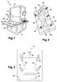
- the figure 1 schematically represents a device for setting The method of non-destructive testing of a fan blade woven preform proposed in the context of the invention, this device 10 comprising a frame 12 carrying a parallelepiped-shaped enclosure 14 and a movable plate 16 in a horizontal direction 18 between a first position where it is outside the enclosure 14 and a second position where it is inside the enclosure 14 ( figure 3 ).
- the movable plate 16 carries a support 20 on which the blade preform 22 is placed in a predetermined position.
- the enclosure 14 comprises a mobile panel 24 in translation in a direction 26 perpendicular to the horizontal direction 18 and revealing an opening through which the plate 16 is moved to come inside the enclosure 14 ( figure 1 ).
- the figure 2 represents the support 20 of the woven blade preform.
- the support comprises a plurality of bosses 28 dimensioned and distributed so as to position the preform in a predetermined position on the support 20.
- the bosses of the support prevent the blade preform 22 which has a certain flexibility from being deformed and thus make it possible to guarantee that the non-destructive inspection operation will be performed on a blade preform 22 shaped in three dimensions in a non-deformed state.
- the vane preform 22 comprises a plurality of first marker wires 30 intersecting with second marker wires 32 and woven with the preform wires on the extrados surface of the fan vane preform so as to form a grid.
- the first and second marker son 30, 32 have light reflection properties different from those of the son of the preform so as to make visible the grid of the first and second marker son relative to the son of the preform.
- the marker wires 30, 32 are white in color and the preform wires are black in color.
- the figure 3 represents the support 20 and the preform 22 inside the enclosure 14 in which image-taking means are housed comprising at least two image sensors 34, 36 mounted on a support 38 at a known distance from each other and whose axes 40, 42 form a known angle with each other.
- the blade preform 22 is arranged on its support 20 so that the two image sensors 30, 38 aim at the grid of the first and second marker wires 30, 32.
- the enclosure 14 also houses lighting means 44 of the grid of the blade preform 22.
- the enclosure 14 comprises opaque walls with light rays and absorbing light rays which could be reflected towards the walls by the support 20, the preform 22 or any other element inside the enclosure such as the sensors of In this way, it is possible to control the intensity of the light sent to the vane preform 22 and limit the reflections on the walls of the enclosure. Light from the outside is also limited.
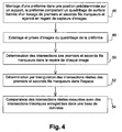
- a first step 46 an operator positions the preform on its support 20 in a known predetermined position opposite the image sensors 34, 36.
- a second step 48 the method then consists in illuminating the grid of the first and second marker wires 30, 32 of the preform with the lighting means and taking an image of this grid with each image sensor 34, 36.
- a third step 50 the method consists in determining the intersections of the first and second marker wires 30, 32 in the reference frame of each image. To this end, several mathematical treatments are applied to the images taken with the sensors 34, 36 and are described below with reference to Figures 5 to 13 .
- a work area 58 comprising the grid (FIG. figure 5 ). These markings on the image are obtained by means of light reflecting members formed on the support 20.
- a filter for suppressing the noise and low frequencies of the image is applied to each of the work areas 58 of each image so as to enhance the contrast of the visible portions of the first and second marker wires 30, 32 with respect to the bottom of the image. 'picture. This type of filtering by mathematical morphology is well known to those skilled in the art and does not require any particular description.
- the contours 57, 59 of the zones corresponding to the visible parts of the first and second marker wires are then determined by dynamic thresholding as a function of the shape and the level of reflection of the light of the visible parts 60, 62 relative to the rest of the picture ( figure 6 ).
- This type of thresholding known to those skilled in the art, consists in isolating the pixels of the image as a function of a given shape, of an outline and of a gray level with respect to the background of the image. picture. This type of filter also relies on the frequency of identification of the marker pixel pixels and their gray levels.
- the visible portions 60, 62 of the first and second son markers 30, 32 that is to say the parts located above the son of the preform have a generally elliptical shape and this information can thus be used as a discriminating parameter for the detection of the visible parts of the first and second son markers at the within each image.
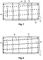
- the regions 64 of the image comprising visible portions of marker wires aligned according to the first marker threads 30 are then determined ( figure 7 ) and the zones 66 comprising visible parts aligned along the second marker wires 32 ( figure 8 ).
- a mathematical curve is determined such that a NURBS curve passing at best by the coordinates x i , y i corresponding to the center of the visible parts belonging to this region 64, 66.
- figure 9 represents the mathematical curves 70 obtained in the regions 64 oriented according to the first marker son 30 and the figure 10 represents the mathematical curves 72 obtained in the regions 66 oriented according to the second marker son 32.
- a smoothing of the mathematical curves 70, 72 is then performed ( Figures 11 and 12 ) to eliminate the aberrations of curvatures on the mathematical curves and the coordinates of the points of intersection 74 between the mathematical curves extending according to the first and second marker son 30, 32 are then determined ( figure 13 ).
- These intersections will be denoted 1 (x sensor1 , y sensor1 ) for a given intersection I in the reference of the image obtained with the first sensor 34 and I (x sensor2 , y sensor2 ) for the same intersection in the frame of the image obtained with the second sensor 36.
- the coordinates of all the points of intersection of the first and second marker wires 30, 32 are known in the reference frame of the image associated with the sensor 34, 36.
- the method consists in deducing the real coordinates X, Y and Z in the space of each intersection point I by a triangulation calculation using the coordinates of the point in the image obtained with the first sensor.
- a fifth step 54 the real positions of the intersection points of the first and second marker wires 30, 32 are compared with the three-dimensional theoretical positions of these same intersection points contained in a database, which makes it possible to deduce whether the preform 22 has been correctly woven or not.
- the third step 50 of the method is performed on n images with the first image sensor 34 and on n images obtained with the second image sensor 36.
- n images obtained with the second image sensor 36.
- a first set of n points x i torques, 1, yi, 1 corresponds to the point I of the grid coordinates in the coordinate system of the images obtained with the first sensor 34 and a second dot set of n pairs x i, 2, y i, 2 corresponds to the coordinates of the point I of the grid in the reference frame of the images obtained with the second sensor 36.
- the first threshold and the second threshold may be identical and for example equal to a value of 0.75 pixels. In a practical embodiment of the device, a pixel corresponds to about 0.2 mm.
- the number n of images is advantageously greater than or equal to 10.
- the lighting means 44 are light-emitting diodes whose luminous intensity is calibrated to optimize the contrast between the first and second marker wires 30, 32 and the wires of the preform.
- the image sensors 34, 36 are photodetector matrix cameras of the CCD or CMOS type having, for example, a resolution of 10 megapixels and a focal length of about 8.5 mm.
- the first and second marker son 30, 32 are for example made by an assembly of glass son and carbon son.
- the preform is for example made by weaving carbon son.
- the glass threads are lighter in color than the carbon threads.
- the method according to the invention can be used for non-destructive testing of any type of woven preform having a surface grid as previously described and is not limited to fan blade preforms. In particular, it could be used with preforms such as those used for the manufacture of casings or inter-blade platforms.
Landscapes
- Engineering & Computer Science (AREA)
- Quality & Reliability (AREA)
- Computer Vision & Pattern Recognition (AREA)
- Physics & Mathematics (AREA)
- General Physics & Mathematics (AREA)
- Theoretical Computer Science (AREA)
- Length Measuring Devices By Optical Means (AREA)
- Image Analysis (AREA)
- Analysing Materials By The Use Of Radiation (AREA)
Applications Claiming Priority (2)
| Application Number | Priority Date | Filing Date | Title |
|---|---|---|---|
| FR1257613A FR2994308B1 (fr) | 2012-08-03 | 2012-08-03 | Procede de controle non destructif d'une preforme d'aube |
| PCT/FR2013/051868 WO2014020288A1 (fr) | 2012-08-03 | 2013-08-01 | Procede de controle non destructif d'une preforme d'aube |
Publications (2)
| Publication Number | Publication Date |
|---|---|
| EP2880629A1 EP2880629A1 (fr) | 2015-06-10 |
| EP2880629B1 true EP2880629B1 (fr) | 2016-10-05 |
Family
ID=47553217
Family Applications (1)
| Application Number | Title | Priority Date | Filing Date |
|---|---|---|---|
| EP13756651.9A Active EP2880629B1 (fr) | 2012-08-03 | 2013-08-01 | Procede de controle non destructif d'une preforme d'aube |
Country Status (9)
| Country | Link |
|---|---|
| US (1) | US9530201B2 (ru) |
| EP (1) | EP2880629B1 (ru) |
| JP (1) | JP6227647B2 (ru) |
| CN (1) | CN104541303B (ru) |
| BR (1) | BR112015002238B1 (ru) |
| CA (1) | CA2880145C (ru) |
| FR (1) | FR2994308B1 (ru) |
| RU (1) | RU2632352C2 (ru) |
| WO (1) | WO2014020288A1 (ru) |
Families Citing this family (7)
| Publication number | Priority date | Publication date | Assignee | Title |
|---|---|---|---|---|
| CN104236879A (zh) * | 2014-08-25 | 2014-12-24 | 合肥工业大学 | 基于机器视觉的发动机叶片动静态检测方法 |
| FR3029134B1 (fr) * | 2014-12-02 | 2017-10-06 | Snecma | Procede de controle de position d'une preforme d'aube composite de turbomachine dans un moule |
| DE102015209257A1 (de) * | 2015-05-20 | 2016-11-24 | Lufthansa Technik Logistik Services Gmbh | Vorrichtung und Verfahren zur Remoteidentifikation von Luftfahrzeugmaterial |
| BR112018071410A8 (pt) * | 2016-04-22 | 2023-04-04 | The European Atomic Energy Community Euratom Represented By The European Commission | Sistema de vedação e seu método de instalação |
| US10774679B2 (en) | 2018-02-09 | 2020-09-15 | General Electric Company | Turbine engine airfoil assembly |
| FR3127042B1 (fr) * | 2021-09-15 | 2024-05-24 | Safran Aircraft Engines | Procédé de contrôle de pièces tissées de turbomachine |
| CN115605641B (zh) * | 2022-08-16 | 2024-06-28 | 远景能源有限公司 | 一种可进行缺陷检测的纤维织物及其风机叶片 |
Family Cites Families (9)
| Publication number | Priority date | Publication date | Assignee | Title |
|---|---|---|---|---|
| SU1739585A1 (ru) * | 1989-08-09 | 1994-01-15 | Всесоюзный институт легких сплавов | Способ получения дисков с лопатками |
| RU2047464C1 (ru) * | 1991-04-23 | 1995-11-10 | Гололобов Олег Александрович | Способ изготовления ротора лопаточной машины |
| FR2861143B1 (fr) * | 2003-10-20 | 2006-01-20 | Snecma Moteurs | Aube de turbomachine, notamment aube de soufflante et son procede de fabrication |
| FR2892339B1 (fr) * | 2005-10-21 | 2009-08-21 | Snecma Sa | Procede de fabrication d'une aube de turbomachine composite, et aube obtenue par ce procede |
| FR2913053B1 (fr) * | 2007-02-23 | 2009-05-22 | Snecma Sa | Procede de fabrication d'un carter de turbine a gaz en materiau composite et carter ainsi obtenu |
| FR2940449A1 (fr) * | 2008-12-24 | 2010-06-25 | Snecma | Procede de controle non destructif d'une piece mecanique |
| CN102135236B (zh) * | 2011-01-05 | 2013-05-01 | 北京航空航天大学 | 双目视觉管道内壁自动无损检测方法 |
| CN102231170B (zh) * | 2011-03-31 | 2013-12-04 | 西北工业大学 | 一种涡轮叶片模具型腔的参数化定型方法 |
| CN102779356B (zh) * | 2011-05-11 | 2016-01-06 | 鸿富锦精密工业(深圳)有限公司 | 曲面网格化系统及方法 |
-
2012
- 2012-08-03 FR FR1257613A patent/FR2994308B1/fr active Active
-
2013
- 2013-08-01 WO PCT/FR2013/051868 patent/WO2014020288A1/fr active Application Filing
- 2013-08-01 BR BR112015002238-3A patent/BR112015002238B1/pt active IP Right Grant
- 2013-08-01 CA CA2880145A patent/CA2880145C/fr active Active
- 2013-08-01 EP EP13756651.9A patent/EP2880629B1/fr active Active
- 2013-08-01 US US14/418,260 patent/US9530201B2/en active Active
- 2013-08-01 RU RU2015107204A patent/RU2632352C2/ru active
- 2013-08-01 JP JP2015524838A patent/JP6227647B2/ja active Active
- 2013-08-01 CN CN201380041214.7A patent/CN104541303B/zh active Active
Also Published As
| Publication number | Publication date |
|---|---|
| CA2880145A1 (fr) | 2014-02-06 |
| RU2015107204A (ru) | 2016-09-27 |
| WO2014020288A1 (fr) | 2014-02-06 |
| US20150302577A1 (en) | 2015-10-22 |
| CN104541303B (zh) | 2017-04-05 |
| RU2632352C2 (ru) | 2017-10-04 |
| US9530201B2 (en) | 2016-12-27 |
| EP2880629A1 (fr) | 2015-06-10 |
| FR2994308B1 (fr) | 2014-07-25 |
| FR2994308A1 (fr) | 2014-02-07 |
| CA2880145C (fr) | 2020-07-28 |
| JP2015526722A (ja) | 2015-09-10 |
| BR112015002238B1 (pt) | 2021-01-12 |
| JP6227647B2 (ja) | 2017-11-08 |
| CN104541303A (zh) | 2015-04-22 |
| BR112015002238A2 (pt) | 2017-07-04 |
Similar Documents
| Publication | Publication Date | Title |
|---|---|---|
| EP2880629B1 (fr) | Procede de controle non destructif d'une preforme d'aube | |
| CN109416245B (zh) | 用于测量表面形貌的设备和方法以及校准方法 | |
| CN104697998B (zh) | 抛光的宝石中的夹杂物检测 | |
| EP2225608B1 (fr) | Dispositif d'evaluation de la surface d'un pneumatique | |
| KR101150755B1 (ko) | 영상촬영장치 | |
| EP2646789B9 (fr) | Procédé de détermination d'au moins une caractéristique de réfraction d'une lentille ophtalmique | |
| BE1017316A7 (fr) | Appareil pour determiner le forme d'une gemme. | |
| FR2869408A1 (fr) | Procede et dispositif pour determiner la forme et les normales locales de surfaces reflechissantes | |
| FR2658286A1 (fr) | Appareil de determination de la configuration d'un corps monte rotatif sur un arbre et procede associe. | |
| FR2751067A1 (fr) | Systeme et sous-systeme de determination de l'attitude d'une camera a l'interieur d'un objet | |
| CN107727665A (zh) | 外观检查装置及外观检查方法 | |
| EP0662211B1 (fr) | Procede et ensemble de mesure pour mesurer les dimensions d'un objet | |
| CN108007382B (zh) | 基于结构光照明的面形测量装置和方法 | |
| FR3010182A1 (fr) | Methode et dispositif de determination de la position et de l'orientation d'une surface speculaire formant un dioptre | |
| EP3073441B1 (fr) | Procédé de correction d'une image d'au moins un objet présenté à distance devant un imageur et éclairé par un système d'éclairage et système de prise de vues pour la mise en oeuvre dudit procédé | |
| EP0756152B1 (fr) | Procédé et dispositif de détection de l'état de surface de pièces à surface réfléchissante, applicable au contrôle de rugosité de pièces polies | |
| CN108007387B (zh) | 基于结构光照明的面形测量装置和方法 | |
| FR2869983A1 (fr) | Procede de mesure de la position et/ou de l'orientation d'objets au moyen de procedes de traitement de l'image | |
| IL305183A (en) | A method for mapping the internal structure of a sample | |
| EP2637011A1 (fr) | Procédé et appareil de mesure de la structure géométrique d'un composant optique | |
| EP2742320B1 (fr) | Procede et appareil optoelectronique pour mesurer le diametre interne d'un corps creux | |
| RU69634U1 (ru) | Прибор для обнаружения и классификации дефектов оптических объектов (варианты) | |
| BE1015708A3 (fr) | Procede pour mesurer la hauteur de spheres ou d'hemispheres. | |
| JP2003329410A (ja) | 翼形部の前縁位置を光学測定する方法及び装置 | |
| WO2023141054A1 (en) | Surface analysis of gemstones |
Legal Events
| Date | Code | Title | Description |
|---|---|---|---|
| PUAI | Public reference made under article 153(3) epc to a published international application that has entered the european phase |
Free format text: ORIGINAL CODE: 0009012 |
|
| 17P | Request for examination filed |
Effective date: 20150203 |
|
| AK | Designated contracting states |
Kind code of ref document: A1 Designated state(s): AL AT BE BG CH CY CZ DE DK EE ES FI FR GB GR HR HU IE IS IT LI LT LU LV MC MK MT NL NO PL PT RO RS SE SI SK SM TR |
|
| AX | Request for extension of the european patent |
Extension state: BA ME |
|
| DAX | Request for extension of the european patent (deleted) | ||
| GRAP | Despatch of communication of intention to grant a patent |
Free format text: ORIGINAL CODE: EPIDOSNIGR1 |
|
| INTG | Intention to grant announced |
Effective date: 20160407 |
|
| GRAS | Grant fee paid |
Free format text: ORIGINAL CODE: EPIDOSNIGR3 |
|
| GRAA | (expected) grant |
Free format text: ORIGINAL CODE: 0009210 |
|
| AK | Designated contracting states |
Kind code of ref document: B1 Designated state(s): AL AT BE BG CH CY CZ DE DK EE ES FI FR GB GR HR HU IE IS IT LI LT LU LV MC MK MT NL NO PL PT RO RS SE SI SK SM TR |
|
| REG | Reference to a national code |
Ref country code: GB Ref legal event code: FG4D Free format text: NOT ENGLISH |
|
| REG | Reference to a national code |
Ref country code: CH Ref legal event code: EP |
|
| REG | Reference to a national code |
Ref country code: AT Ref legal event code: REF Ref document number: 835196 Country of ref document: AT Kind code of ref document: T Effective date: 20161015 |
|
| REG | Reference to a national code |
Ref country code: IE Ref legal event code: FG4D Free format text: LANGUAGE OF EP DOCUMENT: FRENCH |
|
| REG | Reference to a national code |
Ref country code: DE Ref legal event code: R096 Ref document number: 602013012479 Country of ref document: DE |
|
| REG | Reference to a national code |
Ref country code: SE Ref legal event code: TRGR |
|
| REG | Reference to a national code |
Ref country code: NL Ref legal event code: MP Effective date: 20161005 |
|
| REG | Reference to a national code |
Ref country code: LT Ref legal event code: MG4D |
|
| PG25 | Lapsed in a contracting state [announced via postgrant information from national office to epo] |
Ref country code: LV Free format text: LAPSE BECAUSE OF FAILURE TO SUBMIT A TRANSLATION OF THE DESCRIPTION OR TO PAY THE FEE WITHIN THE PRESCRIBED TIME-LIMIT Effective date: 20161005 |
|
| REG | Reference to a national code |
Ref country code: AT Ref legal event code: MK05 Ref document number: 835196 Country of ref document: AT Kind code of ref document: T Effective date: 20161005 |
|
| PG25 | Lapsed in a contracting state [announced via postgrant information from national office to epo] |
Ref country code: GR Free format text: LAPSE BECAUSE OF FAILURE TO SUBMIT A TRANSLATION OF THE DESCRIPTION OR TO PAY THE FEE WITHIN THE PRESCRIBED TIME-LIMIT Effective date: 20170106 Ref country code: LT Free format text: LAPSE BECAUSE OF FAILURE TO SUBMIT A TRANSLATION OF THE DESCRIPTION OR TO PAY THE FEE WITHIN THE PRESCRIBED TIME-LIMIT Effective date: 20161005 Ref country code: NO Free format text: LAPSE BECAUSE OF FAILURE TO SUBMIT A TRANSLATION OF THE DESCRIPTION OR TO PAY THE FEE WITHIN THE PRESCRIBED TIME-LIMIT Effective date: 20170105 |
|
| REG | Reference to a national code |
Ref country code: FR Ref legal event code: PLFP Year of fee payment: 5 |
|
| PG25 | Lapsed in a contracting state [announced via postgrant information from national office to epo] |
Ref country code: PL Free format text: LAPSE BECAUSE OF FAILURE TO SUBMIT A TRANSLATION OF THE DESCRIPTION OR TO PAY THE FEE WITHIN THE PRESCRIBED TIME-LIMIT Effective date: 20161005 Ref country code: RS Free format text: LAPSE BECAUSE OF FAILURE TO SUBMIT A TRANSLATION OF THE DESCRIPTION OR TO PAY THE FEE WITHIN THE PRESCRIBED TIME-LIMIT Effective date: 20161005 Ref country code: IS Free format text: LAPSE BECAUSE OF FAILURE TO SUBMIT A TRANSLATION OF THE DESCRIPTION OR TO PAY THE FEE WITHIN THE PRESCRIBED TIME-LIMIT Effective date: 20170205 Ref country code: PT Free format text: LAPSE BECAUSE OF FAILURE TO SUBMIT A TRANSLATION OF THE DESCRIPTION OR TO PAY THE FEE WITHIN THE PRESCRIBED TIME-LIMIT Effective date: 20170206 Ref country code: NL Free format text: LAPSE BECAUSE OF FAILURE TO SUBMIT A TRANSLATION OF THE DESCRIPTION OR TO PAY THE FEE WITHIN THE PRESCRIBED TIME-LIMIT Effective date: 20161005 Ref country code: HR Free format text: LAPSE BECAUSE OF FAILURE TO SUBMIT A TRANSLATION OF THE DESCRIPTION OR TO PAY THE FEE WITHIN THE PRESCRIBED TIME-LIMIT Effective date: 20161005 Ref country code: AT Free format text: LAPSE BECAUSE OF FAILURE TO SUBMIT A TRANSLATION OF THE DESCRIPTION OR TO PAY THE FEE WITHIN THE PRESCRIBED TIME-LIMIT Effective date: 20161005 Ref country code: ES Free format text: LAPSE BECAUSE OF FAILURE TO SUBMIT A TRANSLATION OF THE DESCRIPTION OR TO PAY THE FEE WITHIN THE PRESCRIBED TIME-LIMIT Effective date: 20161005 Ref country code: FI Free format text: LAPSE BECAUSE OF FAILURE TO SUBMIT A TRANSLATION OF THE DESCRIPTION OR TO PAY THE FEE WITHIN THE PRESCRIBED TIME-LIMIT Effective date: 20161005 |
|
| REG | Reference to a national code |
Ref country code: DE Ref legal event code: R097 Ref document number: 602013012479 Country of ref document: DE |
|
| PG25 | Lapsed in a contracting state [announced via postgrant information from national office to epo] |
Ref country code: CZ Free format text: LAPSE BECAUSE OF FAILURE TO SUBMIT A TRANSLATION OF THE DESCRIPTION OR TO PAY THE FEE WITHIN THE PRESCRIBED TIME-LIMIT Effective date: 20161005 Ref country code: RO Free format text: LAPSE BECAUSE OF FAILURE TO SUBMIT A TRANSLATION OF THE DESCRIPTION OR TO PAY THE FEE WITHIN THE PRESCRIBED TIME-LIMIT Effective date: 20161005 Ref country code: DK Free format text: LAPSE BECAUSE OF FAILURE TO SUBMIT A TRANSLATION OF THE DESCRIPTION OR TO PAY THE FEE WITHIN THE PRESCRIBED TIME-LIMIT Effective date: 20161005 Ref country code: EE Free format text: LAPSE BECAUSE OF FAILURE TO SUBMIT A TRANSLATION OF THE DESCRIPTION OR TO PAY THE FEE WITHIN THE PRESCRIBED TIME-LIMIT Effective date: 20161005 Ref country code: SK Free format text: LAPSE BECAUSE OF FAILURE TO SUBMIT A TRANSLATION OF THE DESCRIPTION OR TO PAY THE FEE WITHIN THE PRESCRIBED TIME-LIMIT Effective date: 20161005 |
|
| PLBE | No opposition filed within time limit |
Free format text: ORIGINAL CODE: 0009261 |
|
| STAA | Information on the status of an ep patent application or granted ep patent |
Free format text: STATUS: NO OPPOSITION FILED WITHIN TIME LIMIT |
|
| PG25 | Lapsed in a contracting state [announced via postgrant information from national office to epo] |
Ref country code: BG Free format text: LAPSE BECAUSE OF FAILURE TO SUBMIT A TRANSLATION OF THE DESCRIPTION OR TO PAY THE FEE WITHIN THE PRESCRIBED TIME-LIMIT Effective date: 20170105 Ref country code: SM Free format text: LAPSE BECAUSE OF FAILURE TO SUBMIT A TRANSLATION OF THE DESCRIPTION OR TO PAY THE FEE WITHIN THE PRESCRIBED TIME-LIMIT Effective date: 20161005 |
|
| 26N | No opposition filed |
Effective date: 20170706 |
|
| PG25 | Lapsed in a contracting state [announced via postgrant information from national office to epo] |
Ref country code: SI Free format text: LAPSE BECAUSE OF FAILURE TO SUBMIT A TRANSLATION OF THE DESCRIPTION OR TO PAY THE FEE WITHIN THE PRESCRIBED TIME-LIMIT Effective date: 20161005 |
|
| REG | Reference to a national code |
Ref country code: CH Ref legal event code: PL |
|
| PG25 | Lapsed in a contracting state [announced via postgrant information from national office to epo] |
Ref country code: MC Free format text: LAPSE BECAUSE OF FAILURE TO SUBMIT A TRANSLATION OF THE DESCRIPTION OR TO PAY THE FEE WITHIN THE PRESCRIBED TIME-LIMIT Effective date: 20161005 |
|
| PG25 | Lapsed in a contracting state [announced via postgrant information from national office to epo] |
Ref country code: LI Free format text: LAPSE BECAUSE OF NON-PAYMENT OF DUE FEES Effective date: 20170831 Ref country code: CH Free format text: LAPSE BECAUSE OF NON-PAYMENT OF DUE FEES Effective date: 20170831 |
|
| REG | Reference to a national code |
Ref country code: IE Ref legal event code: MM4A |
|
| REG | Reference to a national code |
Ref country code: BE Ref legal event code: MM Effective date: 20170831 |
|
| PG25 | Lapsed in a contracting state [announced via postgrant information from national office to epo] |
Ref country code: LU Free format text: LAPSE BECAUSE OF NON-PAYMENT OF DUE FEES Effective date: 20170801 |
|
| REG | Reference to a national code |
Ref country code: FR Ref legal event code: PLFP Year of fee payment: 6 |
|
| PG25 | Lapsed in a contracting state [announced via postgrant information from national office to epo] |
Ref country code: IE Free format text: LAPSE BECAUSE OF NON-PAYMENT OF DUE FEES Effective date: 20170801 |
|
| PG25 | Lapsed in a contracting state [announced via postgrant information from national office to epo] |
Ref country code: BE Free format text: LAPSE BECAUSE OF NON-PAYMENT OF DUE FEES Effective date: 20170831 |
|
| PG25 | Lapsed in a contracting state [announced via postgrant information from national office to epo] |
Ref country code: MT Free format text: LAPSE BECAUSE OF FAILURE TO SUBMIT A TRANSLATION OF THE DESCRIPTION OR TO PAY THE FEE WITHIN THE PRESCRIBED TIME-LIMIT Effective date: 20161005 |
|
| PG25 | Lapsed in a contracting state [announced via postgrant information from national office to epo] |
Ref country code: HU Free format text: LAPSE BECAUSE OF FAILURE TO SUBMIT A TRANSLATION OF THE DESCRIPTION OR TO PAY THE FEE WITHIN THE PRESCRIBED TIME-LIMIT; INVALID AB INITIO Effective date: 20130801 |
|
| PG25 | Lapsed in a contracting state [announced via postgrant information from national office to epo] |
Ref country code: CY Free format text: LAPSE BECAUSE OF FAILURE TO SUBMIT A TRANSLATION OF THE DESCRIPTION OR TO PAY THE FEE WITHIN THE PRESCRIBED TIME-LIMIT Effective date: 20161005 |
|
| PG25 | Lapsed in a contracting state [announced via postgrant information from national office to epo] |
Ref country code: MK Free format text: LAPSE BECAUSE OF FAILURE TO SUBMIT A TRANSLATION OF THE DESCRIPTION OR TO PAY THE FEE WITHIN THE PRESCRIBED TIME-LIMIT Effective date: 20161005 |
|
| PG25 | Lapsed in a contracting state [announced via postgrant information from national office to epo] |
Ref country code: TR Free format text: LAPSE BECAUSE OF FAILURE TO SUBMIT A TRANSLATION OF THE DESCRIPTION OR TO PAY THE FEE WITHIN THE PRESCRIBED TIME-LIMIT Effective date: 20161005 |
|
| PG25 | Lapsed in a contracting state [announced via postgrant information from national office to epo] |
Ref country code: AL Free format text: LAPSE BECAUSE OF FAILURE TO SUBMIT A TRANSLATION OF THE DESCRIPTION OR TO PAY THE FEE WITHIN THE PRESCRIBED TIME-LIMIT Effective date: 20161005 |
|
| PGFP | Annual fee paid to national office [announced via postgrant information from national office to epo] |
Ref country code: IT Payment date: 20230720 Year of fee payment: 11 |
|
| PGFP | Annual fee paid to national office [announced via postgrant information from national office to epo] |
Ref country code: SE Payment date: 20230720 Year of fee payment: 11 |
|
| PGFP | Annual fee paid to national office [announced via postgrant information from national office to epo] |
Ref country code: DE Payment date: 20240723 Year of fee payment: 12 |
|
| PGFP | Annual fee paid to national office [announced via postgrant information from national office to epo] |
Ref country code: GB Payment date: 20240723 Year of fee payment: 12 |
|
| PGFP | Annual fee paid to national office [announced via postgrant information from national office to epo] |
Ref country code: FR Payment date: 20240723 Year of fee payment: 12 |