EP2880322B1 - Control method, program and system for controlling the bearing preload of a wind turbine and wind turbine comprising such control system - Google Patents
Control method, program and system for controlling the bearing preload of a wind turbine and wind turbine comprising such control system Download PDFInfo
- Publication number
- EP2880322B1 EP2880322B1 EP13777137.4A EP13777137A EP2880322B1 EP 2880322 B1 EP2880322 B1 EP 2880322B1 EP 13777137 A EP13777137 A EP 13777137A EP 2880322 B1 EP2880322 B1 EP 2880322B1
- Authority
- EP
- European Patent Office
- Prior art keywords
- preload
- bearing
- inner ring
- outer ring
- temperature
- Prior art date
- Legal status (The legal status is an assumption and is not a legal conclusion. Google has not performed a legal analysis and makes no representation as to the accuracy of the status listed.)
- Active
Links
Images



Classifications
-
- F—MECHANICAL ENGINEERING; LIGHTING; HEATING; WEAPONS; BLASTING
- F03—MACHINES OR ENGINES FOR LIQUIDS; WIND, SPRING, OR WEIGHT MOTORS; PRODUCING MECHANICAL POWER OR A REACTIVE PROPULSIVE THRUST, NOT OTHERWISE PROVIDED FOR
- F03D—WIND MOTORS
- F03D7/00—Controlling wind motors
-
- F—MECHANICAL ENGINEERING; LIGHTING; HEATING; WEAPONS; BLASTING
- F16—ENGINEERING ELEMENTS AND UNITS; GENERAL MEASURES FOR PRODUCING AND MAINTAINING EFFECTIVE FUNCTIONING OF MACHINES OR INSTALLATIONS; THERMAL INSULATION IN GENERAL
- F16C—SHAFTS; FLEXIBLE SHAFTS; ELEMENTS OR CRANKSHAFT MECHANISMS; ROTARY BODIES OTHER THAN GEARING ELEMENTS; BEARINGS
- F16C19/00—Bearings with rolling contact, for exclusively rotary movement
- F16C19/52—Bearings with rolling contact, for exclusively rotary movement with devices affected by abnormal or undesired conditions
- F16C19/525—Bearings with rolling contact, for exclusively rotary movement with devices affected by abnormal or undesired conditions related to temperature and heat, e.g. insulation
-
- F—MECHANICAL ENGINEERING; LIGHTING; HEATING; WEAPONS; BLASTING
- F03—MACHINES OR ENGINES FOR LIQUIDS; WIND, SPRING, OR WEIGHT MOTORS; PRODUCING MECHANICAL POWER OR A REACTIVE PROPULSIVE THRUST, NOT OTHERWISE PROVIDED FOR
- F03D—WIND MOTORS
- F03D7/00—Controlling wind motors
- F03D7/02—Controlling wind motors the wind motors having rotation axis substantially parallel to the air flow entering the rotor
- F03D7/04—Automatic control; Regulation
- F03D7/042—Automatic control; Regulation by means of an electrical or electronic controller
-
- F—MECHANICAL ENGINEERING; LIGHTING; HEATING; WEAPONS; BLASTING
- F03—MACHINES OR ENGINES FOR LIQUIDS; WIND, SPRING, OR WEIGHT MOTORS; PRODUCING MECHANICAL POWER OR A REACTIVE PROPULSIVE THRUST, NOT OTHERWISE PROVIDED FOR
- F03D—WIND MOTORS
- F03D80/00—Details, components or accessories not provided for in groups F03D1/00 - F03D17/00
- F03D80/60—Cooling or heating of wind motors
-
- F—MECHANICAL ENGINEERING; LIGHTING; HEATING; WEAPONS; BLASTING
- F03—MACHINES OR ENGINES FOR LIQUIDS; WIND, SPRING, OR WEIGHT MOTORS; PRODUCING MECHANICAL POWER OR A REACTIVE PROPULSIVE THRUST, NOT OTHERWISE PROVIDED FOR
- F03D—WIND MOTORS
- F03D80/00—Details, components or accessories not provided for in groups F03D1/00 - F03D17/00
- F03D80/70—Bearing or lubricating arrangements
-
- F—MECHANICAL ENGINEERING; LIGHTING; HEATING; WEAPONS; BLASTING
- F03—MACHINES OR ENGINES FOR LIQUIDS; WIND, SPRING, OR WEIGHT MOTORS; PRODUCING MECHANICAL POWER OR A REACTIVE PROPULSIVE THRUST, NOT OTHERWISE PROVIDED FOR
- F03D—WIND MOTORS
- F03D9/00—Adaptations of wind motors for special use; Combinations of wind motors with apparatus driven thereby; Wind motors specially adapted for installation in particular locations
- F03D9/20—Wind motors characterised by the driven apparatus
- F03D9/25—Wind motors characterised by the driven apparatus the apparatus being an electrical generator
-
- F—MECHANICAL ENGINEERING; LIGHTING; HEATING; WEAPONS; BLASTING
- F16—ENGINEERING ELEMENTS AND UNITS; GENERAL MEASURES FOR PRODUCING AND MAINTAINING EFFECTIVE FUNCTIONING OF MACHINES OR INSTALLATIONS; THERMAL INSULATION IN GENERAL
- F16C—SHAFTS; FLEXIBLE SHAFTS; ELEMENTS OR CRANKSHAFT MECHANISMS; ROTARY BODIES OTHER THAN GEARING ELEMENTS; BEARINGS
- F16C19/00—Bearings with rolling contact, for exclusively rotary movement
- F16C19/02—Bearings with rolling contact, for exclusively rotary movement with bearing balls essentially of the same size in one or more circular rows
- F16C19/14—Bearings with rolling contact, for exclusively rotary movement with bearing balls essentially of the same size in one or more circular rows for both radial and axial load
- F16C19/18—Bearings with rolling contact, for exclusively rotary movement with bearing balls essentially of the same size in one or more circular rows for both radial and axial load with two or more rows of balls
- F16C19/181—Bearings with rolling contact, for exclusively rotary movement with bearing balls essentially of the same size in one or more circular rows for both radial and axial load with two or more rows of balls with angular contact
- F16C19/183—Bearings with rolling contact, for exclusively rotary movement with bearing balls essentially of the same size in one or more circular rows for both radial and axial load with two or more rows of balls with angular contact with two rows at opposite angles
- F16C19/184—Bearings with rolling contact, for exclusively rotary movement with bearing balls essentially of the same size in one or more circular rows for both radial and axial load with two or more rows of balls with angular contact with two rows at opposite angles in O-arrangement
-
- F—MECHANICAL ENGINEERING; LIGHTING; HEATING; WEAPONS; BLASTING
- F16—ENGINEERING ELEMENTS AND UNITS; GENERAL MEASURES FOR PRODUCING AND MAINTAINING EFFECTIVE FUNCTIONING OF MACHINES OR INSTALLATIONS; THERMAL INSULATION IN GENERAL
- F16C—SHAFTS; FLEXIBLE SHAFTS; ELEMENTS OR CRANKSHAFT MECHANISMS; ROTARY BODIES OTHER THAN GEARING ELEMENTS; BEARINGS
- F16C19/00—Bearings with rolling contact, for exclusively rotary movement
- F16C19/22—Bearings with rolling contact, for exclusively rotary movement with bearing rollers essentially of the same size in one or more circular rows, e.g. needle bearings
- F16C19/34—Bearings with rolling contact, for exclusively rotary movement with bearing rollers essentially of the same size in one or more circular rows, e.g. needle bearings for both radial and axial load
- F16C19/38—Bearings with rolling contact, for exclusively rotary movement with bearing rollers essentially of the same size in one or more circular rows, e.g. needle bearings for both radial and axial load with two or more rows of rollers
- F16C19/383—Bearings with rolling contact, for exclusively rotary movement with bearing rollers essentially of the same size in one or more circular rows, e.g. needle bearings for both radial and axial load with two or more rows of rollers with tapered rollers, i.e. rollers having essentially the shape of a truncated cone
- F16C19/385—Bearings with rolling contact, for exclusively rotary movement with bearing rollers essentially of the same size in one or more circular rows, e.g. needle bearings for both radial and axial load with two or more rows of rollers with tapered rollers, i.e. rollers having essentially the shape of a truncated cone with two rows, i.e. double-row tapered roller bearings
- F16C19/386—Bearings with rolling contact, for exclusively rotary movement with bearing rollers essentially of the same size in one or more circular rows, e.g. needle bearings for both radial and axial load with two or more rows of rollers with tapered rollers, i.e. rollers having essentially the shape of a truncated cone with two rows, i.e. double-row tapered roller bearings in O-arrangement
-
- F—MECHANICAL ENGINEERING; LIGHTING; HEATING; WEAPONS; BLASTING
- F16—ENGINEERING ELEMENTS AND UNITS; GENERAL MEASURES FOR PRODUCING AND MAINTAINING EFFECTIVE FUNCTIONING OF MACHINES OR INSTALLATIONS; THERMAL INSULATION IN GENERAL
- F16C—SHAFTS; FLEXIBLE SHAFTS; ELEMENTS OR CRANKSHAFT MECHANISMS; ROTARY BODIES OTHER THAN GEARING ELEMENTS; BEARINGS
- F16C19/00—Bearings with rolling contact, for exclusively rotary movement
- F16C19/54—Systems consisting of a plurality of bearings with rolling friction
- F16C19/546—Systems with spaced apart rolling bearings including at least one angular contact bearing
- F16C19/547—Systems with spaced apart rolling bearings including at least one angular contact bearing with two angular contact rolling bearings
-
- F—MECHANICAL ENGINEERING; LIGHTING; HEATING; WEAPONS; BLASTING
- F16—ENGINEERING ELEMENTS AND UNITS; GENERAL MEASURES FOR PRODUCING AND MAINTAINING EFFECTIVE FUNCTIONING OF MACHINES OR INSTALLATIONS; THERMAL INSULATION IN GENERAL
- F16C—SHAFTS; FLEXIBLE SHAFTS; ELEMENTS OR CRANKSHAFT MECHANISMS; ROTARY BODIES OTHER THAN GEARING ELEMENTS; BEARINGS
- F16C25/00—Bearings for exclusively rotary movement adjustable for wear or play
- F16C25/06—Ball or roller bearings
- F16C25/08—Ball or roller bearings self-adjusting
-
- F—MECHANICAL ENGINEERING; LIGHTING; HEATING; WEAPONS; BLASTING
- F16—ENGINEERING ELEMENTS AND UNITS; GENERAL MEASURES FOR PRODUCING AND MAINTAINING EFFECTIVE FUNCTIONING OF MACHINES OR INSTALLATIONS; THERMAL INSULATION IN GENERAL
- F16C—SHAFTS; FLEXIBLE SHAFTS; ELEMENTS OR CRANKSHAFT MECHANISMS; ROTARY BODIES OTHER THAN GEARING ELEMENTS; BEARINGS
- F16C37/00—Cooling of bearings
- F16C37/007—Cooling of bearings of rolling bearings
-
- F—MECHANICAL ENGINEERING; LIGHTING; HEATING; WEAPONS; BLASTING
- F16—ENGINEERING ELEMENTS AND UNITS; GENERAL MEASURES FOR PRODUCING AND MAINTAINING EFFECTIVE FUNCTIONING OF MACHINES OR INSTALLATIONS; THERMAL INSULATION IN GENERAL
- F16C—SHAFTS; FLEXIBLE SHAFTS; ELEMENTS OR CRANKSHAFT MECHANISMS; ROTARY BODIES OTHER THAN GEARING ELEMENTS; BEARINGS
- F16C19/00—Bearings with rolling contact, for exclusively rotary movement
- F16C19/02—Bearings with rolling contact, for exclusively rotary movement with bearing balls essentially of the same size in one or more circular rows
- F16C19/14—Bearings with rolling contact, for exclusively rotary movement with bearing balls essentially of the same size in one or more circular rows for both radial and axial load
- F16C19/16—Bearings with rolling contact, for exclusively rotary movement with bearing balls essentially of the same size in one or more circular rows for both radial and axial load with a single row of balls
- F16C19/163—Bearings with rolling contact, for exclusively rotary movement with bearing balls essentially of the same size in one or more circular rows for both radial and axial load with a single row of balls with angular contact
-
- F—MECHANICAL ENGINEERING; LIGHTING; HEATING; WEAPONS; BLASTING
- F16—ENGINEERING ELEMENTS AND UNITS; GENERAL MEASURES FOR PRODUCING AND MAINTAINING EFFECTIVE FUNCTIONING OF MACHINES OR INSTALLATIONS; THERMAL INSULATION IN GENERAL
- F16C—SHAFTS; FLEXIBLE SHAFTS; ELEMENTS OR CRANKSHAFT MECHANISMS; ROTARY BODIES OTHER THAN GEARING ELEMENTS; BEARINGS
- F16C2226/00—Joining parts; Fastening; Assembling or mounting parts
- F16C2226/50—Positive connections
- F16C2226/60—Positive connections with threaded parts, e.g. bolt and nut connections
-
- F—MECHANICAL ENGINEERING; LIGHTING; HEATING; WEAPONS; BLASTING
- F16—ENGINEERING ELEMENTS AND UNITS; GENERAL MEASURES FOR PRODUCING AND MAINTAINING EFFECTIVE FUNCTIONING OF MACHINES OR INSTALLATIONS; THERMAL INSULATION IN GENERAL
- F16C—SHAFTS; FLEXIBLE SHAFTS; ELEMENTS OR CRANKSHAFT MECHANISMS; ROTARY BODIES OTHER THAN GEARING ELEMENTS; BEARINGS
- F16C2229/00—Setting preload
-
- F—MECHANICAL ENGINEERING; LIGHTING; HEATING; WEAPONS; BLASTING
- F16—ENGINEERING ELEMENTS AND UNITS; GENERAL MEASURES FOR PRODUCING AND MAINTAINING EFFECTIVE FUNCTIONING OF MACHINES OR INSTALLATIONS; THERMAL INSULATION IN GENERAL
- F16C—SHAFTS; FLEXIBLE SHAFTS; ELEMENTS OR CRANKSHAFT MECHANISMS; ROTARY BODIES OTHER THAN GEARING ELEMENTS; BEARINGS
- F16C2233/00—Monitoring condition, e.g. temperature, load, vibration
-
- F—MECHANICAL ENGINEERING; LIGHTING; HEATING; WEAPONS; BLASTING
- F16—ENGINEERING ELEMENTS AND UNITS; GENERAL MEASURES FOR PRODUCING AND MAINTAINING EFFECTIVE FUNCTIONING OF MACHINES OR INSTALLATIONS; THERMAL INSULATION IN GENERAL
- F16C—SHAFTS; FLEXIBLE SHAFTS; ELEMENTS OR CRANKSHAFT MECHANISMS; ROTARY BODIES OTHER THAN GEARING ELEMENTS; BEARINGS
- F16C2300/00—Application independent of particular apparatuses
- F16C2300/10—Application independent of particular apparatuses related to size
- F16C2300/14—Large applications, e.g. bearings having an inner diameter exceeding 500 mm
-
- F—MECHANICAL ENGINEERING; LIGHTING; HEATING; WEAPONS; BLASTING
- F16—ENGINEERING ELEMENTS AND UNITS; GENERAL MEASURES FOR PRODUCING AND MAINTAINING EFFECTIVE FUNCTIONING OF MACHINES OR INSTALLATIONS; THERMAL INSULATION IN GENERAL
- F16C—SHAFTS; FLEXIBLE SHAFTS; ELEMENTS OR CRANKSHAFT MECHANISMS; ROTARY BODIES OTHER THAN GEARING ELEMENTS; BEARINGS
- F16C2300/00—Application independent of particular apparatuses
- F16C2300/40—Application independent of particular apparatuses related to environment, i.e. operating conditions
-
- F—MECHANICAL ENGINEERING; LIGHTING; HEATING; WEAPONS; BLASTING
- F16—ENGINEERING ELEMENTS AND UNITS; GENERAL MEASURES FOR PRODUCING AND MAINTAINING EFFECTIVE FUNCTIONING OF MACHINES OR INSTALLATIONS; THERMAL INSULATION IN GENERAL
- F16C—SHAFTS; FLEXIBLE SHAFTS; ELEMENTS OR CRANKSHAFT MECHANISMS; ROTARY BODIES OTHER THAN GEARING ELEMENTS; BEARINGS
- F16C2360/00—Engines or pumps
- F16C2360/31—Wind motors
-
- F—MECHANICAL ENGINEERING; LIGHTING; HEATING; WEAPONS; BLASTING
- F16—ENGINEERING ELEMENTS AND UNITS; GENERAL MEASURES FOR PRODUCING AND MAINTAINING EFFECTIVE FUNCTIONING OF MACHINES OR INSTALLATIONS; THERMAL INSULATION IN GENERAL
- F16C—SHAFTS; FLEXIBLE SHAFTS; ELEMENTS OR CRANKSHAFT MECHANISMS; ROTARY BODIES OTHER THAN GEARING ELEMENTS; BEARINGS
- F16C33/00—Parts of bearings; Special methods for making bearings or parts thereof
- F16C33/30—Parts of ball or roller bearings
- F16C33/58—Raceways; Race rings
- F16C33/583—Details of specific parts of races
- F16C33/586—Details of specific parts of races outside the space between the races, e.g. end faces or bore of inner ring
-
- Y—GENERAL TAGGING OF NEW TECHNOLOGICAL DEVELOPMENTS; GENERAL TAGGING OF CROSS-SECTIONAL TECHNOLOGIES SPANNING OVER SEVERAL SECTIONS OF THE IPC; TECHNICAL SUBJECTS COVERED BY FORMER USPC CROSS-REFERENCE ART COLLECTIONS [XRACs] AND DIGESTS
- Y02—TECHNOLOGIES OR APPLICATIONS FOR MITIGATION OR ADAPTATION AGAINST CLIMATE CHANGE
- Y02E—REDUCTION OF GREENHOUSE GAS [GHG] EMISSIONS, RELATED TO ENERGY GENERATION, TRANSMISSION OR DISTRIBUTION
- Y02E10/00—Energy generation through renewable energy sources
- Y02E10/70—Wind energy
- Y02E10/72—Wind turbines with rotation axis in wind direction
Definitions
- the present invention relates to a method of controlling the preload of a wind turbine bearing.
- a wind turbine for producing electric energy normally comprises a main frame that rotates about a vertical axis; a blade assembly, which comprises a hub fitted with at least two blades, and is connected to the main frame by at least one bearing to permit rotation of the blade assembly about an axis of rotation; and a rotary electric machine, which is rotated by the blade assembly, and comprises a stator connected to the main frame., and a rotor connected to the blade assembly.
- the stator comprises a tubular first active part
- the rotor comprises a tubular second active part facing, and separated by an air gap from, the tubular first active part.
- the efficiency of a rotary electric machine is known to be affected significantly by the size of the air gap : the smaller the air gap, the greater the efficiency of the electric machine.
- the blade assembly On direct-drive wind turbines, the blade assembly is connected rigidly to the rotor, and the bearding serves to support both the rotor and the blade assembly for rotation about the axis of rotation; and a fairly common practice is to employ one bearing designed to absorb radial and axial forces and tipping moments. Other wind turbine configurations employ two coaxial bearings.
- the bearings used between the blade assembly and main frame of wind turbines are normally rolling bearings.
- a rolling bearing comprises an outer ring and an inner ring; and at least one ring of rolling bodies equally spaced about the axis of rotation; between the outer and inner rings.
- the bearing can be assembled to achieve a small amount of both radial and axial interference.
- Rolling bearings may normally be assembled with interference or clearance; and in the following description, the term 'preload' is used to describe both interference and clearance configurations.
- the set preload on the bearing at the installation stage may vary widely over time, depending on the temperature range at the wind turbine installation site, and on operating conditions, such as the heat generated by the rotary electric machine, friction in the bearing, and the efficiency of the cooling system. Changes in the preload of the bearing may produce severe stress on the bearing, wear affecting the working life of the bearing, or slack which equally impairs the working life of the bearing and also alters the size of the air gap. Changes in the preload of the bearing therefore have a particularly harmful effect on the working life of the bearing and, in some situations, also on the efficiency of the electric machine.
- Document EP 2,290,250 discloses a method for controlling the temperature of a sleeve supporting two bearing at its opposite ends for a cartridge of drive-train of a geared wind turbine.
- a control method for controlling the preload of a wind turbine bearing comprising the steps of estimating the preload on the bearing at least as a function of the temperature of the outer ring and the inner ring; comparing the estimated preload with a predetermined acceptance range; and correcting the preload on the bearing when the preload is outside the acceptance range; detecting the temperature of the outer ring; detecting the temperature of the inner ring; calculating the temperature difference between the outer ring and the inner ring; controlling the temperature of the outer ring and the inner ring as a function of the temperature difference between the outer ring and the inner ring so as to keep the preload within the predetermined acceptance range.
- the step of estimating the preload comprises calculating the preload on the basis of the structural, dimensional, and assembly characteristics, and the temperature of the bearing.
- the step of correcting the preload on the bearing comprises directly or indirectly heating or cooling the outer ring and/or inner ring.
- control method comprises determining the temperature of the outer ring and the inner ring, or of the supporting structures close to them. In this way, it is possible to implement a closed-cycle control algorithm.
- the temperature of the outer ring and the inner ring is preferably closed-cycle controlled by determining the temperature of the outer ring and the inner ring, or the temperature close to them, but open-cycle controls are not excluded.
- the present invention also relates to a program for controlling the preload of a bearing.
- a computer program loadable directly into a memory of a control unit to perform the steps in the method according to the present invention when the program is implemented by the control unit.
- the program may also be stored in a mobile memory on a readable medium on which the program is stored.
- the present invention also relates to a control system for controlling the preload of a wind turbine bearing.
- a control system for controlling the preload of a wind turbine bearing, the control system comprising a control unit configured to estimate the preload on the bearing at least as a function of the temperature of the outer ring and the inner ring; compare the estimated preload with a predetermined acceptance range; and correct the preload on the bearing when the preload is outside the acceptance range; at least one first sensor for detecting the temperature of the outer ring; at least one second sensor for detecting the temperature of the inner ring, wherein the control unit is configured to calculate the temperature difference between the outer ring and the inner ring and to control a first and a second control device to adjust the temperature of the outer ring and the inner ring respectively as a function of the temperature difference between the outer ring and the inner ring so as to keep the preload within the predetermined acceptance range.
- control system provides for optimizing the working life of the bearing and the efficiency of the wind turbine electric machine cheaply and easily.
- control unit is configured to calculate the preload on the basis of the structural, dimensional, and assembly characteristics, and the temperature of the bearing.
- the control unit is preferably programmable, has a memory in which to store bearing data, is designed to receive outside information, such as the detected temperatures of the outer ring and inner ring, and is designed to emit control signals to control a first and second control device.
- the control unit is also designed to emit alarm signals in the event of anomalous operating situations with respect to recorded history data.
- the present invention also relates to a wind turbine.
- a wind turbine for producing electric energy, the wind turbine comprising a blade assembly rotatable about an axis of rotation; a rotary electric machine comprising a stator, and a rotor connected to the blade assembly; a bearing for supporting the blade assembly about the axis of rotation; and a control system configured to control the preload of the bearing and in accordance with the present invention.
- the above configuration provides for achieving a small air gap, and improving the efficiency, of the rotary electric machine.
- Wind turbine 1 indicates as a whole a wind turbine for producing electric energy.
- Wind turbine 1 is a direct-drive type.
- wind turbine 1 comprises a main frame 2; a rotary electric machine 3; and a blade assembly 4 which rotates about an axis of rotation A.
- Rotary electric machine 3 is located between main frame 2 and blade assembly 4 and, in addition to producing electric energy, serves, to support blade assembly 4 and to transmit forces and moments induced by blade assembly 4 and rotary electric machine 3 itself to main frame 2.
- main frame 2 is defiried by a curved, tubular nacelle 5 comprising a circular end flange 6 for connection to rotary electric machine 3; an end flange 7 for housing a pivot (not shown) for connection to a vertical support (not shown); and an opening 8 in the wall of nacelle 5, through which to insert and remove large component parts.
- opening 8 is substantially aligned with end flange 6.
- Blade assembly 4 comprises a hub 9 connected to rotary electric machine 3; and a plurality of blades (not shown in the drawings).
- Hub 9 comprises a hollow member 10 for supporting the blades (not shown); and a flange 11 for connection to rotary electric machine 3.
- Rotary electric machine 3 extends about axis of rotation A, and is substantially tubular, so as to form a passage between the hollow main frame 2 and hollow hub 9.
- Rotary electric machine 3 comprises a stator 12; a rotor 13 located inside stator 12 and which rotates with respect to stator 12 about axis of rotation A.
- Rotary electric machine 3 comprises a frame 14 for connecting rotary electric machine 3 to main frame 2, and for supporting blade assembly 4, stator 12, and rotor 13.
- Frame 14 extends about axis of rotation A, and comprises a tubular structure 15, which has a cylindrical face 16 and is designed to support a tubular active part 17 along cylindrical face 16; an annular flange 18 for connecting rotary electric machine 3 to main frame 2 of wind turbine 1; and a ring 19 having an annular seat 20 for at least partly housing a bearing 21.
- one bearing 21 supports blade assembly 4 and rotor 13 integral with blade assembly 4.
- frame 14 forms part of tubular stator 12, since tubular structure 15 forms part of tubular stator 12.
- tubular stator 12 comprises tubular structure 15 and active part 17.
- Tubular active part 17 is divided into a plurality of axial active segments 22, each of which, in the example shown, has electric windings fitted to a ferromagnetic, substantially prismatic core extending predominantly parallel to axis of rotation A.
- Tubular structure 15 is cylindrical and extends about axis of rotation A.
- Annular flange 18 is coaxial with tubular structure 15 and smaller in diameter than cylindrical face 16.
- ring 19 is coaxial with tubular structure 15 and smaller in diameter than annular flange 18.
- Annular flange 18 is located inside the end of tubular structure 15, along axis of rotation A.
- Ring 19 is located inside the central area of tubular structure 15, along axis of rotation A.
- Tubular structure 15, annular flange 18 and ring 19 are connected rigidly to one another by arms 23 and 24. More specifically, tubular structure 15 is connected to annular flange 18 by arms 23, which extend predominantly radially with a small axial component; and annular flange 18 is connected to ring 19 by arms 24, which extend predominantly axially with a small radial component.
- Each arm 23 comprises two plates 25 parallel to each other and to axis of rotation A.
- each arm 24 comprises two plates 26 also parallel to each other and to axis of rotation A.
- Annular flange 18 has a seat 27 for connection to main frame 2 of wind turbine 1.
- Frame 14 and main frame 2 are preferably connected by a bolted joint (not shown in the drawings) between annular flange 18 and end flange 6, and by which the forces and moments induced by rotary electric machine 3 and blade assembly 4 are transmitted to main frame 2.
- Rotary electric machine 3 i.e. wind turbine 1 preferably has only bearing 21 to withstand the radial and axial loads transmitted from tubular rotor 13 and blade assembly 4 to main frame 2.
- bearing 21 is a rolling bearing, comprises an outer ring 28 and an inner ring 29, and is housed in annular seat 20 of ring 19. More specifically, outer ring 28 is housed in annular seat 20, and inner ring 29 is connected to tubular rotor 13. Annular seat 20 has a step profile, with cylindrical faces alternating with annular supporting faces. More specifically, outer ring 28 of bearing 21 is housed inside annular seat 20 and locked in place by a lock ring 30 bolted to ring 19 and outer ring 28.
- Tubular rotor 13 comprises a tubular structure 31 with a cylindrical face 32; a tubular active part 33; and a radial structure 34 located inside tubular structure 31 and connected to bearing 21, more specifically to inner ring 29 of bearing 21.
- radial structure 34 is fixed, on one side, to bearing 21 and, on the opposite side, to hub 9, more specifically to flange 11 of hub 9.
- Radial structure 34 is fixed to bearing 21 and hub 9 by two independently releasable bolted joints. Radial structure 34 is fixed using a lock ring 35 designed to partly house inner ring 29 of bearing 21, and the end of radial structure 34 with flange 11 of hub 9.
- Tubular active parts 17 and 33 are separated radially by an air gap T.
- One, bolted joint comprises bolts, one of which, indicated 36 (in Figures 1 and 2 ), engages lock ring 35, radial structure 34 of rotor 13, and flange 11 of hub 9.
- the other bolted joint Comprises bolts 37, which only engage radial structure 34 of rotor 13, and flange 11 of hub 9 ( Figure 1 ).
- Radial structure 34 is also connectable by a joint, in particular a bolted joint, directly to ring 19. Radial structure 34 is located close to a face 38 of ring 19, and both radial structure 34 and ring 19 are designed to be connected integrally to each other. Radial structure 34 and ring 19 are connected to connect tubular rotor 13 directly to frame 14 when changing bearing 21.
- Frame 14 has an emergency bearing 39 located along arms 24 and which is positioned contacting tubular rotor 13 - in the example shown, tubular structure 31.
- active part 33 comprises axial active segments 40, each of which, in the example shown, has permanent magnets fitted to respective magnetic guides, is prismatic in shape, and extends predominantly parallel to axis of rotation A.
- Tubular rotary electric machine 3 communicates directly with hollow hub 9, and is traversed by cooling air, which is indicated by arrows F, is appropriately blown inside rotary electric machine 3, and serves mainly to cool active parts 17 and 33. Cooling air F sweeps over the area where bearing 21 is assembled, and in particular the inner ring 29 area. To mitigate the effect of cooling air.
- wind turbine 1 comprises an insulating cover 41 for insulating the area swept by cooling air F.
- insulating cover 41 is tubular and applied to lock ring 35. More specifically, insulating cover 41 is also shaped to guide the flow of cooling air F.
- bearing 21 also comprises rolling bodies 42 arranged in two rings. More specifically, inner ring 29 comprises two adjacent half-rings 29A and 29B.
- Wind turbine 1 comprises a control system 43 for controlling the preload of bearing 21.
- the term 'preload' is a general term intended to mean interference or clearance between outer ring 28, inner ring 29 and rolling bodies 42 of bearing 21.
- the preload is divided into a radial preload and an axial preload with reference to axis of rotation A.
- the bearing is normally assembled with interference.
- the preload is set at the assembly stage, by hot-fitting, with a small amount of interference, outer ring 28 inside seat 20 on ring 19, and inner ring 29 inside a seat on lock ring 35.
- Lock ring 35 is also tightened to radial structure 34 by bolts 36. Tightening bolts 36 brings half-rings 29A and 29B closer together to produce the axial preload.
- Control system 43 comprises a control device 44 for controlling outer ring 28; a control device 45 for controlling inner ring 29; a temperature sensor 46 for detecting the temperature of outer ring 28; a temperature sensor 47 for detecting the temperature of inner ring 29; and a control unit, 48 for controlling control devices 44 and 45 on the basis of the detected temperatures of outer ring 28 and inner ring 29.
- Outer ring 28 is the stationary part of bearing 21, while inner ring 29 is integral with rotor 13 and, in use, rotates about axis of rotation A with respect to outer ring 28.
- Control device 44 comprises a thermostat 49; a heat exchanger 50 close to outer ring 28; and connecting lines 51 between thermostat 49 and heat exchanger 50.
- control device 45 comprises a thermostat 52; a heat exchanger 53 close to inner ring 29; connecting lines 54 between thermostat 52 and heat exchanger 53; and a rotary distributor 55 located along connecting lines 54 to connect the stationary part to the rotary part of control device 45.
- heat exchanger 53 is located along the inner face of lock ring 35.
- Control devices 44 and 45 are preferably electric, and heat exchangers 50 and 53 are electric resistors located close to, and preferably coiled about, outer ring 28 and inner ring 29 respectively.
- control devices 44 and 45 are liquid types, so heat exchangers 50 and 53 can cool as well as heat outer ring 28 and inner ring 29.
- Bearing 21 is selected on the basis of its capacity and other parameters, including operating temperature.
- control system 43 provides for maintaining the temperature of outer ring 28 and inner ring 29 so as to keep the preload within a predetermined acceptance range I.
- control system 43 is substantially based on the characteristics and the assembly conditions of bearing 21, on the thermal deformation of bearing 21 as a function of the temperature of outer ring 28 and inner ring 29, and on the variations in preload as a function of said thermal deformation. Given this data, it is possible to calculate the preload as a function of the temperature of outer ring 28 and inner ring 29. And the calculated preload is compared with the predetermined preload acceptance range I shown in Figure 6 . As shown in Figure 6 , the preload acceptance range I (x axis) is chosen to ensure a long predicted working life (y axis) of bearing 21.
- Control unit 48 is programmable, and comprises a memory in which to store the characteristics of bearing 21. Control unit 48 is configured to calculate the deformation of bearing 21 on the basis of the detected temperatures of outer ring 28 and inner ring 29, and/or the difference between the detected temperatures of outer ring 28 and inner ring 29. Control unit 48 is configured to calculate the preload on the basis of the thermal deformation of outer ring 28 and inner ring 29; and to compare the calculated preload with preload acceptance range I. If the calculated preload does not fall within acceptance range I, the control unit commands thermostats 49 and 52 to heat and/or cool outer ring 28 8 and/or inner ring 29 to bring the preload back within acceptance range I.
- Control unit 48 is configured to memorize the temperature data of outer ring 28 and inner 29 together with data detected and memorized by the control unit controlling wind turbine 1 as a whole, so as to determine any anomalous behaviour of bearing 21. For example, for a given external temperature, cooling system efficiency, wind speed, and blade angle, overheating of bearing 21 may be detected, and which may be considered anomalous in the light of other operating conditions. In which case, control unit 48 is configured to emit an alarm signal.
- heat exchanger 53 is located between lock ring 35 and inner ring 29 of bearing 21.
- Wind turbine 56 indicates a wind turbine for producing electric energy.
- Wind turbine 56 is a direct-drive type and, in the example shown, comprises a rotary electric machine 57; and a blade assembly 58 which rotates about an axis of rotation A.
- rotary electric machine 57 also serves to support blade assembly 58 and to transmit forces and moments induced by blade assembly 58 and rotary electric machine 57 itself to the main frame (not shown) of wind turbine 56.
- Blade assembly 58 comprises a hub 59 connected to rotary electric machine 57; and a plurality of blades (not shown in the drawings).
- Hub 59 comprises a hollow member 60 for supporting the blades (not shown); and a flange 61 for connection to rotary electric machine 57.
- Rotary electric machine 57 is substantially tubular, so as to form a space for access to hollow hub 59.
- Rotary electric machine 57 comprises a stator 62; and a rotor 63 located inside stator 62.
- Stator 62 comprises a ring 64 having an annular seat 65 for at least partly housing a bearing 66; and a radial structure 67 for connecting ring 64 to a tubular structure not shown in the drawings.
- one bearing 66 supports blade assembly 58 and rotor 63 integral with blade assembly 58.
- Rotor 63 comprises a ring 68 with an annular seat 69 for housing bearing 66; and a radial structure 70 for connecting ring 68 to a further tubular structure not shown in the drawings.
- Rotary electric machine 57 i.e. wind turbine 56, preferably has only bearing 66 to withstand radial and axial forces and tipping moments.
- Bearing 66 is a rolling bearing and comprises an outer ring 71 and an inner ring 72.
- bearing 66 is a rolling bearing with two rings of rolling bodies 73 - in the example shown, rollers. More specifically, outer ring 71 is housed in annular seat 65, and inner ring 72 is housed in annular seat 69 on ring 68 of rotor 63. Outer ring 71 of bearing 66 is locked inside annular seat 65 by a lock ring 74 bolted to ring 64 and outer ring 71.
- Inner ring 72 comprises two half-rings 72A and 72B, which are arranged axially adjacent inside seat 69, and are locked axially by a lock ring 75 and by a bolted joint by which to set the axial preload.
- Wind turbine 56 comprises a control system 43 as described with reference to Figure 2 .
- Heat exchanger 50 is housed inside grooves formed in ring 64 of stator 62, at annular seat 65, so as to directly contact outer ring 71.
- heat exchanger 53 is housed inside grooves formed in ring 68 of rotor 63, at annular seat 69, so as to directly contact inner ring 72.
- Temperature sensor 46 is located inside a space in ring 64, between ring 64 and outer ring 71, and preferably along a front face of outer ring 71, at a given distance from heat exchanger 50. And likewise, temperature sensor 47 is located inside a space in ring 68, preferably between ring 68 and inner ring 72, preferably facing a front face of inner ring 72, and at a given distance from heat exchanger 53.
- Wind turbine 76 indicates a wind turbine for producing electric energy.
- Wind turbine 76 is a direct-drive type and, in the example shown, comprises a rotary electric machine 77; and a blade assembly 78 which rotates about an axis of rotation A.
- rotary electric machine 77 also serves to support blade assembly 78 and to transmit forces and moments induced by blade assembly 78 and rotary electric machine 77 itself to the main frame 79 of wind turbine 76.
- Blade assembly 78 comprises a hollow hub 80 connected to rotary electric machine 77; and a plurality of blades (not shown in the drawings).
- Hub 80 comprises a flange 81 for connection to rotary electric machine 77.
- Rotary electric machine 77 extends about axis of rotation A, and is substantially tubular to form a space for access to hollow hub 80.
- Rotary electric machine 77 comprises a stator 82; and a rotor 83 located inside stator 62, and which rotates about axis of rotation A with respect to stator 82.
- Stator 82 comprises a tubular structure 84 having a cylindrical face 85 and designed to support a tubular active part 86 along cylindrical face 85.
- Rotor 83 comprises a tubular structure 87 with a cylindrical face 88; and a tubular active part 89 fitted to cylindrical face 88 of tubular structure 87.
- Tubular structures 84 and 87 are connected in rotary manner by two bearings 90 and 91 located at opposite ends of tubular structures 84 and 87, which have reinforcing rings at the ends, and assembly rings.
- Each bearing 90, 91 comprises an outer ring 92, an sinner ring 93, and a ring of rolling bodies 94.
- Bearing 90 is stressed more than bearing 91, is preloaded with interference, and is actively controlled by control system 43.
- the grooves housing heat exchangers 50 and 53 are formed in tubular structures 84 and 87, at end seats of bearings 90 and 91.
- control method and system and the wind turbine according to the present invention without, however, departing from the protective scope of the accompanying Claims.
- control method and system described and claimed also apply to wind turbines, with overgears and with structures other than those described with reference to the attached drawings, and may also be used to advantage for controlling bearings other than those described.
Landscapes
- Engineering & Computer Science (AREA)
- General Engineering & Computer Science (AREA)
- Mechanical Engineering (AREA)
- Life Sciences & Earth Sciences (AREA)
- Sustainable Development (AREA)
- Sustainable Energy (AREA)
- Chemical & Material Sciences (AREA)
- Combustion & Propulsion (AREA)
- Power Engineering (AREA)
- Physics & Mathematics (AREA)
- Thermal Sciences (AREA)
- Wind Motors (AREA)
- Rolling Contact Bearings (AREA)
Description
- The present invention relates to a method of controlling the preload of a wind turbine bearing.
- A wind turbine for producing electric energy normally comprises a main frame that rotates about a vertical axis; a blade assembly, which comprises a hub fitted with at least two blades, and is connected to the main frame by at least one bearing to permit rotation of the blade assembly about an axis of rotation; and a rotary electric machine, which is rotated by the blade assembly, and comprises a stator connected to the main frame., and a rotor connected to the blade assembly. Normally, the stator comprises a tubular first active part, and the rotor comprises a tubular second active part facing, and separated by an air gap from, the tubular first active part. The efficiency of a rotary electric machine is known to be affected significantly by the size of the air gap : the smaller the air gap, the greater the efficiency of the electric machine.
- On direct-drive wind turbines, the blade assembly is connected rigidly to the rotor, and the bearding serves to support both the rotor and the blade assembly for rotation about the axis of rotation; and a fairly common practice is to employ one bearing designed to absorb radial and axial forces and tipping moments. Other wind turbine configurations employ two coaxial bearings.
- The bearings used between the blade assembly and main frame of wind turbines are normally rolling bearings. A rolling bearing comprises an outer ring and an inner ring; and at least one ring of rolling bodies equally spaced about the axis of rotation; between the outer and inner rings. On wind turbines, it is good practice to assemble the rolling bearings with a small amount of interference between the inner ring on one side, the outer ring on the other side, and the rolling bodies between the inner ring and outer ring. In other words, the bearing can be assembled to achieve a small amount of both radial and axial interference. Rolling bearings may normally be assembled with interference or clearance; and in the following description, the term 'preload' is used to describe both interference and clearance configurations.
- The set preload on the bearing at the installation stage may vary widely over time, depending on the temperature range at the wind turbine installation site, and on operating conditions, such as the heat generated by the rotary electric machine, friction in the bearing, and the efficiency of the cooling system. Changes in the preload of the bearing may produce severe stress on the bearing, wear affecting the working life of the bearing, or slack which equally impairs the working life of the bearing and also alters the size of the air gap. Changes in the preload of the bearing therefore have a particularly harmful effect on the working life of the bearing and, in some situations, also on the efficiency of the electric machine.
- These drawbacks are further compounded by the current trend towards large-diameter rotary electric machines.
- Document
EP 2,290,250 discloses a method for controlling the temperature of a sleeve supporting two bearing at its opposite ends for a cartridge of drive-train of a geared wind turbine. - Document
EP 1,992,829 discloses a method for controlling the temperature of bearing in machine tool. - Any one of this document offers solution that are not fully satisfactory for a direct drive wind turbine.
- It is an object of the present invention to provide a control method for controlling the preload of a wind turbine bearing, and which provides for achieving a small air gap and, at the same time, ensuring a long working life of the bearing.
- According to the present invention, there is provided a control method for controlling the preload of a wind turbine bearing, the method comprising the steps of estimating the preload on the bearing at least as a function of the temperature of the outer ring and the inner ring; comparing the estimated preload with a predetermined acceptance range; and correcting the preload on the bearing when the preload is outside the acceptance range; detecting the temperature of the outer ring; detecting the temperature of the inner ring; calculating the temperature difference between the outer ring and the inner ring; controlling the temperature of the outer ring and the inner ring as a function of the temperature difference between the outer ring and the inner ring so as to keep the preload within the predetermined acceptance range.
- In this way, it is possible to optimize both the working life of the bearing and the efficiency of the electric machine.
- Preferably, the step of estimating the preload comprises calculating the preload on the basis of the structural, dimensional, and assembly characteristics, and the temperature of the bearing.
- In this way, it is possible to achieve a reliable estimate of the preload on the bearing.
- Preferably, the step of correcting the preload on the bearing comprises directly or indirectly heating or cooling the outer ring and/or inner ring.
- This allows full active control of the preload of the bearing.
- Preferably, the control method comprises determining the temperature of the outer ring and the inner ring, or of the supporting structures close to them. In this way, it is possible to implement a closed-cycle control algorithm.
- The temperature of the outer ring and the inner ring is preferably closed-cycle controlled by determining the temperature of the outer ring and the inner ring, or the temperature close to them, but open-cycle controls are not excluded.
- The present invention also relates to a program for controlling the preload of a bearing.
- According to the present invention, there is provided a computer program loadable directly into a memory of a control unit to perform the steps in the method according to the present invention when the program is implemented by the control unit.
- The program may also be stored in a mobile memory on a readable medium on which the program is stored.
- The present invention also relates to a control system for controlling the preload of a wind turbine bearing.
- According to the present invention, there is provided a control system for controlling the preload of a wind turbine bearing, the control system comprising a control unit configured to estimate the preload on the bearing at least as a function of the temperature of the outer ring and the inner ring; compare the estimated preload with a predetermined acceptance range; and correct the preload on the bearing when the preload is outside the acceptance range; at least one first sensor for detecting the temperature of the outer ring; at least one second sensor for detecting the temperature of the inner ring, wherein the control unit is configured to calculate the temperature difference between the outer ring and the inner ring and to control a first and a second control device to adjust the temperature of the outer ring and the inner ring respectively as a function of the temperature difference between the outer ring and the inner ring so as to keep the preload within the predetermined acceptance range.
- The control system provides for optimizing the working life of the bearing and the efficiency of the wind turbine electric machine cheaply and easily. Preferably, the control unit is configured to calculate the preload on the basis of the structural, dimensional, and assembly characteristics, and the temperature of the bearing.
- The control unit is preferably programmable, has a memory in which to store bearing data, is designed to receive outside information, such as the detected temperatures of the outer ring and inner ring, and is designed to emit control signals to control a first and second control device.
- The control unit is also designed to emit alarm signals in the event of anomalous operating situations with respect to recorded history data.
- The present invention also relates to a wind turbine.
- According to the present invention, there is provided a wind turbine for producing electric energy, the wind turbine comprising a blade assembly rotatable about an axis of rotation; a rotary electric machine comprising a stator, and a rotor connected to the blade assembly; a bearing for supporting the blade assembly about the axis of rotation; and a control system configured to control the preload of the bearing and in accordance with the present invention.
- The above configuration provides for achieving a small air gap, and improving the efficiency, of the rotary electric machine.
- A non-limiting embodiment of the present invention will be described by way of example with reference to the attached drawings, in which :
-
Figure 1 shows a longitudinal section, with parts removed for clarity, of a wind turbine in accordance with the present invention; -
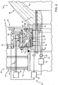
Figure 2 shows a larger-scale longitudinal section, with parts removed for clarity, of theFigure 1 wind turbine equipped with a bearing preload control system in accordance with the present invention; -
Figure 3 shows a larger-scale longitudinal section, with parts removed for clarity, of a detail of a variation of the present invention; -
Figure 4 shows a longitudinal section, with parts removed for clarity, of a wind turbine in accordance with a further embodiment of the present invention; -
Figure 5 shows a longitudinal section, with parts removed for clarity, of a wind turbine in accordance with a further embodiment of the present invention; -
Figure 6 shows a working life versus reload graph of the bearing. - Number 1 in
Figure 1 indicates as a whole a wind turbine for producing electric energy. Wind turbine 1 is a direct-drive type. In the example shown, wind turbine 1 comprises amain frame 2; a rotaryelectric machine 3; and ablade assembly 4 which rotates about an axis of rotation A. Rotaryelectric machine 3 is located betweenmain frame 2 andblade assembly 4 and, in addition to producing electric energy, serves, to supportblade assembly 4 and to transmit forces and moments induced byblade assembly 4 and rotaryelectric machine 3 itself tomain frame 2. - In the example shown,
main frame 2 is defiried by a curved,tubular nacelle 5 comprising acircular end flange 6 for connection to rotaryelectric machine 3; an end flange 7 for housing a pivot (not shown) for connection to a vertical support (not shown); and anopening 8 in the wall ofnacelle 5, through which to insert and remove large component parts. Preferably, opening 8 is substantially aligned withend flange 6. -
Blade assembly 4 comprises ahub 9 connected to rotaryelectric machine 3; and a plurality of blades (not shown in the drawings).Hub 9 comprises ahollow member 10 for supporting the blades (not shown); and aflange 11 for connection to rotaryelectric machine 3. - Rotary
electric machine 3 extends about axis of rotation A, and is substantially tubular, so as to form a passage between the hollowmain frame 2 andhollow hub 9. - Rotary
electric machine 3 comprises astator 12; arotor 13 located insidestator 12 and which rotates with respect tostator 12 about axis of rotation A. Rotaryelectric machine 3 comprises aframe 14 for connecting rotaryelectric machine 3 tomain frame 2, and for supportingblade assembly 4,stator 12, androtor 13. -
Frame 14 extends about axis of rotation A, and comprises atubular structure 15, which has acylindrical face 16 and is designed to support a tubularactive part 17 alongcylindrical face 16; anannular flange 18 for connecting rotaryelectric machine 3 tomain frame 2 of wind turbine 1; and aring 19 having anannular seat 20 for at least partly housing abearing 21. In the example shown, one bearing 21 supportsblade assembly 4 androtor 13 integral withblade assembly 4. - In other words,
frame 14 forms part oftubular stator 12, sincetubular structure 15 forms part oftubular stator 12. In fact,tubular stator 12 comprisestubular structure 15 andactive part 17. - Tubular
active part 17 is divided into a plurality of axialactive segments 22, each of which, in the example shown, has electric windings fitted to a ferromagnetic, substantially prismatic core extending predominantly parallel to axis of rotation A. -
Tubular structure 15 is cylindrical and extends about axis of rotation A..Annular flange 18 is coaxial withtubular structure 15 and smaller in diameter thancylindrical face 16. Andring 19 is coaxial withtubular structure 15 and smaller in diameter thanannular flange 18. -
Annular flange 18 is located inside the end oftubular structure 15, along axis of rotation A. -
Ring 19 is located inside the central area oftubular structure 15, along axis of rotation A. -
Tubular structure 15,annular flange 18 andring 19 are connected rigidly to one another byarms tubular structure 15 is connected toannular flange 18 byarms 23, which extend predominantly radially with a small axial component; andannular flange 18 is connected to ring 19 byarms 24, which extend predominantly axially with a small radial component. - Each
arm 23 comprises twoplates 25 parallel to each other and to axis of rotation A. And similarly, eacharm 24 comprises twoplates 26 also parallel to each other and to axis of rotation A. -
Annular flange 18 has aseat 27 for connection tomain frame 2 of wind turbine 1.Frame 14 andmain frame 2 are preferably connected by a bolted joint (not shown in the drawings) betweenannular flange 18 andend flange 6, and by which the forces and moments induced by rotaryelectric machine 3 andblade assembly 4 are transmitted tomain frame 2. - Rotary
electric machine 3, i.e. wind turbine 1, preferably has only bearing 21 to withstand the radial and axial loads transmitted fromtubular rotor 13 andblade assembly 4 tomain frame 2. - With reference to
Figure 2 , bearing 21 is a rolling bearing, comprises anouter ring 28 and aninner ring 29, and is housed inannular seat 20 ofring 19. More specifically,outer ring 28 is housed inannular seat 20, andinner ring 29 is connected totubular rotor 13.Annular seat 20 has a step profile, with cylindrical faces alternating with annular supporting faces. More specifically,outer ring 28 of bearing 21 is housed insideannular seat 20 and locked in place by alock ring 30 bolted to ring 19 andouter ring 28. -
Tubular rotor 13 comprises atubular structure 31 with acylindrical face 32; a tubularactive part 33; and aradial structure 34 located insidetubular structure 31 and connected to bearing 21, more specifically toinner ring 29 ofbearing 21. In other words,radial structure 34 is fixed, on one side, to bearing 21 and, on the opposite side, tohub 9, more specifically to flange 11 ofhub 9. -
Radial structure 34 is fixed to bearing 21 andhub 9 by two independently releasable bolted joints.Radial structure 34 is fixed using alock ring 35 designed to partly houseinner ring 29 of bearing 21, and the end ofradial structure 34 withflange 11 ofhub 9. - Tubular
active parts - One, bolted joint comprises bolts, one of which, indicated 36 (in
Figures 1 and2 ), engageslock ring 35,radial structure 34 ofrotor 13, andflange 11 ofhub 9. The other bolted joint Comprisesbolts 37, which only engageradial structure 34 ofrotor 13, andflange 11 of hub 9 (Figure 1 ). -
Radial structure 34 is also connectable by a joint, in particular a bolted joint, directly toring 19.Radial structure 34 is located close to aface 38 ofring 19, and bothradial structure 34 andring 19 are designed to be connected integrally to each other.Radial structure 34 andring 19 are connected to connecttubular rotor 13 directly to frame 14 when changingbearing 21. -
Frame 14 has anemergency bearing 39 located alongarms 24 and which is positioned contacting tubular rotor 13 - in the example shown,tubular structure 31. - Like
active part 17,active part 33 comprises axialactive segments 40, each of which, in the example shown, has permanent magnets fitted to respective magnetic guides, is prismatic in shape, and extends predominantly parallel to axis of rotation A. - Tubular rotary
electric machine 3 communicates directly withhollow hub 9, and is traversed by cooling air, which is indicated by arrows F, is appropriately blown inside rotaryelectric machine 3, and serves mainly to coolactive parts bearing 21 is assembled, and in particular theinner ring 29 area. To mitigate the effect of cooling air. F, wind turbine 1 comprises an insulatingcover 41 for insulating the area swept by cooling air F. In the example shown, insulatingcover 41 is tubular and applied to lockring 35. More specifically, insulatingcover 41 is also shaped to guide the flow of cooling air F. - In addition to
outer ring 28 andinner ring 29, bearing 21 also comprises rollingbodies 42 arranged in two rings. More specifically,inner ring 29 comprises two adjacent half-rings control system 43 for controlling the preload ofbearing 21. The term 'preload' is a general term intended to mean interference or clearance betweenouter ring 28,inner ring 29 and rollingbodies 42 ofbearing 21. The preload is divided into a radial preload and an axial preload with reference to axis of rotation A. On wind turbines, the bearing is normally assembled with interference. In the example shown, the preload is set at the assembly stage, by hot-fitting, with a small amount of interference,outer ring 28 insideseat 20 onring 19, andinner ring 29 inside a seat onlock ring 35. -
Lock ring 35 is also tightened toradial structure 34 bybolts 36. Tighteningbolts 36 brings half-rings -
Control system 43 comprises acontrol device 44 for controllingouter ring 28; acontrol device 45 for controllinginner ring 29; atemperature sensor 46 for detecting the temperature ofouter ring 28; atemperature sensor 47 for detecting the temperature ofinner ring 29; and a control unit, 48 for controllingcontrol devices outer ring 28 andinner ring 29. -
Outer ring 28 is the stationary part of bearing 21, whileinner ring 29 is integral withrotor 13 and, in use, rotates about axis of rotation A with respect toouter ring 28. -
Control device 44 comprises athermostat 49; aheat exchanger 50 close toouter ring 28; and connectinglines 51 betweenthermostat 49 andheat exchanger 50. - Similarly,
control device 45 comprises athermostat 52; aheat exchanger 53 close toinner ring 29; connectinglines 54 betweenthermostat 52 andheat exchanger 53; and arotary distributor 55 located along connectinglines 54 to connect the stationary part to the rotary part ofcontrol device 45. - In the example shown,
heat exchanger 53 is located along the inner face oflock ring 35. -
Control devices heat exchangers outer ring 28 andinner ring 29 respectively. - In a variation of the present invention,
control devices heat exchangers outer ring 28 andinner ring 29. -
Bearing 21 is selected on the basis of its capacity and other parameters, including operating temperature. And controlsystem 43 provides for maintaining the temperature ofouter ring 28 andinner ring 29 so as to keep the preload within a predetermined acceptance range I. - The algorithm implemented by
control system 43 is substantially based on the characteristics and the assembly conditions of bearing 21, on the thermal deformation of bearing 21 as a function of the temperature ofouter ring 28 andinner ring 29, and on the variations in preload as a function of said thermal deformation. Given this data, it is possible to calculate the preload as a function of the temperature ofouter ring 28 andinner ring 29. And the calculated preload is compared with the predetermined preload acceptance range I shown inFigure 6 . As shown inFigure 6 , the preload acceptance range I (x axis) is chosen to ensure a long predicted working life (y axis) ofbearing 21. -
Control unit 48 is programmable, and comprises a memory in which to store the characteristics ofbearing 21.Control unit 48 is configured to calculate the deformation of bearing 21 on the basis of the detected temperatures ofouter ring 28 andinner ring 29, and/or the difference between the detected temperatures ofouter ring 28 andinner ring 29.Control unit 48 is configured to calculate the preload on the basis of the thermal deformation ofouter ring 28 andinner ring 29; and to compare the calculated preload with preload acceptance range I. If the calculated preload does not fall within acceptance range I, the control unit commandsthermostats outer ring 28 8 and/orinner ring 29 to bring the preload back within acceptance range I. -
Control unit 48 is configured to memorize the temperature data ofouter ring 28 and inner 29 together with data detected and memorized by the control unit controlling wind turbine 1 as a whole, so as to determine any anomalous behaviour of bearing 21. For example, for a given external temperature, cooling system efficiency, wind speed, and blade angle, overheating of bearing 21 may be detected, and which may be considered anomalous in the light of other operating conditions. In which case,control unit 48 is configured to emit an alarm signal. - In very cold climates, and when wind turbine 1 is re-started, the temperatures of
outer ring 28 andinner ring 29 are below the optimum operating parameters of bearing 21, so both rings must be heated. - Other environmental and operating conditions make it necessary to heat
outer ring 28 andinner ring 29 differently. This differential temperature ofouter ring 28 andinner ring 29 is made possible bycontrol system 43. - In the
Figure 3 variation,heat exchanger 53 is located betweenlock ring 35 andinner ring 29 ofbearing 21. -
Number 56 inFigure 4 indicates a wind turbine for producing electric energy.Wind turbine 56 is a direct-drive type and, in the example shown, comprises a rotaryelectric machine 57; and ablade assembly 58 which rotates about an axis of rotation A. In addition to producing electric energy, rotaryelectric machine 57 also serves to supportblade assembly 58 and to transmit forces and moments induced byblade assembly 58 and rotaryelectric machine 57 itself to the main frame (not shown) ofwind turbine 56. -
Blade assembly 58 comprises ahub 59 connected to rotaryelectric machine 57; and a plurality of blades (not shown in the drawings).Hub 59 comprises ahollow member 60 for supporting the blades (not shown); and aflange 61 for connection to rotaryelectric machine 57. - Rotary
electric machine 57 is substantially tubular, so as to form a space for access tohollow hub 59. - Rotary
electric machine 57 comprises astator 62; and arotor 63 located insidestator 62.Stator 62 comprises aring 64 having anannular seat 65 for at least partly housing abearing 66; and aradial structure 67 for connectingring 64 to a tubular structure not shown in the drawings. In the example shown, onebearing 66supports blade assembly 58 androtor 63 integral withblade assembly 58. -
Rotor 63 comprises aring 68 with anannular seat 69 forhousing bearing 66; and aradial structure 70 for connectingring 68 to a further tubular structure not shown in the drawings. - Rotary
electric machine 57, i.e.wind turbine 56, preferably has only bearing 66 to withstand radial and axial forces and tipping moments.Bearing 66 is a rolling bearing and comprises anouter ring 71 and aninner ring 72. In the example shown, bearing 66 is a rolling bearing with two rings of rolling bodies 73 - in the example shown, rollers. More specifically,outer ring 71 is housed inannular seat 65, andinner ring 72 is housed inannular seat 69 onring 68 ofrotor 63.Outer ring 71 of bearing 66 is locked insideannular seat 65 by alock ring 74 bolted to ring 64 andouter ring 71. -
Inner ring 72 comprises two half-rings inside seat 69, and are locked axially by alock ring 75 and by a bolted joint by which to set the axial preload. -
Wind turbine 56 comprises acontrol system 43 as described with reference toFigure 2 .Heat exchanger 50 is housed inside grooves formed inring 64 ofstator 62, atannular seat 65, so as to directly contactouter ring 71. Likewise,heat exchanger 53 is housed inside grooves formed inring 68 ofrotor 63, atannular seat 69, so as to directly contactinner ring 72. -
Temperature sensor 46 is located inside a space inring 64, betweenring 64 andouter ring 71, and preferably along a front face ofouter ring 71, at a given distance fromheat exchanger 50. And likewise,temperature sensor 47 is located inside a space inring 68, preferably betweenring 68 andinner ring 72, preferably facing a front face ofinner ring 72, and at a given distance fromheat exchanger 53. -
Number 76 in theFigure 5 embodiment indicates a wind turbine for producing electric energy.Wind turbine 76 is a direct-drive type and, in the example shown, comprises a rotaryelectric machine 77; and ablade assembly 78 which rotates about an axis of rotation A. In addition to producing electric energy, rotaryelectric machine 77 also serves to supportblade assembly 78 and to transmit forces and moments induced byblade assembly 78 and rotaryelectric machine 77 itself to themain frame 79 ofwind turbine 76. -
Blade assembly 78 comprises ahollow hub 80 connected to rotaryelectric machine 77; and a plurality of blades (not shown in the drawings).Hub 80 comprises aflange 81 for connection to rotaryelectric machine 77. - Rotary
electric machine 77 extends about axis of rotation A, and is substantially tubular to form a space for access tohollow hub 80. - Rotary
electric machine 77 comprises astator 82; and arotor 83 located insidestator 62, and which rotates about axis of rotation A with respect tostator 82.Stator 82 comprises a tubular structure 84 having acylindrical face 85 and designed to support a tubularactive part 86 alongcylindrical face 85. -
Rotor 83 comprises atubular structure 87 with acylindrical face 88; and a tubularactive part 89 fitted tocylindrical face 88 oftubular structure 87. -
Tubular structures 84 and 87 are connected in rotary manner by twobearings tubular structures 84 and 87, which have reinforcing rings at the ends, and assembly rings.. Each bearing 90, 91 comprises anouter ring 92, ansinner ring 93, and a ring of rollingbodies 94.Bearing 90 is stressed more than bearing 91, is preloaded with interference, and is actively controlled bycontrol system 43. In this case, the grooveshousing heat exchangers tubular structures 84 and 87, at end seats ofbearings - Clearly, changes may be made to the control method and system and the wind turbine according to the present invention without, however, departing from the protective scope of the accompanying Claims. In particular, the control method and system described and claimed also apply to wind turbines, with overgears and with structures other than those described with reference to the attached drawings, and may also be used to advantage for controlling bearings other than those described.
Claims (25)
- A control method for controlling the preload of a wind turbine bearing, the method comprising the steps of estimating the preload on the bearing (21; 66; 90) as a function of the temperature of the outer ring (28; 71; 92) and the inner ring (29: 72; 93); comparing the estimated preload with a predetermined acceptance range (I); correcting the preload on the bearing (21; 66; 90) when the preload is outside the acceptance range (I); detecting the temperature of the outer ring (28; 71; 92); detecting the temperature of the inner ring (29; 72; 93); calculating the temperature difference between the outer ring (28; 71; 92) and the inner ring (29; 72; 93); controlling the temperature of the outer ring (28; 71; 92) and the inner ring (29; 72; 93) as a function of the temperature difference between the outer ring (28, 71; 92) and the inner ring (29; 72; 93) so as to keep the preload within the predetermined acceptance range (I).
- The control method as claimed in Claim 1, wherein the step of estimating the preload comprises calculating the preload on the basis of the structural, dimensional, and assembly characteristics, and the temperature of the bearing (21; 66; 90).
- The control method as claimed in Claim 1 or 2, wherein the step of correcting the preload comprises heating the outer ring (28; 71; 92).
- The control method as claimed in any one of the foregoing Claims, wherein the step of correcting the preload comprises cooling the outer ring (28; 71; 92).
- The control method as claimed in any one of the foregoing Claims, wherein the step of correcting the preload comprises heating the inner ring (29; 72; 93).
- The control method as claimed in any one of the foregoing Claims, wherein the step of correcting the preload comprises cooling the inner ring (29; 72; 93).
- The control method as claimed in any one of the foregoing Claims and comprising the step of controlling the temperature of the outer ring (28; 71; 92) as a function of the detected temperature of the outer ring (28; 71; 92).
- The control method as claimed in any one of the foregoing Claims and comprising the step of controlling the temperature of the inner ring (29; 72; 93) as a function of the detected temperature of the inner ring (29; 72; 93).
- A computer program loadable directly into a memory of a control unit (48) to perform the steps in the method in any one of Claims 1 to 8 when the program is implemented by the control unit (48).
- A software product comprising a readable medium on which the program in Claim 9 is stored.
- A control system for controlling the preload of a wind turbine bearing, the control system (43) comprising a control unit (48) configured to estimate the preload on the bearing (21; 66; 90) as a function of the temperature of the outer ring (28; 71; 92) and the inner ring (29: 72; 93); compare the estimated preload with a predetermined acceptance range (I); and correct the preload on the bearing (21; 66; 90) when the preload is outside the acceptance range (I); at least one first sensor (46) for detecting the temperature of the outer ring (28; 71; 92); at least one second sensor (47) for detecting the temperature of the inner ring (29; 72; 93, wherein the control unit (48) is configured to calculate the temperature difference between the outer ring (28; 71; 92) and the inner ring (29, 72 ; 93) and to control a first and a second control device (44, 45) to adjust the temperature of the outer ring (28, 71; 92) and the inner ring (29; 72; 93) respectively as a function of the temperature difference between the outer ring (28; 71; 92) and the inner ring (29; 72; 93) so as to keep the preload within the predetermined acceptance range (I).
- The control system as claimed in Claim 11, wherein the control unit (48) is configured to calculate the preload on the basis of the structural, dimensional, and assembly characteristics, and the temperature of the bearing (21; 66; 90).
- The control system as claimed in Claim 11 or 12, wherein the first control device (44) is configured to heat the outer ring (28; 71; 92) to correct the preload of the bearing (21; 66; 90).
- The control system as claimed in any one of Claims 11 to 13, wherein the first control device (44) is configured to cool the outer ring (28; 71; 92) to correct the preload on the bearing (21; 66; 90).
- The control system as claimed in any one of Claims 11 to 14, wherein the second control device (45) is configured to heat the inner ring (29; 72; 93) to correct the preload on the bearing (21; 66; 90).
- A control system as claimed in any one of Claims 11 to 15, wherein the second control device (45) is configured to cool the inner ring (29; 72; 93) to correct the preload on the bearing (21; 66; 90).
- A control system as claimed in any one of the Claims 11 to 16, wherein the control unit (48) is configured to control the first control device (44) to adjust the temperature of the outer ring (28; 71; 92) as a function of the detected temperature of the outer ring (28; 71; 92).
- A control system as claimed in any one of the claims 11 to 17, wherein the control unit (48) is configured to control the second control device (45) to adjust the temperature of the inner ring (29; 72; 93) as a function of the detected temperature the inner ring (29, 72, 93).
- A direct drive wind turbine for producing electric energy, the wind turbine (1; 56; 76) comprising a blade assembly (4; 58; 78) rotatable about an axis of rotation (A); a rotary electric machine (3; 57; 77) comprising a stator (12; 62; 82), and a rotor (13; 63; 83) connected to the blade assembly (4; 58; 78); a bearing (21; 66; 90) for supporting the blade assembly (4; 58; 78) about the axis of rotation (A); and a control system (43) configured to control the preload of the bearing (21; 66; 90) as claimed in any one of Claims 11 to 18.
- The wind turbine as claimed in Claim 19 and comprising thermal insulation of the bearing (21).
- The wind turbine as claimed in Claim 19 or 20, wherein the rotary electric machine (3) is a hollow tubular rotary electric machine, through which cooling air (F) flows along the axis of rotation (A), and comprises an insulating cover (41) at the inner ring (29).
- The wind turbine as claimed in any one of Claims 19 to 21, wherein the outer ring (28; 71; 92) is connected to the stator (12; 62; 82) and the inner ring (29; 72; 93) is connected to the rotor (13; 63; 83).
- The wind turbine as claimed in any one of Claims 19 to 22, wherein the stator (12; 82) comprises a first tubular structure (15; 84), and a tubular first active part (17; 86) connected to the first tubular structure (15; 84); and the rotor (13; 83) comprises a second tubular structure (31; 87), and a tubular second active part (33; 89), which is connected to the second tubular structure (31; 87), faces the first active part (17; 86), and is separated from the first active part (17; 86) by an air gap (T).
- The wind turbine as claimed in any one of Claims 19 to 23, wherein the bearing (21; 66; 90) is a rolling bearing for supporting radial and axial loads.
- The wind turbine as claimed in any one of' Claims 19 to 23, wherein the bearing (21; 66) comprises two rings of rolling bodies (42; 73); the rolling bodies (73) preferably being defined by rollers.
Applications Claiming Priority (2)
| Application Number | Priority Date | Filing Date | Title |
|---|---|---|---|
| IT001395A ITMI20121395A1 (en) | 2012-08-06 | 2012-08-06 | METHOD, PROGRAM, AND CONTROL SYSTEM FOR CHECKING THE PRE-LOAD OF A BEARING OF A AIRCONDITIONER AND AIRCONDITIONER INCLUDING SUCH CONTROL SYSTEM |
| PCT/IB2013/056443 WO2014024139A1 (en) | 2012-08-06 | 2013-08-06 | Control method, program and system for controlling the bearing preload of a wind turbine and wind turbine comprising such control system |
Publications (2)
| Publication Number | Publication Date |
|---|---|
| EP2880322A1 EP2880322A1 (en) | 2015-06-10 |
| EP2880322B1 true EP2880322B1 (en) | 2016-10-05 |
Family
ID=46939811
Family Applications (1)
| Application Number | Title | Priority Date | Filing Date |
|---|---|---|---|
| EP13777137.4A Active EP2880322B1 (en) | 2012-08-06 | 2013-08-06 | Control method, program and system for controlling the bearing preload of a wind turbine and wind turbine comprising such control system |
Country Status (10)
| Country | Link |
|---|---|
| US (1) | US10215227B2 (en) |
| EP (1) | EP2880322B1 (en) |
| AU (1) | AU2013301218A1 (en) |
| BR (1) | BR112015002669A2 (en) |
| DK (1) | DK2880322T3 (en) |
| IT (1) | ITMI20121395A1 (en) |
| MX (1) | MX2015001609A (en) |
| NZ (1) | NZ704484A (en) |
| PL (1) | PL2880322T3 (en) |
| WO (1) | WO2014024139A1 (en) |
Cited By (1)
| Publication number | Priority date | Publication date | Assignee | Title |
|---|---|---|---|---|
| US10215227B2 (en) | 2012-08-06 | 2019-02-26 | Windfin B.V. | Control method, program and system for controlling the bearing preload of a wind turbine and wind turbine comprising such control system |
Families Citing this family (11)
| Publication number | Priority date | Publication date | Assignee | Title |
|---|---|---|---|---|
| US9593670B2 (en) * | 2014-04-30 | 2017-03-14 | General Electric Company | System and methods for reducing wind turbine noise |
| EP2947312B1 (en) * | 2014-05-23 | 2019-09-25 | Siemens Gamesa Renewable Energy A/S | Method for operating a wind turbine |
| CN104832774B (en) * | 2015-04-22 | 2017-03-22 | 北京金风科创风电设备有限公司 | Heating device for protecting bearing of wind driven generator and bearing system |
| US9891136B2 (en) * | 2015-09-30 | 2018-02-13 | Deere & Company | Methods to determine a bearing setting |
| EP3387274B1 (en) * | 2015-12-11 | 2019-05-22 | SMS Group GmbH | Bearing block for holding a bearing for a roller |
| JP2017180687A (en) * | 2016-03-30 | 2017-10-05 | 株式会社 神崎高級工機製作所 | Rolling bearing-type transmission mechanism |
| EP3273077B1 (en) * | 2016-07-21 | 2020-06-03 | Aktiebolaget SKF | Rolling bearing with flange |
| CN107044390B (en) * | 2017-05-12 | 2023-10-13 | 北京金风科创风电设备有限公司 | Wind turbine generator and its cooling control method |
| CN108019324B (en) * | 2017-12-06 | 2019-07-09 | 北京金风科创风电设备有限公司 | Shafting cooling system, control method thereof and wind generating set |
| EP3904712B1 (en) * | 2020-04-28 | 2024-06-26 | Siemens Gamesa Renewable Energy A/S | Main bearing for a wind turbine |
| EP3919768A1 (en) * | 2020-06-03 | 2021-12-08 | Flender GmbH | Arrangement, method for mounting and simulating a rolling bearing |
Family Cites Families (15)
| Publication number | Priority date | Publication date | Assignee | Title |
|---|---|---|---|---|
| US6135641A (en) * | 1997-10-30 | 2000-10-24 | Honeywell International Inc. | Hybrid duplex bearing assembly having thermal compensation |
| JP3949801B2 (en) * | 1997-12-16 | 2007-07-25 | 東芝機械株式会社 | Bearing device for machine tool spindle |
| DE19944652B4 (en) * | 1999-09-17 | 2005-08-25 | Skf Gmbh | Method for operating a roller arrangement and bearing arrangement for a roller arrangement |
| JP2002054629A (en) * | 2000-08-11 | 2002-02-20 | Koyo Seiko Co Ltd | Pre-load adjustment device for rolling bearing |
| US7082772B2 (en) * | 2003-08-20 | 2006-08-01 | Directed Electronics, Inc. | Peltier temperature control system for electronic components |
| SE530523C2 (en) * | 2006-10-02 | 2008-07-01 | Metso Panelboard Ab | Rotary machine, refiner and method of vibration control of a rotary machine |
| JP2008157340A (en) * | 2006-12-22 | 2008-07-10 | Ntn Corp | Rolling bearing |
| EP1992829B2 (en) * | 2007-05-18 | 2017-01-18 | Fibro GmbH | Method for adjusting the initial tension of a ball bearing, ball bearing unit with adjustable initial tension and rotary table and spindle with corresponding ball bearing unit |
| US8469597B2 (en) * | 2008-04-16 | 2013-06-25 | Honeywell International Inc. | Active preload control for rolling element bearings |
| EP2341327B1 (en) * | 2008-10-15 | 2013-09-18 | NTN Corporation | Sensor-equipped bearing for wheel |
| GB2472619B (en) * | 2009-08-12 | 2015-07-29 | Romax Technology Ltd | Bearing cartridge |
| JP2012021574A (en) * | 2010-07-14 | 2012-02-02 | Ntn Corp | Bearing device |
| DE102011076099B4 (en) * | 2011-05-19 | 2012-12-06 | Aktiebolaget Skf | Method for operating a bearing arrangement |
| WO2013152850A1 (en) * | 2012-04-13 | 2013-10-17 | Eolotec Gmbh | Bearing arrangement and method for adjusting the preload of a bearing arrangement |
| ITMI20121395A1 (en) | 2012-08-06 | 2014-02-07 | Wilic Sarl | METHOD, PROGRAM, AND CONTROL SYSTEM FOR CHECKING THE PRE-LOAD OF A BEARING OF A AIRCONDITIONER AND AIRCONDITIONER INCLUDING SUCH CONTROL SYSTEM |
-
2012
- 2012-08-06 IT IT001395A patent/ITMI20121395A1/en unknown
-
2013
- 2013-08-06 BR BR112015002669A patent/BR112015002669A2/en not_active Application Discontinuation
- 2013-08-06 EP EP13777137.4A patent/EP2880322B1/en active Active
- 2013-08-06 PL PL13777137T patent/PL2880322T3/en unknown
- 2013-08-06 WO PCT/IB2013/056443 patent/WO2014024139A1/en not_active Ceased
- 2013-08-06 MX MX2015001609A patent/MX2015001609A/en unknown
- 2013-08-06 DK DK13777137.4T patent/DK2880322T3/en active
- 2013-08-06 US US14/419,860 patent/US10215227B2/en active Active
- 2013-08-06 AU AU2013301218A patent/AU2013301218A1/en not_active Abandoned
- 2013-08-06 NZ NZ704484A patent/NZ704484A/en not_active IP Right Cessation
Cited By (1)
| Publication number | Priority date | Publication date | Assignee | Title |
|---|---|---|---|---|
| US10215227B2 (en) | 2012-08-06 | 2019-02-26 | Windfin B.V. | Control method, program and system for controlling the bearing preload of a wind turbine and wind turbine comprising such control system |
Also Published As
| Publication number | Publication date |
|---|---|
| NZ704484A (en) | 2017-12-22 |
| US20150211572A1 (en) | 2015-07-30 |
| MX2015001609A (en) | 2015-11-16 |
| WO2014024139A1 (en) | 2014-02-13 |
| BR112015002669A2 (en) | 2019-07-30 |
| EP2880322A1 (en) | 2015-06-10 |
| ITMI20121395A1 (en) | 2014-02-07 |
| US10215227B2 (en) | 2019-02-26 |
| PL2880322T3 (en) | 2017-02-28 |
| DK2880322T3 (en) | 2017-01-02 |
| AU2013301218A1 (en) | 2015-02-26 |
Similar Documents
| Publication | Publication Date | Title |
|---|---|---|
| US10215227B2 (en) | Control method, program and system for controlling the bearing preload of a wind turbine and wind turbine comprising such control system | |
| US8177483B2 (en) | Active casing alignment control system and method | |
| US20100296912A1 (en) | Active Rotor Alignment Control System And Method | |
| EP2605379B1 (en) | System and Method for Cooling Dynamoelectric Machine | |
| EP3754218B1 (en) | Bearing device and spindle device | |
| JP6124508B2 (en) | Direct drive wind turbine with thermal control system, bearing assembly and method for controlling the temperature of a direct drive wind turbine | |
| CN104121287B (en) | Control the device in the gap of sliding bearing | |
| EP3012415B1 (en) | Turbo machine with thermal expansion control and method for operating such turbo machine | |
| EP3568602B1 (en) | Active radial magnetic bearing assembly with internal sensors | |
| EP3514375B1 (en) | Shafting cooling system and method for controlling same, and wind power generator set | |
| EP2947352B1 (en) | A gear unit and a method for heating lubricant oil of a gear unit | |
| US20170158298A1 (en) | Pod propulsion device and a method for cooling such | |
| CN102287609A (en) | Low-temperature rotating device and operating method of same | |
| CN112018955A (en) | Motor temperature control device and method | |
| CN101765719A (en) | Method of positioning seals in turbomachinery utilizing electromagnetic bearings | |
| EP2947312B1 (en) | Method for operating a wind turbine | |
| KR20150123257A (en) | Wind power generation device | |
| CN103769796B (en) | A kind of megawatt wind turbine generator main shaft holds inside and outside circle heating means simultaneously | |
| KR20190133772A (en) | Method for cooling a gearless wind turbine | |
| US20170234164A1 (en) | Rotary machine unit | |
| EP3790174A1 (en) | Stator of an electrical machine with removable temperature sensor | |
| EP2899858B1 (en) | Electric generator arrangement with improved cooling system and operating method thereto | |
| KR101331279B1 (en) | Variable impeller using bi-metal | |
| JP2013150374A (en) | Bearing device of rotary electric machine | |
| KR20190094928A (en) | DRAFT ROLLER and INDUCTION HEATING ROLLER DEVICE USING OF THE SAME |
Legal Events
| Date | Code | Title | Description |
|---|---|---|---|
| PUAI | Public reference made under article 153(3) epc to a published international application that has entered the european phase |
Free format text: ORIGINAL CODE: 0009012 |
|
| 17P | Request for examination filed |
Effective date: 20150204 |
|
| AK | Designated contracting states |
Kind code of ref document: A1 Designated state(s): AL AT BE BG CH CY CZ DE DK EE ES FI FR GB GR HR HU IE IS IT LI LT LU LV MC MK MT NL NO PL PT RO RS SE SI SK SM TR |
|
| AX | Request for extension of the european patent |
Extension state: BA ME |
|
| DAX | Request for extension of the european patent (deleted) | ||
| REG | Reference to a national code |
Ref country code: DE Ref legal event code: R079 Ref document number: 602013012510 Country of ref document: DE Free format text: PREVIOUS MAIN CLASS: F16C0029060000 Ipc: F16C0019520000 |
|
| GRAP | Despatch of communication of intention to grant a patent |
Free format text: ORIGINAL CODE: EPIDOSNIGR1 |
|
| RIC1 | Information provided on ipc code assigned before grant |
Ipc: F03D 7/00 20060101ALI20160303BHEP Ipc: F16C 19/52 20060101AFI20160303BHEP Ipc: F03D 9/00 20160101ALI20160303BHEP Ipc: F03D 7/04 20060101ALI20160303BHEP Ipc: F16C 25/08 20060101ALI20160303BHEP Ipc: F16C 37/00 20060101ALI20160303BHEP |
|
| INTG | Intention to grant announced |
Effective date: 20160324 |
|
| GRAS | Grant fee paid |
Free format text: ORIGINAL CODE: EPIDOSNIGR3 |
|
| GRAA | (expected) grant |
Free format text: ORIGINAL CODE: 0009210 |
|
| AK | Designated contracting states |
Kind code of ref document: B1 Designated state(s): AL AT BE BG CH CY CZ DE DK EE ES FI FR GB GR HR HU IE IS IT LI LT LU LV MC MK MT NL NO PL PT RO RS SE SI SK SM TR |
|
| REG | Reference to a national code |
Ref country code: GB Ref legal event code: FG4D |
|
| REG | Reference to a national code |
Ref country code: CH Ref legal event code: EP |
|
| REG | Reference to a national code |
Ref country code: AT Ref legal event code: REF Ref document number: 834938 Country of ref document: AT Kind code of ref document: T Effective date: 20161015 |
|
| REG | Reference to a national code |
Ref country code: IE Ref legal event code: FG4D |
|
| REG | Reference to a national code |
Ref country code: DE Ref legal event code: R096 Ref document number: 602013012510 Country of ref document: DE |
|
| REG | Reference to a national code |
Ref country code: NL Ref legal event code: FP |
|
| REG | Reference to a national code |
Ref country code: DK Ref legal event code: T3 Effective date: 20161227 |
|
| REG | Reference to a national code |
Ref country code: LT Ref legal event code: MG4D |
|
| PG25 | Lapsed in a contracting state [announced via postgrant information from national office to epo] |
Ref country code: LV Free format text: LAPSE BECAUSE OF FAILURE TO SUBMIT A TRANSLATION OF THE DESCRIPTION OR TO PAY THE FEE WITHIN THE PRESCRIBED TIME-LIMIT Effective date: 20161005 |
|
| PG25 | Lapsed in a contracting state [announced via postgrant information from national office to epo] |
Ref country code: GR Free format text: LAPSE BECAUSE OF FAILURE TO SUBMIT A TRANSLATION OF THE DESCRIPTION OR TO PAY THE FEE WITHIN THE PRESCRIBED TIME-LIMIT Effective date: 20170106 Ref country code: LT Free format text: LAPSE BECAUSE OF FAILURE TO SUBMIT A TRANSLATION OF THE DESCRIPTION OR TO PAY THE FEE WITHIN THE PRESCRIBED TIME-LIMIT Effective date: 20161005 Ref country code: NO Free format text: LAPSE BECAUSE OF FAILURE TO SUBMIT A TRANSLATION OF THE DESCRIPTION OR TO PAY THE FEE WITHIN THE PRESCRIBED TIME-LIMIT Effective date: 20170105 Ref country code: SE Free format text: LAPSE BECAUSE OF FAILURE TO SUBMIT A TRANSLATION OF THE DESCRIPTION OR TO PAY THE FEE WITHIN THE PRESCRIBED TIME-LIMIT Effective date: 20161005 |
|
| PG25 | Lapsed in a contracting state [announced via postgrant information from national office to epo] |
Ref country code: PT Free format text: LAPSE BECAUSE OF FAILURE TO SUBMIT A TRANSLATION OF THE DESCRIPTION OR TO PAY THE FEE WITHIN THE PRESCRIBED TIME-LIMIT Effective date: 20170206 Ref country code: ES Free format text: LAPSE BECAUSE OF FAILURE TO SUBMIT A TRANSLATION OF THE DESCRIPTION OR TO PAY THE FEE WITHIN THE PRESCRIBED TIME-LIMIT Effective date: 20161005 Ref country code: IS Free format text: LAPSE BECAUSE OF FAILURE TO SUBMIT A TRANSLATION OF THE DESCRIPTION OR TO PAY THE FEE WITHIN THE PRESCRIBED TIME-LIMIT Effective date: 20170205 Ref country code: HR Free format text: LAPSE BECAUSE OF FAILURE TO SUBMIT A TRANSLATION OF THE DESCRIPTION OR TO PAY THE FEE WITHIN THE PRESCRIBED TIME-LIMIT Effective date: 20161005 Ref country code: BE Free format text: LAPSE BECAUSE OF FAILURE TO SUBMIT A TRANSLATION OF THE DESCRIPTION OR TO PAY THE FEE WITHIN THE PRESCRIBED TIME-LIMIT Effective date: 20161005 Ref country code: RS Free format text: LAPSE BECAUSE OF FAILURE TO SUBMIT A TRANSLATION OF THE DESCRIPTION OR TO PAY THE FEE WITHIN THE PRESCRIBED TIME-LIMIT Effective date: 20161005 Ref country code: FI Free format text: LAPSE BECAUSE OF FAILURE TO SUBMIT A TRANSLATION OF THE DESCRIPTION OR TO PAY THE FEE WITHIN THE PRESCRIBED TIME-LIMIT Effective date: 20161005 |
|
| REG | Reference to a national code |
Ref country code: DE Ref legal event code: R097 Ref document number: 602013012510 Country of ref document: DE |
|
| PG25 | Lapsed in a contracting state [announced via postgrant information from national office to epo] |
Ref country code: SK Free format text: LAPSE BECAUSE OF FAILURE TO SUBMIT A TRANSLATION OF THE DESCRIPTION OR TO PAY THE FEE WITHIN THE PRESCRIBED TIME-LIMIT Effective date: 20161005 Ref country code: RO Free format text: LAPSE BECAUSE OF FAILURE TO SUBMIT A TRANSLATION OF THE DESCRIPTION OR TO PAY THE FEE WITHIN THE PRESCRIBED TIME-LIMIT Effective date: 20161005 Ref country code: CZ Free format text: LAPSE BECAUSE OF FAILURE TO SUBMIT A TRANSLATION OF THE DESCRIPTION OR TO PAY THE FEE WITHIN THE PRESCRIBED TIME-LIMIT Effective date: 20161005 Ref country code: EE Free format text: LAPSE BECAUSE OF FAILURE TO SUBMIT A TRANSLATION OF THE DESCRIPTION OR TO PAY THE FEE WITHIN THE PRESCRIBED TIME-LIMIT Effective date: 20161005 |
|
| PLBE | No opposition filed within time limit |
Free format text: ORIGINAL CODE: 0009261 |
|
| STAA | Information on the status of an ep patent application or granted ep patent |
Free format text: STATUS: NO OPPOSITION FILED WITHIN TIME LIMIT |
|
| REG | Reference to a national code |
Ref country code: FR Ref legal event code: PLFP Year of fee payment: 5 |
|
| PG25 | Lapsed in a contracting state [announced via postgrant information from national office to epo] |
Ref country code: BG Free format text: LAPSE BECAUSE OF FAILURE TO SUBMIT A TRANSLATION OF THE DESCRIPTION OR TO PAY THE FEE WITHIN THE PRESCRIBED TIME-LIMIT Effective date: 20170105 Ref country code: SM Free format text: LAPSE BECAUSE OF FAILURE TO SUBMIT A TRANSLATION OF THE DESCRIPTION OR TO PAY THE FEE WITHIN THE PRESCRIBED TIME-LIMIT Effective date: 20161005 |
|
| 26N | No opposition filed |
Effective date: 20170706 |
|
| PGFP | Annual fee paid to national office [announced via postgrant information from national office to epo] |
Ref country code: GB Payment date: 20170830 Year of fee payment: 5 |
|
| PG25 | Lapsed in a contracting state [announced via postgrant information from national office to epo] |
Ref country code: SI Free format text: LAPSE BECAUSE OF FAILURE TO SUBMIT A TRANSLATION OF THE DESCRIPTION OR TO PAY THE FEE WITHIN THE PRESCRIBED TIME-LIMIT Effective date: 20161005 |
|
| PGFP | Annual fee paid to national office [announced via postgrant information from national office to epo] |
Ref country code: NL Payment date: 20170828 Year of fee payment: 5 Ref country code: DK Payment date: 20170828 Year of fee payment: 5 |
|
| REG | Reference to a national code |
Ref country code: CH Ref legal event code: PL |
|
| PG25 | Lapsed in a contracting state [announced via postgrant information from national office to epo] |
Ref country code: MC Free format text: LAPSE BECAUSE OF FAILURE TO SUBMIT A TRANSLATION OF THE DESCRIPTION OR TO PAY THE FEE WITHIN THE PRESCRIBED TIME-LIMIT Effective date: 20161005 |
|
| PG25 | Lapsed in a contracting state [announced via postgrant information from national office to epo] |
Ref country code: LI Free format text: LAPSE BECAUSE OF NON-PAYMENT OF DUE FEES Effective date: 20170831 Ref country code: CH Free format text: LAPSE BECAUSE OF NON-PAYMENT OF DUE FEES Effective date: 20170831 |
|
| REG | Reference to a national code |
Ref country code: IE Ref legal event code: MM4A |
|
| PG25 | Lapsed in a contracting state [announced via postgrant information from national office to epo] |
Ref country code: LU Free format text: LAPSE BECAUSE OF NON-PAYMENT OF DUE FEES Effective date: 20170806 |
|
| PG25 | Lapsed in a contracting state [announced via postgrant information from national office to epo] |
Ref country code: IE Free format text: LAPSE BECAUSE OF NON-PAYMENT OF DUE FEES Effective date: 20170806 |
|
| REG | Reference to a national code |
Ref country code: FR Ref legal event code: PLFP Year of fee payment: 6 |
|
| PG25 | Lapsed in a contracting state [announced via postgrant information from national office to epo] |
Ref country code: MT Free format text: LAPSE BECAUSE OF NON-PAYMENT OF DUE FEES Effective date: 20170806 |
|
| REG | Reference to a national code |
Ref country code: AT Ref legal event code: UEP Ref document number: 834938 Country of ref document: AT Kind code of ref document: T Effective date: 20161005 |
|
| REG | Reference to a national code |
Ref country code: DK Ref legal event code: EBP Effective date: 20180831 |
|
| REG | Reference to a national code |
Ref country code: NL Ref legal event code: MM Effective date: 20180901 |
|
| GBPC | Gb: european patent ceased through non-payment of renewal fee |
Effective date: 20180806 |
|
| PG25 | Lapsed in a contracting state [announced via postgrant information from national office to epo] |
Ref country code: NL Free format text: LAPSE BECAUSE OF NON-PAYMENT OF DUE FEES Effective date: 20180901 Ref country code: HU Free format text: LAPSE BECAUSE OF FAILURE TO SUBMIT A TRANSLATION OF THE DESCRIPTION OR TO PAY THE FEE WITHIN THE PRESCRIBED TIME-LIMIT; INVALID AB INITIO Effective date: 20130806 |
|
| PG25 | Lapsed in a contracting state [announced via postgrant information from national office to epo] |
Ref country code: DK Free format text: LAPSE BECAUSE OF NON-PAYMENT OF DUE FEES Effective date: 20180831 |
|
| PG25 | Lapsed in a contracting state [announced via postgrant information from national office to epo] |
Ref country code: CY Free format text: LAPSE BECAUSE OF FAILURE TO SUBMIT A TRANSLATION OF THE DESCRIPTION OR TO PAY THE FEE WITHIN THE PRESCRIBED TIME-LIMIT Effective date: 20161005 Ref country code: GB Free format text: LAPSE BECAUSE OF NON-PAYMENT OF DUE FEES Effective date: 20180806 |
|
| PG25 | Lapsed in a contracting state [announced via postgrant information from national office to epo] |
Ref country code: MK Free format text: LAPSE BECAUSE OF FAILURE TO SUBMIT A TRANSLATION OF THE DESCRIPTION OR TO PAY THE FEE WITHIN THE PRESCRIBED TIME-LIMIT Effective date: 20161005 |
|
| PG25 | Lapsed in a contracting state [announced via postgrant information from national office to epo] |
Ref country code: AL Free format text: LAPSE BECAUSE OF FAILURE TO SUBMIT A TRANSLATION OF THE DESCRIPTION OR TO PAY THE FEE WITHIN THE PRESCRIBED TIME-LIMIT Effective date: 20161005 |
|
| P01 | Opt-out of the competence of the unified patent court (upc) registered |
Effective date: 20230518 |
|
| PGFP | Annual fee paid to national office [announced via postgrant information from national office to epo] |
Ref country code: DE Payment date: 20250827 Year of fee payment: 13 |
|
| PGFP | Annual fee paid to national office [announced via postgrant information from national office to epo] |
Ref country code: TR Payment date: 20250718 Year of fee payment: 13 Ref country code: IT Payment date: 20250709 Year of fee payment: 13 Ref country code: PL Payment date: 20250711 Year of fee payment: 13 |
|
| PGFP | Annual fee paid to national office [announced via postgrant information from national office to epo] |
Ref country code: FR Payment date: 20250825 Year of fee payment: 13 Ref country code: AT Payment date: 20250819 Year of fee payment: 13 |
|
| REG | Reference to a national code |
Ref country code: DE Ref legal event code: R081 Ref document number: 602013012510 Country of ref document: DE Owner name: LEITNER S.P.A., VIPITENO, IT Free format text: FORMER OWNER: WINDFIN B.V., LEIMUIDEN, NL |