EP2880284B1 - Wärmetauscher für einen ladeluftkühler - Google Patents
Wärmetauscher für einen ladeluftkühler Download PDFInfo
- Publication number
- EP2880284B1 EP2880284B1 EP13737933.5A EP13737933A EP2880284B1 EP 2880284 B1 EP2880284 B1 EP 2880284B1 EP 13737933 A EP13737933 A EP 13737933A EP 2880284 B1 EP2880284 B1 EP 2880284B1
- Authority
- EP
- European Patent Office
- Prior art keywords
- assembly
- heat exchanger
- segments
- intercooler
- extending
- Prior art date
- Legal status (The legal status is an assumption and is not a legal conclusion. Google has not performed a legal analysis and makes no representation as to the accuracy of the status listed.)
- Active
Links
- 239000000463 material Substances 0.000 claims description 12
- 239000012530 fluid Substances 0.000 description 20
- 238000000034 method Methods 0.000 description 16
- XLYOFNOQVPJJNP-UHFFFAOYSA-N water Substances O XLYOFNOQVPJJNP-UHFFFAOYSA-N 0.000 description 10
- 238000000605 extraction Methods 0.000 description 9
- 238000010248 power generation Methods 0.000 description 8
- 238000003809 water extraction Methods 0.000 description 7
- 238000001816 cooling Methods 0.000 description 6
- 239000007789 gas Substances 0.000 description 5
- 239000000567 combustion gas Substances 0.000 description 4
- 238000009434 installation Methods 0.000 description 4
- 230000004323 axial length Effects 0.000 description 3
- 238000005219 brazing Methods 0.000 description 3
- 238000004519 manufacturing process Methods 0.000 description 3
- 238000012986 modification Methods 0.000 description 3
- 230000004048 modification Effects 0.000 description 3
- 239000002245 particle Substances 0.000 description 3
- 238000007906 compression Methods 0.000 description 2
- 239000012809 cooling fluid Substances 0.000 description 2
- 238000010438 heat treatment Methods 0.000 description 2
- 238000005304 joining Methods 0.000 description 2
- 229910052782 aluminium Inorganic materials 0.000 description 1
- XAGFODPZIPBFFR-UHFFFAOYSA-N aluminium Chemical compound [Al] XAGFODPZIPBFFR-UHFFFAOYSA-N 0.000 description 1
- 230000006835 compression Effects 0.000 description 1
- 230000008602 contraction Effects 0.000 description 1
- 238000009826 distribution Methods 0.000 description 1
- 239000000446 fuel Substances 0.000 description 1
- 230000005484 gravity Effects 0.000 description 1
- 239000007788 liquid Substances 0.000 description 1
- 229910052751 metal Inorganic materials 0.000 description 1
- 239000002184 metal Substances 0.000 description 1
- 238000004806 packaging method and process Methods 0.000 description 1
- 230000035515 penetration Effects 0.000 description 1
- 238000010792 warming Methods 0.000 description 1
Images





Classifications
-
- F—MECHANICAL ENGINEERING; LIGHTING; HEATING; WEAPONS; BLASTING
- F02—COMBUSTION ENGINES; HOT-GAS OR COMBUSTION-PRODUCT ENGINE PLANTS
- F02C—GAS-TURBINE PLANTS; AIR INTAKES FOR JET-PROPULSION PLANTS; CONTROLLING FUEL SUPPLY IN AIR-BREATHING JET-PROPULSION PLANTS
- F02C7/00—Features, components parts, details or accessories, not provided for in, or of interest apart form groups F02C1/00 - F02C6/00; Air intakes for jet-propulsion plants
- F02C7/12—Cooling of plants
- F02C7/14—Cooling of plants of fluids in the plant, e.g. lubricant or fuel
- F02C7/141—Cooling of plants of fluids in the plant, e.g. lubricant or fuel of working fluid
- F02C7/143—Cooling of plants of fluids in the plant, e.g. lubricant or fuel of working fluid before or between the compressor stages
-
- F—MECHANICAL ENGINEERING; LIGHTING; HEATING; WEAPONS; BLASTING
- F28—HEAT EXCHANGE IN GENERAL
- F28D—HEAT-EXCHANGE APPARATUS, NOT PROVIDED FOR IN ANOTHER SUBCLASS, IN WHICH THE HEAT-EXCHANGE MEDIA DO NOT COME INTO DIRECT CONTACT
- F28D7/00—Heat-exchange apparatus having stationary tubular conduit assemblies for both heat-exchange media, the media being in contact with different sides of a conduit wall
- F28D7/0041—Heat-exchange apparatus having stationary tubular conduit assemblies for both heat-exchange media, the media being in contact with different sides of a conduit wall the conduits for only one medium being tubes having parts touching each other or tubes assembled in panel form
-
- F—MECHANICAL ENGINEERING; LIGHTING; HEATING; WEAPONS; BLASTING
- F28—HEAT EXCHANGE IN GENERAL
- F28D—HEAT-EXCHANGE APPARATUS, NOT PROVIDED FOR IN ANOTHER SUBCLASS, IN WHICH THE HEAT-EXCHANGE MEDIA DO NOT COME INTO DIRECT CONTACT
- F28D7/00—Heat-exchange apparatus having stationary tubular conduit assemblies for both heat-exchange media, the media being in contact with different sides of a conduit wall
- F28D7/005—Heat-exchange apparatus having stationary tubular conduit assemblies for both heat-exchange media, the media being in contact with different sides of a conduit wall the conduits for only one medium being tubes having bent portions or being assembled from bent tubes or being tubes having a toroidal configuration
-
- F—MECHANICAL ENGINEERING; LIGHTING; HEATING; WEAPONS; BLASTING
- F28—HEAT EXCHANGE IN GENERAL
- F28F—DETAILS OF HEAT-EXCHANGE AND HEAT-TRANSFER APPARATUS, OF GENERAL APPLICATION
- F28F1/00—Tubular elements; Assemblies of tubular elements
- F28F1/02—Tubular elements of cross-section which is non-circular
- F28F1/022—Tubular elements of cross-section which is non-circular with multiple channels
-
- F—MECHANICAL ENGINEERING; LIGHTING; HEATING; WEAPONS; BLASTING
- F28—HEAT EXCHANGE IN GENERAL
- F28F—DETAILS OF HEAT-EXCHANGE AND HEAT-TRANSFER APPARATUS, OF GENERAL APPLICATION
- F28F1/00—Tubular elements; Assemblies of tubular elements
- F28F1/10—Tubular elements and assemblies thereof with means for increasing heat-transfer area, e.g. with fins, with projections, with recesses
- F28F1/12—Tubular elements and assemblies thereof with means for increasing heat-transfer area, e.g. with fins, with projections, with recesses the means being only outside the tubular element
- F28F1/24—Tubular elements and assemblies thereof with means for increasing heat-transfer area, e.g. with fins, with projections, with recesses the means being only outside the tubular element and extending transversely
- F28F1/26—Tubular elements and assemblies thereof with means for increasing heat-transfer area, e.g. with fins, with projections, with recesses the means being only outside the tubular element and extending transversely the means being integral with the element
-
- F—MECHANICAL ENGINEERING; LIGHTING; HEATING; WEAPONS; BLASTING
- F05—INDEXING SCHEMES RELATING TO ENGINES OR PUMPS IN VARIOUS SUBCLASSES OF CLASSES F01-F04
- F05D—INDEXING SCHEME FOR ASPECTS RELATING TO NON-POSITIVE-DISPLACEMENT MACHINES OR ENGINES, GAS-TURBINES OR JET-PROPULSION PLANTS
- F05D2260/00—Function
- F05D2260/20—Heat transfer, e.g. cooling
- F05D2260/211—Heat transfer, e.g. cooling by intercooling, e.g. during a compression cycle
-
- F—MECHANICAL ENGINEERING; LIGHTING; HEATING; WEAPONS; BLASTING
- F05—INDEXING SCHEMES RELATING TO ENGINES OR PUMPS IN VARIOUS SUBCLASSES OF CLASSES F01-F04
- F05D—INDEXING SCHEME FOR ASPECTS RELATING TO NON-POSITIVE-DISPLACEMENT MACHINES OR ENGINES, GAS-TURBINES OR JET-PROPULSION PLANTS
- F05D2260/00—Function
- F05D2260/20—Heat transfer, e.g. cooling
- F05D2260/213—Heat transfer, e.g. cooling by the provision of a heat exchanger within the cooling circuit
-
- F—MECHANICAL ENGINEERING; LIGHTING; HEATING; WEAPONS; BLASTING
- F28—HEAT EXCHANGE IN GENERAL
- F28D—HEAT-EXCHANGE APPARATUS, NOT PROVIDED FOR IN ANOTHER SUBCLASS, IN WHICH THE HEAT-EXCHANGE MEDIA DO NOT COME INTO DIRECT CONTACT
- F28D21/00—Heat-exchange apparatus not covered by any of the groups F28D1/00 - F28D20/00
- F28D2021/0019—Other heat exchangers for particular applications; Heat exchange systems not otherwise provided for
- F28D2021/0026—Other heat exchangers for particular applications; Heat exchange systems not otherwise provided for for combustion engines, e.g. for gas turbines or for Stirling engines
-
- F—MECHANICAL ENGINEERING; LIGHTING; HEATING; WEAPONS; BLASTING
- F28—HEAT EXCHANGE IN GENERAL
- F28F—DETAILS OF HEAT-EXCHANGE AND HEAT-TRANSFER APPARATUS, OF GENERAL APPLICATION
- F28F2215/00—Fins
-
- F—MECHANICAL ENGINEERING; LIGHTING; HEATING; WEAPONS; BLASTING
- F28—HEAT EXCHANGE IN GENERAL
- F28F—DETAILS OF HEAT-EXCHANGE AND HEAT-TRANSFER APPARATUS, OF GENERAL APPLICATION
- F28F7/00—Elements not covered by group F28F1/00, F28F3/00 or F28F5/00
- F28F7/02—Blocks traversed by passages for heat-exchange media
-
- Y—GENERAL TAGGING OF NEW TECHNOLOGICAL DEVELOPMENTS; GENERAL TAGGING OF CROSS-SECTIONAL TECHNOLOGIES SPANNING OVER SEVERAL SECTIONS OF THE IPC; TECHNICAL SUBJECTS COVERED BY FORMER USPC CROSS-REFERENCE ART COLLECTIONS [XRACs] AND DIGESTS
- Y02—TECHNOLOGIES OR APPLICATIONS FOR MITIGATION OR ADAPTATION AGAINST CLIMATE CHANGE
- Y02T—CLIMATE CHANGE MITIGATION TECHNOLOGIES RELATED TO TRANSPORTATION
- Y02T50/00—Aeronautics or air transport
- Y02T50/60—Efficient propulsion technologies, e.g. for aircraft
Definitions
- Present embodiments relate generally to heat exchangers. More specifically present embodiments relate to a heat exchanger intercooler which may conform to various duct shapes, reduces footprint of current intercooler systems and may be installed inline with the turbine shaft or maybe offset from the turbine axis.
- air is pressurized in a compressor and mixed with fuel in a combustor for generating hot combustion gases which flow downstream and expand through turbine stages. These turbine stages extract energy from the combustion gases during the expansion the pressure of the combustion gas is reduced.
- the combustion gas may continue through multiple low stage turbines.
- One or more turbine shafts connects to the one or more compressor stages to operate the compressor.
- Turbine engines are utilized generally in the power industry to create energy which is utilized in communities' residential and commercial use. These turbine systems may utilize a heat exchanger intercooler in order to cool temperature of air passing through the turbine engine during the power generation process.
- An intercooler is a mechanical device used to cool a fluid, including liquids or gasses, between stages of a multi-stage compression process, typically a heat exchanger that removes heat. They are used in many applications, including air compressors for example of a turbine engine, to improve their volumetric efficiency by increasing intake air charge density through nearly isobaric (constant pressure) cooling.
- heat exchangers of current intercooler systems utilize welded or brazed fin connections to structures wherein fluid may pass through for cooling.
- the process of brazing multiple fins along the fluid carrying ducts is time consuming tedious and very expensive for manufacturing.
- EP 1916399 A2 discloses a heat exchanger assembly for a gas turbine engine.
- WO 2010/099535 A2 discloses a heat exchanger which includes a large number of small, closely-spaced modules.
- US 2008/289809 A1 discloses a heat exchanger having an aluminum main body.
- FIGS. 1-14 various embodiments of a gas turbine engine are depicted having a duct conforming fin heat exchanger intercooler.
- the intercooler allows for in line, or off-engine, installation with the turbine engine and has features which reduces costs of manufacturing, installation and costs associated with installation, such as property costs and shipping related costs. Other uses are well within the scope of this disclosure.
- the terms fore and aft are used with respect to the engine axis and generally mean toward the front of the turbine engine or the rear of the turbine engine in the direction of the engine axis, respectively.
- the term radially is used generally to indicate a direction perpendicular to an engine axis.
- FIG. 1 an isometric view of a volumetric duct conforming fin heat exchanger intercooler 30 is depicted.
- the intercooler 30 is utilized in a power plant for power generation or alternatively the structure may be configured for use in aviation or other areas utilizing gas turbine engines.
- the intercooler 30 includes an inlet end 32 and an outlet end 34 extending between the inlet and outlet is a housing 36 wherein a heat exchanger 40 is disposed.
- the intercooler 30 is utilized to cool air in compression stages before engaging the turbine structures utilized in power generation for other processes wherein a gas turbine engine is utilized.
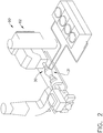
- FIG. 2 an isometric layout is shown of typical plant having a power generation turbine engine wherein a heat exchange intercooler 30 may be utilized.
- the embodiment provides that the intercooler 30 is disposed in line with the turbine shaft axis for power generation.
- the heat exchanger intercooler 30 is positioned in line with the axis of the compressor and turbine structure of the exemplary power plant depicted.
- the advantage of such configuration is that the airflow being cooled may be done so inline (31), i.e. aligned with the turbine shaft, and does not have to be moved off-alignment (131) of the turbine and compressor system. This reduces the tremendous cost associated with the duct typically required for this task.
- the intercooler 30 has a smaller footprint than existing intercooler systems and therefore less plant property is needed to position the intercooler 30.
- the intercooler 30 may be positioned in various locations. Although three intercoolers 30 are depicted, these may be used individually with a system in general and therefore the figure depicts various locations that the intercoolers 30 may be disposed. The figure should not be construed to require three separate intercoolers utilized.
- the intercoolers 30 are depicted off line or off axis from the compressor and turbine axis of the power plant.
- the structure may be disposed in either of the two ducts traditionally utilized with known intercooler designs or may be positioned in replacement of known intercooler designs at ends of the ducts shown.
- the ducts may be circular or other geometrically shaped cross-sections and further may be straight ducts or curved. Thus the heat exchanger is duct conforming in both the in line and the off axis designs.
- the heat exchanger 40 is disposed within the intercooler 30 as previously described and an airflow passes over an outside of the heat exchanger 40 to cool the airflow or remove heat from a fluid flow within the heat exchanger 40.
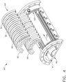
- the heat exchanger 40 has an inlet end or face 41, an outlet end or face 43 and a passageway 45 therebetween.
- the heat exchanger 40 is formed of a plurality of segments 50 which extend between an axially forward end 42 and an axially aft end 44. In addition to extending the segments 50 in an axial direction, the segments 50 are stacked on top of one another in a radial direction to increase the radial dimension of the heat exchanger 40.
- the heat exchanger 40 is formed of annular ring sections or segments which span a flow duct and allowing penetration flow area for heat exchange.
- the segments 50 laid in the radial direction provide for a cylindrical mesh which allows heat transfer as air flows through the heat exchanger 40.
- the heat exchanger of the embodiment shown is generally cylindrical however other shapes may be utilized to conform the heat exchanger to a duct wherein the exchanger 40 is positioned.
- the structure may be tapered in a radial direction across an axial length.
- other geometric shapes than the circular cross section depicted may be also utilized.
- the heat exchanger 40 may be curved to match a curved axis of a curved duct, as previously noted.
- the segment 50 includes a body 52 which extends circumferentially and has an axial length. Across the axial length are a plurality of flow paths or channels 54 which extend in a circumferential direction allowing flow of for example, oil needing cooling or alternatively, a cooling fluid utilized to reduce air temperature moving through the heat exchanger 40.
- the segment 50 also includes a plurality of fins 56 extending in a radial direction. The fins 56 are formed in a skiving process from a single piece of material which also defines the body 52. By skiving the fins 56, the process of brazing multiple fins to the body 52 is eliminated and therefore the costs for producing the segments 50 may be reduced.
- the body structure 52 is generally extruded and in a subsequent process the skiving step carves the fins 56 from the single piece of metal.
- the fins 56 may be carved in one or more directions, for example as shown in the axial and circumferential directions. Alternatively, the fins 56 may extend at some angle similar to a helical fin structure as well.
- fins 56 are shown extending radially from the body so as to extend outwardly therefrom the body 52. However, according to other embodiments fins 56 may be carved so as to extend either radially inward or both radially inward and outward.
- the body 52 includes a plurality of flow paths or channels for a fluid to be cooled or a fluid to cool the airflow.
- the axially forwardmost flow channel 54 alternatively according to one embodiment may be a blank. That is to say, the forwardmost flow path may not receive any fluid flow therein so as to preclude fluid leakage from foreign objects entering the heat exchanger 40, also referred to as foreign object damage.
- a leading edge 58 of the body 52 is curved to improve aerodynamics of the segment 50.
- the leading edge may have an increased material thickness to decrease damage from foreign object in the air flow path encountering the heat exchanger 40.
- the trailing edge may alternatively be curved.
- Various other shapes or arrangements may be utilized for a leading edge to improve overall aerodynamics of the entire assembly of the heat exchanger 40.
- FIGS. 6-8 the various figures depict alternate profiles that the heat exchanger 40 may have within the intercooler 30.
- a heat exchanger 40 is depicted with a rectangular profile when viewed in side section. This rectangular shape is created in part by the face shape at the forward end 42 of the exchanger 40, as well as the aft end of the exchanger. The forward end 42 may be varied as described in alternate embodiments.
- a forward end 142 of a heat exchanger 140 utilizes tapered forward face to form a polygon shaped profile. Such shape may be desirable to improve aerodynamics or alternatively limit damage from object within the flow stream.
- the heat exchanger 240 may include a leading profile 242 which is torus shaped. Again, this may be done for various reasons included but not limited to aerodynamics and limiting damage caused by material in the flow path.
- the heat exchanger 40 may be formed in various modular designs or shapes.
- a structure is shown with a split 60 extending radially through the exemplary heat exchanger 40 to allow the structure to be constructed in two modules 70 and connected together.
- alternate embodiments may be formed wherein multiple cut lines are utilized to form more modular shape without limiting function of the structure.
- the heat exchanger has four modular sections 170 defined by two linear splits 160-162 to define the quadrants.
- these embodiments may be formed in various shapes with various axial and/or angular lengths at the radially outer surface of the modules.
- the plant layout is shown in isometric view with a filter house 80 at the forward end of the process.
- the filter house takes in air through an inlet 82 and filters out some material for air is directed to a low pressure compressor and subsequently to the inner cooler 30.
- the structure of the heat exchanger may alternatively be used in the filter house according to an alternate embodiment.
- the body 52 is not curved circumferentially but may instead be flat or may be formed to provide various geometric shapes.
- the body may be supplied with a fluid to either cool the air if the power plant is in a high temperature and high humidity environment.
- a warming fluid may be utilized if the power plant is located in an extremely low temperature environment and the temperature of the incoming air needs to be raised.
- the heat exchanger may act as a preheater or a precooling portion within the filter house 80 at some position prior to the low pressure compressor step of power generation.
- water may be removed from the air entering the filter by natural condenation due to cooling of the air or further opational methods described further herein.
- the body structure of the segments may be used to provide heating fluid for preheating of air coming into the inlet 82.
- Other segments may be utilized for cooling fluid as previously described if the power plant is located in an extremely high temperature or high humidity environment.
- the totality of segments may be used for either heating or cooling.
- FIG. 11 an isometric view of one exemplary heat exchanger 40 is shown.
- a bifurcation 90 shown in broken line for clarity, is disposed at each of the splits 60 which define the modular portions of the heat exchanger 40.
- the bifurcations 90 inhibit airflow from passing over the structures joining the modules of the heat exchanger 40.
- the bifurcations 90 therefore inhibit pressure losses which would otherwise occur.
- the bifurcations 90 also have a second function in that the bifurcations 90 allow for thermal growth of the heat changer 40. From start up to normal operation, the heat exchanger 40 will grow radially 92 and axially 94. Additionally, the modules will increase in size circumferentially 96 so that the splits 60 or 160, 162 will increase in dimension.
- the bifurcation 90 compensates for, or accommodates, the thermal expansion of the heat exchanger 40 during operation.
- the bifurcation 90 depicted has an aerodynamic profile 98 to aid air flow movement structures joining the modules. Additionally, the bifurcation 90 will accept connections from fluid sources and/or house piping for such fluid wherein the fluid will pass through the heat exchanger 40.
- the view shows how fluid moves into the split 60 and then may move circumferentially through ducts or channels 54 of the segments 50 defining the modules.
- the fluid may make a single pass from one split to another.
- the fluid may also move across a split 60 by way of jumper tubing 91.
- the fluid may exit after an incomplete revolution, or may complete at least one or more full or partial revolutions about the heat exchanger before exiting through at one of the splits.
- the arcuate distance traveled by fluid through the heat exchanger 40 may vary based on the radius of the heat exchanger and the amount of cooling needed either for the fluid or for the air passing through the heat exchanger 40.
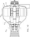
- FIGS. 12 and 13 side section views of the intercooler 30 are depicted including the heat exchanger 40.
- the flow path passing through the heat exchanger 40 engages a rear or aft wall 38 of the housing 36.
- the aft wall 38 has an interior surface including a water extraction apparatus 46 ( FIG. 12 ) which extends circumferentially about the axis of the intercooler 30.
- the apparatus 46 includes a baffle with a plurality of risers 48 extending generally perpendicular to the baffle.
- the baffle may be flat or may be curvilinear to match the contour of the rear wall 38.
- the risers 48 may be exposed at some angle other than 90 degrees to the baffle but in general create a plurality of channels 64.
- Heads 49 are located at ends of the risers 48 opposite the baffle and reduce the opening size of the channels 64. This aids in retaining water that is captured within the channels 64.
- An absorbant material may be positioned on inner surface of the channels 64 and/or along the outer surface of the heads 49 to retain water droplets and prevent them from being re-entrained in the airflow passing adjacent the water extraction device 46.
- the instant embodiment utilizes heads 49 that are generally parallel to the baffle such that the head 49 and the riser 48 create T-shaped cross-section. However, alternative shapes may be utilized such as, for example, a Y-shaped cross section or other designs. In any event the channel 64 is wider than a neck created between ends of the heads 49.
- the water extraction apparatus 46 is located along the rear surface 38 of the inner cooler 30 as depicted in FIG. 12 .
- air flow moves through the inner cooler and passes through the heat exchanger 40. After moving through the heat exchanger 40, the air flow turns rapidly and engages the extraction apparatus 46 located along the rear wall 38 of housing 36. The air flow changes direction rapidly due to change in the profile housing and shape of the housing 36. However, momentum of the water particles carries along the previously defined path so that the water particles are carried into the extraction device 46 and collected in the channels 64. The water drains through these channels 64 to a desired extraction point and may be collected or dumped as appropriate from the inner cooler 30. The collection or extraction point may be at the bottom of the extraction device 46 or the intercooler 30 so that gravity moves the collected water out of the system.
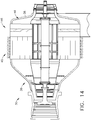
- an alternate embodiment is utilized wherein the water extraction device 146 is located between the heat exchanger 40 and the aft wall 38 of the housing 36.
- the extraction apparatus 146 sees air flow from the heat exchanger and engages the air flow capturing the water particles out of the air as previously described as the airflow is forced to turn. Channels defined by the apparatus 146 collect the water and move the water to a gathering location or discharge point where it is removed from the intercooler 30.
- multiple extraction devices 146 may be located between the heat exchanger 40 and the rear wall 38.
- a combination of the embodiment of FIGS. 12 and 14 may be utilized with one or more extraction apparatuses 146, located immediately after the heat exchanger 40 and additionally extraction devices are located along the rear wall 38.
- inventive embodiments are presented by way of example only and that, within the scope of the appended claims, inventive embodiments may be practiced otherwise than as specifically described.
- inventive embodiments of the present disclosure are directed to each individual feature, system, article, material, kit, and/or method described herein.
- any combination of two or more such features, systems, articles, materials, kits, and/or methods, if such features, systems, articles, materials, kits, and/or methods are not mutually inconsistent, is included within the inventive scope of the present disclosure.
Landscapes
- Engineering & Computer Science (AREA)
- Physics & Mathematics (AREA)
- Mechanical Engineering (AREA)
- General Engineering & Computer Science (AREA)
- Thermal Sciences (AREA)
- Chemical & Material Sciences (AREA)
- Combustion & Propulsion (AREA)
- Geometry (AREA)
- Heat-Exchange Devices With Radiators And Conduit Assemblies (AREA)
Claims (12)
- Wärmetauscherbaugruppe (40), Folgendes umfassend:eine axial vordere Fläche (41), eine axial hintere Fläche (43) und einen Durchgang (45), der sich von der vorderen Fläche zu der hinteren Fläche hin erstreckt, wobei mehrere Umfangssegmente (50) um den Durchgang herum zwischen der vorderen Fläche und der hinteren Fläche eingerichtet sind;wobei jedes der mehreren Segmente (50) aus einem einzigen Materialstück (52) ausgebildet ist, das innere Strömungswege (54) aufweist, die sich in einer Umfangsrichtung erstrecken;wobei jedes Segment mehrere Rippen (56) aufweist, die durch Abschälen des einzelnen Materialstücks (52) ausgebildet sind, wobei dadurch eine hartgelötete Verbindung der Rippen verhindert wird;wobei die mehreren Segmente Segmente umfassen, die in einer sich radial nach außen erstreckenden Anordnung gestapelt sind;wobei die mehreren Segmente Segmente umfassen, die angrenzend aneinander in einer axialen Anordnung eingerichtet sind;wobei die Strömungswege (54) der umlaufend angrenzenden Segmente in der Umfangsrichtung ausgerichtet sind.
- Baugruppe (40) nach Anspruch 1, wobei die Rippen (56) sich in eine radiale oder axiale Richtung erstrecken.
- Baugruppe (40) nach Anspruch 1, wobei die Rippen (56) sich radial nach innen und/oder radial nach außen erstrecken.
- Baugruppe (40) nach Anspruch 1, wobei ein axial vorderes Ende wenigstens eines axial vorderen Segments (50) eine aerodynamisch angepasste Vorderkante (58) aufweist.
- Baugruppe (40) nach Anspruch 1, wobei die vordere Fläche (41) eine geometrische Form aufweist.
- Baugruppe (40) nach Anspruch 5, wobei die vordere Fläche (41) konisch, gekrümmt oder flach ist.
- Baugruppe (40) nach Anspruch 1, ferner umfassend Verzweigungen, die eine Wärmeausdehnung in eine radiale oder axiale Richtung ermöglichen.
- Baugruppe (40) nach Anspruch 1, wobei die Baugruppe modular ist.
- Baugruppe (40) nach Anspruch 8, wobei die modulare Baugruppe in zwei Hälften geteilt ist.
- Baugruppe (40) nach Anspruch 8, wobei die modulare Baugruppe in Quadranten geteilt ist.
- Baugruppe (40) nach Anspruch 1, ferner umfassend eine Turbinenwelle, die sich durch den Durchgang (45) hindurch erstreckt.
- Turbinenmotor, umfassend die Baugruppe (40) nach Anspruch 1, wobei die Wärmetauscherbaugruppe innerhalb eines Kanals von einer Turbinenwelle versetzt positioniert ist.
Applications Claiming Priority (2)
| Application Number | Priority Date | Filing Date | Title |
|---|---|---|---|
| US13/561,627 US20140027097A1 (en) | 2012-07-30 | 2012-07-30 | Heat Exchanger for an Intercooler and Water Extraction Apparatus |
| PCT/US2013/048844 WO2014022046A2 (en) | 2012-07-30 | 2013-07-01 | Heat exchanger for an intercooler and water extraction apparatus |
Publications (2)
| Publication Number | Publication Date |
|---|---|
| EP2880284A2 EP2880284A2 (de) | 2015-06-10 |
| EP2880284B1 true EP2880284B1 (de) | 2019-12-11 |
Family
ID=48795925
Family Applications (1)
| Application Number | Title | Priority Date | Filing Date |
|---|---|---|---|
| EP13737933.5A Active EP2880284B1 (de) | 2012-07-30 | 2013-07-01 | Wärmetauscher für einen ladeluftkühler |
Country Status (7)
| Country | Link |
|---|---|
| US (1) | US20140027097A1 (de) |
| EP (1) | EP2880284B1 (de) |
| JP (1) | JP6074504B2 (de) |
| CN (1) | CN105164387B (de) |
| BR (1) | BR112015001975A2 (de) |
| CA (1) | CA2879390C (de) |
| WO (1) | WO2014022046A2 (de) |
Families Citing this family (6)
| Publication number | Priority date | Publication date | Assignee | Title |
|---|---|---|---|---|
| US8813503B2 (en) | 2012-06-14 | 2014-08-26 | General Electric Company | Gas turbine control systems and methods |
| JP6484845B2 (ja) * | 2013-06-25 | 2019-03-20 | 三菱重工コンプレッサ株式会社 | ガスタービンコンバインドサイクル設備、水上設備 |
| US20170211478A1 (en) * | 2014-04-11 | 2017-07-27 | Unison Industries, Llc | Tubular cooler with integrated fan |
| US20170191750A1 (en) * | 2015-12-31 | 2017-07-06 | General Electric Company | System and method for compressor intercooler |
| CN108007233A (zh) * | 2017-12-28 | 2018-05-08 | 无锡宏盛换热器制造股份有限公司 | 冷却器 |
| US20190277580A1 (en) * | 2018-03-07 | 2019-09-12 | United Technologies Corporation | Segmented fins for a cast heat exchanger |
Family Cites Families (30)
| Publication number | Priority date | Publication date | Assignee | Title |
|---|---|---|---|---|
| US1916399A (en) * | 1932-01-07 | 1933-07-04 | Sargent & Co | Door holder |
| US3477505A (en) * | 1967-07-13 | 1969-11-11 | Texaco Inc | Heat exchanger |
| US3746086A (en) * | 1971-08-27 | 1973-07-17 | Peerless Of America | Heat exchangers |
| DE2148079B2 (de) * | 1971-09-27 | 1976-11-04 | Regehr, Ulrich, Dr.-Ing., 5100 Aachen | Vorrichtung zum abscheiden von fluessigkeitstropfen |
| US3886639A (en) * | 1975-02-01 | 1975-06-03 | Peerless Of America | Method of making a finned heat exchanger |
| US4254618A (en) * | 1977-08-18 | 1981-03-10 | General Electric Company | Cooling air cooler for a gas turbofan engine |
| US4794985A (en) * | 1987-04-29 | 1989-01-03 | Peerless Of America Incorporated | Finned heat exchanger tubing with varying wall thickness |
| US4949544A (en) * | 1988-12-06 | 1990-08-21 | General Electric Company | Series intercooler |
| US5535584A (en) * | 1993-10-19 | 1996-07-16 | California Energy Commission | Performance enhanced gas turbine powerplants |
| WO1995011376A1 (en) * | 1993-10-19 | 1995-04-27 | State Of California Energy Resources Conservation And Development Commission | Performance enhanced gas turbine powerplants |
| US5669217A (en) * | 1995-09-25 | 1997-09-23 | Anderson; J. Hilbert | Method and apparatus for intercooling gas turbines |
| FR2766231B1 (fr) * | 1997-07-18 | 1999-08-20 | Snecma | Dispositif d'echauffement ou de refroidissement d'un carter circulaire |
| US6430931B1 (en) * | 1997-10-22 | 2002-08-13 | General Electric Company | Gas turbine in-line intercooler |
| US6134880A (en) * | 1997-12-31 | 2000-10-24 | Concepts Eti, Inc. | Turbine engine with intercooler in bypass air passage |
| US7278472B2 (en) * | 2002-09-20 | 2007-10-09 | Modine Manufacturing Company | Internally mounted radial flow intercooler for a combustion air changer |
| US6929056B2 (en) * | 2002-12-06 | 2005-08-16 | Modine Manufacturing Company | Tank manifold for internally mounted radial flow intercooler for a combustion air charger |
| US7272933B2 (en) * | 2004-01-28 | 2007-09-25 | General Electric Company | Methods and apparatus for operating gas turbine engines |
| BE1015880A3 (nl) * | 2004-02-03 | 2005-10-04 | Atlas Copco Airpower Nv | Warmtewisselaar. |
| US7377098B2 (en) * | 2004-08-26 | 2008-05-27 | United Technologies Corporation | Gas turbine engine frame with an integral fluid reservoir and air/fluid heat exchanger |
| US7963095B2 (en) * | 2006-06-21 | 2011-06-21 | General Electric Company | Inlet air conditioning system |
| US8387362B2 (en) * | 2006-10-19 | 2013-03-05 | Michael Ralph Storage | Method and apparatus for operating gas turbine engine heat exchangers |
| US7874156B2 (en) * | 2007-03-29 | 2011-01-25 | General Electric Company | Methods and apparatus for heating a fluid |
| CN101086434A (zh) * | 2007-05-22 | 2007-12-12 | 张广全 | 一种换热器及其制作方法 |
| US7946806B2 (en) * | 2007-10-10 | 2011-05-24 | United Technologies Corporation | Gas turbine engine systems and related methods involving heat exchange |
| EP2075194B1 (de) * | 2007-12-27 | 2017-08-16 | Techspace Aero | Luft-Öl-Wärmetauscher für ein Turbostrahltriebwerk, zugehöriges Turbostrahltriebwerk und Benutzung dieses Wärmetauschers |
| US20100043415A1 (en) * | 2008-08-12 | 2010-02-25 | Andreas Capelle | Extruded gas cooler |
| WO2010099535A2 (en) * | 2009-02-27 | 2010-09-02 | Purdue Research Foundation | Liquid-gas heat exchanger |
| CN102665884A (zh) * | 2009-09-10 | 2012-09-12 | 通用电气公司 | 用于组装蒸发冷却器的系统和方法 |
| EP2339123B1 (de) * | 2009-12-23 | 2013-07-10 | Techspace Aero S.A. | Innere Seite des Mantels des Sekundärstromes eines Turbostrahltriebwerkes und Verfahren zur Montage eines solchen Mantels |
| US9238284B2 (en) * | 2011-12-20 | 2016-01-19 | Unison Industries, Llc | Methods for forming a heat exchanger and portions thereof |
-
2012
- 2012-07-30 US US13/561,627 patent/US20140027097A1/en not_active Abandoned
-
2013
- 2013-07-01 JP JP2015525430A patent/JP6074504B2/ja not_active Expired - Fee Related
- 2013-07-01 CN CN201380040785.9A patent/CN105164387B/zh active Active
- 2013-07-01 BR BR112015001975A patent/BR112015001975A2/pt not_active Application Discontinuation
- 2013-07-01 EP EP13737933.5A patent/EP2880284B1/de active Active
- 2013-07-01 WO PCT/US2013/048844 patent/WO2014022046A2/en not_active Ceased
- 2013-07-01 CA CA2879390A patent/CA2879390C/en active Active
Non-Patent Citations (1)
| Title |
|---|
| None * |
Also Published As
| Publication number | Publication date |
|---|---|
| CN105164387B (zh) | 2017-05-10 |
| CN105164387A (zh) | 2015-12-16 |
| JP2015525868A (ja) | 2015-09-07 |
| CA2879390A1 (en) | 2014-02-06 |
| CA2879390C (en) | 2021-02-16 |
| EP2880284A2 (de) | 2015-06-10 |
| WO2014022046A2 (en) | 2014-02-06 |
| US20140027097A1 (en) | 2014-01-30 |
| BR112015001975A2 (pt) | 2017-07-04 |
| JP6074504B2 (ja) | 2017-02-01 |
| WO2014022046A3 (en) | 2014-03-20 |
Similar Documents
| Publication | Publication Date | Title |
|---|---|---|
| US12078426B2 (en) | Contoured wall heat exchanger | |
| US11421598B2 (en) | Staggered heat exchanger array with side curtains | |
| EP2880284B1 (de) | Wärmetauscher für einen ladeluftkühler | |
| US9777963B2 (en) | Method and system for radial tubular heat exchangers | |
| US10422585B2 (en) | Heat exchanger with interspersed arrangement of cross-flow structures | |
| US20170122210A1 (en) | Heat exchange module for a turbine engine | |
| US11090600B2 (en) | Particle separator assembly for a turbine engine | |
| US20170211478A1 (en) | Tubular cooler with integrated fan | |
| US12345200B2 (en) | Particle separators for turbomachines and method of operating the same | |
| US20170191750A1 (en) | System and method for compressor intercooler |
Legal Events
| Date | Code | Title | Description |
|---|---|---|---|
| PUAI | Public reference made under article 153(3) epc to a published international application that has entered the european phase |
Free format text: ORIGINAL CODE: 0009012 |
|
| 17P | Request for examination filed |
Effective date: 20150302 |
|
| AK | Designated contracting states |
Kind code of ref document: A2 Designated state(s): AL AT BE BG CH CY CZ DE DK EE ES FI FR GB GR HR HU IE IS IT LI LT LU LV MC MK MT NL NO PL PT RO RS SE SI SK SM TR |
|
| AX | Request for extension of the european patent |
Extension state: BA ME |
|
| DAX | Request for extension of the european patent (deleted) | ||
| STAA | Information on the status of an ep patent application or granted ep patent |
Free format text: STATUS: EXAMINATION IS IN PROGRESS |
|
| 17Q | First examination report despatched |
Effective date: 20180716 |
|
| GRAP | Despatch of communication of intention to grant a patent |
Free format text: ORIGINAL CODE: EPIDOSNIGR1 |
|
| STAA | Information on the status of an ep patent application or granted ep patent |
Free format text: STATUS: GRANT OF PATENT IS INTENDED |
|
| INTG | Intention to grant announced |
Effective date: 20190712 |
|
| GRAS | Grant fee paid |
Free format text: ORIGINAL CODE: EPIDOSNIGR3 |
|
| GRAA | (expected) grant |
Free format text: ORIGINAL CODE: 0009210 |
|
| STAA | Information on the status of an ep patent application or granted ep patent |
Free format text: STATUS: THE PATENT HAS BEEN GRANTED |
|
| AK | Designated contracting states |
Kind code of ref document: B1 Designated state(s): AL AT BE BG CH CY CZ DE DK EE ES FI FR GB GR HR HU IE IS IT LI LT LU LV MC MK MT NL NO PL PT RO RS SE SI SK SM TR |
|
| REG | Reference to a national code |
Ref country code: GB Ref legal event code: FG4D |
|
| REG | Reference to a national code |
Ref country code: CH Ref legal event code: EP |
|
| REG | Reference to a national code |
Ref country code: AT Ref legal event code: REF Ref document number: 1212414 Country of ref document: AT Kind code of ref document: T Effective date: 20191215 |
|
| REG | Reference to a national code |
Ref country code: DE Ref legal event code: R096 Ref document number: 602013063874 Country of ref document: DE |
|
| REG | Reference to a national code |
Ref country code: IE Ref legal event code: FG4D |
|
| REG | Reference to a national code |
Ref country code: NL Ref legal event code: MP Effective date: 20191211 |
|
| REG | Reference to a national code |
Ref country code: LT Ref legal event code: MG4D |
|
| PG25 | Lapsed in a contracting state [announced via postgrant information from national office to epo] |
Ref country code: ES Free format text: LAPSE BECAUSE OF FAILURE TO SUBMIT A TRANSLATION OF THE DESCRIPTION OR TO PAY THE FEE WITHIN THE PRESCRIBED TIME-LIMIT Effective date: 20191211 Ref country code: LT Free format text: LAPSE BECAUSE OF FAILURE TO SUBMIT A TRANSLATION OF THE DESCRIPTION OR TO PAY THE FEE WITHIN THE PRESCRIBED TIME-LIMIT Effective date: 20191211 Ref country code: FI Free format text: LAPSE BECAUSE OF FAILURE TO SUBMIT A TRANSLATION OF THE DESCRIPTION OR TO PAY THE FEE WITHIN THE PRESCRIBED TIME-LIMIT Effective date: 20191211 Ref country code: NO Free format text: LAPSE BECAUSE OF FAILURE TO SUBMIT A TRANSLATION OF THE DESCRIPTION OR TO PAY THE FEE WITHIN THE PRESCRIBED TIME-LIMIT Effective date: 20200311 Ref country code: BG Free format text: LAPSE BECAUSE OF FAILURE TO SUBMIT A TRANSLATION OF THE DESCRIPTION OR TO PAY THE FEE WITHIN THE PRESCRIBED TIME-LIMIT Effective date: 20200311 Ref country code: GR Free format text: LAPSE BECAUSE OF FAILURE TO SUBMIT A TRANSLATION OF THE DESCRIPTION OR TO PAY THE FEE WITHIN THE PRESCRIBED TIME-LIMIT Effective date: 20200312 Ref country code: LV Free format text: LAPSE BECAUSE OF FAILURE TO SUBMIT A TRANSLATION OF THE DESCRIPTION OR TO PAY THE FEE WITHIN THE PRESCRIBED TIME-LIMIT Effective date: 20191211 Ref country code: SE Free format text: LAPSE BECAUSE OF FAILURE TO SUBMIT A TRANSLATION OF THE DESCRIPTION OR TO PAY THE FEE WITHIN THE PRESCRIBED TIME-LIMIT Effective date: 20191211 |
|
| PG25 | Lapsed in a contracting state [announced via postgrant information from national office to epo] |
Ref country code: HR Free format text: LAPSE BECAUSE OF FAILURE TO SUBMIT A TRANSLATION OF THE DESCRIPTION OR TO PAY THE FEE WITHIN THE PRESCRIBED TIME-LIMIT Effective date: 20191211 Ref country code: RS Free format text: LAPSE BECAUSE OF FAILURE TO SUBMIT A TRANSLATION OF THE DESCRIPTION OR TO PAY THE FEE WITHIN THE PRESCRIBED TIME-LIMIT Effective date: 20191211 |
|
| PG25 | Lapsed in a contracting state [announced via postgrant information from national office to epo] |
Ref country code: AL Free format text: LAPSE BECAUSE OF FAILURE TO SUBMIT A TRANSLATION OF THE DESCRIPTION OR TO PAY THE FEE WITHIN THE PRESCRIBED TIME-LIMIT Effective date: 20191211 |
|
| PG25 | Lapsed in a contracting state [announced via postgrant information from national office to epo] |
Ref country code: RO Free format text: LAPSE BECAUSE OF FAILURE TO SUBMIT A TRANSLATION OF THE DESCRIPTION OR TO PAY THE FEE WITHIN THE PRESCRIBED TIME-LIMIT Effective date: 20191211 Ref country code: CZ Free format text: LAPSE BECAUSE OF FAILURE TO SUBMIT A TRANSLATION OF THE DESCRIPTION OR TO PAY THE FEE WITHIN THE PRESCRIBED TIME-LIMIT Effective date: 20191211 Ref country code: PT Free format text: LAPSE BECAUSE OF FAILURE TO SUBMIT A TRANSLATION OF THE DESCRIPTION OR TO PAY THE FEE WITHIN THE PRESCRIBED TIME-LIMIT Effective date: 20200506 Ref country code: NL Free format text: LAPSE BECAUSE OF FAILURE TO SUBMIT A TRANSLATION OF THE DESCRIPTION OR TO PAY THE FEE WITHIN THE PRESCRIBED TIME-LIMIT Effective date: 20191211 Ref country code: EE Free format text: LAPSE BECAUSE OF FAILURE TO SUBMIT A TRANSLATION OF THE DESCRIPTION OR TO PAY THE FEE WITHIN THE PRESCRIBED TIME-LIMIT Effective date: 20191211 |
|
| PG25 | Lapsed in a contracting state [announced via postgrant information from national office to epo] |
Ref country code: SK Free format text: LAPSE BECAUSE OF FAILURE TO SUBMIT A TRANSLATION OF THE DESCRIPTION OR TO PAY THE FEE WITHIN THE PRESCRIBED TIME-LIMIT Effective date: 20191211 Ref country code: IS Free format text: LAPSE BECAUSE OF FAILURE TO SUBMIT A TRANSLATION OF THE DESCRIPTION OR TO PAY THE FEE WITHIN THE PRESCRIBED TIME-LIMIT Effective date: 20200411 Ref country code: SM Free format text: LAPSE BECAUSE OF FAILURE TO SUBMIT A TRANSLATION OF THE DESCRIPTION OR TO PAY THE FEE WITHIN THE PRESCRIBED TIME-LIMIT Effective date: 20191211 |
|
| REG | Reference to a national code |
Ref country code: DE Ref legal event code: R097 Ref document number: 602013063874 Country of ref document: DE |
|
| REG | Reference to a national code |
Ref country code: AT Ref legal event code: MK05 Ref document number: 1212414 Country of ref document: AT Kind code of ref document: T Effective date: 20191211 |
|
| PLBE | No opposition filed within time limit |
Free format text: ORIGINAL CODE: 0009261 |
|
| STAA | Information on the status of an ep patent application or granted ep patent |
Free format text: STATUS: NO OPPOSITION FILED WITHIN TIME LIMIT |
|
| PG25 | Lapsed in a contracting state [announced via postgrant information from national office to epo] |
Ref country code: DK Free format text: LAPSE BECAUSE OF FAILURE TO SUBMIT A TRANSLATION OF THE DESCRIPTION OR TO PAY THE FEE WITHIN THE PRESCRIBED TIME-LIMIT Effective date: 20191211 |
|
| 26N | No opposition filed |
Effective date: 20200914 |
|
| PG25 | Lapsed in a contracting state [announced via postgrant information from national office to epo] |
Ref country code: SI Free format text: LAPSE BECAUSE OF FAILURE TO SUBMIT A TRANSLATION OF THE DESCRIPTION OR TO PAY THE FEE WITHIN THE PRESCRIBED TIME-LIMIT Effective date: 20191211 Ref country code: PL Free format text: LAPSE BECAUSE OF FAILURE TO SUBMIT A TRANSLATION OF THE DESCRIPTION OR TO PAY THE FEE WITHIN THE PRESCRIBED TIME-LIMIT Effective date: 20191211 Ref country code: AT Free format text: LAPSE BECAUSE OF FAILURE TO SUBMIT A TRANSLATION OF THE DESCRIPTION OR TO PAY THE FEE WITHIN THE PRESCRIBED TIME-LIMIT Effective date: 20191211 |
|
| PG25 | Lapsed in a contracting state [announced via postgrant information from national office to epo] |
Ref country code: IT Free format text: LAPSE BECAUSE OF FAILURE TO SUBMIT A TRANSLATION OF THE DESCRIPTION OR TO PAY THE FEE WITHIN THE PRESCRIBED TIME-LIMIT Effective date: 20191211 |
|
| REG | Reference to a national code |
Ref country code: DE Ref legal event code: R119 Ref document number: 602013063874 Country of ref document: DE |
|
| PG25 | Lapsed in a contracting state [announced via postgrant information from national office to epo] |
Ref country code: MC Free format text: LAPSE BECAUSE OF FAILURE TO SUBMIT A TRANSLATION OF THE DESCRIPTION OR TO PAY THE FEE WITHIN THE PRESCRIBED TIME-LIMIT Effective date: 20191211 |
|
| REG | Reference to a national code |
Ref country code: CH Ref legal event code: PL |
|
| GBPC | Gb: european patent ceased through non-payment of renewal fee |
Effective date: 20200701 |
|
| REG | Reference to a national code |
Ref country code: BE Ref legal event code: MM Effective date: 20200731 |
|
| PG25 | Lapsed in a contracting state [announced via postgrant information from national office to epo] |
Ref country code: IE Free format text: LAPSE BECAUSE OF NON-PAYMENT OF DUE FEES Effective date: 20200701 Ref country code: GB Free format text: LAPSE BECAUSE OF NON-PAYMENT OF DUE FEES Effective date: 20200701 Ref country code: LI Free format text: LAPSE BECAUSE OF NON-PAYMENT OF DUE FEES Effective date: 20200731 Ref country code: CH Free format text: LAPSE BECAUSE OF NON-PAYMENT OF DUE FEES Effective date: 20200731 Ref country code: FR Free format text: LAPSE BECAUSE OF NON-PAYMENT OF DUE FEES Effective date: 20200731 Ref country code: LU Free format text: LAPSE BECAUSE OF NON-PAYMENT OF DUE FEES Effective date: 20200701 |
|
| PG25 | Lapsed in a contracting state [announced via postgrant information from national office to epo] |
Ref country code: BE Free format text: LAPSE BECAUSE OF NON-PAYMENT OF DUE FEES Effective date: 20200731 Ref country code: DE Free format text: LAPSE BECAUSE OF NON-PAYMENT OF DUE FEES Effective date: 20210202 |
|
| PG25 | Lapsed in a contracting state [announced via postgrant information from national office to epo] |
Ref country code: TR Free format text: LAPSE BECAUSE OF FAILURE TO SUBMIT A TRANSLATION OF THE DESCRIPTION OR TO PAY THE FEE WITHIN THE PRESCRIBED TIME-LIMIT Effective date: 20191211 Ref country code: MT Free format text: LAPSE BECAUSE OF FAILURE TO SUBMIT A TRANSLATION OF THE DESCRIPTION OR TO PAY THE FEE WITHIN THE PRESCRIBED TIME-LIMIT Effective date: 20191211 Ref country code: CY Free format text: LAPSE BECAUSE OF FAILURE TO SUBMIT A TRANSLATION OF THE DESCRIPTION OR TO PAY THE FEE WITHIN THE PRESCRIBED TIME-LIMIT Effective date: 20191211 |
|
| PG25 | Lapsed in a contracting state [announced via postgrant information from national office to epo] |
Ref country code: MK Free format text: LAPSE BECAUSE OF FAILURE TO SUBMIT A TRANSLATION OF THE DESCRIPTION OR TO PAY THE FEE WITHIN THE PRESCRIBED TIME-LIMIT Effective date: 20191211 |