EP2879923B1 - Dispositif de montage d'une pedale d'un vehicule automobile - Google Patents
Dispositif de montage d'une pedale d'un vehicule automobile Download PDFInfo
- Publication number
- EP2879923B1 EP2879923B1 EP13731841.6A EP13731841A EP2879923B1 EP 2879923 B1 EP2879923 B1 EP 2879923B1 EP 13731841 A EP13731841 A EP 13731841A EP 2879923 B1 EP2879923 B1 EP 2879923B1
- Authority
- EP
- European Patent Office
- Prior art keywords
- pedal
- support
- shaft
- vehicle
- principal
- Prior art date
- Legal status (The legal status is an assumption and is not a legal conclusion. Google has not performed a legal analysis and makes no representation as to the accuracy of the status listed.)
- Not-in-force
Links
- 238000010008 shearing Methods 0.000 claims description 11
- 238000006073 displacement reaction Methods 0.000 claims description 7
- 229910000831 Steel Inorganic materials 0.000 claims description 3
- 229920003023 plastic Polymers 0.000 claims description 3
- 239000004033 plastic Substances 0.000 claims description 3
- 239000010959 steel Substances 0.000 claims description 3
- 239000000463 material Substances 0.000 claims description 2
- 230000000903 blocking effect Effects 0.000 claims 2
- 230000005540 biological transmission Effects 0.000 description 9
- 230000008901 benefit Effects 0.000 description 3
- 230000006378 damage Effects 0.000 description 2
- 230000000694 effects Effects 0.000 description 2
- 230000035939 shock Effects 0.000 description 2
- 208000027418 Wounds and injury Diseases 0.000 description 1
- 230000003213 activating effect Effects 0.000 description 1
- 230000002950 deficient Effects 0.000 description 1
- 208000014674 injury Diseases 0.000 description 1
- 238000000034 method Methods 0.000 description 1
- 238000006467 substitution reaction Methods 0.000 description 1
Images

Classifications
-
- G—PHYSICS
- G05—CONTROLLING; REGULATING
- G05G—CONTROL DEVICES OR SYSTEMS INSOFAR AS CHARACTERISED BY MECHANICAL FEATURES ONLY
- G05G1/00—Controlling members, e.g. knobs or handles; Assemblies or arrangements thereof; Indicating position of controlling members
- G05G1/30—Controlling members actuated by foot
- G05G1/32—Controlling members actuated by foot with means to prevent injury
-
- B—PERFORMING OPERATIONS; TRANSPORTING
- B60—VEHICLES IN GENERAL
- B60R—VEHICLES, VEHICLE FITTINGS, OR VEHICLE PARTS, NOT OTHERWISE PROVIDED FOR
- B60R21/00—Arrangements or fittings on vehicles for protecting or preventing injuries to occupants or pedestrians in case of accidents or other traffic risks
- B60R21/02—Occupant safety arrangements or fittings, e.g. crash pads
- B60R21/09—Control elements or operating handles movable from an operative to an out-of-the way position, e.g. pedals, switch knobs, window cranks
-
- B—PERFORMING OPERATIONS; TRANSPORTING
- B60—VEHICLES IN GENERAL
- B60T—VEHICLE BRAKE CONTROL SYSTEMS OR PARTS THEREOF; BRAKE CONTROL SYSTEMS OR PARTS THEREOF, IN GENERAL; ARRANGEMENT OF BRAKING ELEMENTS ON VEHICLES IN GENERAL; PORTABLE DEVICES FOR PREVENTING UNWANTED MOVEMENT OF VEHICLES; VEHICLE MODIFICATIONS TO FACILITATE COOLING OF BRAKES
- B60T7/00—Brake-action initiating means
- B60T7/02—Brake-action initiating means for personal initiation
- B60T7/04—Brake-action initiating means for personal initiation foot actuated
- B60T7/06—Disposition of pedal
- B60T7/065—Disposition of pedal with means to prevent injuries in case of collision
-
- F—MECHANICAL ENGINEERING; LIGHTING; HEATING; WEAPONS; BLASTING
- F16—ENGINEERING ELEMENTS AND UNITS; GENERAL MEASURES FOR PRODUCING AND MAINTAINING EFFECTIVE FUNCTIONING OF MACHINES OR INSTALLATIONS; THERMAL INSULATION IN GENERAL
- F16D—COUPLINGS FOR TRANSMITTING ROTATION; CLUTCHES; BRAKES
- F16D9/00—Couplings with safety member for disconnecting, e.g. breaking or melting member
- F16D9/06—Couplings with safety member for disconnecting, e.g. breaking or melting member by breaking due to shear stress
-
- G—PHYSICS
- G05—CONTROLLING; REGULATING
- G05G—CONTROL DEVICES OR SYSTEMS INSOFAR AS CHARACTERISED BY MECHANICAL FEATURES ONLY
- G05G1/00—Controlling members, e.g. knobs or handles; Assemblies or arrangements thereof; Indicating position of controlling members
- G05G1/30—Controlling members actuated by foot
- G05G1/32—Controlling members actuated by foot with means to prevent injury
- G05G1/323—Controlling members actuated by foot with means to prevent injury means disconnecting the connection between pedal and controlled member, e.g. by breaking or bending the connecting rod
-
- G—PHYSICS
- G05—CONTROLLING; REGULATING
- G05G—CONTROL DEVICES OR SYSTEMS INSOFAR AS CHARACTERISED BY MECHANICAL FEATURES ONLY
- G05G1/00—Controlling members, e.g. knobs or handles; Assemblies or arrangements thereof; Indicating position of controlling members
- G05G1/30—Controlling members actuated by foot
- G05G1/32—Controlling members actuated by foot with means to prevent injury
- G05G1/327—Controlling members actuated by foot with means to prevent injury means disconnecting the pedal from its hinge or support, e.g. by breaking or bending the support
-
- G—PHYSICS
- G05—CONTROLLING; REGULATING
- G05G—CONTROL DEVICES OR SYSTEMS INSOFAR AS CHARACTERISED BY MECHANICAL FEATURES ONLY
- G05G1/00—Controlling members, e.g. knobs or handles; Assemblies or arrangements thereof; Indicating position of controlling members
- G05G1/30—Controlling members actuated by foot
- G05G1/44—Controlling members actuated by foot pivoting
-
- B—PERFORMING OPERATIONS; TRANSPORTING
- B60—VEHICLES IN GENERAL
- B60R—VEHICLES, VEHICLE FITTINGS, OR VEHICLE PARTS, NOT OTHERWISE PROVIDED FOR
- B60R21/00—Arrangements or fittings on vehicles for protecting or preventing injuries to occupants or pedestrians in case of accidents or other traffic risks
- B60R2021/0002—Type of accident
- B60R2021/0004—Frontal collision
-
- B—PERFORMING OPERATIONS; TRANSPORTING
- B60—VEHICLES IN GENERAL
- B60Y—INDEXING SCHEME RELATING TO ASPECTS CROSS-CUTTING VEHICLE TECHNOLOGY
- B60Y2400/00—Special features of vehicle units
- B60Y2400/81—Braking systems
-
- Y—GENERAL TAGGING OF NEW TECHNOLOGICAL DEVELOPMENTS; GENERAL TAGGING OF CROSS-SECTIONAL TECHNOLOGIES SPANNING OVER SEVERAL SECTIONS OF THE IPC; TECHNICAL SUBJECTS COVERED BY FORMER USPC CROSS-REFERENCE ART COLLECTIONS [XRACs] AND DIGESTS
- Y10—TECHNICAL SUBJECTS COVERED BY FORMER USPC
- Y10T—TECHNICAL SUBJECTS COVERED BY FORMER US CLASSIFICATION
- Y10T74/00—Machine element or mechanism
- Y10T74/20—Control lever and linkage systems
- Y10T74/20528—Foot operated
Definitions
- the invention relates to a device for mounting an actuation pedal on a vehicle.
- actuating pedals such as a brake pedal or a clutch pedal, located at the driver's feet, and emerging in a free space at the front of the seat driver.
- these pedals must be mounted in the vehicle in compliance with certain safety rules, especially with respect to the driver.
- the invention relates more particularly to a mounting device of an actuating pedal taking into account the safety of the driver, for example a frontal impact.
- EP0965506 which relates to a pedal mounting device, the principle of which consists in implementing a shearing device provided for separating the pedal from its support, in the case of a partial intrusion of the front block into the passenger compartment after a shock.
- the pedal is fixed to its support by means of an axis of rotation, and the shearing device is secured to a fixed element of the vehicle, to sever the two ends of the axis of the pedal, when said support penetrates into said passenger compartment under the effect of a collision.
- the accidental pedal stroke which is initially related to the moving support, is stopped very early, thus avoiding to come crashing, dangerous way, the driver's legs.
- the methods of mounting a pedal on a motor vehicle according to the invention are designed to allow the pedal, which would have been disengaged from its support, whether in normal driving situation or accidental situation, to keep at home. less partially, its functional integrity. In this way, a driver surprised at not being able to actuate normally the brake pedal or the clutch pedal, can always make up the situation, exerting a pressure of the foot on the pedal deficient, so as to obtain the desired function.
- the invention relates to a device for mounting a pedal of a vehicle, comprising a support on which is mounted the pedal via a main axis of rotation, shearing means connected to a body member fixed of said vehicle, said shearing means being able to radially shear said main axis in the case of a displacement of said support relative to said bodywork element, to separate said pedal from said support.
- the main characteristic of a mounting device according to the invention is that it comprises a secondary axis integral with the pedal and adapted to position the pedal, which has been sheared, in a new functional position.
- an actuating pedal comprises a lever arm, one end of which ends with a shoe materializing a bearing surface on which the driver will exert a thrust with his foot, and whose other end is secured to the main axis of rotation.
- said axis of rotation is sheared, it is the entire pedal which is released from its support, and which can move freely.
- the secondary axis will help to place the pedal, which has been sheared, in a secondary position, which will allow it, at least partially, to ensure its original function. It is assumed that the secondary functional position is different from the normal functional position.
- the pedal will be in a position close to the one it usually occupies, and will thus retain the ability to be operated by a simple pressure of the foot on the part of the driver, to ensure its initial function.
- the secondary axis can represent either a guide member that will allow to guide the displacement of the sheared pedal so that it is placed in a new functional position, the new axis of rotation of said pedal that moved after shearing. It should be noted that the secondary axis can fulfill both the above two functions.
- the mounting devices according to the invention were initially developed for the brake pedals mounted on a motor vehicle, because an unforeseen failure of the braking system during a normal driving phase, can have dramatic consequences for people, then that a failure of the clutch may seem less severe.
- the secondary axis constitutes the new axis of rotation of the pedal in its new functional position. Indeed, once the pedal has been sheared, the main axis of rotation has become inoperative. However, since the pedal was initially designed to operate by rotation, it was necessary to find a rotation axis by substitution through this secondary axis of rotation.
- the secondary axis is parallel to the main axis, when the pedal is articulated on the support. Since the pedal, which has been sheared, can be pivoted about its secondary axis, and since its accidental displacement as a result of shearing takes place in a longitudinal plane of the vehicle, it is essential that said pedal retain the same direction of rotation. to continue to perform its original function.
- the main axis joins two parallel and vertical walls of the support, each of said walls comprising an opening and the secondary axis projecting in each of said openings.
- the secondary axis emerges in each of said openings, and that the movement allowing the pedal to reach its new operating position, is notably made possible through these openings, which do not hinder the displacement of the secondary axis.
- These openings may be either similar to guide slots that will allow the oriented sliding of the secondary axis, or extended so as not to hinder the movement of the pedal in any direction.
- each wall extends in a longitudinal direction of the vehicle, the main axis and the secondary axis extending in a transverse direction of said vehicle.
- the two axes are perpendicular to the two walls, the displacement of the sheared pedal being effected parallel to said walls, between them.
- the openings of the walls which are identical and face each other in a transverse direction of the vehicle. This configuration prevents the pedal from being in an off-axis position, and therefore not very operational.
- each opening has a locking end for receiving the secondary axis, once the main axis has been sheared.
- the secondary axis moves in each opening, to come to lock at a tapered end of said openings. This end will contribute to freeze the new functional position of the sheared pedal.
- the secondary axis is located behind the main axis when the pedal is mounted on the support, the locking end of each opening being located behind said openings.
- the main axis is made of plastic and the secondary axis is made of steel.
- the secondary axis must be strong and resistant, and offer no possibility of being broken by external solicitation, as it constitutes a last resort security.
- the object of the invention is a pedal intended to be mounted on a motor vehicle support by means of a mounting device according to the invention.
- the main characteristic of a pedal according to the invention is that it comprises a secondary axis. Indeed, since the secondary axis is fixed irremovably to the pedal, it is an integral part of said pedal. This secondary axis may either constitute a patch relative to the pedal, or constitute with said pedal a single piece, made in a single operation.
- the mounting devices of a pedal according to the invention have the advantage of increasing the safety of the occupants of a vehicle, allowing the driver to leave a residual pedal actuation stroke, once it has been disconnected from its support, following an impact or in a normal driving situation. Despite this additional functionality, these devices have the advantage of maintaining a constant size compared to existing devices. Finally, the simplicity of the operating mechanism of the pedal which has been sheared, gives the mounting devices according to the invention, a character of great safety and high reliability.
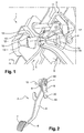
- a mounting device 1 of a brake pedal 2 comprises a support 3 on which is mounted said pedal 2 brake via a main axis of rotation 4, and shearing means secured to a fixed body element.
- the shearing means which may for example be similar to those described in the patent EP0965506 , comprise two knives each consisting of two cutting branches arranged in V.
- the pedal 2 is conventionally constituted by an elongated lever arm 5, a first end 6 of which terminates in a rough pad 7, materializing the bearing surface on which a driver will exert pressure with the foot to trigger the braking of the vehicle, and a second end 8 is hingedly connected to the support 3, through the main axis of rotation 4.
- Said lug 9 is flat and thin, and extends along a longitudinal axis of the lever arm 5, a first end 18 of said lug 9 being traversed by the axis main rotation 4, and a second end 19 being connected to said rigid transmission elements.
- FIG. 1 on which appears the location in which is positioned the main axis of rotation 4, said location being by assimilation also designated by the reference 4, said main axis of rotation 4 is fixed to two walls 10,11 parallel and vertical support 3, said walls 10,11 extending in a longitudinal direction of the vehicle.
- the second end 8 of the lever arm 5 carries a secondary axis 12, preferably of steel, and which is rigidly fixed to said lever arm 5.
- Each of the two walls 10,11 of the support 3, carrying the main axis of rotation 4 has an opening 13,14 having approximately a triangular shape. These two openings 13,14 are identical and are perfectly aligned with one another in a transverse direction of the vehicle.
- Each of said apertures 13, 14 has a tapered rear end 15 of rounded shape and whose dimensions are slightly greater than the diameter of the secondary axis 12.
- the secondary axis 12 is found parallel to the main axis of rotation 4, and protrudes at its two ends 16,17 in each of the two openings 13,14, at the front part of said openings 13,14.
- the secondary axis 12 is substantially at the same height as the main axis of rotation 4, and behind it.
- the interface lug 9 is also traversed by the secondary axis 12, in the vicinity of its first end 18.
- the secondary axis 12 ends up wedging in the two rear and rounded ends 15 of the openings 13,14 of the two walls 10,11 of the support 3.
- said pedal 2 continues to pivot, but around the secondary axis 12, which is locked in translation at the bottom of the rear ends 15 of the two openings 13,14.
- An extension of the rotation about this secondary axis 12, then causes a thrust on the rigid transmission elements, which eventually move and activate the braking system.
Landscapes
- Engineering & Computer Science (AREA)
- Mechanical Engineering (AREA)
- Physics & Mathematics (AREA)
- General Physics & Mathematics (AREA)
- Automation & Control Theory (AREA)
- Transportation (AREA)
- General Engineering & Computer Science (AREA)
- Mechanical Control Devices (AREA)
- Braking Elements And Transmission Devices (AREA)
Description
- L'invention se rapporte à un dispositif de montage d'une pédale d'actionnement sur un véhicule. Généralement un véhicule automobile conventionnel est doté de différentes pédales d'actionnement, comme par exemple, une pédale de frein ou une pédale d'embrayage, situées au niveau des pieds du conducteur, et émergeant dans un espace libre placé à l'avant du siège conducteur. Outre le fait d'accomplir avec rigueur et précision leur fonction, ces pédales doivent être montées dans le véhicule en respectant certaines règles de sécurité, notamment vis-à-vis du conducteur. L'invention se rapporte plus spécialement à un dispositif de montage d'une pédale d'actionnement tenant compte de la sécurité du conducteur, lors par exemple d'un choc frontal.
- Les dispositifs de montage d'une pédale d'actionnement dans un véhicule automobile existent et ont déjà fait l'objet de brevets. On peut par exemple citer le brevet
EP0965506 , qui se rapporte à un dispositif de montage d'une pédale, dont le principe consiste à mettre en oeuvre un dispositif de cisaillage prévu pour désolidariser la pédale de son support, dans le cas d'une intrusion partielle du bloc avant dans l'habitacle, suite à un choc. En effet, la pédale est fixée à son support par l'intermédiaire d'un axe de rotation, et le dispositif de cisaillage est arrimé à un élément fixe du véhicule, pour sectionner les deux extrémités de l'axe de la pédale, lorsque ledit support pénètre dans ledit habitacle sous l'effet d'une collision. Par ce biais, la course accidentelle de la pédale, qui est initialement liée au support en mouvement, est stoppée très tôt, évitant ainsi de venir percuter, de façon dangereuse, les jambes du conducteur. - Toutefois, avec ce type de dispositif de montage, il existe un risque non négligeable de voir le dispositif de cisaillage se déclencher intempestivement, sans raison apparente, alors que le véhicule est dans une phase de roulage normale, sans être soumis à un choc particulier. La pédale se décrocherait alors de son support, sans que le conducteur ne puisse bénéficier de la fonction habituelle de ladite pédale, comme par exemple, un freinage ou un débrayage. Même si les probabilités de voir un tel phénomène se produire demeurent minimes, les conséquences qu'il engendrerait, pourraient s'avérer très graves en matière de dommages corporels et/ou matériels. Il devient alors nécessaire de sécuriser les dispositifs de montage de pédale existants, afin d'éviter que de tels phénomènes potentiellement dangereux, ne se produisent.
- Les procédés de montage d'une pédale sur un véhicule automobile selon l'invention, sont conçus pour permettre à la pédale, qui se serait ainsi désolidarisée de son support, que ce soit en situation de roulage normal ou en situation accidentelle, de conserver au moins partiellement, son intégrité fonctionnelle. De cette manière, un conducteur surpris de ne pas pouvoir actionner normalement la pédale de frein ou la pédale d'embrayage, pourra toujours rattraper la situation, en exerçant une pression du pied sur la pédale déficiente, de façon à obtenir la fonction voulue.
- L'invention se rapporte à un dispositif de montage d'une pédale d'un véhicule, comprenant un support sur lequel est montée la pédale par l'intermédiaire d'un axe de rotation principal, des moyens de cisaillage reliés à un élément de carrosserie fixe dudit véhicule, lesdits moyens de cisaillages étant aptes à cisailler radialement ledit axe principal dans le cas d'un déplacement dudit support par rapport audit élément de carrosserie, pour désolidariser ladite pédale dudit support. La principale caractéristique d'un dispositif de montage selon l'invention est qu'il comprend un axe secondaire solidaire de la pédale et apte à positionner la pédale, qui a été cisaillée, dans une position fonctionnelle nouvelle. Il est important de rappeler qu'une pédale d'actionnement comprend un bras de levier, dont une extrémité se termine par un patin matérialisant une surface d'appui sur laquelle le conducteur va exercer une poussée avec son pied, et dont l'autre extrémité est solidarisée à l'axe de rotation principal. Ainsi, lorsque ledit axe de rotation est cisaillé, c'est l'ensemble de la pédale qui est libéré de son support, et qui peut donc se déplacer librement. L'axe secondaire va contribuer à placer la pédale, qui a été cisaillée, dans une position secondaire, qui va lui permettre, au moins partiellement, d'assurer sa fonction originelle. Il est supposé que la position fonctionnelle secondaire est différente de la position fonctionnelle normale. En effet, la pédale va se retrouver dans une position voisine de celle qu'elle occupe habituellement, et va conserver ainsi la possibilité d'être actionnée par une simple pression du pied de la part du conducteur, pour assurer sa fonction initiale. De cette manière, l'axe secondaire peut représenter, soit à un organe de guidage qui va permettre d'orienter le déplacement de la pédale cisaillée afin que celle-ci se place dans une nouvelle position fonctionnelle, soit le nouvel axe de rotation de ladite pédale qui s'est déplacée suite à son cisaillage. Il est à noter que l'axe secondaire peut remplir à la fois les deux fonctions précédentes. Les dispositifs de montage selon l'invention ont été initialement développés pour les pédales de frein montées sur un véhicule automobile, car une défaillance imprévue du système de freinage lors d'une phase normale de roulage, peut avoir des conséquences dramatiques sur les personnes, alors qu'une défaillance de l'embrayage peut paraitre moins sévère.
- Avantageusement, l'axe secondaire constitue le nouvel axe de rotation de la pédale dans sa nouvelle position fonctionnelle. En effet, une fois que la pédale a été cisaillée, l'axe de rotation principal est devenu inopérant. Or, puisque la pédale a été initialement conçue pour fonctionner par rotation, il a fallu lui trouver un axe de rotation par substitution à travers cet axe de rotation secondaire.
- De façon préférentielle, l'axe secondaire est parallèle à l'axe principal, lorsque la pédale est montée articulée sur le support. Puisque la pédale, qui a été cisaillée peut être amenée à pivoter autour de son axe secondaire, et comme son déplacement accidentel suite à son cisaillage s'effectue dans un plan longitudinal du véhicule, il est fondamental que ladite pédale conserve la même direction de rotation, pour continuer d'assurer sa fonction initiale.
- Préférentiellement, l'axe principal joint deux parois parallèles et verticales du support, chacune desdites parois comprenant une ouverture et l'axe secondaire saillant dans chacune desdites ouvertures. Pour cette configuration, il est supposé que l'axe secondaire émerge dans chacune desdites ouvertures, et que le mouvement permettant à la pédale d'atteindre sa nouvelle position de fonctionnement, est notamment rendu possible par l'intermédiaire des ces ouvertures, qui n'entravent pas le déplacement de l'axe secondaire. Ces ouvertures peuvent être, soit assimilables à des fentes de guidages qui vont permettre le coulissement orienté de l'axe secondaire, soit étendues pour ne pas gêner le déplacement de la pédale dans une quelconque direction.
- De façon avantageuse, chaque paroi s'étend selon une direction longitudinale du véhicule, l'axe principal et l'axe secondaire s'étendant selon une direction transversale dudit véhicule. De cette manière, les deux axes sont perpendiculaires aux deux parois, le déplacement de la pédale cisaillée s'effectuant parallèlement auxdites parois, entre celles-ci.
- Avantageusement, les ouvertures des parois dont identiques et se font face selon une direction transversale du véhicule. Cette configuration évite à la pédale de se retrouver dans une position désaxée, et donc peu opérationnelle.
- De façon préférentielle, chaque ouverture comporte une extrémité de blocage destinée à recevoir l'axe secondaire, une fois que l'axe principal a été cisaillé. En effet, lorsqu'un conducteur actionne la pédale qui s'est cisaillée, l'axe secondaire se déplace dans chaque ouverture, pour venir se bloquer au niveau d'une extrémité effilée desdites ouvertures. Cette extrémité va contribuer à figer la nouvelle position fonctionnelle de la pédale cisaillée.
- Préférentiellement, l'axe secondaire est situé derrière l'axe principal lorsque la pédale est montée sur le support, l'extrémité de blocage de chaque ouverture étant située à l'arrière desdites ouvertures.
- De façon avantageuse, l'axe principal est en plastique et l'axe secondaire est en acier. En effet, lorsque le véhicule est confronté à un choc frontal, il est important que l'axe principal puisse être cisaillé facilement de façon à être instantanément désolidarisé du support. A l'inverse, l'axe secondaire doit être solide et résistant, et n'offrir aucune possibilité d'être rompu par une sollicitation extérieure, car il constitue un ultime recours sécuritaire.
- L'invention a pour deuxième objet une pédale destinée à être montée sur un support de véhicule automobile au moyen d'un dispositif de montage conforme à l'invention. La principale caractéristique d'une pédale selon l'invention, est qu'elle comprend un axe secondaire. En effet, puisque l'axe secondaire est fixé de façon inamovible à la pédale, il fait partie intégrante de ladite pédale. Cet axe secondaire peut, soit constituer une pièce rapportée par rapport à la pédale, soit constituer avec ladite pédale une seule et même pièce, fabriquée en une seule opération.
- Les dispositifs de montage d'une pédale selon l'invention, présentent l'avantage d'accroître la sécurité des occupants d'un véhicule, en permettant au conducteur de laisser une course résiduelle d'actionnement de la pédale, une fois qu'elle a été désolidarisée de son support, suite à un choc ou dans une situation normale de roulage. Malgré cette fonctionnalité supplémentaire, ces dispositifs ont l'avantage de conserver un encombrement constant par rapport aux dispositifs existants. Enfin, la simplicité du mécanisme de fonctionnement de la pédale qui a été cisaillée, confère aux dispositifs de montage selon l'invention, un caractère de grande sûreté et de grande fiabilité.
- On donne ci-après une description détaillée d'un mode de réalisation préféré d'un dispositif de montage d'une pédale selon l'invention, en se référant aux
figures 1 et3c . - La
figure 1 est une vue en perspective de la liaison articulée d'une pédale de frein sur un support selon un dispositif de montage selon l'invention, - La
figure 2 est une vue en perspective d'une pédale de frein selon l'invention, - La
figure 3a est une vue de coté de la liaison articulée de la pédale de frein sur un support, issue d'un dispositif de montage selon l'invention, lors d'une première étape de fonctionnement en mode dégradé, - La
figure 3b est une vue de coté de la liaison articulée de la pédale de frein sur un support, issue d'un dispositif de montage selon l'invention, lors d'une deuxième étape de fonctionnement en mode dégradé, - La
figure 3c est une vue de coté de la liaison articulée de la pédale de frein sur un support selon un dispositif de montage selon l'invention, lors d'une troisième étape de fonctionnement en mode dégradé, - En se référant aux
figures 1 et 2 , un dispositif de montage 1 d'une pédale 2 de frein selon l'invention, comprend un support 3 sur lequel est montée ladite pédale 2 de frein par l'intermédiaire d'un axe de rotation 4 principal, et des moyens de cisaillage solidarisés à un élément de carrosserie fixe. Les moyens de cisaillage, qui peuvent par exemple être analogues à ceux décrits dans le brevetEP0965506 , comprennent deux couteaux constitués chacun par deux branches coupantes disposées en V. En se référant à lafigure 2 , la pédale 2 est constituée conventionnellement par un bras de levier 5 allongé, dont une première extrémité 6 se termine par un patin 7 rugueux, matérialisant la surface d'appui sur laquelle un conducteur va exercer une pression avec le pied pour déclencher le freinage du véhicule, et dont une deuxième extrémité 8 est reliée de façon articulée au support 3, par l'intermédiaire de l'axe de rotation 4 principal. Une patte d'interface 9 fixée rigidement au bras de levier 5 de la pédale 2, au niveau de sa deuxième extrémité 8, est solidarisée à des éléments de transmission rigides, non visibles sur les figures, pour déplacer lesdits éléments sous l'effet de la rotation de la pédale 2, et actionner le système de freinage. Ladite patte 9 est plane et de faible épaisseur, et s'étend selon un axe longitudinal du bras de levier 5, une première extrémité 18 de la dite patte 9 étant traversée par l'axe de rotation principal 4, et une deuxième extrémité 19 étant reliée auxdits éléments de transmission rigides. - En se référant à la
figure 1 , sur laquelle apparaît l'emplacement dans lequel est positionné l'axe de rotation principal 4, ledit emplacement étant par assimilation également désigné par la référence 4, ledit axe de rotation principal 4 est fixée à deux parois 10,11 parallèles et verticales du support 3, lesdites parois 10,11 s'étendant selon une direction longitudinale du véhicule. Cet axe de rotation principal 4, qui est préférentiellement en plastique pour pouvoir être facilement cisaillé en cas de choc frontal, lors d'une intrusion dudit support 3, est perpendiculaire auxdites parois 10,11 et s'étend donc selon une direction transversale dudit véhicule. En fonctionnement normal, une pression du pied appliquée sur le patin 7 engendre une rotation de la pédale 2 autour de l'axe de rotation 4 principal, qui va provoquer le déplacement des éléments de transmission par l'intermédiaire de la patte d'interface 9, activant ainsi le système de freinage du véhicule. La deuxième extrémité 8 du bras de levier 5 porte un axe secondaire 12, préférentiellement en acier, et qui est rigidement fixé audit bras de levier 5. Chacune des deux parois 10,11 du support 3, portant l'axe de rotation principal 4, est dotée d'une ouverture 13,14 ayant approximativement une forme triangulaire. Ces deux ouvertures 13,14 sont identiques et sont parfaitement alignées l'une sur l'autre selon une direction transversale du véhicule. Chacune desdites ouvertures 13,14 dispose d'une extrémité arrière 15 effilée, de forme arrondie et dont les dimensions sont légèrement supérieures au diamètre de l'axe secondaire 12. En se référant à lafigure 1 , lorsque la pédale 2 est montée sur le support 3 entre les deux parois 10,11, l'axe secondaire 12 se retrouve parallèle à l'axe de rotation principal 4, et saille au niveau de ses deux extrémités 16,17 dans chacune des deux ouvertures 13,14, à la partie avant desdites ouvertures 13,14. L'axe secondaire 12 se retrouve sensiblement à la même hauteur que l'axe de rotation principal 4, et en arrière de celui-ci. En se référant auxfigures 1 et 2 , il est à noter que la patte d'interface 9 est également traversée par l'axe secondaire 12, au voisinage de sa première extrémité 18. - En se référant à la
figure 3a , lorsqu'un usager exerce une pression sur le patin 7 de la pédale 2 de frein, alors que l'axe de rotation 4 principal a été cisaillé de façon inopinée, ladite pédale 2 amorce une rotation autour du point de contact 20 entre la deuxième extrémité 19 de la patte d'interface 9 et les éléments de transmission rigides, puisque les deux extrémités 6,8 du bras de levier 5 sont momentanément libres de tout mouvement. Lors de cette phase préliminaire de rotation, la pédale 2 ne fait que pivoter, sans pouvoir déplacer les éléments de transmission et donc sans pouvoir activer le système de freinage. - En se référant à la
figure 3b , lorsque la rotation de la pédale 2 se poursuit, l'axe de rotation 12 secondaire accompagne le pivotement de la pédale 2 de laquelle il est rigidement solidaire, en se rapprochant de l'extrémité arrière arrondie 15 desdites ouvertures 13,14. Durant cette deuxième phase de rotation de la pédale 2, ladite pédale 2 ne fait que pivoter autour du point de contact 20 entre la deuxième extrémité 19 de la patte d'interface 9 et les éléments de transmission rigides, toujours sans pouvoir déplacer lesdits éléments de transmission rigides, et donc sans pouvoir déclencher le système de freinage. - En se référant à la
figure 3c , l'axe secondaire 12 finit par se caler dans les deux extrémités arrière et arrondies 15 des ouvertures 13,14 des deux parois 10,11 du support 3. En maintenant une pression sur le patin 7 de la pédale 2, ladite pédale 2 continue de pivoter, mais autour de l'axe secondaire 12, qui est bloqué en translation au fond des extrémités arrière 15 des deux ouvertures 13,14. Une prolongation de la rotation autour de cet axe secondaire 12, provoque alors une poussée sur les éléments de transmission rigides, qui finissent par se déplacer et par activer le système de freinage. - La rotation autour du point d'intersection entre la deuxième extrémité 19 de la patte d'interface 9 et les éléments de transmission, et pour laquelle lesdits éléments ne sont pas déplacés, correspond environ aux deux tiers de la course totale de ladite pédale 2, tandis que la rotation autour de l'axe secondaire 12 et pour laquelle le système de freinage est activé, correspond au tiers de ladite course totale.
Claims (10)
- Dispositif de montage d'une pédale (2) d'un véhicule, comprenant un support (3) sur lequel est montée la pédale (2) par l'intermédiaire d'un axe de rotation principal (4), des moyens de cisaillage reliés à un élément de carrosserie fixe dudit véhicule, lesdits moyens de cisaillages étant aptes à cisailler radialement ledit axe principal (4) dans le cas d'un déplacement dudit support (3) par rapport audit élément de carrosserie, pour désolidariser ladite pédale (2) dudit support (3), caractérisé en ce qu'il comprend un axe secondaire (12) solidaire de la pédale (2) et apte à positionner la pédale (2), qui a été cisaillée, dans une nouvelle position fonctionnelle.
- Dispositif selon la revendication 1, caractérisé en ce que l'axe secondaire (12) constitue le nouvel axe de rotation de la pédale (2) dans sa nouvelle position fonctionnelle.
- Dispositif selon l'une quelconque des revendications 1 ou 2, caractérisé en ce que l'axe secondaire (12) est parallèle à l'axe principal (4), lorsque la pédale (2) est montée articulée sur le support (3).
- Dispositif selon la revendication 3, caractérisée en ce que l'axe principal (4) joint deux parois (10,11) parallèles et verticales du support (3), et en ce que chacune desdites parois (10,11) comprend une ouverture (13,14), l'axe secondaire (12) saillant dans lesdites ouvertures (13,14).
- Dispositif selon la revendication 4, caractérisé en ce que chaque paroi (10,11) s'étend selon une direction longitudinale du véhicule, et en ce que l'axe principal (4) et l'axe secondaire (12) s'étendent selon une direction transversale dudit véhicule.
- Dispositif selon l'une quelconque des revendications 4 ou 5, caractérisé en ce que les ouvertures (13,14) des parois dont identiques et se font face selon une direction transversale du véhicule.
- Dispositif selon la revendication 6 caractérisé en ce que chaque ouverture (13,14) comporte une extrémité (15) de blocage destinée à recevoir l'axe secondaire (12), une fois que l'axe principale (4)a été cisaillé.
- Dispositif selon la revendication 7, caractérisé en ce que l'axe secondaire (12) est situé derrière l'axe principal (4) lorsque la pédale (2) est montée sur le support (3), et en ce que l'extrémité (15) de blocage de chaque ouverture (13,14) est située à l'arrière desdites ouvertures (13,14).
- Dispositif selon l'une quelconque des revendications 1 à 8, caractérisé en ce que l'axe principal (4) est en plastique et l'axe secondaire (12) est en acier.
- Pédale (2) destinée à être montée sur un support (3) de véhicule automobile au moyen d'un dispositif (1) de montage conforme à l'une quelconque des revendications 1 à 9, caractérisé en ce qu'elle comprend un axe secondaire (12).
Applications Claiming Priority (3)
| Application Number | Priority Date | Filing Date | Title |
|---|---|---|---|
| RO201210021 | 2012-08-01 | ||
| FR1257473A FR2994150B1 (fr) | 2012-08-01 | 2012-08-01 | Dispositif de montage d'une pedale d'un vehicule automobile |
| PCT/FR2013/051331 WO2014020248A1 (fr) | 2012-08-01 | 2013-06-10 | Dispositif de montage d'une pedale d'un vehicule automobile |
Publications (2)
| Publication Number | Publication Date |
|---|---|
| EP2879923A1 EP2879923A1 (fr) | 2015-06-10 |
| EP2879923B1 true EP2879923B1 (fr) | 2016-11-16 |
Family
ID=48699845
Family Applications (1)
| Application Number | Title | Priority Date | Filing Date |
|---|---|---|---|
| EP13731841.6A Not-in-force EP2879923B1 (fr) | 2012-08-01 | 2013-06-10 | Dispositif de montage d'une pedale d'un vehicule automobile |
Country Status (5)
| Country | Link |
|---|---|
| US (1) | US9541944B2 (fr) |
| EP (1) | EP2879923B1 (fr) |
| JP (1) | JP6141431B2 (fr) |
| KR (1) | KR102080349B1 (fr) |
| WO (1) | WO2014020248A1 (fr) |
Family Cites Families (7)
| Publication number | Priority date | Publication date | Assignee | Title |
|---|---|---|---|---|
| FR2780172B1 (fr) | 1998-06-17 | 2000-09-08 | Renault | Dispositif de montage d'une pedale d'un vehicule automobile |
| JP3892653B2 (ja) * | 2000-09-14 | 2007-03-14 | 株式会社エフテック | 自動車のブレーキペダル装置 |
| DE60113958T2 (de) * | 2000-09-14 | 2006-07-27 | Nissan Motor Co., Ltd., Yokohama | Kraftfahrzeugbremspedalanordnung |
| FR2838695B1 (fr) | 2002-04-18 | 2004-06-18 | Renault Sa | Dispositif de commande de freinage a commande electrique adapte au freinage d'urgence |
| JP2011037377A (ja) * | 2009-08-11 | 2011-02-24 | Yorozu Corp | 自動車のブレーキペダル装置 |
| FR2974554B1 (fr) | 2011-04-26 | 2013-06-07 | Renault Sa | Dispositif de montage d'une pedale d'un vehicule automobile |
| US8899130B2 (en) | 2011-06-28 | 2014-12-02 | Autoline Industries Indiana, Llc | Vehicle pedal system |
-
2013
- 2013-06-10 EP EP13731841.6A patent/EP2879923B1/fr not_active Not-in-force
- 2013-06-10 US US14/418,665 patent/US9541944B2/en active Active
- 2013-06-10 JP JP2015524821A patent/JP6141431B2/ja not_active Expired - Fee Related
- 2013-06-10 WO PCT/FR2013/051331 patent/WO2014020248A1/fr active Application Filing
- 2013-06-10 KR KR1020157003639A patent/KR102080349B1/ko active IP Right Grant
Non-Patent Citations (1)
| Title |
|---|
| None * |
Also Published As
| Publication number | Publication date |
|---|---|
| WO2014020248A1 (fr) | 2014-02-06 |
| JP6141431B2 (ja) | 2017-06-07 |
| EP2879923A1 (fr) | 2015-06-10 |
| US20150192948A1 (en) | 2015-07-09 |
| US9541944B2 (en) | 2017-01-10 |
| JP2016502687A (ja) | 2016-01-28 |
| KR20150038049A (ko) | 2015-04-08 |
| KR102080349B1 (ko) | 2020-04-08 |
Similar Documents
| Publication | Publication Date | Title |
|---|---|---|
| EP2701953B1 (fr) | Dispositif de montage d'une pedale d'un vehicule automobile | |
| EP2471702B1 (fr) | Bicyclette pliable | |
| FR2944115A1 (fr) | Pedale de vehicule automobile avec dispositif de mise en securite. | |
| EP1448415A1 (fr) | Dispositif de montage d une pedale sur un vehicule | |
| WO2011054673A1 (fr) | Dispositif antivol pour colonne de direction de véhicule à super condamnation assurée par bascule intermédiaire | |
| EP0965506B1 (fr) | Dispositif de montage d'une pédale d'un véhicule automobile | |
| EP2089302B1 (fr) | Sabot de calage d'une roue et installation de calage motorisee | |
| WO2018073526A1 (fr) | Volant pour véhicule automobile autonome. | |
| EP2851320A1 (fr) | Dispositif de cale d'immobilisation de véhicule | |
| EP2930130B1 (fr) | Dispositif de cale d'immobilisation de vehicule | |
| EP2879923B1 (fr) | Dispositif de montage d'une pedale d'un vehicule automobile | |
| FR3107713A1 (fr) | Feu de signalisation mobile de chantier | |
| FR2994150A1 (fr) | Dispositif de montage d'une pedale d'un vehicule automobile | |
| EP1243491B1 (fr) | Dispositif de montage d'une pédale dans un véhicule | |
| EP3233590B1 (fr) | Antivol pour une colonne de direction de véhicule automobile | |
| FR2831125A1 (fr) | Dispositif de montage d'une pedale dans un vehicule | |
| EP2388492B1 (fr) | Dispositif d'assistance à la pédale de débrayage d'un véhicule automobile | |
| EP3156271A1 (fr) | Dispositif anti-dévers à bras couplés par un manchon translatable, pour un train de véhicule automobile | |
| FR2889142A1 (fr) | Dispositif antivol permettant de commander le verrouillage d'une colonne de direction d'un vehicule automobile | |
| FR2929214A1 (fr) | Dispositif antivol pour arbre de direction de vehicule automobile | |
| EP2380797B1 (fr) | Colonne de direction avec mécanisme de réglage télescopique et/ou fonction d'absorption d'énergie par rétraction | |
| FR3130725A1 (fr) | Système de freinage ferroviaire et véhicule ferroviaire pourvu d’un tel système | |
| FR3081805A1 (fr) | Systeme de freinage automatique et securise d'un vehicule | |
| FR2974553A1 (fr) | Vehicule dote d'un equipement de securite destine a proteger les jambes du conducteur | |
| FR3008664A1 (fr) | Dispositif de montage d'une pedale dans un vehicule automobile |
Legal Events
| Date | Code | Title | Description |
|---|---|---|---|
| PUAI | Public reference made under article 153(3) epc to a published international application that has entered the european phase |
Free format text: ORIGINAL CODE: 0009012 |
|
| 17P | Request for examination filed |
Effective date: 20150112 |
|
| AK | Designated contracting states |
Kind code of ref document: A1 Designated state(s): AL AT BE BG CH CY CZ DE DK EE ES FI FR GB GR HR HU IE IS IT LI LT LU LV MC MK MT NL NO PL PT RO RS SE SI SK SM TR |
|
| AX | Request for extension of the european patent |
Extension state: BA ME |
|
| DAX | Request for extension of the european patent (deleted) | ||
| GRAP | Despatch of communication of intention to grant a patent |
Free format text: ORIGINAL CODE: EPIDOSNIGR1 |
|
| INTG | Intention to grant announced |
Effective date: 20160819 |
|
| GRAS | Grant fee paid |
Free format text: ORIGINAL CODE: EPIDOSNIGR3 |
|
| GRAA | (expected) grant |
Free format text: ORIGINAL CODE: 0009210 |
|
| AK | Designated contracting states |
Kind code of ref document: B1 Designated state(s): AL AT BE BG CH CY CZ DE DK EE ES FI FR GB GR HR HU IE IS IT LI LT LU LV MC MK MT NL NO PL PT RO RS SE SI SK SM TR |
|
| REG | Reference to a national code |
Ref country code: GB Ref legal event code: FG4D Free format text: NOT ENGLISH |
|
| REG | Reference to a national code |
Ref country code: CH Ref legal event code: EP |
|
| REG | Reference to a national code |
Ref country code: IE Ref legal event code: FG4D Free format text: LANGUAGE OF EP DOCUMENT: FRENCH |
|
| REG | Reference to a national code |
Ref country code: AT Ref legal event code: REF Ref document number: 845590 Country of ref document: AT Kind code of ref document: T Effective date: 20161215 |
|
| REG | Reference to a national code |
Ref country code: DE Ref legal event code: R096 Ref document number: 602013014109 Country of ref document: DE |
|
| PG25 | Lapsed in a contracting state [announced via postgrant information from national office to epo] |
Ref country code: LV Free format text: LAPSE BECAUSE OF FAILURE TO SUBMIT A TRANSLATION OF THE DESCRIPTION OR TO PAY THE FEE WITHIN THE PRESCRIBED TIME-LIMIT Effective date: 20161116 |
|
| REG | Reference to a national code |
Ref country code: NL Ref legal event code: MP Effective date: 20161116 |
|
| REG | Reference to a national code |
Ref country code: LT Ref legal event code: MG4D |
|
| REG | Reference to a national code |
Ref country code: AT Ref legal event code: MK05 Ref document number: 845590 Country of ref document: AT Kind code of ref document: T Effective date: 20161116 |
|
| PG25 | Lapsed in a contracting state [announced via postgrant information from national office to epo] |
Ref country code: LT Free format text: LAPSE BECAUSE OF FAILURE TO SUBMIT A TRANSLATION OF THE DESCRIPTION OR TO PAY THE FEE WITHIN THE PRESCRIBED TIME-LIMIT Effective date: 20161116 Ref country code: NL Free format text: LAPSE BECAUSE OF FAILURE TO SUBMIT A TRANSLATION OF THE DESCRIPTION OR TO PAY THE FEE WITHIN THE PRESCRIBED TIME-LIMIT Effective date: 20161116 Ref country code: SE Free format text: LAPSE BECAUSE OF FAILURE TO SUBMIT A TRANSLATION OF THE DESCRIPTION OR TO PAY THE FEE WITHIN THE PRESCRIBED TIME-LIMIT Effective date: 20161116 Ref country code: NO Free format text: LAPSE BECAUSE OF FAILURE TO SUBMIT A TRANSLATION OF THE DESCRIPTION OR TO PAY THE FEE WITHIN THE PRESCRIBED TIME-LIMIT Effective date: 20170216 Ref country code: GR Free format text: LAPSE BECAUSE OF FAILURE TO SUBMIT A TRANSLATION OF THE DESCRIPTION OR TO PAY THE FEE WITHIN THE PRESCRIBED TIME-LIMIT Effective date: 20170217 |
|
| PG25 | Lapsed in a contracting state [announced via postgrant information from national office to epo] |
Ref country code: PL Free format text: LAPSE BECAUSE OF FAILURE TO SUBMIT A TRANSLATION OF THE DESCRIPTION OR TO PAY THE FEE WITHIN THE PRESCRIBED TIME-LIMIT Effective date: 20161116 Ref country code: RS Free format text: LAPSE BECAUSE OF FAILURE TO SUBMIT A TRANSLATION OF THE DESCRIPTION OR TO PAY THE FEE WITHIN THE PRESCRIBED TIME-LIMIT Effective date: 20161116 Ref country code: AT Free format text: LAPSE BECAUSE OF FAILURE TO SUBMIT A TRANSLATION OF THE DESCRIPTION OR TO PAY THE FEE WITHIN THE PRESCRIBED TIME-LIMIT Effective date: 20161116 Ref country code: PT Free format text: LAPSE BECAUSE OF FAILURE TO SUBMIT A TRANSLATION OF THE DESCRIPTION OR TO PAY THE FEE WITHIN THE PRESCRIBED TIME-LIMIT Effective date: 20170316 Ref country code: FI Free format text: LAPSE BECAUSE OF FAILURE TO SUBMIT A TRANSLATION OF THE DESCRIPTION OR TO PAY THE FEE WITHIN THE PRESCRIBED TIME-LIMIT Effective date: 20161116 Ref country code: ES Free format text: LAPSE BECAUSE OF FAILURE TO SUBMIT A TRANSLATION OF THE DESCRIPTION OR TO PAY THE FEE WITHIN THE PRESCRIBED TIME-LIMIT Effective date: 20161116 Ref country code: HR Free format text: LAPSE BECAUSE OF FAILURE TO SUBMIT A TRANSLATION OF THE DESCRIPTION OR TO PAY THE FEE WITHIN THE PRESCRIBED TIME-LIMIT Effective date: 20161116 |
|
| REG | Reference to a national code |
Ref country code: FR Ref legal event code: PLFP Year of fee payment: 5 |
|
| PG25 | Lapsed in a contracting state [announced via postgrant information from national office to epo] |
Ref country code: DK Free format text: LAPSE BECAUSE OF FAILURE TO SUBMIT A TRANSLATION OF THE DESCRIPTION OR TO PAY THE FEE WITHIN THE PRESCRIBED TIME-LIMIT Effective date: 20161116 Ref country code: EE Free format text: LAPSE BECAUSE OF FAILURE TO SUBMIT A TRANSLATION OF THE DESCRIPTION OR TO PAY THE FEE WITHIN THE PRESCRIBED TIME-LIMIT Effective date: 20161116 Ref country code: SK Free format text: LAPSE BECAUSE OF FAILURE TO SUBMIT A TRANSLATION OF THE DESCRIPTION OR TO PAY THE FEE WITHIN THE PRESCRIBED TIME-LIMIT Effective date: 20161116 Ref country code: RO Free format text: LAPSE BECAUSE OF FAILURE TO SUBMIT A TRANSLATION OF THE DESCRIPTION OR TO PAY THE FEE WITHIN THE PRESCRIBED TIME-LIMIT Effective date: 20161116 Ref country code: CZ Free format text: LAPSE BECAUSE OF FAILURE TO SUBMIT A TRANSLATION OF THE DESCRIPTION OR TO PAY THE FEE WITHIN THE PRESCRIBED TIME-LIMIT Effective date: 20161116 |
|
| REG | Reference to a national code |
Ref country code: DE Ref legal event code: R097 Ref document number: 602013014109 Country of ref document: DE |
|
| PG25 | Lapsed in a contracting state [announced via postgrant information from national office to epo] |
Ref country code: IT Free format text: LAPSE BECAUSE OF FAILURE TO SUBMIT A TRANSLATION OF THE DESCRIPTION OR TO PAY THE FEE WITHIN THE PRESCRIBED TIME-LIMIT Effective date: 20161116 Ref country code: SM Free format text: LAPSE BECAUSE OF FAILURE TO SUBMIT A TRANSLATION OF THE DESCRIPTION OR TO PAY THE FEE WITHIN THE PRESCRIBED TIME-LIMIT Effective date: 20161116 Ref country code: BG Free format text: LAPSE BECAUSE OF FAILURE TO SUBMIT A TRANSLATION OF THE DESCRIPTION OR TO PAY THE FEE WITHIN THE PRESCRIBED TIME-LIMIT Effective date: 20170216 |
|
| PLBE | No opposition filed within time limit |
Free format text: ORIGINAL CODE: 0009261 |
|
| STAA | Information on the status of an ep patent application or granted ep patent |
Free format text: STATUS: NO OPPOSITION FILED WITHIN TIME LIMIT |
|
| 26N | No opposition filed |
Effective date: 20170817 |
|
| PG25 | Lapsed in a contracting state [announced via postgrant information from national office to epo] |
Ref country code: SI Free format text: LAPSE BECAUSE OF FAILURE TO SUBMIT A TRANSLATION OF THE DESCRIPTION OR TO PAY THE FEE WITHIN THE PRESCRIBED TIME-LIMIT Effective date: 20161116 |
|
| PG25 | Lapsed in a contracting state [announced via postgrant information from national office to epo] |
Ref country code: MC Free format text: LAPSE BECAUSE OF FAILURE TO SUBMIT A TRANSLATION OF THE DESCRIPTION OR TO PAY THE FEE WITHIN THE PRESCRIBED TIME-LIMIT Effective date: 20161116 |
|
| REG | Reference to a national code |
Ref country code: CH Ref legal event code: PL |
|
| REG | Reference to a national code |
Ref country code: IE Ref legal event code: MM4A |
|
| PG25 | Lapsed in a contracting state [announced via postgrant information from national office to epo] |
Ref country code: IE Free format text: LAPSE BECAUSE OF NON-PAYMENT OF DUE FEES Effective date: 20170610 Ref country code: LU Free format text: LAPSE BECAUSE OF NON-PAYMENT OF DUE FEES Effective date: 20170610 Ref country code: CH Free format text: LAPSE BECAUSE OF NON-PAYMENT OF DUE FEES Effective date: 20170630 Ref country code: LI Free format text: LAPSE BECAUSE OF NON-PAYMENT OF DUE FEES Effective date: 20170630 |
|
| REG | Reference to a national code |
Ref country code: BE Ref legal event code: MM Effective date: 20170630 |
|
| REG | Reference to a national code |
Ref country code: FR Ref legal event code: PLFP Year of fee payment: 6 |
|
| PG25 | Lapsed in a contracting state [announced via postgrant information from national office to epo] |
Ref country code: BE Free format text: LAPSE BECAUSE OF NON-PAYMENT OF DUE FEES Effective date: 20170630 |
|
| PG25 | Lapsed in a contracting state [announced via postgrant information from national office to epo] |
Ref country code: MT Free format text: LAPSE BECAUSE OF FAILURE TO SUBMIT A TRANSLATION OF THE DESCRIPTION OR TO PAY THE FEE WITHIN THE PRESCRIBED TIME-LIMIT Effective date: 20161116 |
|
| RIC2 | Information provided on ipc code assigned after grant |
Ipc: B60R 21/09 20060101ALI20140219BHEP Ipc: B60T 7/06 20060101AFI20140219BHEP Ipc: G05G 1/323 20080401ALI20140219BHEP |
|
| PG25 | Lapsed in a contracting state [announced via postgrant information from national office to epo] |
Ref country code: HU Free format text: LAPSE BECAUSE OF FAILURE TO SUBMIT A TRANSLATION OF THE DESCRIPTION OR TO PAY THE FEE WITHIN THE PRESCRIBED TIME-LIMIT; INVALID AB INITIO Effective date: 20130610 |
|
| PG25 | Lapsed in a contracting state [announced via postgrant information from national office to epo] |
Ref country code: CY Free format text: LAPSE BECAUSE OF FAILURE TO SUBMIT A TRANSLATION OF THE DESCRIPTION OR TO PAY THE FEE WITHIN THE PRESCRIBED TIME-LIMIT Effective date: 20161116 |
|
| PG25 | Lapsed in a contracting state [announced via postgrant information from national office to epo] |
Ref country code: MK Free format text: LAPSE BECAUSE OF FAILURE TO SUBMIT A TRANSLATION OF THE DESCRIPTION OR TO PAY THE FEE WITHIN THE PRESCRIBED TIME-LIMIT Effective date: 20161116 |
|
| PG25 | Lapsed in a contracting state [announced via postgrant information from national office to epo] |
Ref country code: TR Free format text: LAPSE BECAUSE OF FAILURE TO SUBMIT A TRANSLATION OF THE DESCRIPTION OR TO PAY THE FEE WITHIN THE PRESCRIBED TIME-LIMIT Effective date: 20161116 |
|
| PG25 | Lapsed in a contracting state [announced via postgrant information from national office to epo] |
Ref country code: AL Free format text: LAPSE BECAUSE OF FAILURE TO SUBMIT A TRANSLATION OF THE DESCRIPTION OR TO PAY THE FEE WITHIN THE PRESCRIBED TIME-LIMIT Effective date: 20161116 Ref country code: IS Free format text: LAPSE BECAUSE OF FAILURE TO SUBMIT A TRANSLATION OF THE DESCRIPTION OR TO PAY THE FEE WITHIN THE PRESCRIBED TIME-LIMIT Effective date: 20170316 |
|
| PGFP | Annual fee paid to national office [announced via postgrant information from national office to epo] |
Ref country code: GB Payment date: 20220627 Year of fee payment: 10 Ref country code: DE Payment date: 20220620 Year of fee payment: 10 |
|
| PGFP | Annual fee paid to national office [announced via postgrant information from national office to epo] |
Ref country code: FR Payment date: 20220628 Year of fee payment: 10 |
|
| P01 | Opt-out of the competence of the unified patent court (upc) registered |
Effective date: 20230608 |
|
| REG | Reference to a national code |
Ref country code: DE Ref legal event code: R119 Ref document number: 602013014109 Country of ref document: DE |
|
| GBPC | Gb: european patent ceased through non-payment of renewal fee |
Effective date: 20230610 |
|
| PG25 | Lapsed in a contracting state [announced via postgrant information from national office to epo] |
Ref country code: DE Free format text: LAPSE BECAUSE OF NON-PAYMENT OF DUE FEES Effective date: 20240103 Ref country code: GB Free format text: LAPSE BECAUSE OF NON-PAYMENT OF DUE FEES Effective date: 20230610 |
|
| PG25 | Lapsed in a contracting state [announced via postgrant information from national office to epo] |
Ref country code: FR Free format text: LAPSE BECAUSE OF NON-PAYMENT OF DUE FEES Effective date: 20230630 |