EP2879894B1 - Redundant lip seal for valve - Google Patents
Redundant lip seal for valve Download PDFInfo
- Publication number
- EP2879894B1 EP2879894B1 EP13714408.5A EP13714408A EP2879894B1 EP 2879894 B1 EP2879894 B1 EP 2879894B1 EP 13714408 A EP13714408 A EP 13714408A EP 2879894 B1 EP2879894 B1 EP 2879894B1
- Authority
- EP
- European Patent Office
- Prior art keywords
- seal
- lip
- valve assembly
- flange
- seal ring
- Prior art date
- Legal status (The legal status is an assumption and is not a legal conclusion. Google has not performed a legal analysis and makes no representation as to the accuracy of the status listed.)
- Active
Links
Images


Classifications
-
- F—MECHANICAL ENGINEERING; LIGHTING; HEATING; WEAPONS; BLASTING
- F16—ENGINEERING ELEMENTS AND UNITS; GENERAL MEASURES FOR PRODUCING AND MAINTAINING EFFECTIVE FUNCTIONING OF MACHINES OR INSTALLATIONS; THERMAL INSULATION IN GENERAL
- F16K—VALVES; TAPS; COCKS; ACTUATING-FLOATS; DEVICES FOR VENTING OR AERATING
- F16K25/00—Details relating to contact between valve members and seat
- F16K25/005—Particular materials for seats or closure elements
-
- F—MECHANICAL ENGINEERING; LIGHTING; HEATING; WEAPONS; BLASTING
- F16—ENGINEERING ELEMENTS AND UNITS; GENERAL MEASURES FOR PRODUCING AND MAINTAINING EFFECTIVE FUNCTIONING OF MACHINES OR INSTALLATIONS; THERMAL INSULATION IN GENERAL
- F16K—VALVES; TAPS; COCKS; ACTUATING-FLOATS; DEVICES FOR VENTING OR AERATING
- F16K51/00—Other details not peculiar to particular types of valves or cut-off apparatus
-
- B—PERFORMING OPERATIONS; TRANSPORTING
- B60—VEHICLES IN GENERAL
- B60K—ARRANGEMENT OR MOUNTING OF PROPULSION UNITS OR OF TRANSMISSIONS IN VEHICLES; ARRANGEMENT OR MOUNTING OF PLURAL DIVERSE PRIME-MOVERS IN VEHICLES; AUXILIARY DRIVES FOR VEHICLES; INSTRUMENTATION OR DASHBOARDS FOR VEHICLES; ARRANGEMENTS IN CONNECTION WITH COOLING, AIR INTAKE, GAS EXHAUST OR FUEL SUPPLY OF PROPULSION UNITS IN VEHICLES
- B60K15/00—Arrangement in connection with fuel supply of combustion engines or other fuel consuming energy converters, e.g. fuel cells; Mounting or construction of fuel tanks
-
- F—MECHANICAL ENGINEERING; LIGHTING; HEATING; WEAPONS; BLASTING
- F16—ENGINEERING ELEMENTS AND UNITS; GENERAL MEASURES FOR PRODUCING AND MAINTAINING EFFECTIVE FUNCTIONING OF MACHINES OR INSTALLATIONS; THERMAL INSULATION IN GENERAL
- F16J—PISTONS; CYLINDERS; SEALINGS
- F16J15/00—Sealings
- F16J15/02—Sealings between relatively-stationary surfaces
- F16J15/021—Sealings between relatively-stationary surfaces with elastic packing
- F16J15/022—Sealings between relatively-stationary surfaces with elastic packing characterised by structure or material
- F16J15/024—Sealings between relatively-stationary surfaces with elastic packing characterised by structure or material the packing being locally weakened in order to increase elasticity
- F16J15/025—Sealings between relatively-stationary surfaces with elastic packing characterised by structure or material the packing being locally weakened in order to increase elasticity and with at least one flexible lip
-
- F—MECHANICAL ENGINEERING; LIGHTING; HEATING; WEAPONS; BLASTING
- F16—ENGINEERING ELEMENTS AND UNITS; GENERAL MEASURES FOR PRODUCING AND MAINTAINING EFFECTIVE FUNCTIONING OF MACHINES OR INSTALLATIONS; THERMAL INSULATION IN GENERAL
- F16K—VALVES; TAPS; COCKS; ACTUATING-FLOATS; DEVICES FOR VENTING OR AERATING
- F16K15/00—Check valves
-
- Y—GENERAL TAGGING OF NEW TECHNOLOGICAL DEVELOPMENTS; GENERAL TAGGING OF CROSS-SECTIONAL TECHNOLOGIES SPANNING OVER SEVERAL SECTIONS OF THE IPC; TECHNICAL SUBJECTS COVERED BY FORMER USPC CROSS-REFERENCE ART COLLECTIONS [XRACs] AND DIGESTS
- Y10—TECHNICAL SUBJECTS COVERED BY FORMER USPC
- Y10T—TECHNICAL SUBJECTS COVERED BY FORMER US CLASSIFICATION
- Y10T137/00—Fluid handling
- Y10T137/7722—Line condition change responsive valves
- Y10T137/7837—Direct response valves [i.e., check valve type]
Definitions
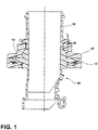
- FIG. 1 is a representative or schematic section view of a valve 10 incorporating a lip seal 12 according to one aspect of the teachings.
- the lip seal 12 may be disposed between a flange 14 surrounding the valve 10 and a weld foot 16 designed or configured to be weldable onto a fuel tank.
- the weld foot 16 may be overmolded onto a valve body 18.
- the valve body 18 may include an interlock surface 20 that, in conjunction with the weld foot 16, may create a labyrinth leak path that makes it difficult for fluid or vapor to escape the valve 10 and may also make the valve 10 resistant to delamination.
- the illustrated lip seal 12 shows the lips 30, 32 deflecting in different directions, the lips 30, 32 may be designed to deflect in the same direction without departing from the scope of the disclosure.
- the material used to manufacture the lip seal 12 can be, for example and without limitation, a low-permeability elastomer with a very high melting temperature so that the lip seal 12 can withstand the temperatures and pressures of an overmolding process.
- the overmolding process may incorporate a floating steel ring inside the tooling.
- the steel ring may be supported by high biasing force springs, such as engine valve springs, against a plurality of stops in the mold.
- high biasing force springs such as engine valve springs
- the floating steel ring may act like a piston and may be compressed against the springs by the plastic.
- the springs can push back and compress the plastic to prevent voids from forming.
Description
- The present teachings relate to valve seals, including a lip structure for a valve seal.
- Valves, such as inline check valves or other valves, may include sealing structures between two valve components to prevent leakage of fluid and/or vapor. In fuel tank applications, for example, the seal prevents fuel from leaking between layers or to the atmosphere. However, various conditions may weaken the sealing capabilities of the seal. For example, high internal pressures in the valve and/or a high differential between the pressures inside and outside the valve may cause leakage. Contamination, flash, or other debris on the sealing surface may also compromise the seal. A valve assembly according to the preamble of claim 1 is disclosed in
US 2005/0139271 A1 . - A valve assembly as defined by the features of claim 1 is provided that is suitable for use in a fuel fill line. The valve assembly includes a housing having a flange that surrounds the housing. A weld foot is molded over at least a portion of the flange. A lip seal is disposed between the flange and the weld foot. The lip seal includes a first lip and a second lip that both contact with a surface on one of the flange and the weld foot.
- Various aspects of the present teachings will become apparent to those skilled in the art from the following detailed description of the embodiments, when read in light of the accompanying drawings.
- Embodiments of the invention will now be described, by way of example, with reference to the accompanying drawings, wherein:
-
FIG. 1 is a schematic section view of a valve having a redundant lip seal according to one aspect of the teachings; -
FIG. 2 is a close-up schematic view of a portion of the valve inFIG. 1 ; and -
FIG. 3 is a closer schematic view of a portion of the valve inFIG. 1 . - Reference will now be made in detail to embodiments of the present disclosure, examples of which are described herein and illustrated in the accompanying drawings. While the invention will be described in conjunction with embodiments, it will be understood that they are not intended to limit the invention to these embodiments. On the contrary, the invention is intended to cover alternatives, modifications and equivalents, which may be included within the spirit and scope of the invention as defined by the appended claims.
- The teachings herein illustrate a valve seal having improved sealing capabilities.
FIG. 1 is a representative or schematic section view of avalve 10 incorporating alip seal 12 according to one aspect of the teachings. Thelip seal 12 may be disposed between aflange 14 surrounding thevalve 10 and aweld foot 16 designed or configured to be weldable onto a fuel tank. In an aspect of the teachings, theweld foot 16 may be overmolded onto avalve body 18. Thevalve body 18 may include aninterlock surface 20 that, in conjunction with theweld foot 16, may create a labyrinth leak path that makes it difficult for fluid or vapor to escape thevalve 10 and may also make thevalve 10 resistant to delamination. - As generally illustrated in
FIG. 2 , aseal ring 19 may be coupled to thelip seal 12 to provide more secure interlocking between thelip seal 12 and theweld foot 16. The configuration may further improve leak-prevention robustness by, for example, preventing thelip seal 12 from being dislocated or deformed during an overmolding process. In an aspect of the teachings, theseal ring 19 may be comprised of metal. However, with embodiments, theseal ring 19 may also be comprised of other appropriate rigid materials, such as, for example, a plastic. Moreover, theseal ring 19 may also have a series of through holes, which for some embodiments or applications may mechanically hold thelip seal 12 in place comparatively better than a smooth surface and/or an adhesive between theseal ring 19 and thelip seal 12. - In embodiments, the
lip seal 12 may have first andsecond lips second lips lip seal 12 regardless of the direction of the pressure differential. This can better ensure a secure seal even when thevalve 10 is tipped. The first andsecond lips lips weld foot 16 is formed onto theflange 14, thelips flange 14 as thelip seal 12 is compressed. In one aspect of the teachings, theflange 14 may include a shelf or step. With such a configuration, theseal ring 19 can be located against the shelf or step and thelips - Although the illustrated
lip seal 12 shows thelips lips lip seal 12 can be, for example and without limitation, a low-permeability elastomer with a very high melting temperature so that thelip seal 12 can withstand the temperatures and pressures of an overmolding process. - The
valve 10 may, if desired, be manufactured using a unique overmolding process. In an embodiment, the overmolding process may contact theseal ring 19 at multiple places to hold theseal ring 19 in place more securely and perhaps also more evenly. - Alternatively, or in addition, the overmolding process may incorporate a floating steel ring inside the tooling. In an embodiment, the steel ring may be supported by high biasing force springs, such as engine valve springs, against a plurality of stops in the mold. When molten, pressurized plastic enters the mold, the floating steel ring may act like a piston and may be compressed against the springs by the plastic. As the plastic cools, shrinks, and hardens, the springs can push back and compress the plastic to prevent voids from forming.
- As a result, the redundant
lip seal structure 12 can prevent leaking regardless of the differential between the pressure inside thevalve 10 versus outside thevalve 10. Moreover, theredundant lip seal 12 can provide extra sealing surfaces to improve its sealing capabilities, even if thelip seal 12 experiences contamination or flash on its sealing surface and/or high pressure operating conditions. - It will be appreciated that the above teachings are merely exemplary in nature and is not intended to limit the present teachings, their application or uses. While specific examples have been described in the specification and illustrated in the drawings, it will be understood by those of ordinary skill in the art that various changes may be made and equivalents may be substituted for elements thereof without departing from the scope of the present teachings as defined in the claims. Furthermore, the mixing and matching of features, elements and/or functions between various examples is expressly contemplated herein so that one of ordinary skill in the art would appreciate from this disclosure that features, elements and/or functions of one example may be incorporated into another example as appropriate, unless described otherwise, above. Moreover, many modifications may be made to adapt a particular situation or material to the teachings of the present disclosure without departing from the essential scope thereof. Therefore, it is intended that the present teachings not be limited to the particular examples illustrated by the drawings and described in the specification as the best mode presently contemplated for carrying out the teachings of the present disclosure, but that the scope of the present disclosure will include any embodiments falling within the foregoing description and the appended claims.
Claims (14)
- A valve assembly (10) for use in a fuel fill line, the valve assembly (10) comprising:a housing including a flange (14) that surrounds the housing;a weld foot (16) molded over at least a portion of the flange (14); anda seal (12) disposed between the flange (14) and the weld foot (16);characterized in that:
the seal (12) includes a first lip (30) and a second lip (32), the first and second lips (30, 32) being configured to provide a labyrinth leak path and wherein the first lip (30) and second lip (32) are both in contact with a surface on one of the flange (14) and the weld foot (16). - The valve assembly (10) of claim 1, wherein the housing includes an interlock surface (20), and a portion of the weld foot (16) is molded over the interlock surface (20).
- The valve assembly (10) of claim 1, wherein the seal (12) is coupled to a seal ring (19), and the seal ring (19) is configured to provide support for the seal (12).
- The valve assembly (10) of claim 3, wherein the seal ring (19) includes a plurality of through holes for mechanical engagement between the seal (12) and the seal ring (19).
- The valve assembly (10) of claim 3, wherein the seal (12) and the seal ring (19) are over-molded between the flange (14) and the weld foot (16).
- The valve assembly (10) of claim 3, wherein the flange (14) forms a stepped portion and the seal ring (19) engages the stepped portion to maintain deflection of the first and second lips (30, 32) of the seal (12) against the flange (14).
- The valve assembly (10) of claim 1, wherein the first lip (30) of the seal (12) extends in a first direction and the second lip (32) of the seal (12) extends in a second direction.
- The valve assembly (10) of claim 1, wherein the first and second lips (30, 32) of the seal (12) are in contact with a surface of the flange (14).
- The valve assembly (10) of claim 1
wherein the seal is a lip seal (12) and the first lip (30) and the second lip (32) are spaced apart from one another and are in contact with the surface of the flange (14). - The valve assembly (10) of claim 9, wherein the housing includes an interlock surface (20) and a portion of the weld foot (16) is molded over the interlock surface (20).
- The valve assembly (10) of claim 9, wherein the lip seal (12) is coupled to a seal ring (19) that provides support for the lip seal (12).
- The valve assembly (10) of claim 11, wherein the seal ring (19) includes a plurality of through holes for mechanical engagement between the lip seal (12) and the seal ring (19) and wherein the lip seal (12) and the seal ring (19) are over-molded between the flange (14) and the weld foot (16).
- The valve assembly (10) of claim 11, wherein the flange (14) forms a stepped portion, and the seal ring (19) engages the stepped portion to maintain uniform deflection of the first and second lips (30, 32) of the lip seal (12) against the flange (14).
- The valve assembly (10) of claim 1, wherein the first lip (30) of the lip seal (12) extends in a first direction and the second lip (32) of the lip seal (12) extends in a second direction that is generally opposite the first direction.
Priority Applications (1)
| Application Number | Priority Date | Filing Date | Title |
|---|---|---|---|
| EP19208664.3A EP3626500B1 (en) | 2012-07-30 | 2013-03-15 | Valve having redundant lip seal |
Applications Claiming Priority (2)
| Application Number | Priority Date | Filing Date | Title |
|---|---|---|---|
| US201261677245P | 2012-07-30 | 2012-07-30 | |
| PCT/US2013/031859 WO2014021944A1 (en) | 2012-07-30 | 2013-03-15 | Redundant lip seal for valve |
Related Child Applications (1)
| Application Number | Title | Priority Date | Filing Date |
|---|---|---|---|
| EP19208664.3A Division EP3626500B1 (en) | 2012-07-30 | 2013-03-15 | Valve having redundant lip seal |
Publications (2)
| Publication Number | Publication Date |
|---|---|
| EP2879894A1 EP2879894A1 (en) | 2015-06-10 |
| EP2879894B1 true EP2879894B1 (en) | 2019-11-20 |
Family
ID=48048210
Family Applications (2)
| Application Number | Title | Priority Date | Filing Date |
|---|---|---|---|
| EP13714408.5A Active EP2879894B1 (en) | 2012-07-30 | 2013-03-15 | Redundant lip seal for valve |
| EP19208664.3A Active EP3626500B1 (en) | 2012-07-30 | 2013-03-15 | Valve having redundant lip seal |
Family Applications After (1)
| Application Number | Title | Priority Date | Filing Date |
|---|---|---|---|
| EP19208664.3A Active EP3626500B1 (en) | 2012-07-30 | 2013-03-15 | Valve having redundant lip seal |
Country Status (7)
| Country | Link |
|---|---|
| US (1) | US10184583B2 (en) |
| EP (2) | EP2879894B1 (en) |
| JP (1) | JP2015529592A (en) |
| KR (1) | KR20150037928A (en) |
| CN (2) | CN103574157A (en) |
| IN (1) | IN2015DN00257A (en) |
| WO (1) | WO2014021944A1 (en) |
Families Citing this family (5)
| Publication number | Priority date | Publication date | Assignee | Title |
|---|---|---|---|---|
| JP2015529592A (en) * | 2012-07-30 | 2015-10-08 | イートン コーポレーションEaton Corporation | Multiple lip seals for valves |
| US10718375B2 (en) | 2016-05-16 | 2020-07-21 | Roller Bearing Company Of America, Inc. | Bearing system with self-lubrication features, seals, grooves and slots for maintenance-free operation |
| US11473626B2 (en) | 2016-05-16 | 2022-10-18 | Roller Bearing Company Of America, Inc. | Bearing system with self-lubrication features, seals, grooves and slots for maintenance-free operation |
| DE112018001291T5 (en) | 2017-04-10 | 2020-01-02 | Eaton Intelligent Power Limited | VAPOR PRESSURE SENSOR ASSEMBLY |
| EP3608033A4 (en) | 2017-04-17 | 2020-05-06 | Mazda Motor Corporation | Rivet bonding mold |
Family Cites Families (23)
| Publication number | Priority date | Publication date | Assignee | Title |
|---|---|---|---|---|
| GB762232A (en) * | 1954-05-22 | 1956-11-28 | Wright Howard Clayton Ltd | A new or improved sealing ring |
| DE1950815A1 (en) * | 1969-10-09 | 1971-04-22 | Brumme Kg Effbe Werk | Seal for a petrol tank cap |
| DE2507463A1 (en) * | 1975-02-21 | 1976-09-09 | Erhard Ing Grad Joos | Storage tank hatch mounting - holds coverplate and seal in compact bolted assembly |
| JPH0378141U (en) | 1989-12-01 | 1991-08-07 | ||
| SE468957B (en) | 1991-08-21 | 1993-04-19 | Mattsson Ab F M | FLOW VALVE AND METAL FORM TOOL FOR MANUFACTURE OF SAETE OR CONE |
| JP2586741Y2 (en) * | 1992-07-30 | 1998-12-09 | エヌティエヌ株式会社 | Bearing sealing device |
| US5364244A (en) | 1993-08-26 | 1994-11-15 | Carr-Griff, Inc. | Pump arrangement including flag type inlet valves with spherical seating |
| JP2683880B2 (en) | 1994-01-31 | 1997-12-03 | 博 横田 | Combined actuation non-water hammer check valve device |
| TWI259501B (en) * | 2000-12-07 | 2006-08-01 | Shinetsu Polymer Co | Seal and substrate container using same |
| AUPR534301A0 (en) | 2001-05-30 | 2001-06-21 | Joe Santa & Associates Pty Limited | A pump valve |
| JP2003097725A (en) * | 2001-09-27 | 2003-04-03 | Nok Corp | Sealing device |
| US7458391B2 (en) * | 2001-12-21 | 2008-12-02 | Eaton Corporation | Assembling a siphonable filler tube with a check valve on a fuel tank |
| US7690527B2 (en) * | 2003-07-28 | 2010-04-06 | Gary Englund | Shaped sealing gasket |
| JP4411911B2 (en) * | 2003-09-10 | 2010-02-10 | Nok株式会社 | Sealing device |
| JP4255363B2 (en) * | 2003-11-19 | 2009-04-15 | 株式会社ニフコ | Valve element for check valve |
| JP4634772B2 (en) * | 2004-10-14 | 2011-02-16 | ミライアル株式会社 | Storage container |
| JP2006342829A (en) * | 2005-06-07 | 2006-12-21 | Nok Corp | Sealing device |
| JP4311409B2 (en) * | 2006-03-27 | 2009-08-12 | 東海ゴム工業株式会社 | Elastic seal member for fuel tank |
| US8584704B2 (en) * | 2009-04-22 | 2013-11-19 | Eaton Corporation | Valve assembly for high-pressure fluid reservoir |
| JP5725277B2 (en) * | 2010-06-14 | 2015-05-27 | Nok株式会社 | gasket |
| IN2014DN09249A (en) * | 2012-05-10 | 2015-07-10 | Eaton Corp | |
| JP2015529592A (en) * | 2012-07-30 | 2015-10-08 | イートン コーポレーションEaton Corporation | Multiple lip seals for valves |
| EP3183138A4 (en) * | 2014-08-19 | 2018-04-18 | Eaton Corporation | Extension tube internal check valve |
-
2013
- 2013-03-15 JP JP2015525418A patent/JP2015529592A/en active Pending
- 2013-03-15 EP EP13714408.5A patent/EP2879894B1/en active Active
- 2013-03-15 WO PCT/US2013/031859 patent/WO2014021944A1/en active Application Filing
- 2013-03-15 EP EP19208664.3A patent/EP3626500B1/en active Active
- 2013-03-15 KR KR20157002434A patent/KR20150037928A/en not_active Application Discontinuation
- 2013-07-25 CN CN201310316265.8A patent/CN103574157A/en active Pending
- 2013-07-25 CN CN201320446401.0U patent/CN203628014U/en not_active Expired - Lifetime
-
2014
- 2014-12-23 US US14/580,459 patent/US10184583B2/en active Active
-
2015
- 2015-01-12 IN IN257DEN2015 patent/IN2015DN00257A/en unknown
Non-Patent Citations (1)
| Title |
|---|
| None * |
Also Published As
| Publication number | Publication date |
|---|---|
| EP3626500B1 (en) | 2021-05-19 |
| JP2015529592A (en) | 2015-10-08 |
| IN2015DN00257A (en) | 2015-06-12 |
| CN203628014U (en) | 2014-06-04 |
| EP3626500A1 (en) | 2020-03-25 |
| EP2879894A1 (en) | 2015-06-10 |
| US10184583B2 (en) | 2019-01-22 |
| WO2014021944A1 (en) | 2014-02-06 |
| KR20150037928A (en) | 2015-04-08 |
| US20150107700A1 (en) | 2015-04-23 |
| CN103574157A (en) | 2014-02-12 |
Similar Documents
| Publication | Publication Date | Title |
|---|---|---|
| US10184583B2 (en) | Redundant lip seal for valve | |
| US7556171B2 (en) | Tank | |
| US8608173B2 (en) | Method and apparatus to provide sealing contact between first and second fueldraulic components | |
| US10671100B2 (en) | Unit for the regulation or control of a fluid pressure | |
| US10215283B2 (en) | Sealing device | |
| JP2005090569A (en) | Sealing device for reciprocating shaft | |
| JP7178178B2 (en) | Seal ring | |
| JP5374559B2 (en) | Sealing structure | |
| US20080226862A1 (en) | Barrier Gasket | |
| US20170074401A1 (en) | Press-in-place gasket | |
| US9447878B2 (en) | Piston seal assembly | |
| US20060290068A1 (en) | Radially assembled seal | |
| WO2008013281A1 (en) | Seal ring | |
| EP1164317A2 (en) | Sealing structure for joint of housing parts | |
| JP2011112202A (en) | Piston ring | |
| KR20170000076U (en) | Multi kammprofile gasket | |
| JP5847899B1 (en) | High pressure gas seal | |
| US20180119660A1 (en) | Unit for Regulating or Controlling a Fluid Pressure | |
| JP4835093B2 (en) | Pressure-resistant fluoroscopic window sealing device | |
| US9739318B2 (en) | Clutch piston assembly | |
| US10634251B2 (en) | Multi-layer gasket assembly | |
| JP2009068672A (en) | Sealing device, and its manufacturing method | |
| KR20190012223A (en) | Method for manufacturing grooved and grooved ring seals | |
| US20060038352A1 (en) | Seal unit with integrated connection means and mechanical assembly using said seal unit | |
| JP5153576B2 (en) | Shaft seal device |
Legal Events
| Date | Code | Title | Description |
|---|---|---|---|
| PUAI | Public reference made under article 153(3) epc to a published international application that has entered the european phase |
Free format text: ORIGINAL CODE: 0009012 |
|
| 17P | Request for examination filed |
Effective date: 20150108 |
|
| AK | Designated contracting states |
Kind code of ref document: A1 Designated state(s): AL AT BE BG CH CY CZ DE DK EE ES FI FR GB GR HR HU IE IS IT LI LT LU LV MC MK MT NL NO PL PT RO RS SE SI SK SM TR |
|
| AX | Request for extension of the european patent |
Extension state: BA ME |
|
| DAX | Request for extension of the european patent (deleted) | ||
| STAA | Information on the status of an ep patent application or granted ep patent |
Free format text: STATUS: EXAMINATION IS IN PROGRESS |
|
| 17Q | First examination report despatched |
Effective date: 20181115 |
|
| GRAP | Despatch of communication of intention to grant a patent |
Free format text: ORIGINAL CODE: EPIDOSNIGR1 |
|
| STAA | Information on the status of an ep patent application or granted ep patent |
Free format text: STATUS: GRANT OF PATENT IS INTENDED |
|
| INTG | Intention to grant announced |
Effective date: 20190618 |
|
| GRAS | Grant fee paid |
Free format text: ORIGINAL CODE: EPIDOSNIGR3 |
|
| GRAA | (expected) grant |
Free format text: ORIGINAL CODE: 0009210 |
|
| STAA | Information on the status of an ep patent application or granted ep patent |
Free format text: STATUS: THE PATENT HAS BEEN GRANTED |
|
| AK | Designated contracting states |
Kind code of ref document: B1 Designated state(s): AL AT BE BG CH CY CZ DE DK EE ES FI FR GB GR HR HU IE IS IT LI LT LU LV MC MK MT NL NO PL PT RO RS SE SI SK SM TR |
|
| REG | Reference to a national code |
Ref country code: GB Ref legal event code: FG4D |
|
| REG | Reference to a national code |
Ref country code: CH Ref legal event code: EP |
|
| REG | Reference to a national code |
Ref country code: IE Ref legal event code: FG4D |
|
| REG | Reference to a national code |
Ref country code: DE Ref legal event code: R096 Ref document number: 602013063077 Country of ref document: DE |
|
| REG | Reference to a national code |
Ref country code: AT Ref legal event code: REF Ref document number: 1203801 Country of ref document: AT Kind code of ref document: T Effective date: 20191215 |
|
| REG | Reference to a national code |
Ref country code: NL Ref legal event code: MP Effective date: 20191120 |
|
| REG | Reference to a national code |
Ref country code: LT Ref legal event code: MG4D |
|
| PG25 | Lapsed in a contracting state [announced via postgrant information from national office to epo] |
Ref country code: LV Free format text: LAPSE BECAUSE OF FAILURE TO SUBMIT A TRANSLATION OF THE DESCRIPTION OR TO PAY THE FEE WITHIN THE PRESCRIBED TIME-LIMIT Effective date: 20191120 Ref country code: SE Free format text: LAPSE BECAUSE OF FAILURE TO SUBMIT A TRANSLATION OF THE DESCRIPTION OR TO PAY THE FEE WITHIN THE PRESCRIBED TIME-LIMIT Effective date: 20191120 Ref country code: BG Free format text: LAPSE BECAUSE OF FAILURE TO SUBMIT A TRANSLATION OF THE DESCRIPTION OR TO PAY THE FEE WITHIN THE PRESCRIBED TIME-LIMIT Effective date: 20200220 Ref country code: FI Free format text: LAPSE BECAUSE OF FAILURE TO SUBMIT A TRANSLATION OF THE DESCRIPTION OR TO PAY THE FEE WITHIN THE PRESCRIBED TIME-LIMIT Effective date: 20191120 Ref country code: LT Free format text: LAPSE BECAUSE OF FAILURE TO SUBMIT A TRANSLATION OF THE DESCRIPTION OR TO PAY THE FEE WITHIN THE PRESCRIBED TIME-LIMIT Effective date: 20191120 Ref country code: GR Free format text: LAPSE BECAUSE OF FAILURE TO SUBMIT A TRANSLATION OF THE DESCRIPTION OR TO PAY THE FEE WITHIN THE PRESCRIBED TIME-LIMIT Effective date: 20200221 Ref country code: NO Free format text: LAPSE BECAUSE OF FAILURE TO SUBMIT A TRANSLATION OF THE DESCRIPTION OR TO PAY THE FEE WITHIN THE PRESCRIBED TIME-LIMIT Effective date: 20200220 Ref country code: NL Free format text: LAPSE BECAUSE OF FAILURE TO SUBMIT A TRANSLATION OF THE DESCRIPTION OR TO PAY THE FEE WITHIN THE PRESCRIBED TIME-LIMIT Effective date: 20191120 Ref country code: ES Free format text: LAPSE BECAUSE OF FAILURE TO SUBMIT A TRANSLATION OF THE DESCRIPTION OR TO PAY THE FEE WITHIN THE PRESCRIBED TIME-LIMIT Effective date: 20191120 |
|
| PG25 | Lapsed in a contracting state [announced via postgrant information from national office to epo] |
Ref country code: HR Free format text: LAPSE BECAUSE OF FAILURE TO SUBMIT A TRANSLATION OF THE DESCRIPTION OR TO PAY THE FEE WITHIN THE PRESCRIBED TIME-LIMIT Effective date: 20191120 Ref country code: IS Free format text: LAPSE BECAUSE OF FAILURE TO SUBMIT A TRANSLATION OF THE DESCRIPTION OR TO PAY THE FEE WITHIN THE PRESCRIBED TIME-LIMIT Effective date: 20200320 Ref country code: RS Free format text: LAPSE BECAUSE OF FAILURE TO SUBMIT A TRANSLATION OF THE DESCRIPTION OR TO PAY THE FEE WITHIN THE PRESCRIBED TIME-LIMIT Effective date: 20191120 |
|
| PG25 | Lapsed in a contracting state [announced via postgrant information from national office to epo] |
Ref country code: AL Free format text: LAPSE BECAUSE OF FAILURE TO SUBMIT A TRANSLATION OF THE DESCRIPTION OR TO PAY THE FEE WITHIN THE PRESCRIBED TIME-LIMIT Effective date: 20191120 |
|
| PG25 | Lapsed in a contracting state [announced via postgrant information from national office to epo] |
Ref country code: PT Free format text: LAPSE BECAUSE OF FAILURE TO SUBMIT A TRANSLATION OF THE DESCRIPTION OR TO PAY THE FEE WITHIN THE PRESCRIBED TIME-LIMIT Effective date: 20200412 Ref country code: EE Free format text: LAPSE BECAUSE OF FAILURE TO SUBMIT A TRANSLATION OF THE DESCRIPTION OR TO PAY THE FEE WITHIN THE PRESCRIBED TIME-LIMIT Effective date: 20191120 Ref country code: RO Free format text: LAPSE BECAUSE OF FAILURE TO SUBMIT A TRANSLATION OF THE DESCRIPTION OR TO PAY THE FEE WITHIN THE PRESCRIBED TIME-LIMIT Effective date: 20191120 Ref country code: CZ Free format text: LAPSE BECAUSE OF FAILURE TO SUBMIT A TRANSLATION OF THE DESCRIPTION OR TO PAY THE FEE WITHIN THE PRESCRIBED TIME-LIMIT Effective date: 20191120 Ref country code: DK Free format text: LAPSE BECAUSE OF FAILURE TO SUBMIT A TRANSLATION OF THE DESCRIPTION OR TO PAY THE FEE WITHIN THE PRESCRIBED TIME-LIMIT Effective date: 20191120 |
|
| REG | Reference to a national code |
Ref country code: AT Ref legal event code: MK05 Ref document number: 1203801 Country of ref document: AT Kind code of ref document: T Effective date: 20191120 |
|
| REG | Reference to a national code |
Ref country code: DE Ref legal event code: R097 Ref document number: 602013063077 Country of ref document: DE |
|
| PG25 | Lapsed in a contracting state [announced via postgrant information from national office to epo] |
Ref country code: SM Free format text: LAPSE BECAUSE OF FAILURE TO SUBMIT A TRANSLATION OF THE DESCRIPTION OR TO PAY THE FEE WITHIN THE PRESCRIBED TIME-LIMIT Effective date: 20191120 Ref country code: SK Free format text: LAPSE BECAUSE OF FAILURE TO SUBMIT A TRANSLATION OF THE DESCRIPTION OR TO PAY THE FEE WITHIN THE PRESCRIBED TIME-LIMIT Effective date: 20191120 |
|
| PLBE | No opposition filed within time limit |
Free format text: ORIGINAL CODE: 0009261 |
|
| STAA | Information on the status of an ep patent application or granted ep patent |
Free format text: STATUS: NO OPPOSITION FILED WITHIN TIME LIMIT |
|
| 26N | No opposition filed |
Effective date: 20200821 |
|
| PG25 | Lapsed in a contracting state [announced via postgrant information from national office to epo] |
Ref country code: MC Free format text: LAPSE BECAUSE OF FAILURE TO SUBMIT A TRANSLATION OF THE DESCRIPTION OR TO PAY THE FEE WITHIN THE PRESCRIBED TIME-LIMIT Effective date: 20191120 |
|
| REG | Reference to a national code |
Ref country code: CH Ref legal event code: PL |
|
| PG25 | Lapsed in a contracting state [announced via postgrant information from national office to epo] |
Ref country code: SI Free format text: LAPSE BECAUSE OF FAILURE TO SUBMIT A TRANSLATION OF THE DESCRIPTION OR TO PAY THE FEE WITHIN THE PRESCRIBED TIME-LIMIT Effective date: 20191120 Ref country code: AT Free format text: LAPSE BECAUSE OF FAILURE TO SUBMIT A TRANSLATION OF THE DESCRIPTION OR TO PAY THE FEE WITHIN THE PRESCRIBED TIME-LIMIT Effective date: 20191120 Ref country code: PL Free format text: LAPSE BECAUSE OF FAILURE TO SUBMIT A TRANSLATION OF THE DESCRIPTION OR TO PAY THE FEE WITHIN THE PRESCRIBED TIME-LIMIT Effective date: 20191120 |
|
| REG | Reference to a national code |
Ref country code: BE Ref legal event code: MM Effective date: 20200331 |
|
| PG25 | Lapsed in a contracting state [announced via postgrant information from national office to epo] |
Ref country code: LU Free format text: LAPSE BECAUSE OF NON-PAYMENT OF DUE FEES Effective date: 20200315 |
|
| PG25 | Lapsed in a contracting state [announced via postgrant information from national office to epo] |
Ref country code: FR Free format text: LAPSE BECAUSE OF NON-PAYMENT OF DUE FEES Effective date: 20200331 Ref country code: IE Free format text: LAPSE BECAUSE OF NON-PAYMENT OF DUE FEES Effective date: 20200315 Ref country code: IT Free format text: LAPSE BECAUSE OF FAILURE TO SUBMIT A TRANSLATION OF THE DESCRIPTION OR TO PAY THE FEE WITHIN THE PRESCRIBED TIME-LIMIT Effective date: 20191120 Ref country code: LI Free format text: LAPSE BECAUSE OF NON-PAYMENT OF DUE FEES Effective date: 20200331 Ref country code: CH Free format text: LAPSE BECAUSE OF NON-PAYMENT OF DUE FEES Effective date: 20200331 |
|
| PG25 | Lapsed in a contracting state [announced via postgrant information from national office to epo] |
Ref country code: BE Free format text: LAPSE BECAUSE OF NON-PAYMENT OF DUE FEES Effective date: 20200331 |
|
| GBPC | Gb: european patent ceased through non-payment of renewal fee |
Effective date: 20200315 |
|
| PG25 | Lapsed in a contracting state [announced via postgrant information from national office to epo] |
Ref country code: GB Free format text: LAPSE BECAUSE OF NON-PAYMENT OF DUE FEES Effective date: 20200315 |
|
| PG25 | Lapsed in a contracting state [announced via postgrant information from national office to epo] |
Ref country code: TR Free format text: LAPSE BECAUSE OF FAILURE TO SUBMIT A TRANSLATION OF THE DESCRIPTION OR TO PAY THE FEE WITHIN THE PRESCRIBED TIME-LIMIT Effective date: 20191120 Ref country code: MT Free format text: LAPSE BECAUSE OF FAILURE TO SUBMIT A TRANSLATION OF THE DESCRIPTION OR TO PAY THE FEE WITHIN THE PRESCRIBED TIME-LIMIT Effective date: 20191120 Ref country code: CY Free format text: LAPSE BECAUSE OF FAILURE TO SUBMIT A TRANSLATION OF THE DESCRIPTION OR TO PAY THE FEE WITHIN THE PRESCRIBED TIME-LIMIT Effective date: 20191120 |
|
| PG25 | Lapsed in a contracting state [announced via postgrant information from national office to epo] |
Ref country code: MK Free format text: LAPSE BECAUSE OF FAILURE TO SUBMIT A TRANSLATION OF THE DESCRIPTION OR TO PAY THE FEE WITHIN THE PRESCRIBED TIME-LIMIT Effective date: 20191120 |
|
| PGFP | Annual fee paid to national office [announced via postgrant information from national office to epo] |
Ref country code: DE Payment date: 20230221 Year of fee payment: 11 |
|
| P01 | Opt-out of the competence of the unified patent court (upc) registered |
Effective date: 20230521 |