EP2878799A1 - Fuel injector device - Google Patents
Fuel injector device Download PDFInfo
- Publication number
- EP2878799A1 EP2878799A1 EP12881776.4A EP12881776A EP2878799A1 EP 2878799 A1 EP2878799 A1 EP 2878799A1 EP 12881776 A EP12881776 A EP 12881776A EP 2878799 A1 EP2878799 A1 EP 2878799A1
- Authority
- EP
- European Patent Office
- Prior art keywords
- heater
- temperature
- fuel
- estimated
- fuel injection
- Prior art date
- Legal status (The legal status is an assumption and is not a legal conclusion. Google has not performed a legal analysis and makes no representation as to the accuracy of the status listed.)
- Granted
Links
- 239000000446 fuel Substances 0.000 title claims abstract description 115
- 238000009835 boiling Methods 0.000 claims abstract description 59
- 238000002347 injection Methods 0.000 claims abstract description 44
- 239000007924 injection Substances 0.000 claims abstract description 44
- 238000012937 correction Methods 0.000 claims description 27
- 238000010438 heat treatment Methods 0.000 abstract description 6
- 238000002485 combustion reaction Methods 0.000 description 11
- 238000000034 method Methods 0.000 description 8
- 238000012545 processing Methods 0.000 description 7
- 238000010586 diagram Methods 0.000 description 6
- 230000004907 flux Effects 0.000 description 5
- LFQSCWFLJHTTHZ-UHFFFAOYSA-N Ethanol Chemical compound CCO LFQSCWFLJHTTHZ-UHFFFAOYSA-N 0.000 description 3
- 238000012546 transfer Methods 0.000 description 3
- 238000000889 atomisation Methods 0.000 description 2
- 230000006835 compression Effects 0.000 description 2
- 238000007906 compression Methods 0.000 description 2
- 239000007788 liquid Substances 0.000 description 2
- 238000002663 nebulization Methods 0.000 description 2
- 239000004215 Carbon black (E152) Substances 0.000 description 1
- 239000000470 constituent Substances 0.000 description 1
- 239000000498 cooling water Substances 0.000 description 1
- 230000003247 decreasing effect Effects 0.000 description 1
- 238000013461 design Methods 0.000 description 1
- 239000002828 fuel tank Substances 0.000 description 1
- 239000003502 gasoline Substances 0.000 description 1
- 229930195733 hydrocarbon Natural products 0.000 description 1
- 150000002430 hydrocarbons Chemical class 0.000 description 1
- 230000002452 interceptive effect Effects 0.000 description 1
- 239000000203 mixture Substances 0.000 description 1
- 230000002250 progressing effect Effects 0.000 description 1
- 229920006395 saturated elastomer Polymers 0.000 description 1
Images


Classifications
-
- F—MECHANICAL ENGINEERING; LIGHTING; HEATING; WEAPONS; BLASTING
- F02—COMBUSTION ENGINES; HOT-GAS OR COMBUSTION-PRODUCT ENGINE PLANTS
- F02M—SUPPLYING COMBUSTION ENGINES IN GENERAL WITH COMBUSTIBLE MIXTURES OR CONSTITUENTS THEREOF
- F02M53/00—Fuel-injection apparatus characterised by having heating, cooling or thermally-insulating means
- F02M53/04—Injectors with heating, cooling, or thermally-insulating means
- F02M53/06—Injectors with heating, cooling, or thermally-insulating means with fuel-heating means, e.g. for vaporising
-
- F—MECHANICAL ENGINEERING; LIGHTING; HEATING; WEAPONS; BLASTING
- F02—COMBUSTION ENGINES; HOT-GAS OR COMBUSTION-PRODUCT ENGINE PLANTS
- F02M—SUPPLYING COMBUSTION ENGINES IN GENERAL WITH COMBUSTIBLE MIXTURES OR CONSTITUENTS THEREOF
- F02M53/00—Fuel-injection apparatus characterised by having heating, cooling or thermally-insulating means
- F02M53/02—Fuel-injection apparatus characterised by having heating, cooling or thermally-insulating means with fuel-heating means, e.g. for vaporising
-
- F—MECHANICAL ENGINEERING; LIGHTING; HEATING; WEAPONS; BLASTING
- F02—COMBUSTION ENGINES; HOT-GAS OR COMBUSTION-PRODUCT ENGINE PLANTS
- F02M—SUPPLYING COMBUSTION ENGINES IN GENERAL WITH COMBUSTIBLE MIXTURES OR CONSTITUENTS THEREOF
- F02M61/00—Fuel-injectors not provided for in groups F02M39/00 - F02M57/00 or F02M67/00
- F02M61/04—Fuel-injectors not provided for in groups F02M39/00 - F02M57/00 or F02M67/00 having valves, e.g. having a plurality of valves in series
-
- F—MECHANICAL ENGINEERING; LIGHTING; HEATING; WEAPONS; BLASTING
- F02—COMBUSTION ENGINES; HOT-GAS OR COMBUSTION-PRODUCT ENGINE PLANTS
- F02M—SUPPLYING COMBUSTION ENGINES IN GENERAL WITH COMBUSTIBLE MIXTURES OR CONSTITUENTS THEREOF
- F02M31/00—Apparatus for thermally treating combustion-air, fuel, or fuel-air mixture
- F02M31/02—Apparatus for thermally treating combustion-air, fuel, or fuel-air mixture for heating
- F02M31/12—Apparatus for thermally treating combustion-air, fuel, or fuel-air mixture for heating electrically
- F02M31/125—Fuel
Definitions
- the present invention relates to a fuel injection system, and more particular to a fuel injection system which includes a heater for heating fuel before being injected from a fuel injection valve.
- Patent Document 1 discloses a fuel injection system for an internal combustion engine.
- a fuel injection valve in this conventional system incorporates a heater for heating fuel immediately before being injected.
- This heater is configured to produce heat by receiving a supply of electric power from a predetermined electric power source.
- the resistance value of the heater is set to a value within a predetermined range so that the surface temperature of the heater falls within a predetermined temperature range in which a deposit does not adhere.
- the temperature of the heater can be estimated on the basis of an unambiguous relationship with the resistance value of the heater.
- the resistance value of the heater can be calculated on the basis of electric voltage that is applied to the heater (voltage between both ends of the heater) and electric current that flows through the heater.
- an error may be produced in the estimated temperature value of the heater due to factors of variations concerning its hardware (for example, a variation in the resistance value of the heater, and a variation in the resistance value of a wire harness that supplies the heater with electric power).
- the present invention has been made to solve the problem as described above, and has its object to provide a fuel injection system that includes a fuel injection valve in which fuel is heated by a heater before being injected and that can favorably improve the estimation accuracy of the heater temperature.
- the present invention is a fuel injection system, which includes a fuel injection valve, a heater, heater temperature estimation means and heater temperature correction means.
- the fuel injection valve is configured to inject fuel.
- the heater is configured to receive a supply of electric power from a predetermined power source and heats fuel before the fuel is injected from the fuel injection valve.
- the heater temperature estimation means estimates the temperature of the heater on the basis of the resistance value of the heater.
- the heater temperature correction means corrects the temperature of the heater estimated by the heater temperature estimation means so that the difference between the nucleate boiling start point temperature of the fuel and an estimated temperature value of the heater at the time of occurrence of a point of inflection in the resistance value of the heater after energization to the heater is started is reduced.
- the nucleate boiling start point in which nucleate boiling starts to occur in the fuel that is heated by the heater comes, a point of inflection occurs in the resistance value of the heater.
- the nucleate boiling start point temperature of fuel is unambiguously defined on the basis of fuel property and fuel pressure.
- the temperature of the heater estimated by the heater temperature estimation means is corrected in order to reduce the difference between the nucleate boiling start point temperature of the fuel and an estimated temperature value of the heater at the time of occurrence of the point of inflection in the resistance value of the heater after energization to the heater is started.
- the estimation accuracy of the heater temperature can be enhanced by performing such correction processing of the estimated heater temperature value.
- the heater temperature correction means in the present invention may provide a correction to reduce the difference with respect to the temperature of the heater estimated by the heater temperature estimation means at or after the time of occurrence of the point of inflection. According to such configuration, the correction for the heater temperature in the present invention is continuously performed with respect to the heater temperature estimated by the heater temperature estimation means at or after the time of occurrence of the aforementioned point of inflection. This can efficiently enhance the estimation accuracy of the heater temperature.
- the correction performed by the heater temperature correction means in the present invention may correct the temperature of the heater estimated by the heater temperature estimation means so as to reduce the difference to zero. According to such configuration, a correction to reduce to zero the aforementioned difference is performed at the time of occurrence of the point of inflection in the resistance value of the heater, as a preferred manner of the correction of the heater temperature in the present invention. This can efficiently enhance the estimation accuracy of the heater temperature.
- Fig. 1 is a diagram for explaining a configuration of the main part of a fuel injection system according to a first embodiment of the present invention.
- the fuel injection system of the present embodiment includes a fuel injection valve 10 as shown in Fig. 1 .
- the fuel injection valve 10 is used to inject fuel with respect to a combustion chamber or an intake passage of an internal combustion engine. Fuel pressurized by a fuel pump (not shown) is supplied to the fuel injection valve 10 from a fuel inlet 12.
- the fuel injection valve 10 is formed into a substantially cylindrical shape, and the fuel that was supplied from its one end (fuel inlet 12) is injected from a nozzle hole 14 formed at the other end after flowing through the inside of the fuel injection valve 10.
- a needle valve 16 is accommodated in the fuel injection valve 10 so as to be movable in its axial direction.
- the needle valve 16 is driven by an electro-magnetic drive unit 18 to move in the axial direction and, as a result, the nozzle hole 14 opens and closes.
- the electro-magnetic drive unit 18 includes, as main constituent parts, an electro-magnetic coil 18a, an armature 18b and a compression spring 18c.
- a heater 20 is incorporated into the fuel injection valve 10 at a location at which the heater 20 comes into contact with fuel that flows through a fuel flow passage that is formed into the fuel injection valve 10.
- the heater 20 receives a supply of electric power from a predetermined electric power source (for example, a battery of a vehicle in which an internal combustion engine having the fuel injection valve 10 is mounted), and includes a heat resistive element having characteristics (PTC (Positive Temperature Coefficient)) that when its temperature increases, its electric resistance value increases.
- a predetermined electric power source for example, a battery of a vehicle in which an internal combustion engine having the fuel injection valve 10 is mounted
- the system shown in Fig. 1 includes an Electronic Control Unit (ECU) 30.
- the ECU 30 is configured as a known microcomputer in which a ROM, a RAM, a CPU, input ports and output ports that are not shown are connected with one another by interactive buses.
- the ECU 30 uses the electric power source, such as the aforementioned battery, to start or stop the energization to a terminal 22 of the fuel injection valve 10 and thereby controls a time period of the energization to the fuel injection valve 10.
- the ECU 30 uses the electric power source, such as the aforementioned battery, to pass electric current through the heater 20 via a conducting terminal 24 over a predetermined time period and thereby supplies a predetermined amount of electric power.
- the ECU 30 reads signals of various sensors (not shown) that detect the operational state of the internal combustion engine (for example, an engine speed, intake air amount and cooling water temperature), and controls the energization of the fuel injection valve 10 and the energization of the heater 20 in accordance with predetermined programs.
- various sensors not shown
- the operational state of the internal combustion engine for example, an engine speed, intake air amount and cooling water temperature
- the fuel injection valve 10 of the present embodiment is configured so that fuel is heated by the built-in heater 20 immediately before being injected from the nozzle hole 14.
- the ECU 30 starts the energization of the heater 20 when detecting an operation of an ignition switch (not shown) to an ON state at the time of a cold start of the internal combustion engine. If fuel injection by the fuel injection valve 10 is performed in a state in which such energization to the heater 20 has been made, fuel that flows through the inside of the fuel injection valve 10 is injected from the nozzle hole 14 after the fuel is heated by the heater 20. Injecting the heated fuel from the nozzle hole 14 can boost fuel atomization (nebulization). This makes it possible to sufficiently reduce exhaust emissions.
- a drive voltage (herein, a battery voltage as one example) is applied via a wire harness (electric wires) that are not shown. It is assumed that a part of the wire harness includes the aforementioned conducting terminal 24.
- the ECU 30 is configured so as to be able to detect two inputs, that is, the battery voltage and a voltage drop V WH in the wire harness as a whole.
- the electric resistance value of the wire harness as a whole is referred to as R WH .
- the electric resistance value R WH itself is stored in the ECU 30 as a design value.
- the ECU 30 use the electric resistance value R WH as a so-called shunt resistance, and calculates electric current I that flows through the heater 20 on the basis of the voltage drop V WH .
- the ECU 30 calculates the resistance value of the heater 20 (the internal resistance value) R Htr on the basis of the calculated electric current value I and the electric voltage V Htr between both ends of the heater 20 (the value obtained by subtracting the voltage drop V WH from the battery voltage). There exists an unambiguous relationship between the resistance value R Htr and temperature of the heater 20. The ECU 30 stores such relationship. Therefore, the ECU 30 can calculate the estimated temperature value of the heater on the basis of such relationship and the calculated resistance value R Htr of the heater 20.
- Fig. 2 is a diagram showing the boiling curve of fuel. More specifically, Fig. 2 represents boiling phenomena of fuel that is liquid, with a relationship between the heat flux between a heat transfer surface (the surface of the heater 20) and fuel, and the difference (degree of superheat) of the temperature of the heat transfer surface (the surface temperature of the heater 20) with respect to the saturated temperature (boiling point) of liquid.
- the state of boiling of the fuel changes in accordance with the degree of superheat (the difference between the surface temperature of the heater 20 and the boiling point of the fuel). Specifically, as a result of the heating of fuel by the heater 20 progressing in a non boiling range with natural convection at the initial stage of the heating (a range indicated “Free Convection” in Fig. 2 ), the temperature of the heat transfer surface reaches the nucleate boiling start point A and a nucleate boiling range is reached. When entering the nucleate boiling range, heat flux rapidly increases as shown in Fig. 2 . When the heat flux exceeds the nucleate boiling start point A, the heat supplied to the heater 20 becomes easy to be transferred to fuel.
- the estimated temperature value of the heater can be calculated on the basis of the resistance value R Htr of the heater 20.
- the enerzation path of the heater 20 has factors of variations concerning its hardware (such as a variation in the resistance value R Htr of the heater 20 and a variation in the resistance value R WH in the aforementioned wire harness). Due to such factors of the variation, a variation may be arisen to the electric current I or the resistance value R Htr of the heater 20 calculated as described above. As a result of this, an error may be arisen to the estimated value of the heater temperature.
- the heater 20 To prevent the heater 20 from being overheated when controlling the heater temperature in order to use the nucleate boiling region, it is needed to assume a situation in which the actual heater temperature becomes higher than the estimated value due to an estimation error as described above. As a result, it is needed to control the heater temperature within a lower temperature range, and therefore, it becomes difficult to use the nucleate boiling region wider (up to nearly the upper limit). Accordingly, in the present embodiment, the following correction is made with respect to the heater temperature that is estimated using the above described method during use of the heater 20 in order to increase the estimation accuracy of the heater temperature.
- Fig. 3 is a diagram illustrating a time change of the resistance value R Htr and temperature of the heater 20 after the energization to the heater 20 is started.
- a time point t A in Fig. 3 shows a timing at which the nucleate boiling start point (Onset of Nucleate Boiling) A comes after the energization to the heater 20 is started.
- the nucleate boiling start point (Onset of Nucleate Boiling) A comes after the energization to the heater 20 is started.
- the heat that the heater 20 received becomes easy to be transferred to fuel.
- an increase in temperature of the heater 20 slows down (stagnates) during a nucleate boiling occurrence period after the time point t A comes, as shown in Fig. 3 .
- a point of inflection appears on a time change curve of the resistance value R Htr of the heater 20 after the energization to the heater 20 is started.
- the nucleate boiling start point A in which nucleate boiling starts to occur in the fuel heated by the heater 20 has come.
- the estimated value of the heater temperature at the time of this determination is herein referred to as an "estimated heater temperature value at the time of nucleate boiling start”.
- the heater temperature that is estimated at or after the time of occurrence of the point of inflection in the resistance value R Htr of the heater 20 (the time of determining that the nucleate boiling start point A has come) is corrected in order to reduce to zero the difference (deviation amount) of the estimated heater temperature value at the time of nucleate boiling start with respect to the temperature of fuel at the nucleate boiling start point A (hereinafter, referred to as a "nucleate boiling start point temperature").
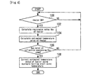
- Fig. 4 is a flowchart that shows a routine executed by the ECU 30 to implement a characteristic correction processing for the heater temperature according to the first embodiment of the present invention. It is assumed that the present routine is to be repeatedly executed for every predetermined control period.
- step 100 it is first determined whether or not the heater 20 is in an ON state (whether or not the energization to the heater 20 is being performed) (step 100). As a result of this, if it is determined that the heater 20 is in the ON state, the resistance value R Htr of the heater 20 is calculated by use of the above described method (step 102). Next, the estimated heater temperature value is calculated in accordance with a relationship between the calculated resistance value R Htr , the resistance value R Htr stored in the ECU30 and the heater temperature (step 104).
- step 106 it is determined whether or not a point of inflection (which comes first after the start of the energization) has appeared on the time change curve of the resistance value R Htr of the heater 20 that is obtained by being repeatedly calculated after the start of the energization to the heater 20 by use of the processing of the step 102 (step 106). As a result of this, if the determination of present step 106 is not established, the processing at or after step 100 is repeatedly performed.
- step 106 If, on the other hand, the aforementioned point of inflection is detected in step 106, that is to say, if it can be judged that the nucleate boiling start point A has come, the heater temperature that is estimated at or after the time of determining that the point of inflection in the resistance value R Htr of the heater 20 (the nucleate boiling start point A) has come is corrected in order to reduce to zero the difference of the estimated heater temperature value at the time of nucleate boiling start with respect to the nucleate boiling start point temperature (step 108). More specifically, the correction according to present step 108 is to be performed continuously during a period in which the energization to the heater 20 is performed after the determination of step 106 is established.
- the nucleate boiling start point A is unambiguously defined with the type of fuel (that is, the property of the fuel) and fuel pressure. For example, if fuel pressure is about 300 kPa when 100 percent alcohol fuel is used, the nucleate boiling start point temperature becomes about 130 degrees C.
- a value stored in advance in the ECU 30 (a value in accordance with a specified fuel type and fuel pressure) is used as the nucleate boiling start point temperature used in present step 108.
- a nucleate boiling start point temperature in accordance with the property of the currently-used fuel that is estimated using an alcohol concentration sensor, an air to fuel ratio sensor or the like is used in present step 108.
- a nucleate boiling start point temperature in accordance with the current fuel pressure that is detected by a fuel pressure sensor is used in present step 108.
- a heater temperature that has been estimated on the basis of the resistance value R Htr after the energization of the heater 20 is stared is immediately replaced with the nucleate boiling start point temperature (in the aforementioned case, 130 degrees C), at the time point of arrival of the nucleate boiling start point A. Further, a heater temperature at or after this time point is estimated using a value at the nucleate boiling start point A as its basis.
- the heater temperature during a period of the energization to the heater 20 at or after this time point is to be calculated as a value that is obtained by reflecting, with respect to a value that is sequentially estimated on the basis of the resistance value R Htr , the aforementioned correction value X.
- the routine shown in Fig. 4 described so far it is judged whether or not the nucleate boiling start point A has arrived on the basis of the behavior of the resistance value R Htr of the heater 20 after the energization is started. Further, when a result of such judgment is positive, a correction of the heater temperature in step 108 is performed.
- Such correction that uses knowledge that the nucleate boiling start point temperature of fuel is unambiguously defined on the basis of fuel property and fuel pressure can properly correct an estimation error of the heater temperature that may be produced due to the above described factors of the variations concerning the hardware, when the nucleate boiling start point A has arrived.
- the estimation accuracy of the heater temperature can be enhanced by such correction processing of the estimated heater temperature value.
- the arrival of the nucleate boiling start point A can be accurately judged using knowledge that a point of inflection appears on the time change curve of the resistance value R Htr of the heater 20 at the time of arrival of the nucleate boiling start point A.
- the heater temperature that is estimated at or after the time of occurrence of the point of inflection in the resistance value R Htr of the heater 20 (the time of determining that the nucleate boiling start point A has arrived) is corrected in order to reduce to zero the difference of the estimated heater temperature value at the time of nucleate boiling start with respect to the nucleate boiling start point temperature.
- a correction method of the heater temperature that is estimated by the heater temperature estimation means in the present invention is not limited to the above described method. More specifically, the correction method of the heater temperature in the present invention is not necessarily limited to the one to accurately reduce to zero the aforementioned difference as with the above described method, and may perform a correction to decrease the difference.
- a fuel injection system that is applied to the present invention is not limited to the aforementioned configuration and may, for example, be one in which a heater for heating fuel supplied to a fuel injection valve is provided outside the fuel injection valve.
- the ECU 30 executes the processing of steps 102 and 104, whereby the "heater temperature estimation means" according to the present invention is realized; and the ECU 30 executes the processing of step 108 when the determination result in step 106 is positive, whereby the "heater temperature correction means" according to the present invention is realized.
Landscapes
- Engineering & Computer Science (AREA)
- Chemical & Material Sciences (AREA)
- Combustion & Propulsion (AREA)
- Mechanical Engineering (AREA)
- General Engineering & Computer Science (AREA)
- Combined Controls Of Internal Combustion Engines (AREA)
- Fuel-Injection Apparatus (AREA)
- Permanent Field Magnets Of Synchronous Machinery (AREA)
- Dc Machiner (AREA)
Abstract
Description
- The present invention relates to a fuel injection system, and more particular to a fuel injection system which includes a heater for heating fuel before being injected from a fuel injection valve.
- So far, for example,
Patent Document 1 discloses a fuel injection system for an internal combustion engine. A fuel injection valve in this conventional system incorporates a heater for heating fuel immediately before being injected. This heater is configured to produce heat by receiving a supply of electric power from a predetermined electric power source. In the aforementioned fuel injection valve, the resistance value of the heater is set to a value within a predetermined range so that the surface temperature of the heater falls within a predetermined temperature range in which a deposit does not adhere. - The temperature of the heater can be estimated on the basis of an unambiguous relationship with the resistance value of the heater. In addition, the resistance value of the heater can be calculated on the basis of electric voltage that is applied to the heater (voltage between both ends of the heater) and electric current that flows through the heater. However, an error may be produced in the estimated temperature value of the heater due to factors of variations concerning its hardware (for example, a variation in the resistance value of the heater, and a variation in the resistance value of a wire harness that supplies the heater with electric power).
-
- Patent Document 1: Japanese Laid-open Patent Application Publication No.
2004-316520 - The present invention has been made to solve the problem as described above, and has its object to provide a fuel injection system that includes a fuel injection valve in which fuel is heated by a heater before being injected and that can favorably improve the estimation accuracy of the heater temperature.
- The present invention is a fuel injection system, which includes a fuel injection valve, a heater, heater temperature estimation means and heater temperature correction means. The fuel injection valve is configured to inject fuel. The heater is configured to receive a supply of electric power from a predetermined power source and heats fuel before the fuel is injected from the fuel injection valve. The heater temperature estimation means estimates the temperature of the heater on the basis of the resistance value of the heater. The heater temperature correction means corrects the temperature of the heater estimated by the heater temperature estimation means so that the difference between the nucleate boiling start point temperature of the fuel and an estimated temperature value of the heater at the time of occurrence of a point of inflection in the resistance value of the heater after energization to the heater is started is reduced.
- When the nucleate boiling start point in which nucleate boiling starts to occur in the fuel that is heated by the heater comes, a point of inflection occurs in the resistance value of the heater. In addition, the nucleate boiling start point temperature of fuel is unambiguously defined on the basis of fuel property and fuel pressure. According to the present invention, the temperature of the heater estimated by the heater temperature estimation means is corrected in order to reduce the difference between the nucleate boiling start point temperature of the fuel and an estimated temperature value of the heater at the time of occurrence of the point of inflection in the resistance value of the heater after energization to the heater is started. This can properly correct an estimation error of the heater temperature that may be produced due to factors of variations concerning the hardware, when the point of inflection in the resistance value of the heater comes, that is to say, when the nucleate boiling start point comes. In addition, the estimation accuracy of the heater temperature can be enhanced by performing such correction processing of the estimated heater temperature value.
- Moreover, the heater temperature correction means in the present invention may provide a correction to reduce the difference with respect to the temperature of the heater estimated by the heater temperature estimation means at or after the time of occurrence of the point of inflection. According to such configuration, the correction for the heater temperature in the present invention is continuously performed with respect to the heater temperature estimated by the heater temperature estimation means at or after the time of occurrence of the aforementioned point of inflection. This can efficiently enhance the estimation accuracy of the heater temperature.
- Furthermore, the correction performed by the heater temperature correction means in the present invention may correct the temperature of the heater estimated by the heater temperature estimation means so as to reduce the difference to zero. According to such configuration, a correction to reduce to zero the aforementioned difference is performed at the time of occurrence of the point of inflection in the resistance value of the heater, as a preferred manner of the correction of the heater temperature in the present invention. This can efficiently enhance the estimation accuracy of the heater temperature.
-
-
Fig. 1 is a diagram for explaining a configuration of the main part of a fuel injection system according to a first embodiment of the present invention; -
Fig. 2 is a diagram showing the boiling curve of fuel; -
Fig. 3 is a diagram illustrating a time change of the resistance value RHtr and temperature of a heater after energization to the heater is started; and -
Fig. 4 is a flowchart of a routine that is executed in the first embodiment of the present invention. -
Fig. 1 is a diagram for explaining a configuration of the main part of a fuel injection system according to a first embodiment of the present invention. - The fuel injection system of the present embodiment includes a
fuel injection valve 10 as shown inFig. 1 . Thefuel injection valve 10 is used to inject fuel with respect to a combustion chamber or an intake passage of an internal combustion engine. Fuel pressurized by a fuel pump (not shown) is supplied to thefuel injection valve 10 from afuel inlet 12. Thefuel injection valve 10 is formed into a substantially cylindrical shape, and the fuel that was supplied from its one end (fuel inlet 12) is injected from anozzle hole 14 formed at the other end after flowing through the inside of thefuel injection valve 10. - A
needle valve 16 is accommodated in thefuel injection valve 10 so as to be movable in its axial direction. Theneedle valve 16 is driven by an electro-magnetic drive unit 18 to move in the axial direction and, as a result, thenozzle hole 14 opens and closes. The electro-magnetic drive unit 18 includes, as main constituent parts, an electro-magnetic coil 18a, an armature 18b and acompression spring 18c. - Further, a
heater 20 is incorporated into thefuel injection valve 10 at a location at which theheater 20 comes into contact with fuel that flows through a fuel flow passage that is formed into thefuel injection valve 10. Theheater 20 receives a supply of electric power from a predetermined electric power source (for example, a battery of a vehicle in which an internal combustion engine having thefuel injection valve 10 is mounted), and includes a heat resistive element having characteristics (PTC (Positive Temperature Coefficient)) that when its temperature increases, its electric resistance value increases. - The system shown in
Fig. 1 includes an Electronic Control Unit (ECU) 30. The ECU 30 is configured as a known microcomputer in which a ROM, a RAM, a CPU, input ports and output ports that are not shown are connected with one another by interactive buses. The ECU 30 uses the electric power source, such as the aforementioned battery, to start or stop the energization to aterminal 22 of thefuel injection valve 10 and thereby controls a time period of the energization to thefuel injection valve 10. In addition, the ECU 30 uses the electric power source, such as the aforementioned battery, to pass electric current through theheater 20 via a conductingterminal 24 over a predetermined time period and thereby supplies a predetermined amount of electric power. More specifically, theECU 30 reads signals of various sensors (not shown) that detect the operational state of the internal combustion engine (for example, an engine speed, intake air amount and cooling water temperature), and controls the energization of thefuel injection valve 10 and the energization of theheater 20 in accordance with predetermined programs. - As described so far, the
fuel injection valve 10 of the present embodiment is configured so that fuel is heated by the built-inheater 20 immediately before being injected from thenozzle hole 14. For example, theECU 30 starts the energization of theheater 20 when detecting an operation of an ignition switch (not shown) to an ON state at the time of a cold start of the internal combustion engine. If fuel injection by thefuel injection valve 10 is performed in a state in which such energization to theheater 20 has been made, fuel that flows through the inside of thefuel injection valve 10 is injected from thenozzle hole 14 after the fuel is heated by theheater 20. Injecting the heated fuel from thenozzle hole 14 can boost fuel atomization (nebulization). This makes it possible to sufficiently reduce exhaust emissions. - Next, an estimation method for the heater temperature based on the resistance value RHTR of the
heater 20 will be described. - To the
heater 20, a drive voltage (herein, a battery voltage as one example) is applied via a wire harness (electric wires) that are not shown. It is assumed that a part of the wire harness includes the aforementionedconducting terminal 24. TheECU 30 is configured so as to be able to detect two inputs, that is, the battery voltage and a voltage drop VWH in the wire harness as a whole. The electric resistance value of the wire harness as a whole is referred to as RWH. The electric resistance value RWH itself is stored in theECU 30 as a design value. TheECU 30 use the electric resistance value RWH as a so-called shunt resistance, and calculates electric current I that flows through theheater 20 on the basis of the voltage drop VWH. - Furthermore, the
ECU 30 calculates the resistance value of the heater 20 (the internal resistance value) RHtr on the basis of the calculated electric current value I and the electric voltage VHtr between both ends of the heater 20 (the value obtained by subtracting the voltage drop VWH from the battery voltage). There exists an unambiguous relationship between the resistance value RHtr and temperature of theheater 20. TheECU 30 stores such relationship. Therefore, theECU 30 can calculate the estimated temperature value of the heater on the basis of such relationship and the calculated resistance value RHtr of theheater 20. -
Fig. 2 is a diagram showing the boiling curve of fuel. More specifically,Fig. 2 represents boiling phenomena of fuel that is liquid, with a relationship between the heat flux between a heat transfer surface (the surface of the heater 20) and fuel, and the difference (degree of superheat) of the temperature of the heat transfer surface (the surface temperature of the heater 20) with respect to the saturated temperature (boiling point) of liquid. - When fuel is heated by the
heater 20 incorporated into thefuel injection valve 10, the state of boiling of the fuel changes in accordance with the degree of superheat (the difference between the surface temperature of theheater 20 and the boiling point of the fuel). Specifically, as a result of the heating of fuel by theheater 20 progressing in a non boiling range with natural convection at the initial stage of the heating (a range indicated "Free Convection" inFig. 2 ), the temperature of the heat transfer surface reaches the nucleate boiling start point A and a nucleate boiling range is reached. When entering the nucleate boiling range, heat flux rapidly increases as shown inFig. 2 . When the heat flux exceeds the nucleate boiling start point A, the heat supplied to theheater 20 becomes easy to be transferred to fuel. Because of this, in order to efficiently warm up the fuel using less energy, it can be said what is most effective is to use the nucleate boiling range in which heat flux is large. In addition, in order to efficiently use the nucleate boiling range, it is required to control the temperature (surface temperature) of theheater 20 within a temperature range in which nucleate boiling occurs. - According to the above described estimation method, the estimated temperature value of the heater can be calculated on the basis of the resistance value RHtr of the
heater 20. However, the enerzation path of theheater 20 has factors of variations concerning its hardware (such as a variation in the resistance value RHtr of theheater 20 and a variation in the resistance value RWH in the aforementioned wire harness). Due to such factors of the variation, a variation may be arisen to the electric current I or the resistance value RHtr of theheater 20 calculated as described above. As a result of this, an error may be arisen to the estimated value of the heater temperature. - To prevent the
heater 20 from being overheated when controlling the heater temperature in order to use the nucleate boiling region, it is needed to assume a situation in which the actual heater temperature becomes higher than the estimated value due to an estimation error as described above. As a result, it is needed to control the heater temperature within a lower temperature range, and therefore, it becomes difficult to use the nucleate boiling region wider (up to nearly the upper limit). Accordingly, in the present embodiment, the following correction is made with respect to the heater temperature that is estimated using the above described method during use of theheater 20 in order to increase the estimation accuracy of the heater temperature. -
Fig. 3 is a diagram illustrating a time change of the resistance value RHtr and temperature of theheater 20 after the energization to theheater 20 is started. - A time point tA in
Fig. 3 shows a timing at which the nucleate boiling start point (Onset of Nucleate Boiling) A comes after the energization to theheater 20 is started. As described above, if heat flux increases beyond the nucleate boiling start point A, the heat that theheater 20 received becomes easy to be transferred to fuel. As a result of this, an increase in temperature of theheater 20 slows down (stagnates) during a nucleate boiling occurrence period after the time point tA comes, as shown inFig. 3 . In addition, when the time point tA in which such stagnation (plateau) of a temperature increase in theheater 20 occurs comes, as shown inFig. 3 , a point of inflection appears on a time change curve of the resistance value RHtr of theheater 20 after the energization to theheater 20 is started. - Accordingly, in the present embodiment, it is determined that when a point of inflection (first point of inflection) on a time change curve of the resistance value RHtr calculated for estimation of the heater temperature is detected after the energization to the
heater 20 is started, the nucleate boiling start point A in which nucleate boiling starts to occur in the fuel heated by theheater 20 has come. The estimated value of the heater temperature at the time of this determination is herein referred to as an "estimated heater temperature value at the time of nucleate boiling start". In the present embodiment, when the aforementioned determination is made, the heater temperature that is estimated at or after the time of occurrence of the point of inflection in the resistance value RHtr of the heater 20 (the time of determining that the nucleate boiling start point A has come) is corrected in order to reduce to zero the difference (deviation amount) of the estimated heater temperature value at the time of nucleate boiling start with respect to the temperature of fuel at the nucleate boiling start point A (hereinafter, referred to as a "nucleate boiling start point temperature"). -
Fig. 4 is a flowchart that shows a routine executed by theECU 30 to implement a characteristic correction processing for the heater temperature according to the first embodiment of the present invention. It is assumed that the present routine is to be repeatedly executed for every predetermined control period. - As shown in
Fig. 4 , it is first determined whether or not theheater 20 is in an ON state (whether or not the energization to theheater 20 is being performed) (step 100). As a result of this, if it is determined that theheater 20 is in the ON state, the resistance value RHtr of theheater 20 is calculated by use of the above described method (step 102). Next, the estimated heater temperature value is calculated in accordance with a relationship between the calculated resistance value RHtr, the resistance value RHtr stored in the ECU30 and the heater temperature (step 104). - Next, it is determined whether or not a point of inflection (which comes first after the start of the energization) has appeared on the time change curve of the resistance value RHtr of the
heater 20 that is obtained by being repeatedly calculated after the start of the energization to theheater 20 by use of the processing of the step 102 (step 106). As a result of this, if the determination ofpresent step 106 is not established, the processing at or afterstep 100 is repeatedly performed. - If, on the other hand, the aforementioned point of inflection is detected in
step 106, that is to say, if it can be judged that the nucleate boiling start point A has come, the heater temperature that is estimated at or after the time of determining that the point of inflection in the resistance value RHtr of the heater 20 (the nucleate boiling start point A) has come is corrected in order to reduce to zero the difference of the estimated heater temperature value at the time of nucleate boiling start with respect to the nucleate boiling start point temperature (step 108). More specifically, the correction according topresent step 108 is to be performed continuously during a period in which the energization to theheater 20 is performed after the determination ofstep 106 is established. - The nucleate boiling start point A is unambiguously defined with the type of fuel (that is, the property of the fuel) and fuel pressure. For example, if fuel pressure is about 300 kPa when 100 percent alcohol fuel is used, the nucleate boiling start point temperature becomes about 130 degrees C.
- In a case of an internal combustion engine in which the used fuel is fixed by a specific fuel (for example, gasoline) and fuel pressure is set to a predetermined constant value in accordance with the specification of the internal combustion engine, a value stored in advance in the ECU 30 (a value in accordance with a specified fuel type and fuel pressure) is used as the nucleate boiling start point temperature used in
present step 108. On the other hand, in a case, for example, of an internal combustion engine mounted in a vehicle in which the property of fuel in a fuel tank may change in accordance with a manner of fueling, such as an internal combustion engine that uses a blended fuel of hydrocarbon fuel and alcohol fuel within an arbitrary blend ratio range, a nucleate boiling start point temperature in accordance with the property of the currently-used fuel that is estimated using an alcohol concentration sensor, an air to fuel ratio sensor or the like is used inpresent step 108. In addition, in a case of an internal combustion engine capable of changing fuel pressure during operation, a nucleate boiling start point temperature in accordance with the current fuel pressure that is detected by a fuel pressure sensor is used inpresent step 108. - According to the correction of the heater temperature in
present step 108, a heater temperature that has been estimated on the basis of the resistance value RHtr after the energization of theheater 20 is stared is immediately replaced with the nucleate boiling start point temperature (in the aforementioned case, 130 degrees C), at the time point of arrival of the nucleate boiling start point A. Further, a heater temperature at or after this time point is estimated using a value at the nucleate boiling start point A as its basis. More specifically, if it is assumed that a correction amount necessary for correcting, to the nucleate boiling start point temperature, the estimated heater temperature value at the time point of arrival of the nucleate boiling start point A is X, the heater temperature during a period of the energization to theheater 20 at or after this time point is to be calculated as a value that is obtained by reflecting, with respect to a value that is sequentially estimated on the basis of the resistance value RHtr, the aforementioned correction value X. - According to the routine shown in
Fig. 4 described so far, it is judged whether or not the nucleate boiling start point A has arrived on the basis of the behavior of the resistance value RHtr of theheater 20 after the energization is started. Further, when a result of such judgment is positive, a correction of the heater temperature instep 108 is performed. Such correction that uses knowledge that the nucleate boiling start point temperature of fuel is unambiguously defined on the basis of fuel property and fuel pressure can properly correct an estimation error of the heater temperature that may be produced due to the above described factors of the variations concerning the hardware, when the nucleate boiling start point A has arrived. In addition, the estimation accuracy of the heater temperature can be enhanced by such correction processing of the estimated heater temperature value. Therefore, fuel can be effectively heated by theheater 20 owing to wide use (up to nearly the upper limit) of the nucleate boiling region. As a result of that, the atomization (nebulization) of fuel can be effectively boosted, and therefore, exhaust emission can be efficiently decreased. - Furthermore, according to the above described routine, the arrival of the nucleate boiling start point A can be accurately judged using knowledge that a point of inflection appears on the time change curve of the resistance value RHtr of the
heater 20 at the time of arrival of the nucleate boiling start point A. - Incidentally, in the first embodiment, which has been described above, when the point of inflection in the resistance value RHtr of the
heater 20 occurs (when it is determined that the nucleate boiling start point A has arrived), the heater temperature that is estimated at or after the time of occurrence of the point of inflection in the resistance value RHtr of the heater 20 (the time of determining that the nucleate boiling start point A has arrived) is corrected in order to reduce to zero the difference of the estimated heater temperature value at the time of nucleate boiling start with respect to the nucleate boiling start point temperature. However, a correction method of the heater temperature that is estimated by the heater temperature estimation means in the present invention is not limited to the above described method. More specifically, the correction method of the heater temperature in the present invention is not necessarily limited to the one to accurately reduce to zero the aforementioned difference as with the above described method, and may perform a correction to decrease the difference. - Moreover, in the above described first embodiment, a description was made by taking, as one example, a
fuel injection valve 10 into which theheater 20 to heat fuel immediately before being injected is incorporated. However, a fuel injection system that is applied to the present invention is not limited to the aforementioned configuration and may, for example, be one in which a heater for heating fuel supplied to a fuel injection valve is provided outside the fuel injection valve. - It is noted that in the first embodiment, which has been described above, the
ECU 30 executes the processing ofsteps ECU 30 executes the processing ofstep 108 when the determination result instep 106 is positive, whereby the "heater temperature correction means" according to the present invention is realized. -
- 10
- fuel injection valve
- 12
- fuel inlet
- 14
- nozzle hole
- 16
- needle valve
- 18
- electro-magnetic drive unit
- 18a
- electro-magnetic coil of electro-magnetic drive unit
- 18b
- armature of electro-magnetic drive unit
- 18c
- compression spring of electro-magnetic drive unit
- 20
- heater
- 22
- terminal
- 24
- conducting terminal
- 30
- Electronic Control Unit (ECU)
Claims (3)
- A fuel injection system, comprising:a fuel injection valve configured to inject fuel;a heater configured to receive a supply of electric power from a predetermined power source and heats fuel before the fuel is injected from the fuel injection valve;heater temperature estimation means for estimating a temperature of the heater on a basis of a resistance value of the heater; andheater temperature correction means for correcting the temperature of the heater estimated by the heater temperature estimation means so that a difference between a nucleate boiling start point temperature of the fuel and an estimated temperature value of the heater at a time of occurrence of a point of inflection in the resistance value of the heater after energization to the heater is started is reduced.
- The fuel injection system according to claim 1,
wherein, to reduce the difference, the heater temperature correction means provides a correction to reduce the difference with respect to the temperature of the heater estimated by the heater temperature estimation means at or after the time of occurrence of the point of inflection. - The fuel injection system according to claim 1 or 2,
wherein the heater temperature correction means corrects the temperature of the heater estimated by the heater temperature estimation means so as to reduce the difference to zero.
Applications Claiming Priority (1)
| Application Number | Priority Date | Filing Date | Title |
|---|---|---|---|
| PCT/JP2012/068861 WO2014016920A1 (en) | 2012-07-25 | 2012-07-25 | Fuel injector device |
Publications (3)
| Publication Number | Publication Date |
|---|---|
| EP2878799A1 true EP2878799A1 (en) | 2015-06-03 |
| EP2878799A4 EP2878799A4 (en) | 2015-07-29 |
| EP2878799B1 EP2878799B1 (en) | 2017-06-21 |
Family
ID=49996756
Family Applications (1)
| Application Number | Title | Priority Date | Filing Date |
|---|---|---|---|
| EP12881776.4A Not-in-force EP2878799B1 (en) | 2012-07-25 | 2012-07-25 | Fuel injector device |
Country Status (6)
| Country | Link |
|---|---|
| US (1) | US9784227B2 (en) |
| EP (1) | EP2878799B1 (en) |
| JP (1) | JP6003985B2 (en) |
| CN (1) | CN104508290B (en) |
| BR (1) | BR112015001356B1 (en) |
| WO (1) | WO2014016920A1 (en) |
Cited By (1)
| Publication number | Priority date | Publication date | Assignee | Title |
|---|---|---|---|---|
| WO2024186537A1 (en) * | 2023-03-09 | 2024-09-12 | Phinia Jersey Holdings Llc | Ethanol detection with heated fuel injector in flexible fuel vehicles |
Families Citing this family (4)
| Publication number | Priority date | Publication date | Assignee | Title |
|---|---|---|---|---|
| JP6497275B2 (en) * | 2015-08-26 | 2019-04-10 | 株式会社デンソー | Electronic control unit |
| DE102016105048A1 (en) * | 2016-03-18 | 2017-09-21 | Volkswagen Aktiengesellschaft | Internal combustion engine and method for operating an internal combustion engine |
| KR101827131B1 (en) * | 2016-07-15 | 2018-02-07 | 현대자동차주식회사 | Apparatus for heating flex fuel of vehicle and method thereof |
| JP6642361B2 (en) * | 2016-09-23 | 2020-02-05 | 株式会社デンソー | Heater drive |
Family Cites Families (22)
| Publication number | Priority date | Publication date | Assignee | Title |
|---|---|---|---|---|
| US5649515A (en) * | 1991-07-18 | 1997-07-22 | Hermann-Frank Muller | Diesel fuel preheater for engines |
| JPH0988740A (en) * | 1995-09-27 | 1997-03-31 | Toyota Autom Loom Works Ltd | Fuel gasification device and heater for fuel gasification |
| JP4147659B2 (en) * | 1998-12-24 | 2008-09-10 | トヨタ自動車株式会社 | Control device for reformer |
| DE19952344C2 (en) | 1999-10-29 | 2002-01-31 | Siemens Ag | Method for determining the injection period in an internal combustion engine |
| JP2004316520A (en) | 2003-04-15 | 2004-11-11 | Denso Corp | Fuel injection device |
| JP4069911B2 (en) * | 2004-08-06 | 2008-04-02 | 株式会社日立製作所 | Heated fuel injection valve |
| US7370610B2 (en) * | 2006-02-17 | 2008-05-13 | The Board Of Regents, The University Of Texas System | On-board fuel fractionation system and methods to generate an engine starting fuel |
| JP2007231757A (en) * | 2006-02-28 | 2007-09-13 | Toyota Motor Corp | Control device for internal combustion engine and control method for internal combustion engine |
| US7481376B2 (en) * | 2006-03-17 | 2009-01-27 | Continental Automotive Systems Us, Inc. | Variable inductive heated injector |
| US8967124B2 (en) * | 2006-03-21 | 2015-03-03 | Continental Automotive Systems, Inc. | Inductive heated injector using voltage transformer technology |
| WO2007123632A1 (en) * | 2006-03-27 | 2007-11-01 | Continental Automotive Systems Us, Inc. | Inductive heated injector using additional coil |
| DE102006053808B4 (en) * | 2006-11-15 | 2021-01-07 | Robert Bosch Gmbh | Method for determining the temperature of a measuring probe |
| US7798131B2 (en) * | 2007-03-16 | 2010-09-21 | Continental Automotive Systems Us, Inc. | Automotive modular inductive heated injector and system |
| US7766254B2 (en) * | 2008-05-30 | 2010-08-03 | Delphi Technologies, Inc. | Heated fuel injector |
| US8342425B2 (en) * | 2008-12-03 | 2013-01-01 | Continental Automotive Systems Us, Inc. | Multi-point low pressure inductively heated fuel injector with heat exchanger |
| US8884198B2 (en) * | 2010-01-22 | 2014-11-11 | Continental Automotive Systems, Inc. | Parametric temperature regulation of induction heated load |
| DE102010022242A1 (en) * | 2010-05-20 | 2011-11-24 | Borgwarner Beru Systems Gmbh | Method of operating a diesel fuel filter heater |
| JP5560131B2 (en) | 2010-07-27 | 2014-07-23 | トヨタ自動車株式会社 | Fuel supply device |
| US8783281B2 (en) * | 2010-09-13 | 2014-07-22 | GM Global Technology Operations LLC | Fuel tank temperature and pressure management via selective extraction of liquid fuel and fuel vapor |
| CN104316210B (en) * | 2010-10-04 | 2017-10-13 | 株式会社理光 | Electrical equipment, integrated circuit and equipment |
| US9074566B2 (en) * | 2011-04-22 | 2015-07-07 | Continental Automotive Systems, Inc. | Variable spray injector with nucleate boiling heat exchanger |
| JP5917836B2 (en) * | 2011-06-07 | 2016-05-18 | 株式会社日本自動車部品総合研究所 | Fuel supply device for internal combustion engine |
-
2012
- 2012-07-25 US US14/416,756 patent/US9784227B2/en active Active
- 2012-07-25 WO PCT/JP2012/068861 patent/WO2014016920A1/en not_active Ceased
- 2012-07-25 CN CN201280074888.2A patent/CN104508290B/en not_active Expired - Fee Related
- 2012-07-25 EP EP12881776.4A patent/EP2878799B1/en not_active Not-in-force
- 2012-07-25 JP JP2014526655A patent/JP6003985B2/en not_active Expired - Fee Related
- 2012-07-25 BR BR112015001356-2A patent/BR112015001356B1/en not_active IP Right Cessation
Cited By (1)
| Publication number | Priority date | Publication date | Assignee | Title |
|---|---|---|---|---|
| WO2024186537A1 (en) * | 2023-03-09 | 2024-09-12 | Phinia Jersey Holdings Llc | Ethanol detection with heated fuel injector in flexible fuel vehicles |
Also Published As
| Publication number | Publication date |
|---|---|
| BR112015001356A2 (en) | 2017-07-04 |
| BR112015001356B1 (en) | 2021-06-08 |
| CN104508290B (en) | 2017-04-26 |
| JPWO2014016920A1 (en) | 2016-07-07 |
| CN104508290A (en) | 2015-04-08 |
| JP6003985B2 (en) | 2016-10-05 |
| WO2014016920A1 (en) | 2014-01-30 |
| EP2878799A4 (en) | 2015-07-29 |
| EP2878799B1 (en) | 2017-06-21 |
| US9784227B2 (en) | 2017-10-10 |
| US20150219050A1 (en) | 2015-08-06 |
Similar Documents
| Publication | Publication Date | Title |
|---|---|---|
| CN102713219B (en) | For trying to achieve the method and apparatus of the fuel pressure on straight spray valve | |
| EP2878799B1 (en) | Fuel injector device | |
| EP2578862A1 (en) | Fault diagnosis device for temperature sensor | |
| CN102770643B (en) | Abnormality detection device for fuel property detection device | |
| CN103912429A (en) | Using Resistance Equivalent To Estimate Temperature Of Fuel-injector Heater | |
| US8362405B2 (en) | Heater controller of exhaust gas sensor | |
| JP2010038024A (en) | Fuel temperature control device of internal combustion engine | |
| US8397697B2 (en) | Method and device for operating an injection valve | |
| CN106795826A (en) | The control device of internal combustion engine | |
| JP4941391B2 (en) | Heating element control device | |
| JP2009185676A (en) | Fuel supply device for internal combustion engine | |
| JP5429023B2 (en) | Control device for internal combustion engine | |
| JP7428094B2 (en) | injection control device | |
| JP5862466B2 (en) | Fuel injection control device and fuel injection control method | |
| CN110446843B (en) | Control device for internal combustion engine | |
| WO2024141558A1 (en) | Method for injecting a fluid and injector system for a vehicle engine | |
| JP2016217263A (en) | Control device for internal combustion engine | |
| RU2719617C2 (en) | Method (versions) and system for controlling operation of engine based on temperature of exhaust gases | |
| KR101544795B1 (en) | Method for compensating fuel injection amount of vehicle engine | |
| JP4333376B2 (en) | Oxygen sensor control device | |
| JP2012505336A (en) | Method and control apparatus for controlling a fuel injector | |
| JP2008501087A (en) | Operation method and control apparatus for internal combustion engine | |
| JP2010014036A (en) | Internal combustion engine stop time estimation device | |
| JP2013002379A (en) | Injector diagnostic method of gas fuel supply system, and device thereof | |
| JP2007170327A (en) | Fuel supply device for internal combustion engine |
Legal Events
| Date | Code | Title | Description |
|---|---|---|---|
| PUAI | Public reference made under article 153(3) epc to a published international application that has entered the european phase |
Free format text: ORIGINAL CODE: 0009012 |
|
| 17P | Request for examination filed |
Effective date: 20150113 |
|
| AK | Designated contracting states |
Kind code of ref document: A1 Designated state(s): AL AT BE BG CH CY CZ DE DK EE ES FI FR GB GR HR HU IE IS IT LI LT LU LV MC MK MT NL NO PL PT RO RS SE SI SK SM TR |
|
| AX | Request for extension of the european patent |
Extension state: BA ME |
|
| RA4 | Supplementary search report drawn up and despatched (corrected) |
Effective date: 20150625 |
|
| RIC1 | Information provided on ipc code assigned before grant |
Ipc: F02M 51/06 20060101ALI20150619BHEP Ipc: F02M 31/125 20060101AFI20150619BHEP Ipc: F02M 53/04 20060101ALI20150619BHEP Ipc: F02M 53/02 20060101ALI20150619BHEP Ipc: F02M 53/06 20060101ALI20150619BHEP |
|
| DAX | Request for extension of the european patent (deleted) | ||
| GRAP | Despatch of communication of intention to grant a patent |
Free format text: ORIGINAL CODE: EPIDOSNIGR1 |
|
| INTG | Intention to grant announced |
Effective date: 20170130 |
|
| GRAS | Grant fee paid |
Free format text: ORIGINAL CODE: EPIDOSNIGR3 |
|
| GRAA | (expected) grant |
Free format text: ORIGINAL CODE: 0009210 |
|
| AK | Designated contracting states |
Kind code of ref document: B1 Designated state(s): AL AT BE BG CH CY CZ DE DK EE ES FI FR GB GR HR HU IE IS IT LI LT LU LV MC MK MT NL NO PL PT RO RS SE SI SK SM TR |
|
| REG | Reference to a national code |
Ref country code: GB Ref legal event code: FG4D |
|
| REG | Reference to a national code |
Ref country code: CH Ref legal event code: EP |
|
| REG | Reference to a national code |
Ref country code: IE Ref legal event code: FG4D |
|
| REG | Reference to a national code |
Ref country code: AT Ref legal event code: REF Ref document number: 903185 Country of ref document: AT Kind code of ref document: T Effective date: 20170715 |
|
| REG | Reference to a national code |
Ref country code: FR Ref legal event code: PLFP Year of fee payment: 6 |
|
| REG | Reference to a national code |
Ref country code: DE Ref legal event code: R096 Ref document number: 602012033854 Country of ref document: DE |
|
| REG | Reference to a national code |
Ref country code: NL Ref legal event code: MP Effective date: 20170621 |
|
| PG25 | Lapsed in a contracting state [announced via postgrant information from national office to epo] |
Ref country code: LT Free format text: LAPSE BECAUSE OF FAILURE TO SUBMIT A TRANSLATION OF THE DESCRIPTION OR TO PAY THE FEE WITHIN THE PRESCRIBED TIME-LIMIT Effective date: 20170621 Ref country code: HR Free format text: LAPSE BECAUSE OF FAILURE TO SUBMIT A TRANSLATION OF THE DESCRIPTION OR TO PAY THE FEE WITHIN THE PRESCRIBED TIME-LIMIT Effective date: 20170621 Ref country code: NO Free format text: LAPSE BECAUSE OF FAILURE TO SUBMIT A TRANSLATION OF THE DESCRIPTION OR TO PAY THE FEE WITHIN THE PRESCRIBED TIME-LIMIT Effective date: 20170921 Ref country code: GR Free format text: LAPSE BECAUSE OF FAILURE TO SUBMIT A TRANSLATION OF THE DESCRIPTION OR TO PAY THE FEE WITHIN THE PRESCRIBED TIME-LIMIT Effective date: 20170922 Ref country code: FI Free format text: LAPSE BECAUSE OF FAILURE TO SUBMIT A TRANSLATION OF THE DESCRIPTION OR TO PAY THE FEE WITHIN THE PRESCRIBED TIME-LIMIT Effective date: 20170621 |
|
| REG | Reference to a national code |
Ref country code: LT Ref legal event code: MG4D |
|
| REG | Reference to a national code |
Ref country code: AT Ref legal event code: MK05 Ref document number: 903185 Country of ref document: AT Kind code of ref document: T Effective date: 20170621 |
|
| PG25 | Lapsed in a contracting state [announced via postgrant information from national office to epo] |
Ref country code: BG Free format text: LAPSE BECAUSE OF FAILURE TO SUBMIT A TRANSLATION OF THE DESCRIPTION OR TO PAY THE FEE WITHIN THE PRESCRIBED TIME-LIMIT Effective date: 20170921 Ref country code: RS Free format text: LAPSE BECAUSE OF FAILURE TO SUBMIT A TRANSLATION OF THE DESCRIPTION OR TO PAY THE FEE WITHIN THE PRESCRIBED TIME-LIMIT Effective date: 20170621 Ref country code: NL Free format text: LAPSE BECAUSE OF FAILURE TO SUBMIT A TRANSLATION OF THE DESCRIPTION OR TO PAY THE FEE WITHIN THE PRESCRIBED TIME-LIMIT Effective date: 20170621 Ref country code: LV Free format text: LAPSE BECAUSE OF FAILURE TO SUBMIT A TRANSLATION OF THE DESCRIPTION OR TO PAY THE FEE WITHIN THE PRESCRIBED TIME-LIMIT Effective date: 20170621 Ref country code: SE Free format text: LAPSE BECAUSE OF FAILURE TO SUBMIT A TRANSLATION OF THE DESCRIPTION OR TO PAY THE FEE WITHIN THE PRESCRIBED TIME-LIMIT Effective date: 20170621 |
|
| PG25 | Lapsed in a contracting state [announced via postgrant information from national office to epo] |
Ref country code: RO Free format text: LAPSE BECAUSE OF FAILURE TO SUBMIT A TRANSLATION OF THE DESCRIPTION OR TO PAY THE FEE WITHIN THE PRESCRIBED TIME-LIMIT Effective date: 20170621 Ref country code: AT Free format text: LAPSE BECAUSE OF FAILURE TO SUBMIT A TRANSLATION OF THE DESCRIPTION OR TO PAY THE FEE WITHIN THE PRESCRIBED TIME-LIMIT Effective date: 20170621 Ref country code: SK Free format text: LAPSE BECAUSE OF FAILURE TO SUBMIT A TRANSLATION OF THE DESCRIPTION OR TO PAY THE FEE WITHIN THE PRESCRIBED TIME-LIMIT Effective date: 20170621 Ref country code: CZ Free format text: LAPSE BECAUSE OF FAILURE TO SUBMIT A TRANSLATION OF THE DESCRIPTION OR TO PAY THE FEE WITHIN THE PRESCRIBED TIME-LIMIT Effective date: 20170621 Ref country code: EE Free format text: LAPSE BECAUSE OF FAILURE TO SUBMIT A TRANSLATION OF THE DESCRIPTION OR TO PAY THE FEE WITHIN THE PRESCRIBED TIME-LIMIT Effective date: 20170621 |
|
| PG25 | Lapsed in a contracting state [announced via postgrant information from national office to epo] |
Ref country code: ES Free format text: LAPSE BECAUSE OF FAILURE TO SUBMIT A TRANSLATION OF THE DESCRIPTION OR TO PAY THE FEE WITHIN THE PRESCRIBED TIME-LIMIT Effective date: 20170621 Ref country code: SM Free format text: LAPSE BECAUSE OF FAILURE TO SUBMIT A TRANSLATION OF THE DESCRIPTION OR TO PAY THE FEE WITHIN THE PRESCRIBED TIME-LIMIT Effective date: 20170621 Ref country code: IS Free format text: LAPSE BECAUSE OF FAILURE TO SUBMIT A TRANSLATION OF THE DESCRIPTION OR TO PAY THE FEE WITHIN THE PRESCRIBED TIME-LIMIT Effective date: 20171021 Ref country code: PL Free format text: LAPSE BECAUSE OF FAILURE TO SUBMIT A TRANSLATION OF THE DESCRIPTION OR TO PAY THE FEE WITHIN THE PRESCRIBED TIME-LIMIT Effective date: 20170621 |
|
| REG | Reference to a national code |
Ref country code: CH Ref legal event code: PL |
|
| REG | Reference to a national code |
Ref country code: DE Ref legal event code: R097 Ref document number: 602012033854 Country of ref document: DE |
|
| PG25 | Lapsed in a contracting state [announced via postgrant information from national office to epo] |
Ref country code: MC Free format text: LAPSE BECAUSE OF FAILURE TO SUBMIT A TRANSLATION OF THE DESCRIPTION OR TO PAY THE FEE WITHIN THE PRESCRIBED TIME-LIMIT Effective date: 20170621 |
|
| REG | Reference to a national code |
Ref country code: IE Ref legal event code: MM4A |
|
| REG | Reference to a national code |
Ref country code: DE Ref legal event code: R084 Ref document number: 602012033854 Country of ref document: DE |
|
| PLBE | No opposition filed within time limit |
Free format text: ORIGINAL CODE: 0009261 |
|
| STAA | Information on the status of an ep patent application or granted ep patent |
Free format text: STATUS: NO OPPOSITION FILED WITHIN TIME LIMIT |
|
| PG25 | Lapsed in a contracting state [announced via postgrant information from national office to epo] |
Ref country code: CH Free format text: LAPSE BECAUSE OF NON-PAYMENT OF DUE FEES Effective date: 20170731 Ref country code: DK Free format text: LAPSE BECAUSE OF FAILURE TO SUBMIT A TRANSLATION OF THE DESCRIPTION OR TO PAY THE FEE WITHIN THE PRESCRIBED TIME-LIMIT Effective date: 20170621 Ref country code: IE Free format text: LAPSE BECAUSE OF NON-PAYMENT OF DUE FEES Effective date: 20170725 Ref country code: LI Free format text: LAPSE BECAUSE OF NON-PAYMENT OF DUE FEES Effective date: 20170731 |
|
| REG | Reference to a national code |
Ref country code: GB Ref legal event code: 746 Effective date: 20180420 |
|
| 26N | No opposition filed |
Effective date: 20180322 |
|
| REG | Reference to a national code |
Ref country code: BE Ref legal event code: MM Effective date: 20170731 |
|
| REG | Reference to a national code |
Ref country code: FR Ref legal event code: PLFP Year of fee payment: 7 |
|
| PG25 | Lapsed in a contracting state [announced via postgrant information from national office to epo] |
Ref country code: LU Free format text: LAPSE BECAUSE OF NON-PAYMENT OF DUE FEES Effective date: 20170725 |
|
| PG25 | Lapsed in a contracting state [announced via postgrant information from national office to epo] |
Ref country code: BE Free format text: LAPSE BECAUSE OF NON-PAYMENT OF DUE FEES Effective date: 20170731 Ref country code: SI Free format text: LAPSE BECAUSE OF FAILURE TO SUBMIT A TRANSLATION OF THE DESCRIPTION OR TO PAY THE FEE WITHIN THE PRESCRIBED TIME-LIMIT Effective date: 20170621 |
|
| PG25 | Lapsed in a contracting state [announced via postgrant information from national office to epo] |
Ref country code: MT Free format text: LAPSE BECAUSE OF NON-PAYMENT OF DUE FEES Effective date: 20170725 |
|
| PG25 | Lapsed in a contracting state [announced via postgrant information from national office to epo] |
Ref country code: HU Free format text: LAPSE BECAUSE OF FAILURE TO SUBMIT A TRANSLATION OF THE DESCRIPTION OR TO PAY THE FEE WITHIN THE PRESCRIBED TIME-LIMIT; INVALID AB INITIO Effective date: 20120725 |
|
| PG25 | Lapsed in a contracting state [announced via postgrant information from national office to epo] |
Ref country code: CY Free format text: LAPSE BECAUSE OF FAILURE TO SUBMIT A TRANSLATION OF THE DESCRIPTION OR TO PAY THE FEE WITHIN THE PRESCRIBED TIME-LIMIT Effective date: 20170621 |
|
| PG25 | Lapsed in a contracting state [announced via postgrant information from national office to epo] |
Ref country code: MK Free format text: LAPSE BECAUSE OF FAILURE TO SUBMIT A TRANSLATION OF THE DESCRIPTION OR TO PAY THE FEE WITHIN THE PRESCRIBED TIME-LIMIT Effective date: 20170621 |
|
| PG25 | Lapsed in a contracting state [announced via postgrant information from national office to epo] |
Ref country code: TR Free format text: LAPSE BECAUSE OF FAILURE TO SUBMIT A TRANSLATION OF THE DESCRIPTION OR TO PAY THE FEE WITHIN THE PRESCRIBED TIME-LIMIT Effective date: 20170621 |
|
| PG25 | Lapsed in a contracting state [announced via postgrant information from national office to epo] |
Ref country code: PT Free format text: LAPSE BECAUSE OF FAILURE TO SUBMIT A TRANSLATION OF THE DESCRIPTION OR TO PAY THE FEE WITHIN THE PRESCRIBED TIME-LIMIT Effective date: 20170621 |
|
| PG25 | Lapsed in a contracting state [announced via postgrant information from national office to epo] |
Ref country code: AL Free format text: LAPSE BECAUSE OF FAILURE TO SUBMIT A TRANSLATION OF THE DESCRIPTION OR TO PAY THE FEE WITHIN THE PRESCRIBED TIME-LIMIT Effective date: 20170621 |
|
| PGFP | Annual fee paid to national office [announced via postgrant information from national office to epo] |
Ref country code: IT Payment date: 20220613 Year of fee payment: 11 Ref country code: GB Payment date: 20220606 Year of fee payment: 11 |
|
| PGFP | Annual fee paid to national office [announced via postgrant information from national office to epo] |
Ref country code: FR Payment date: 20220609 Year of fee payment: 11 |
|
| PGFP | Annual fee paid to national office [announced via postgrant information from national office to epo] |
Ref country code: DE Payment date: 20220531 Year of fee payment: 11 |
|
| P01 | Opt-out of the competence of the unified patent court (upc) registered |
Effective date: 20230427 |
|
| REG | Reference to a national code |
Ref country code: DE Ref legal event code: R119 Ref document number: 602012033854 Country of ref document: DE |
|
| GBPC | Gb: european patent ceased through non-payment of renewal fee |
Effective date: 20230725 |
|
| PG25 | Lapsed in a contracting state [announced via postgrant information from national office to epo] |
Ref country code: DE Free format text: LAPSE BECAUSE OF NON-PAYMENT OF DUE FEES Effective date: 20240201 Ref country code: GB Free format text: LAPSE BECAUSE OF NON-PAYMENT OF DUE FEES Effective date: 20230725 |
|
| PG25 | Lapsed in a contracting state [announced via postgrant information from national office to epo] |
Ref country code: FR Free format text: LAPSE BECAUSE OF NON-PAYMENT OF DUE FEES Effective date: 20230731 |
|
| PG25 | Lapsed in a contracting state [announced via postgrant information from national office to epo] |
Ref country code: IT Free format text: LAPSE BECAUSE OF NON-PAYMENT OF DUE FEES Effective date: 20230725 |