JP2010038024A - Fuel temperature control device of internal combustion engine - Google Patents
Fuel temperature control device of internal combustion engine Download PDFInfo
- Publication number
- JP2010038024A JP2010038024A JP2008201369A JP2008201369A JP2010038024A JP 2010038024 A JP2010038024 A JP 2010038024A JP 2008201369 A JP2008201369 A JP 2008201369A JP 2008201369 A JP2008201369 A JP 2008201369A JP 2010038024 A JP2010038024 A JP 2010038024A
- Authority
- JP
- Japan
- Prior art keywords
- fuel
- temperature
- pressure
- fuel temperature
- heater
- Prior art date
- Legal status (The legal status is an assumption and is not a legal conclusion. Google has not performed a legal analysis and makes no representation as to the accuracy of the status listed.)
- Withdrawn
Links
Images

Abstract
Description
本発明は、内燃機関に供給される燃料を加熱する燃料加熱手段を備えた内燃機関の燃料温度制御装置に関する発明である。 The present invention relates to a fuel temperature control device for an internal combustion engine that includes fuel heating means for heating fuel supplied to the internal combustion engine.
近年、CO2 排出量削減、石油代替燃料の活用等の社会的要請から、燃料として、ガソリン、アルコール(エタノールやメタノール等)、ガソリンにアルコールを混合したアルコール混合燃料をいずれも使用可能な内燃機関を搭載した自動車の需要が増加してきている。しかし、アルコールは、ガソリンに比べて、気化潜熱が大きく、低温時に気化し難くなるため、アルコール燃料(アルコール100%又はアルコールを含む混合燃料)を使用した場合に、内燃機関の低温始動性が悪化するという問題がある。 In recent years, in response to social demands such as CO2 emission reduction and the use of alternative fuels for oil, internal combustion engines that can use gasoline, alcohol (ethanol, methanol, etc.), and alcohol-mixed fuels that are a mixture of gasoline and alcohol can be used as fuels. The demand for onboard vehicles is increasing. However, alcohol has a larger latent heat of vaporization than gasoline and is difficult to vaporize at low temperatures. Therefore, when alcohol fuel (100% alcohol or mixed fuel containing alcohol) is used, the low-temperature startability of the internal combustion engine deteriorates. There is a problem of doing.
この対策として、特許文献1(特開平5−209579号公報)に記載されているように、内燃機関の低温時に燃料噴射弁に供給する燃料をヒータで加熱することで噴射燃料の気化を促進させるようにしたものがある。この特許文献1では、燃料のアルコール濃度に応じてヒータの通電量を制御することで、燃料のアルコール濃度に応じて始動可能な燃料温度が変化するのに対応して、ヒータの通電量を制御して燃料の加熱量(温度上昇量)を調整するようにしている。
As a countermeasure against this, as described in Japanese Patent Application Laid-Open No. 5-209579, the fuel supplied to the fuel injection valve is heated by a heater at a low temperature of the internal combustion engine, thereby promoting the vaporization of the injected fuel. There is something like that. In
また、特許文献2(特開平7−77130号公報)に記載されているように、燃料圧力に応じてヒータ通電のオン/オフを制御することで、燃料圧力に応じて燃料の沸点が変化して適正な燃料温度が変化するのに対応して、燃料の加熱量を調整するようにしたものがある。
ところで、ヒータで燃料を加熱すると、燃料温度が沸点を越えて燃料中にベーパ(気泡)が発生する可能性があり、燃料中にベーパが発生すると、燃料噴射弁の燃料噴射量が要求噴射量に対して不足したり、燃料圧力の脈動が発生して燃料噴射量が変動するという問題がある。 By the way, when the fuel is heated by the heater, the fuel temperature may exceed the boiling point, and vapor (bubbles) may be generated in the fuel. When vapor is generated in the fuel, the fuel injection amount of the fuel injection valve becomes the required injection amount. However, the fuel injection amount fluctuates due to fuel pressure pulsation.
一般に、燃料圧力に応じて燃料の沸点(つまりベーパが発生する燃料温度)が変化するため、燃料を加熱する際にベーパの発生を防止するには、燃料温度を、燃料圧力に応じて変化する沸点よりも低い温度に制御する必要がある。 In general, the boiling point of the fuel (that is, the fuel temperature at which the vapor is generated) changes according to the fuel pressure. Therefore, in order to prevent the vapor from being generated when the fuel is heated, the fuel temperature is changed according to the fuel pressure. It is necessary to control the temperature below the boiling point.
しかし、上記特許文献1の技術は、燃料のアルコール濃度に応じてヒータの通電量を制御するだけであり、燃料圧力も燃料温度も監視していないため、燃料温度を沸点よりも低い温度に精度良く制御することができず、燃料温度が沸点を越えてベーパが発生する可能性がある。
However, the technique of the above-mentioned
また、上記特許文献2の技術は、燃料圧力に応じてヒータ通電のオン/オフを制御するようにしているが、燃料温度を監視していないため、やはり燃料温度を沸点よりも低い温度に精度良く制御することができず、燃料温度が沸点を越えてベーパが発生する可能性がある。 Moreover, although the technique of the above-mentioned patent document 2 controls on / off of the heater energization according to the fuel pressure, since the fuel temperature is not monitored, the fuel temperature is accurately adjusted to a temperature lower than the boiling point. It is not possible to control well, and vapor may be generated when the fuel temperature exceeds the boiling point.
本発明は、これらの事情を考慮してなされたものであり、従って本発明の目的は、燃料加熱手段で燃料を加熱する際に燃料温度を沸点よりも低い温度に精度良く制御することができ、ベーパの発生を確実に防止することができる内燃機関の燃料温度制御装置を提供することにある。 The present invention has been made in view of these circumstances. Therefore, the object of the present invention is to accurately control the fuel temperature to a temperature lower than the boiling point when the fuel is heated by the fuel heating means. Another object of the present invention is to provide a fuel temperature control device for an internal combustion engine that can reliably prevent the generation of vapor.
上記目的を達成するために、請求項1に係る発明は、内燃機関に供給される燃料を加熱する燃料加熱手段を備えた内燃機関の燃料温度制御装置において、燃料の温度を燃料温度判定手段により検出又は推定すると共に、燃料の圧力を燃料圧力判定手段により検出又は推定し、燃料圧力に応じて目標燃料温度を目標燃料温度設定手段により設定して、燃料温度を目標燃料温度にするように燃料加熱手段を燃料温度制御手段により制御するようにしたものである。
In order to achieve the above object, an invention according to
この構成では、燃料圧力に応じて目標燃料温度を設定することができるため、燃料圧力に応じて燃料の沸点(つまりベーパが発生する燃料温度)が変化するのに対応して、目標燃料温度を変化させて、目標燃料温度を適正温度(例えば沸点よりも少し低い温度)に設定することができる。そして、燃料温度を目標燃料温度にするように燃料加熱手段の加熱量を制御できるため、燃料温度を沸点よりも低い温度に精度良く制御することができ、ベーパの発生を確実に防止することができる。これにより、ベーパの発生による燃料噴射量の不足や燃料圧力の脈動(燃料噴射量の変動)を防止することができる。 In this configuration, since the target fuel temperature can be set according to the fuel pressure, the target fuel temperature is set corresponding to the change in the boiling point of the fuel (that is, the fuel temperature at which vapor is generated) according to the fuel pressure. By changing, the target fuel temperature can be set to an appropriate temperature (for example, a temperature slightly lower than the boiling point). Since the heating amount of the fuel heating means can be controlled so that the fuel temperature becomes the target fuel temperature, the fuel temperature can be accurately controlled to a temperature lower than the boiling point, and the generation of vapor can be reliably prevented. it can. As a result, it is possible to prevent shortage of fuel injection amount and fuel pressure pulsation (variation of fuel injection amount) due to vapor generation.
この場合、請求項2のように、燃料温度判定手段として、燃料の温度を検出する燃温センサを用いるようにしても良い。このようにすれば、燃温センサにより実際の燃料温度を精度良く検出することができる。 In this case, a fuel temperature sensor that detects the temperature of the fuel may be used as the fuel temperature determination means. In this way, the actual fuel temperature can be accurately detected by the fuel temperature sensor.
或は、請求項3のように、燃料加熱手段の作動状態と内燃機関の燃料噴射量に基づいて燃料の温度を推定するようにしても良い。燃料加熱手段の作動状態(例えば供給電力)に応じて燃料加熱手段から燃料に与えられる単位時間当りの熱量が変化し、内燃機関の燃料噴射量に応じて燃料加熱手段を通過する単位時間当りの燃料量が変化するため、燃料加熱手段の作動状態と内燃機関の燃料噴射量等から燃料温度を推定することができる。この場合、燃温センサを省略した構成にすることができ、近年の重要な技術的課題である低コスト化の要求を満たすことができる。 Alternatively, the temperature of the fuel may be estimated based on the operating state of the fuel heating means and the fuel injection amount of the internal combustion engine. The amount of heat per unit time given from the fuel heating means to the fuel changes according to the operating state of the fuel heating means (for example, supplied power), and per unit time passing through the fuel heating means according to the fuel injection amount of the internal combustion engine Since the fuel amount changes, the fuel temperature can be estimated from the operating state of the fuel heating means and the fuel injection amount of the internal combustion engine. In this case, the fuel temperature sensor can be omitted, and the cost reduction requirement which is an important technical problem in recent years can be satisfied.
また、請求項4のように、燃料圧力判定手段として、燃料の圧力を検出する燃圧センサを用いるようにしても良い。このようにすれば、燃圧センサにより実際の燃料圧力を精度良く検出することができる。 Further, a fuel pressure sensor that detects the fuel pressure may be used as the fuel pressure determination means. In this way, the actual fuel pressure can be accurately detected by the fuel pressure sensor.
或は、請求項5のように、燃料タンク内の燃料を内燃機関に供給する燃料ポンプと、燃料ポンプの吐出圧力を所定圧力に調圧するプレッシャレギュレータとを備えたシステムに本発明を適用する場合には、燃料ポンプの作動状態に基づいて燃料の圧力を推定するようにしても良い。燃料ポンプがオン(作動中)のときにはプレッシャレギュレータにより燃料ポンプの吐出圧力が所定圧力に調圧されて燃料圧力が所定圧力に維持され、燃料ポンプがオフ(停止中)のときには燃料圧力が所定圧力よりも低下するため、燃料ポンプの作動状態(例えばオン/オフ)から燃料圧力を推定することができる。この場合、燃圧センサを省略した構成にすることができ、近年の重要な技術的課題である低コスト化の要求を満たすことができる。 Alternatively, as in claim 5, the present invention is applied to a system including a fuel pump that supplies the fuel in the fuel tank to the internal combustion engine and a pressure regulator that adjusts the discharge pressure of the fuel pump to a predetermined pressure. Alternatively, the fuel pressure may be estimated based on the operating state of the fuel pump. When the fuel pump is on (operating), the pressure regulator regulates the discharge pressure of the fuel pump to maintain the predetermined pressure, and when the fuel pump is off (stopped), the fuel pressure is the predetermined pressure. Therefore, the fuel pressure can be estimated from the operating state (for example, on / off) of the fuel pump. In this case, the fuel pressure sensor can be omitted, and the cost reduction requirement which is an important technical problem in recent years can be satisfied.
ところで、燃料の沸点(つまりベーパが発生する燃料温度)は、燃料のアルコール濃度によっても変化する。そこで、請求項6のように、燃料のアルコール濃度をアルコール濃度判定手段により検出又は推定し、燃料のアルコール濃度も考慮して目標燃料温度を設定するようにしても良い。このようにすれば、燃料のアルコール濃度に応じて燃料の沸点が変化するのに対応して、目標燃料温度を変化させて、目標燃料温度を確実に適正温度(例えば沸点よりも少し低い温度)に設定することができる。 By the way, the boiling point of the fuel (that is, the fuel temperature at which vapor is generated) varies depending on the alcohol concentration of the fuel. Therefore, as in claim 6, the alcohol concentration of the fuel may be detected or estimated by the alcohol concentration determination means, and the target fuel temperature may be set in consideration of the alcohol concentration of the fuel. In this way, the target fuel temperature is changed in response to the change in the boiling point of the fuel according to the alcohol concentration of the fuel, and the target fuel temperature is reliably set to an appropriate temperature (for example, a temperature slightly lower than the boiling point). Can be set to
以下、本発明を実施するための最良の形態を具体化した幾つかの実施例を説明する。 Several embodiments embodying the best mode for carrying out the present invention will be described below.
本発明の実施例1を図1乃至図3に基づいて説明する。
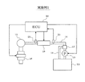
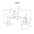
まず、図1に基づいて吸気ポート噴射式エンジンの燃料供給システム全体の概略構成を説明する。
A first embodiment of the present invention will be described with reference to FIGS.
First, a schematic configuration of an entire fuel supply system of an intake port injection engine will be described with reference to FIG.
内燃機関であるエンジン(図示せず)は、燃料として、ガソリン、アルコール(エタノールやメタノール等)、ガソリンにアルコールを混合したアルコール混合燃料をいずれも使用可能であり、これらのガソリン、アルコール、アルコール混合燃料のいずれかを燃料タンク12に給油してエンジンに供給するようになっている。燃料を貯溜する燃料タンク12には、燃料を汲み上げる燃料ポンプ13が設置されている。この燃料ポンプ13は、バッテリ(図示せず)を電源とする電動モータ(図示せず)によって駆動される。この燃料ポンプ13から吐出される燃料は、燃料配管14を通してデリバリパイプ15に送られ、このデリバリパイプ15からエンジンの各気筒の燃料噴射弁16に分配される。
The internal combustion engine (not shown) can use gasoline, alcohol (ethanol, methanol, etc.), and alcohol mixed fuel in which gasoline is mixed with alcohol as fuel. Any one of the fuel is supplied to the
燃料配管14のうちの燃料ポンプ13付近には、プレッシャレギュレータ17が接続され、このプレッシャレギュレータ17によって燃料ポンプ13の吐出圧力が所定圧力に調圧され、その圧力を越える燃料の余剰分が燃料戻し配管18により燃料タンク12内に戻されるようになっている。
A
また、燃料配管14の途中には、燃料を加熱するPTCヒータ(自己温度調節型ヒータ)等のヒータ19(燃料加熱手段)が設けられている。本実施例1では、燃料配管14の外側にヒータ19が配置されて、燃料配管14の外側から燃料配管14内の燃料を間接的に加熱するようになっている。尚、燃料配管14の内部にヒータを配置して、燃料配管14内の燃料をヒータで直接加熱するようにしても良い等、ヒータの位置や種類等を適宜変更しても良い。
A heater 19 (fuel heating means) such as a PTC heater (self-temperature adjusting heater) for heating the fuel is provided in the middle of the
更に、燃料配管14のうちのヒータ19の上流側には、燃料配管14内の燃料圧力を検出する燃圧センサ20(燃料圧力判定手段)が配置され、燃料配管14のうちのヒータ19の出口部付近には、燃料配管14内の燃料温度(つまりヒータ19で加熱された燃料の温度)を検出する燃温センサ21(燃料温度判定手段)が配置されている。
Further, a fuel pressure sensor 20 (fuel pressure determination means) for detecting the fuel pressure in the
これら各種センサの出力は、制御回路(以下「ECU」と表記する)22に入力される。このECU22は、マイクロコンピュータを主体として構成され、内蔵されたROM(記憶媒体)に記憶された各種のエンジン制御プログラムを実行することで、エンジン運転状態に応じて燃料噴射弁16の燃料噴射量や点火プラグ(図示せず)の点火時期を制御する。尚、ECU22は、エンジン(燃料噴射弁16や点火プラグ等)、燃料ポンプ13、ヒータ19等を総合的に制御する1つの制御回路で構成しても良いし、エンジンを制御するエンジン制御回路と、燃料ポンプ13を制御するポンプ制御回路と、ヒータ19を制御するヒータ制御回路等を別々に設けた構成としても良い。
Outputs of these various sensors are input to a control circuit (hereinafter referred to as “ECU”) 22. The
また、ECU22は、ヒータ19で燃料を加熱する際に燃料中にベーパが発生することを防止するために、後述する図2の燃料温度制御ルーチンを実行することで、燃料温度制御を次のようにして行う。まず、燃料加熱領域(ヒータ19で燃料を加熱しないと始動が困難な低温領域)であるか否かを判定し、燃料加熱領域であると判定された場合には、燃料圧力Pと燃料のアルコール濃度とに応じて目標燃料温度Tref (例えば燃料の沸点よりも少し低い温度)を設定し、燃料温度Tが目標燃料温度Tref 以上であるか否かを判定する。その結果、燃料温度Tが目標燃料温度Tref よりも低いと判定された場合には、ヒータ19の通電をオンして、ヒータ19で燃料を加熱する。一方、燃料温度Tが目標燃料温度Tref 以上であると判定された場合には、ヒータ19の通電をオフして、ヒータ19による燃料の加熱を停止する。これにより、燃料温度Tを目標燃料温度Tref 付近に制御するようにヒータ19の通電を制御する。
Further, the
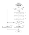
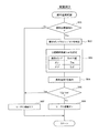
以下、ECU22が実行する図2の燃料温度制御ルーチンの処理内容を説明する。
図2に示す燃料温度制御ルーチンは、ECU22の電源オン中に所定周期で繰り返し実行される。本ルーチンが起動されると、まず、ステップ101で、燃料加熱領域(ヒータ19で燃料を加熱しないと始動が困難な低温領域)であるか否かを、例えば、冷却水温が始動可能水温よりも低いか否か等によって判定する。尚、始動可能水温は、燃料のアルコール濃度に応じて変化させるようにしても良い。ここで、燃料のアルコール濃度は、アルコール濃度センサで検出するようにしても良いが、アルコール濃度センサを備えていないシステムの場合には、燃料のアルコール濃度に応じて変動するパラメータ、例えば、空燃比フィードバック補正量、空燃比のずれ量、燃焼安定性(エンジン回転変動)、エンジントルク、高温始動時の燃圧上昇速度等の少なくとも1つに基づいて燃料のアルコール濃度を推定するようにしても良い。
The processing contents of the fuel temperature control routine of FIG. 2 executed by the
The fuel temperature control routine shown in FIG. 2 is repeatedly executed at a predetermined cycle while the
このステップ101で、燃料加熱領域ではないと判定された場合には、燃料を加熱する必要がないため、ステップ107に進み、ヒータ19の通電をオフしたまま、本ルーチンを終了する。
If it is determined in
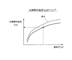
一方、上記ステップ101で、燃料加熱領域であると判定された場合には、ステップ102に進み、燃圧センサ20で検出した燃料圧力Pを読み込んだ後、ステップ103に進み、図3の目標燃料温度Tref のマップを参照して、燃料圧力Pと燃料のアルコール濃度とに応じた目標燃料温度Tref を算出する。
On the other hand, if it is determined in
ここで、目標燃料温度Tref のマップは、燃料のアルコール濃度毎に燃料圧力Pに応じた目標燃料温度Tref が設定されている。尚、図3では燃料のアルコール濃度が所定値の場合の例を示している。図3に破線で示すように、燃料圧力が高くなるほど燃料の沸点(つまりベーパが発生する燃料温度)が高くなると共に、燃料のアルコール濃度が高くなるほど沸点が低くなるという特性があるため、図3に実線で示す目標燃料温度Tref のマップは、目標燃料温度Tref が燃料の沸点よりも少し低い温度になるように、燃料圧力Pが高くなるほど目標燃料温度Tref が高くなると共に、燃料のアルコール濃度が高くなるほど目標燃料温度Tref が低くなるように設定されている。このステップ103の処理が特許請求の範囲でいう目標燃料温度設定手段としての役割を果たす。
Here, in the map of the target fuel temperature Tref, the target fuel temperature Tref corresponding to the fuel pressure P is set for each alcohol concentration of the fuel. FIG. 3 shows an example in which the alcohol concentration of the fuel is a predetermined value. As indicated by the broken line in FIG. 3, the fuel boiling point (ie, the fuel temperature at which vapor is generated) increases as the fuel pressure increases, and the boiling point decreases as the alcohol concentration of the fuel increases. In the map of the target fuel temperature Tref indicated by a solid line, the target fuel temperature Tref increases as the fuel pressure P increases so that the target fuel temperature Tref is slightly lower than the boiling point of the fuel, and the alcohol concentration of the fuel increases. The target fuel temperature Tref is set to be lower as the temperature is higher. The processing in
尚、上記ステップ103では、燃料圧力Pと燃料のアルコール濃度とに応じて目標燃料温度Tref を算出するようにしたが、燃料圧力Pのみに応じて目標燃料温度Tref を算出するようにしても良く、この場合、燃料のアルコール濃度が高くなるほど沸点が低くなるという特性を考慮して、燃料のアルコール濃度が例えば100%のときの沸点よりも目標燃料温度Tref が低くなるように目標燃料温度Tref のマップを設定すれば良い。
In
この後、ステップ104に進み、燃温センサ21で検出した燃料温度Tを読み込んだ後、ステップ105に進み、検出した燃料温度Tが目標燃料温度Tref 以上であるか否かを判定し、燃料温度Tが目標燃料温度Tref よりも低いと判定された場合には、ステップ106に進み、ヒータ19の通電をオンして、ヒータ19で燃料を加熱する。
Thereafter, the process proceeds to step 104, and after reading the fuel temperature T detected by the
一方、上記ステップ105で、燃料温度Tが目標燃料温度Tref 以上であると判定された場合には、ステップ107に進み、ヒータ19の通電をオフして、ヒータ19による燃料の加熱を停止する。これらのステップ105〜107の処理により、燃料温度Tを目標燃料温度Tref 付近に制御するようにヒータ19の通電を制御する処理が実行され、特許請求の範囲でいう燃料温度制御手段としての役割が果たされる。
On the other hand, if it is determined in
以上説明した本実施例1では、燃料圧力Pと燃料のアルコール濃度に応じて目標燃料温度Tref を設定するようにしたので、燃料圧力Pや燃料のアルコール濃度に応じて燃料の沸点(つまりベーパが発生する燃料温度)が変化するのに対応して、目標燃料温度Tref を変化させて、目標燃料温度Tref を適正温度(例えば沸点よりも少し低い温度)に設定することができる。そして、燃料温度Tを目標燃料温度Tref 付近に制御するようにヒータ19の通電を制御するようにしたので、燃料温度Tを沸点よりも低い温度に精度良く制御することができ、ベーパの発生を確実に防止することができる。これにより、ベーパの発生による燃料噴射量の不足や燃料圧力の脈動(燃料噴射量の変動)を防止することができる。
In the first embodiment described above, since the target fuel temperature Tref is set according to the fuel pressure P and the alcohol concentration of the fuel, the boiling point (that is, the vapor of the fuel) depends on the fuel pressure P and the alcohol concentration of the fuel. The target fuel temperature Tref can be changed to set the target fuel temperature Tref to an appropriate temperature (for example, a temperature slightly lower than the boiling point) in response to the change in the generated fuel temperature). Since the energization of the
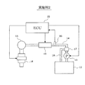
次に、図4及び図5を用いて本発明の実施例2を説明する。但し、前記実施例1と実質的に同一部分については説明を省略又は簡略化し、主として前記実施例1と異なる部分について説明する。 Next, Embodiment 2 of the present invention will be described with reference to FIGS. However, description of substantially the same parts as those in the first embodiment will be omitted or simplified, and different parts from the first embodiment will be mainly described.
本実施例2では、図4に示すように、燃温センサが省略され、その他のシステム構成は、前記実施例1で説明した図1の構成と同じである。
そして、ECU22は、後述する図5の燃料温度制御ルーチンを実行することで、燃料温度制御を行う際に、ヒータ19の作動状態と燃料噴射弁16の燃料噴射量Q等に基づいて燃料温度Tを推定するようにしている。
In the second embodiment, as shown in FIG. 4, the fuel temperature sensor is omitted, and the other system configuration is the same as the configuration of FIG. 1 described in the first embodiment.
Then, the
ヒータ19の作動状態(例えば供給電力W)に応じてヒータ19から燃料に与えられる単位時間当りの熱量が変化し、燃料噴射弁16の燃料噴射量Qに応じてヒータ19を通過する単位時間当りの燃料量が変化するため、ヒータ19の作動状態と燃料噴射弁16の燃料噴射量Q等から燃料温度Tを推定することができる。
The amount of heat per unit time given from the
以下、図5の燃料温度制御ルーチンの処理内容を説明する。本ルーチンでは、ステップ201で、燃料加熱領域であると判定された場合に、ステップ202に進み、燃圧センサ20で検出した燃料圧力Pを読み込んだ後、ステップ203に進み、図3の目標燃料温度Tref のマップを参照して、燃料圧力Pと燃料のアルコール濃度とに応じた目標燃料温度Tref を算出する。尚、燃料圧力Pのみに応じて目標燃料温度Tref を算出するようにしても良いことは前述した通りである。
Hereinafter, the processing content of the fuel temperature control routine of FIG. 5 will be described. In this routine, when it is determined in
この後、ステップ204に進み、単位時間(燃料温度の演算周期に相当する時間Δt)当りの燃料噴射弁16の燃料噴射量Qを算出した後、ステップ205に進み、ヒータ19の出口部付近の燃料配管14内の燃料温度Tを次式により算出することで、燃料温度Tを推定する。
Thereafter, the process proceeds to step 204, and after calculating the fuel injection amount Q of the

ここで、T(i) は今回の燃料温度の算出値、T(i-1) は前回の燃料温度の算出値である。また、ρは燃料の密度、cは燃料の比熱である。また、Tcoolは加熱前の燃料温度(冷却水温で代用しても良い)、Wはヒータ19の供給電力(通電オフ時は0)である。更に、Δtは燃料温度の演算周期に相当する時間、Qtotal はヒータ19の入口部から出口部までの燃料配管14内の燃料量である。このステップ205の処理が特許請求の範囲でいう燃料温度判定手段としての役割を果たす。
Here, T (i) is the calculated value of the current fuel temperature, and T (i-1) is the calculated value of the previous fuel temperature. Ρ is the density of the fuel, and c is the specific heat of the fuel. Further, Tcool is the fuel temperature before heating (the cooling water temperature may be substituted), and W is the power supplied to the heater 19 (0 when energized is off). Further, Δt is a time corresponding to the calculation cycle of the fuel temperature, and Qtotal is the amount of fuel in the
この後、ステップ206に進み、推定した燃料温度Tが目標燃料温度Tref 以上であるか否かを判定し、燃料温度Tが目標燃料温度Tref よりも低いと判定された場合には、ステップ207に進み、ヒータ19の通電をオンして、ヒータ19で燃料を加熱する。一方、上記ステップ206で、燃料温度Tが目標燃料温度Tref 以上であると判定された場合には、ステップ208に進み、ヒータ19の通電をオフして、ヒータ19による燃料の加熱を停止する。
Thereafter, the process proceeds to step 206, where it is determined whether or not the estimated fuel temperature T is equal to or higher than the target fuel temperature Tref. If it is determined that the fuel temperature T is lower than the target fuel temperature Tref, the process proceeds to step 207. The
以上説明した本実施例2では、燃料温度制御を行う際に、ヒータ19の出力電力Wと燃料噴射弁16の燃料噴射量Q等に基づいて燃料温度Tを推定するようにしたので、燃温センサを省略した構成にすることができ、近年の重要な技術的課題である低コスト化の要求を満たすことができる。尚、燃料温度Tの推定方法は、適宜変更しても良い。
In the second embodiment described above, when the fuel temperature control is performed, the fuel temperature T is estimated based on the output power W of the
次に、図6及び図7を用いて本発明の実施例3を説明する。但し、前記実施例1と実質的に同一部分については説明を省略又は簡略化し、主として前記実施例1と異なる部分について説明する。 Next, Embodiment 3 of the present invention will be described with reference to FIGS. However, description of substantially the same parts as those in the first embodiment will be omitted or simplified, and different parts from the first embodiment will be mainly described.
本実施例3では、図6に示すように、燃圧センサが省略され、その他のシステム構成は、前記実施例1で説明した図1の構成と同じである。
そして、ECU22は、後述する図7の燃料温度制御ルーチンを実行することで、燃料温度制御を行う際に、燃料ポンプ13の作動状態に基づいて燃料圧力Pを推定するようにしている。
In the third embodiment, as shown in FIG. 6, the fuel pressure sensor is omitted, and the other system configuration is the same as the configuration of FIG. 1 described in the first embodiment.
The
燃料ポンプ13がオン(作動中)のときにはプレッシャレギュレータ17により燃料ポンプ13の吐出圧力が所定圧力Pmax に調圧されて燃料圧力Pが所定圧力Pmax に維持され、燃料ポンプ13がオフ(停止中)のときには燃料圧力Pが所定圧力Pmax よりも低い圧力に低下するため、燃料ポンプ13の作動状態(例えばオン/オフ)から燃料圧力Pを推定することができる。
When the
以下、図7の燃料温度制御ルーチンの処理内容を説明する。本ルーチンでは、ステップ301で、燃料加熱領域であると判定された場合に、ステップ302に進み、燃料ポンプ13がオンかオフかを判定する。
Hereinafter, the processing content of the fuel temperature control routine of FIG. 7 will be described. In this routine, when it is determined in
この後、ステップ303に進み、燃料ポンプ13がオンの場合には、燃料圧力Pが所定圧力Pmax であると推定して、燃料圧力Pが所定圧力Pmax のときの沸点よりも少し低い温度Tonを目標燃料温度Tref として設定する。一方、燃料ポンプ13がオフの場合には、燃料圧力Pが所定圧力Pmax よりも低い圧力に低下していると推定して、燃料圧力Pが所定圧力Pmax よりも低い圧力(例えば大気圧)のときの沸点よりも少し低い温度Toff を目標燃料温度Tref として設定する。この場合、燃料ポンプ13のオン/オフに基づいて燃料圧力Pを推定する機能が特許請求の範囲でいう燃料圧力判定手段としての役割を果たす。
Thereafter, the process proceeds to step 303, and when the
この後、ステップ304に進み、燃温センサ21で検出した燃料温度Tを読み込んだ後、ステップ305に進み、検出した燃料温度Tが目標燃料温度Tref 以上であるか否かを判定し、燃料温度Tが目標燃料温度Tref よりも低いと判定された場合には、ステップ306に進み、ヒータ19の通電をオンして、ヒータ19で燃料を加熱する。
Thereafter, the process proceeds to step 304, and after reading the fuel temperature T detected by the
一方、上記ステップ305で、燃料温度Tが目標燃料温度Tref 以上であると判定された場合には、ステップ307に進み、ヒータ19の通電をオフして、ヒータ19による燃料の加熱を停止する。
On the other hand, if it is determined in
尚、燃料ポンプ13がオフの場合の目標燃料温度Tref を十分に低い温度に設定することで、燃料ポンプ13がオフの場合には、必ずヒータ19の通電をオフして、ヒータ19による燃料の加熱を停止するようにしても良い。
By setting the target fuel temperature Tref when the
以上説明した本実施例3では、燃料温度制御を行う際に、燃料ポンプ13のオン/オフ)に基づいて燃料圧力Pを推定するようにしたので、燃圧センサを省略した構成にすることができ、近年の重要な技術的課題である低コスト化の要求を満たすことができる。
In the third embodiment described above, the fuel pressure P is estimated on the basis of the on / off state of the
尚、燃料圧力Pの推定方法は、適宜変更しても良く、例えば、燃料ポンプ13の負荷(例えば、燃料ポンプ13の駆動電流や駆動電圧)等に基づいて燃料圧力Pを推定するようにしても良い。
また、上記実施例3では、燃温センサ21で燃料温度Tを検出するようにしたが、燃料温度Tを推定するようにしても良い。
The method for estimating the fuel pressure P may be changed as appropriate. For example, the fuel pressure P is estimated based on the load of the fuel pump 13 (for example, the drive current or drive voltage of the fuel pump 13). Also good.
In the third embodiment, the fuel temperature T is detected by the
その他、本発明は、吸気ポート噴射式エンジンに限定されず、筒内噴射式エンジンや、吸気ポート噴射用の燃料噴射弁と筒内噴射用の燃料噴射弁の両方を備えたデュアル噴射式のエンジンにも適用して実施できる。 In addition, the present invention is not limited to the intake port injection type engine, but is an in-cylinder injection type engine or a dual injection type engine having both a fuel injection valve for intake port injection and a fuel injection valve for in-cylinder injection It can also be applied to.
12…燃料タンク、13…燃料ポンプ、14…燃料配管、16…燃料噴射弁、17…プレッシャレギュレータ、19…ヒータ(燃料加熱手段)、20…燃圧センサ(燃料圧力判定手段)、21…燃温センサ(燃料温度判定手段)、22…ECU(目標燃料温度設定手段,燃料温度制御手段,燃料圧力判定手段,燃料温度判定手段)
DESCRIPTION OF
Claims (6)
前記燃料の温度を検出又は推定する燃料温度判定手段と、
前記燃料の圧力を検出又は推定する燃料圧力判定手段と、
前記燃料圧力判定手段で検出又は推定した燃料圧力に応じて目標燃料温度を設定する目標燃料温度設定手段と、
前記燃料温度判定手段で検出又は推定した燃料温度を前記目標燃料温度にするように前記燃料加熱手段を制御する燃料温度制御手段と
を備えていることを特徴とする内燃機関の燃料温度制御装置。 In a fuel temperature control device for an internal combustion engine comprising a fuel heating means for heating fuel supplied to the internal combustion engine,
Fuel temperature determination means for detecting or estimating the temperature of the fuel;
Fuel pressure determination means for detecting or estimating the pressure of the fuel;
Target fuel temperature setting means for setting a target fuel temperature according to the fuel pressure detected or estimated by the fuel pressure determination means;
A fuel temperature control device for an internal combustion engine, comprising: fuel temperature control means for controlling the fuel heating means so that the fuel temperature detected or estimated by the fuel temperature determination means becomes the target fuel temperature.
前記燃料ポンプの吐出圧力を所定圧力に調圧するプレッシャレギュレータとを備え、
前記燃料圧力判定手段は、前記燃料ポンプの作動状態に基づいて前記燃料の圧力を推定することを特徴とする請求項1乃至3のいずれかに記載の内燃機関の燃料温度制御装置。 A fuel pump for supplying the fuel in the fuel tank to the internal combustion engine;
A pressure regulator that regulates the discharge pressure of the fuel pump to a predetermined pressure;
4. The fuel temperature control apparatus for an internal combustion engine according to claim 1, wherein the fuel pressure determination means estimates the pressure of the fuel based on an operating state of the fuel pump.
前記目標燃料温度設定手段は、前記アルコール濃度判定手段で検出又は推定した燃料のアルコール濃度も考慮して前記目標燃料温度を設定することを特徴とする請求項1乃至5のいずれかに記載の内燃機関の燃料温度制御装置。 Comprising alcohol concentration determination means for detecting or estimating the alcohol concentration of the fuel;
6. The internal combustion engine according to claim 1, wherein the target fuel temperature setting means sets the target fuel temperature in consideration of the alcohol concentration of the fuel detected or estimated by the alcohol concentration determination means. Engine fuel temperature control device.
Priority Applications (2)
| Application Number | Priority Date | Filing Date | Title |
|---|---|---|---|
| JP2008201369A JP2010038024A (en) | 2008-08-05 | 2008-08-05 | Fuel temperature control device of internal combustion engine |
| BRPI0902488-3A BRPI0902488B1 (en) | 2008-08-05 | 2009-07-30 | fuel temperature controller for an internal combustion engine |
Applications Claiming Priority (1)
| Application Number | Priority Date | Filing Date | Title |
|---|---|---|---|
| JP2008201369A JP2010038024A (en) | 2008-08-05 | 2008-08-05 | Fuel temperature control device of internal combustion engine |
Publications (1)
| Publication Number | Publication Date |
|---|---|
| JP2010038024A true JP2010038024A (en) | 2010-02-18 |
Family
ID=42010829
Family Applications (1)
| Application Number | Title | Priority Date | Filing Date |
|---|---|---|---|
| JP2008201369A Withdrawn JP2010038024A (en) | 2008-08-05 | 2008-08-05 | Fuel temperature control device of internal combustion engine |
Country Status (2)
| Country | Link |
|---|---|
| JP (1) | JP2010038024A (en) |
| BR (1) | BRPI0902488B1 (en) |
Cited By (5)
| Publication number | Priority date | Publication date | Assignee | Title |
|---|---|---|---|---|
| WO2011101980A1 (en) * | 2010-02-19 | 2011-08-25 | トヨタ自動車株式会社 | Abnormality detection device for fuel property detection device |
| KR20140078424A (en) * | 2012-12-17 | 2014-06-25 | 현대자동차주식회사 | Cold start system for ethanol vehicle and method thereof |
| US9163593B2 (en) | 2012-12-28 | 2015-10-20 | Hyundai Motor Company | Fuel heating device for improving cold start performance of flex fuel vehicle |
| JP2018048614A (en) * | 2016-09-23 | 2018-03-29 | 株式会社デンソー | Heater driving device |
| US11746722B2 (en) * | 2018-12-26 | 2023-09-05 | Robert Bosch Limitada | Method of control of fuel temperature injected in combustion engine |
Families Citing this family (7)
| Publication number | Priority date | Publication date | Assignee | Title |
|---|---|---|---|---|
| BR102018077092A2 (en) | 2018-12-26 | 2020-07-07 | Robert Bosch Limitada | method of preheating and temperature control of fuel injected into a combustion engine |
| BR102019006777B1 (en) * | 2019-04-03 | 2021-06-22 | Vitorio Francisco Rizzotto | device for saving fuel via heating and controlled temperature maintenance |
| BR102019027843A2 (en) | 2019-12-26 | 2021-07-06 | Robert Bosch Limitada | system and method of managing the temperature of fuel injected in internal combustion engines |
| BR102019027845A2 (en) | 2019-12-26 | 2021-07-06 | Robert Bosch Limitada | system and method of managing the temperature of fuel injected in internal combustion engines |
| BR102020020172A2 (en) * | 2020-10-01 | 2022-04-12 | Robert Bosch Limitada | Injected fuel temperature management method in internal combustion engines |
| BR102020024436A2 (en) * | 2020-11-30 | 2022-06-07 | Robert Bosch Limitada | System and method of managing the temperature of fuel injected into internal combustion engines from a mixture of an air and fuel flow applicable to a vehicle |
| BR102020024417A2 (en) * | 2020-11-30 | 2022-06-07 | Robert Bosch Limitada | System and method of managing the temperature of fuel injected into internal combustion engines from a mixture of an air and fuel flow applicable to a vehicle |
-
2008
- 2008-08-05 JP JP2008201369A patent/JP2010038024A/en not_active Withdrawn
-
2009
- 2009-07-30 BR BRPI0902488-3A patent/BRPI0902488B1/en active IP Right Grant
Cited By (10)
| Publication number | Priority date | Publication date | Assignee | Title |
|---|---|---|---|---|
| WO2011101980A1 (en) * | 2010-02-19 | 2011-08-25 | トヨタ自動車株式会社 | Abnormality detection device for fuel property detection device |
| CN102770643A (en) * | 2010-02-19 | 2012-11-07 | 丰田自动车株式会社 | Abnormality detection device for fuel property detection device |
| EP2538059A1 (en) * | 2010-02-19 | 2012-12-26 | Toyota Jidosha Kabushiki Kaisha | Abnormality detection device for fuel property detection device |
| JP5240397B2 (en) * | 2010-02-19 | 2013-07-17 | トヨタ自動車株式会社 | Abnormality detection device for fuel property detection device |
| EP2538059A4 (en) * | 2010-02-19 | 2014-02-26 | Toyota Motor Co Ltd | Abnormality detection device for fuel property detection device |
| US8683853B2 (en) | 2010-02-19 | 2014-04-01 | Toyota Jidosha Kabushiki Kaisha | Apparatus for detecting abnormality for fuel property detecting apparatus |
| KR20140078424A (en) * | 2012-12-17 | 2014-06-25 | 현대자동차주식회사 | Cold start system for ethanol vehicle and method thereof |
| US9163593B2 (en) | 2012-12-28 | 2015-10-20 | Hyundai Motor Company | Fuel heating device for improving cold start performance of flex fuel vehicle |
| JP2018048614A (en) * | 2016-09-23 | 2018-03-29 | 株式会社デンソー | Heater driving device |
| US11746722B2 (en) * | 2018-12-26 | 2023-09-05 | Robert Bosch Limitada | Method of control of fuel temperature injected in combustion engine |
Also Published As
| Publication number | Publication date |
|---|---|
| BRPI0902488B1 (en) | 2021-02-02 |
| BRPI0902488A2 (en) | 2010-04-20 |
Similar Documents
| Publication | Publication Date | Title |
|---|---|---|
| JP2010038024A (en) | Fuel temperature control device of internal combustion engine | |
| JP4534866B2 (en) | Engine control device | |
| US9194353B2 (en) | Fuel injection control system for internal combustion engine | |
| US20160123276A1 (en) | Liquefied gas fuel supplying apparatus | |
| US8566004B2 (en) | Fuel injection control apparatus for internal combustion engine | |
| JP2010037968A (en) | Fuel injection control device for internal combustion engine | |
| JP2009185676A (en) | Fuel supply device for internal combustion engine | |
| JP2009180130A (en) | Engine start control device | |
| JP2010265774A (en) | Starter and starting method for internal combustion engine | |
| JP2005351189A (en) | Device for supplying gaseous lpg to engine | |
| JP4322297B2 (en) | Control device for internal combustion engine | |
| CN108223158B (en) | Apparatus and method for controlling oxygen sensor | |
| JP2005337023A (en) | Fuel delivery device for engine | |
| JP4052521B2 (en) | Control device for internal combustion engine | |
| JP5079744B2 (en) | Fuel vapor pressure measurement system | |
| JP2011220208A (en) | Control device of internal combustion engine | |
| JP5315139B2 (en) | Fuel supply device for internal combustion engine for alcohol mixed fuel | |
| JP2007056679A (en) | Liquified petroleum gas fuel feeder of engine | |
| JP2006046210A (en) | Vaporized gas fuel supply device for engine | |
| JP2006194110A (en) | Control method of fuel feeder of internal combustion engine | |
| JP2009062874A (en) | Control device of internal combustion engine | |
| JP5698441B2 (en) | Gas fuel supply device | |
| JP2010024853A (en) | Control device for internal combustion engine | |
| JP2009030494A (en) | Control device for diesel engine | |
| JP5956293B2 (en) | engine |
Legal Events
| Date | Code | Title | Description |
|---|---|---|---|
| A300 | Withdrawal of application because of no request for examination |
Free format text: JAPANESE INTERMEDIATE CODE: A300 Effective date: 20111101 |