EP2878703A1 - Metal oxide-polymer laminate and production method thereof - Google Patents
Metal oxide-polymer laminate and production method thereof Download PDFInfo
- Publication number
- EP2878703A1 EP2878703A1 EP14194470.2A EP14194470A EP2878703A1 EP 2878703 A1 EP2878703 A1 EP 2878703A1 EP 14194470 A EP14194470 A EP 14194470A EP 2878703 A1 EP2878703 A1 EP 2878703A1
- Authority
- EP
- European Patent Office
- Prior art keywords
- metal oxide
- layer
- polymer layer
- polymer
- oxide layer
- Prior art date
- Legal status (The legal status is an assumption and is not a legal conclusion. Google has not performed a legal analysis and makes no representation as to the accuracy of the status listed.)
- Withdrawn
Links
Images
Classifications
-
- C—CHEMISTRY; METALLURGY
- C23—COATING METALLIC MATERIAL; COATING MATERIAL WITH METALLIC MATERIAL; CHEMICAL SURFACE TREATMENT; DIFFUSION TREATMENT OF METALLIC MATERIAL; COATING BY VACUUM EVAPORATION, BY SPUTTERING, BY ION IMPLANTATION OR BY CHEMICAL VAPOUR DEPOSITION, IN GENERAL; INHIBITING CORROSION OF METALLIC MATERIAL OR INCRUSTATION IN GENERAL
- C23C—COATING METALLIC MATERIAL; COATING MATERIAL WITH METALLIC MATERIAL; SURFACE TREATMENT OF METALLIC MATERIAL BY DIFFUSION INTO THE SURFACE, BY CHEMICAL CONVERSION OR SUBSTITUTION; COATING BY VACUUM EVAPORATION, BY SPUTTERING, BY ION IMPLANTATION OR BY CHEMICAL VAPOUR DEPOSITION, IN GENERAL
- C23C14/00—Coating by vacuum evaporation, by sputtering or by ion implantation of the coating forming material
- C23C14/22—Coating by vacuum evaporation, by sputtering or by ion implantation of the coating forming material characterised by the process of coating
-
- B—PERFORMING OPERATIONS; TRANSPORTING
- B05—SPRAYING OR ATOMISING IN GENERAL; APPLYING FLUENT MATERIALS TO SURFACES, IN GENERAL
- B05D—PROCESSES FOR APPLYING FLUENT MATERIALS TO SURFACES, IN GENERAL
- B05D1/00—Processes for applying liquids or other fluent materials
- B05D1/02—Processes for applying liquids or other fluent materials performed by spraying
- B05D1/08—Flame spraying
- B05D1/10—Applying particulate materials
-
- B—PERFORMING OPERATIONS; TRANSPORTING
- B05—SPRAYING OR ATOMISING IN GENERAL; APPLYING FLUENT MATERIALS TO SURFACES, IN GENERAL
- B05D—PROCESSES FOR APPLYING FLUENT MATERIALS TO SURFACES, IN GENERAL
- B05D1/00—Processes for applying liquids or other fluent materials
- B05D1/02—Processes for applying liquids or other fluent materials performed by spraying
- B05D1/12—Applying particulate materials
-
- C—CHEMISTRY; METALLURGY
- C23—COATING METALLIC MATERIAL; COATING MATERIAL WITH METALLIC MATERIAL; CHEMICAL SURFACE TREATMENT; DIFFUSION TREATMENT OF METALLIC MATERIAL; COATING BY VACUUM EVAPORATION, BY SPUTTERING, BY ION IMPLANTATION OR BY CHEMICAL VAPOUR DEPOSITION, IN GENERAL; INHIBITING CORROSION OF METALLIC MATERIAL OR INCRUSTATION IN GENERAL
- C23C—COATING METALLIC MATERIAL; COATING MATERIAL WITH METALLIC MATERIAL; SURFACE TREATMENT OF METALLIC MATERIAL BY DIFFUSION INTO THE SURFACE, BY CHEMICAL CONVERSION OR SUBSTITUTION; COATING BY VACUUM EVAPORATION, BY SPUTTERING, BY ION IMPLANTATION OR BY CHEMICAL VAPOUR DEPOSITION, IN GENERAL
- C23C14/00—Coating by vacuum evaporation, by sputtering or by ion implantation of the coating forming material
- C23C14/06—Coating by vacuum evaporation, by sputtering or by ion implantation of the coating forming material characterised by the coating material
- C23C14/08—Oxides
- C23C14/083—Oxides of refractory metals or yttrium
-
- C—CHEMISTRY; METALLURGY
- C23—COATING METALLIC MATERIAL; COATING MATERIAL WITH METALLIC MATERIAL; CHEMICAL SURFACE TREATMENT; DIFFUSION TREATMENT OF METALLIC MATERIAL; COATING BY VACUUM EVAPORATION, BY SPUTTERING, BY ION IMPLANTATION OR BY CHEMICAL VAPOUR DEPOSITION, IN GENERAL; INHIBITING CORROSION OF METALLIC MATERIAL OR INCRUSTATION IN GENERAL
- C23C—COATING METALLIC MATERIAL; COATING MATERIAL WITH METALLIC MATERIAL; SURFACE TREATMENT OF METALLIC MATERIAL BY DIFFUSION INTO THE SURFACE, BY CHEMICAL CONVERSION OR SUBSTITUTION; COATING BY VACUUM EVAPORATION, BY SPUTTERING, BY ION IMPLANTATION OR BY CHEMICAL VAPOUR DEPOSITION, IN GENERAL
- C23C14/00—Coating by vacuum evaporation, by sputtering or by ion implantation of the coating forming material
- C23C14/58—After-treatment
-
- C—CHEMISTRY; METALLURGY
- C23—COATING METALLIC MATERIAL; COATING MATERIAL WITH METALLIC MATERIAL; CHEMICAL SURFACE TREATMENT; DIFFUSION TREATMENT OF METALLIC MATERIAL; COATING BY VACUUM EVAPORATION, BY SPUTTERING, BY ION IMPLANTATION OR BY CHEMICAL VAPOUR DEPOSITION, IN GENERAL; INHIBITING CORROSION OF METALLIC MATERIAL OR INCRUSTATION IN GENERAL
- C23C—COATING METALLIC MATERIAL; COATING MATERIAL WITH METALLIC MATERIAL; SURFACE TREATMENT OF METALLIC MATERIAL BY DIFFUSION INTO THE SURFACE, BY CHEMICAL CONVERSION OR SUBSTITUTION; COATING BY VACUUM EVAPORATION, BY SPUTTERING, BY ION IMPLANTATION OR BY CHEMICAL VAPOUR DEPOSITION, IN GENERAL
- C23C24/00—Coating starting from inorganic powder
- C23C24/02—Coating starting from inorganic powder by application of pressure only
- C23C24/04—Impact or kinetic deposition of particles
-
- B—PERFORMING OPERATIONS; TRANSPORTING
- B05—SPRAYING OR ATOMISING IN GENERAL; APPLYING FLUENT MATERIALS TO SURFACES, IN GENERAL
- B05D—PROCESSES FOR APPLYING FLUENT MATERIALS TO SURFACES, IN GENERAL
- B05D2201/00—Polymeric substrate or laminate
- B05D2201/02—Polymeric substrate
-
- B—PERFORMING OPERATIONS; TRANSPORTING
- B05—SPRAYING OR ATOMISING IN GENERAL; APPLYING FLUENT MATERIALS TO SURFACES, IN GENERAL
- B05D—PROCESSES FOR APPLYING FLUENT MATERIALS TO SURFACES, IN GENERAL
- B05D2201/00—Polymeric substrate or laminate
- B05D2201/04—Laminate
-
- B—PERFORMING OPERATIONS; TRANSPORTING
- B05—SPRAYING OR ATOMISING IN GENERAL; APPLYING FLUENT MATERIALS TO SURFACES, IN GENERAL
- B05D—PROCESSES FOR APPLYING FLUENT MATERIALS TO SURFACES, IN GENERAL
- B05D2201/00—Polymeric substrate or laminate
- B05D2201/04—Laminate
- B05D2201/06—Laminate of which the last layer is not a polymer
-
- Y—GENERAL TAGGING OF NEW TECHNOLOGICAL DEVELOPMENTS; GENERAL TAGGING OF CROSS-SECTIONAL TECHNOLOGIES SPANNING OVER SEVERAL SECTIONS OF THE IPC; TECHNICAL SUBJECTS COVERED BY FORMER USPC CROSS-REFERENCE ART COLLECTIONS [XRACs] AND DIGESTS
- Y10—TECHNICAL SUBJECTS COVERED BY FORMER USPC
- Y10T—TECHNICAL SUBJECTS COVERED BY FORMER US CLASSIFICATION
- Y10T428/00—Stock material or miscellaneous articles
- Y10T428/249921—Web or sheet containing structurally defined element or component
- Y10T428/249953—Composite having voids in a component [e.g., porous, cellular, etc.]
- Y10T428/249986—Void-containing component contains also a solid fiber or solid particle
-
- Y—GENERAL TAGGING OF NEW TECHNOLOGICAL DEVELOPMENTS; GENERAL TAGGING OF CROSS-SECTIONAL TECHNOLOGIES SPANNING OVER SEVERAL SECTIONS OF THE IPC; TECHNICAL SUBJECTS COVERED BY FORMER USPC CROSS-REFERENCE ART COLLECTIONS [XRACs] AND DIGESTS
- Y10—TECHNICAL SUBJECTS COVERED BY FORMER USPC
- Y10T—TECHNICAL SUBJECTS COVERED BY FORMER US CLASSIFICATION
- Y10T428/00—Stock material or miscellaneous articles
- Y10T428/249921—Web or sheet containing structurally defined element or component
- Y10T428/249953—Composite having voids in a component [e.g., porous, cellular, etc.]
- Y10T428/249987—With nonvoid component of specified composition
- Y10T428/24999—Inorganic
-
- Y—GENERAL TAGGING OF NEW TECHNOLOGICAL DEVELOPMENTS; GENERAL TAGGING OF CROSS-SECTIONAL TECHNOLOGIES SPANNING OVER SEVERAL SECTIONS OF THE IPC; TECHNICAL SUBJECTS COVERED BY FORMER USPC CROSS-REFERENCE ART COLLECTIONS [XRACs] AND DIGESTS
- Y10—TECHNICAL SUBJECTS COVERED BY FORMER USPC
- Y10T—TECHNICAL SUBJECTS COVERED BY FORMER US CLASSIFICATION
- Y10T428/00—Stock material or miscellaneous articles
- Y10T428/25—Web or sheet containing structurally defined element or component and including a second component containing structurally defined particles
- Y10T428/256—Heavy metal or aluminum or compound thereof
Definitions
- the present invention relates to a metal oxide-polymer laminate and a production method thereof.
- Metal oxide-polymer laminates including a polymer layer and a metal oxide layer laminated thereon have been widely used for application in substrates for electronic components, flexible electronic devices, electrooptic devices, sensor components, medical devices, and as membranes in gas-liquid separation modules (for example, see Japanese Unexamined Patent Publication No. 2012-216684 , Japanese Unexamined Patent Publication No. 2006-128229 , and United States Patent No. 7547393 ).
- the metal oxide-polymer laminates can be produced, for example, by heat pressing a metal oxide layer onto a polymer layer, or by injection of ceramic particles in the thickness direction of a polymer layer.
- An object of the present invention is to provide a metal oxide-polymer laminate having improved adhesive strength at the interface between the metal oxide layer and the polymer layer, and a production method thereof.
- a metal oxide-polymer laminate of the present invention includes a polymer layer, and a metal oxide layer laminated on a surface of the polymer layer and formed by an aerosol deposition method, wherein at least a portion of the metal oxide layer is embedded in the polymer layer in a thickness direction thereof.
- the metal oxide layer is formed by the aerosol deposition method using an aggregate of metal oxide particles.
- the aggregate of metal oxide particles has a median diameter of 0.5 ⁇ m or more and 10 ⁇ m or less.
- the polymer layer is a porous layer.
- a method for producing a metal oxide-polymer laminate includes the steps of: preparing a polymer layer, and forming a metal oxide layer on a surface of the polymer layer by an aerosol deposition method so that at least a portion of the metal oxide layer is embedded in the polymer layer in a thickness direction thereof.
- metal oxide-polymer laminate of the present invention adhesive strength at the interface between the metal oxide layer and the polymer layer is excellent.
- a metal oxide-polymer laminate having excellent adhesive strength at the interface between the metal oxide layer and the polymer layer can be produced.
- a metal oxide-polymer laminate 1 in one embodiment of the present invention includes a polymer layer 2, and a metal oxide layer 3 laminated on one side of the polymer layer 2.
- the polymer layer 2 is formed generally into a flat plate.
- the metal oxide layer 3 extends into the polymer layer 2 with an embedded portion 4.
- the embedded portion 4 is formed by metal oxide material being buried at various depths from the surface of the polymer layer 2 within the thickness direction.
- the exposed part (non-embedded) of oxide layer 3 is formed on top of the embedded area in a continuation of the deposition (coating) process.
- thermoplastic resin examples include thermoplastic resin and thermosetting resin.
- thermoplastic resin is used.
- thermoplastic resin examples include olefin resins such as polyethylene and polypropylene; polyester resins such as polyethylene terephthalate (PET); fluorine resins such as polytetrafluoroethylene (tetrafluoroethylene resin, PTFE), a copolymer of tetrafluoroethylene and ethylene (ETFE), and a tetrafluoroethylene-perfluoroalkylvinylether copolymer (PFE); polyamide resins such as nylon; polyimide resins; polyvinyl chloride (PVC); silicone resin; and cellulose.
- fluorine resins, and olefin resins are used. Of the fluorine resins, more preferably, polytetrafluoroethylene is used.
- thermosetting resin examples include epoxy resin, phenol resin, amino resin, and unsaturated polyester resin.
- the polymer layer 2 may contain other organic compounds, for example, protein.
- the polymer layer 2 may be formed from a single layer, or may be formed from multiple layers.
- the polymer layer 2 is preferably a porous layer.
- Example of the porous layer include a porous membrane nonwoven fabric.
- the metal oxide layer 3 can be embedded reliably by an AD method to be described later.
- the production method is not particularly limited, and for example, can be produced by a dry method, wet method, spunbonding, thermal bonding, chemical bonding, stitch bonding, needle punching, melt blowing, spunlacing, steam jet method, and heat lamination method.
- the polymer layer 2 has thickness X 1 of, for example, 1 ⁇ m or more, preferably 10 ⁇ m or more, more preferably 15 ⁇ m or more, and for example, 1000 ⁇ m or less, preferably 500 ⁇ m or less, more preferably 250 ⁇ m or less.
- the embedded portion 4 has depth (that is, the length in up-down direction where the metal oxide layer 3 to be described later is embedded in the thickness direction) X 2 of, for example, 0.02 ⁇ m or more and 50 ⁇ m or less.
- the embedded portion 4 depth, X 2 should be preferably 0.1 ⁇ m or more, more preferably 0.5 ⁇ m or more, and preferably 5 ⁇ m or less, more preferably 3 ⁇ m or less.
- depth X 2 is 3 ⁇ m or more, more preferably 12 ⁇ m or more, and preferably, 30 ⁇ m or less, more preferably 20 ⁇ m or less.
- the metal oxide layer 3 is generally formed into a flat plate, and is laminated on one side in the thickness direction of the polymer layer 2.
- the metal oxide layer 3 is formed so as a portion is embedded/included in the polymer layer 2 when projected in the thickness direction.
- the metal oxide layer 3 is formed from metal oxide particles (metal oxide powder) by an aerosol deposition method (AD method).
- metals that form the metal oxide particles include zirconia (zirconium oxide), ceria (cerium oxide), alumina, yttria, tungsten oxide, and titanium oxide.
- zirconia and ceria are used, and more preferably, zirconia is used.
- zirconia powders for these metal oxide powders, known or commercially available ones can be used.
- zirconia powder for example, "RC-100” (manufactured by DAIICHI KIGENSO KAGAKU KOGYO CO., LTD.) and “TZ-3Y-E” (manufactured by Tosoh Corporation) are used.
- alumina powder examples include “AL-160SG-3”, “AS-160SG-4", and “AL-45-A” (all trade names, manufactured by Showa Denko K.K.).
- yttria powder include "DTS-Y35" (manufactured by Fujimi Incorporated.).
- metal oxide powders may be used singly or in a combination of two or more.
- the metal oxide particles used in the coating process may be primary (single) particles, or may be formed from aggregates (secondary particles) of primary particles.
- the metal oxide particles are formed from aggregates. This allows for excellent handleability, and reliable embedment of the metal oxide layer 3 in the polymer layer 2 by the AD method.
- the primary particles of the metal oxide particles have an average particle size of, for example, 30 nm or more, preferably 50 nm or more, and for example, 500 nm or less, preferably 300 nm or less.
- the average particle size of the primary particles of the metal oxide particles is measured by, for example, a scanning electron microscope (manufactured by Hitachi High-Technologies Corporation).
- the aggregates (secondary particles) of metal oxide particles have an average particle size (median diameter) of, for example, 0.5 ⁇ m or more, preferably 2 ⁇ m or more, and for example, 10 ⁇ m or less, preferably 5 ⁇ m or less.
- average particle size typically 0.5 ⁇ m or more, preferably 2 ⁇ m or more, and for example, 10 ⁇ m or less, preferably 5 ⁇ m or less.
- the metal oxide particles sprayed by the AD method toward the polymer layer 2 may fail to form the metal oxide layer 3, and may destroy the polymer layer 2 due to excessively large kinetic energy of the impacting particle.
- the average particle size (median diameter) of the metal oxide particles is measured with, for example, a scanning electron microscope (manufactured by Hitachi High-Technologies Corporation).
- the metal oxide layer 3 may contain a known additive other than the metal oxide particles.
- the additive include polymer powder.
- 1.0 mass% or less, preferably 0.5 mass% or less, even more preferably 0 mass% of the additive may be contained relative to the total amount of metal oxide particles and additive mixture. It is recommended that the metal oxide layer 3 is preferably formed only from metal oxide material.
- a polymer layer 2a is formed using known fabrication methods. At this point, no embedded portion 4 is present in the polymer layer 2a.
- an embedded portion 4 and the metal oxide layer 3 are formed in a single deposition step using deposition method (AD method) (formation step).
- AD method deposition method
- an aerosol deposition device 10 as shown in FIG. 2 is used.
- the aerosol deposition device 10 includes a film-forming chamber 11, an aerosol generation chamber 12, and a carrier gas transportation device 13.
- the film-forming chamber 11 is the chamber where the formation of the metal oxide layer 3 on the surface of the polymer layer 2a takes place, and includes a substrate holder 14, a thermometer (not shown) for measuring the temperature in the film-forming chamber 11, and a pressure gauge (not shown) for measuring the pressure in the film-forming chamber 11.
- the substrate holder 14 includes a support 15, a mount 16, and a moving stage 17.
- the support 15 is provided to allow connection of the mount 16 (kept at working pressure) and the moving stage 17 (kept at atmospheric pressure).
- the mount 16 is provided for holding and fixing the polymer layer 2a in the film-forming chamber 11 for film-forming the oxidation layer coating step.
- the stage 17 is provided so that the polymer layer 2a can be moved in any direction (x direction (front-back direction), y direction (left-right direction), z direction (up-down direction), and 0 direction (rotational direction)) before or during the formation of the metal oxide layer 3.
- the stage 17 is connected to the mount 16 through the support 15, and allows the mount 16 to be movable.
- the film-forming chamber 11 is connected to a mechanical booster pump 18 and a rotary pump 19 for pressure adjustment purposes.
- the mechanical booster pump 18 and the rotary pump 19 are sequentially connected to the film-forming chamber 11, so as to vacuum the film-forming chamber 11 as well as the aerosol chamber 12 that communicate with the film-forming chamber 11 through a connection pipe 20 (described later).
- the aerosol chamber 12 is a storage tank that contains the material that will form the metal oxide layer 3 (that is, metal oxide particles), and includes a vibration device 21, and a pressure gauge (not shown) for measuring the pressure in the aerosol chamber 12.
- the vibration device 21 is a device that causes vibration in the aerosol chamber 12, and in the metal oxide material powder contained in it. Any known shaker can be used as the vibration device 21.
- a connection pipe 20 links the aerosol chamber 12 and the film-forming chamber 11.
- the connection pipe 20 is a pipe for transporting the aerosolized material (hereinafter referred to as aerosol) from the aerosol chamber 12 to the film-forming chamber 11, and is disposed so that one end portion (upstream-side end portion) is connected to the aerosol chamber 12, and the other end portion penetrates the bottom wall of the film-forming chamber 11 and extends toward the mount 16.
- a film-forming nozzle 22 is connected to the end portion (downstream-side end portion) of the connection pipe 20.
- the film-forming nozzle 22 is a spray device for spraying the aerosol to the surface of the polymer layer 2a, and it is disposed in the film-forming chamber 11 so that the spray port (slit) is facing the mount 16.
- the film-forming nozzle 22 is disposed so that the spray port is located at a predetermined distance from the mount 16 (e.g., 1 mm or more, preferably 3 mm or more, and for example, 100 mm or less, preferably 50 mm or less). In this fashion, the aerosol supplied from the aerosol chamber 12 is sprayed on the surface of the polymer layer 2a.
- the shape of the spray port (slit opening length) of the film-forming nozzle 22 is not particularly limited, and is set in accordance with, for example, the amount of aerosol to be sprayed and the spraying length or area.
- a valve 23 is provided on the connection pipe 20.
- Examples of the connection pipe valve 23 include, for example, a known valve such as a solenoid valve.
- the gas transportation device 13 includes a gas cylinder 25.
- the gas cylinder 25 is a cylinder that contains a pressurized gas such as oxygen gas, helium gas, argon gas, nitrogen gas, or air; and is connected to the aerosol chamber 12 through the gas pipe 26.
- a pressurized gas such as oxygen gas, helium gas, argon gas, nitrogen gas, or air
- the gas pipe 26 is a pipe for transporting carrier gas from the carrier gas cylinder 25 to the aerosol chamber 12, and its upstream-side end portion is connected to the carrier gas cylinder 25, while its downstream-side end portion is connected to the aerosol chamber 12.
- a gas flowmeter 27 is installed on the gas pipe 26.
- the gas flowmeter 27 is a device for adjusting the flow rate of the gas in the gas pipe 26. Without particular limitation, a known flowmeter is used.
- a gas pipe valve 28 is installed on the gas pipe 26 between the gas flowmeter 27 and the downstream side end portion of the gas pipe 26.
- a known valve such as a solenoid valve is used.
- the polymer layer 2a is disposed on the mount 16 so that the surface on which the metal oxide layer 3 is to be formed faces the film-forming nozzle 22 (lower side).
- the material (metal oxide particles, preferably, aggregates of metal oxide particles) of the metal oxide layer 3 as described above is introduced into the aerosol chamber 12.
- the aggregates can be formed by heating the primary particles of the metal oxide particles for a predetermined time.
- the heating temperature can be determined appropriately in accordance with, for example, the melting point and the primary particle size of the metal oxide, and is, for example, 700°C or more and 1500°C or less. Particularly, when zirconia is used for the metal oxide, the heating temperature is preferably 900°C or more, more preferably 950°C or more, even more preferably 1100°C or more, and preferably 1300°C or less, more preferably 1200°C or less. Furthermore, when ceria is used for the metal oxide, the heating temperature is preferably 750°C or more, more preferably 1000°C or more, and preferably 1300°C or less, more preferably 1200°C or less.
- the heating time is, for example, 0.1 hour or more, preferably 0.25 hour or more, and for example, 24 hours or less, preferably 1 hour or less.
- the gas pipe valve 28 is closed and the connection pipe valve 23 is opened, and the mechanical booster pump 18 and the rotary pump 19 are driven, thereby vacuuming the film-forming chamber 11 and the aerosol chamber 12.
- the pressure in the film-forming chamber 11 is, for example, 5 to 80Pa
- the pressure in the aerosol chamber 12 is, for example, 5 to 80Pa.
- the material of the metal oxide layer 3 is vibrated in the aerosol chamber 12 by the vibration device 21, the gas pipe valve 28 is opened, and the carrier gas is supplied to the aerosol chamber 12 from the carrier gas cylinder 25 through the flowmeter 27.
- the material of the metal oxide layer 3 can be aerosolized, and the generated aerosol can be transported to the film-forming nozzle 22 through the connection pipe 20.
- the flow rate of the carrier gas adjusted with the gas flowmeter 27 is, for example, 1 L/min or more, preferably 3 L/min or more, and for example, 20 L/min or less, preferably 18 L/min or less.
- the material is sprayed from the spray port of the film-forming nozzle 22 toward the surface of the polymer layer 2a.
- the pressure inside the aerosol chamber 12 during the spraying of the aerosol is, for example, 50 Pa or more, preferably 1000 Pa or more, and for example, 80000 Pa or less, preferably 50000 Pa or less.
- the pressure in the film-forming chamber 11 is, for example, 10 Pa or more, preferably 30 Pa or more, and for example, 1000 Pa or less, preferably 800 Pa or less.
- the temperature in the aerosol chamber 12 during the spraying of the aerosol is, for example, 0 to 50°C.
- the stage 17 is moved suitably so that the aerosol is sprayed to the surface of the polymer layer 2a evenly.
- the stage 17 When moving the stage 17, the stage 17 is moved at a speed of (that is, the moving speed of the film-forming nozzle 22), for example, 0.1 mm/sec or more, preferably, 0.2 mm/sec or more, and for example, 100 mm/sec or less, preferably 20 mm/sec or less.
- a speed of that is, the moving speed of the film-forming nozzle 22
- the material When the material is sprayed toward the surface of the polymer layer 2a, the material collides with the surface of the polymer layer 2a. The result of the collision is the formation of the embedded portion 4 in the polymer layer 2a.
- the material When the material is an aggregate, the aggregate once breaks up into primary particles at the time of the collision, and then the primary particles are embedded in the polymer layer 2a where the particles will consolidate, thereby forming the embedded portion 4 of the metal oxide layer 3.
- the exposed part of the metal oxide layer 3 is formed onto the polymer layer 2a in a similar way as the embedded portion 4 but without the primary particles being subjected to an embedding process.
- the metal oxide layer 3 can be formed on the surface of the polymer layer 2 (lower side in the vertical direction).
- a portion of the metal oxide layer 3 (one end portion in the thickness direction, to be specific, upper end portion) is embedded as embedded portion 4 in the polymer layer 2 in the thickness direction.
- the metal oxide layer 3 has thickness X 3 of, for example, 0.1 ⁇ m or more and 50 ⁇ m or less. Particularly, when the polymer layer 2 on which the metal oxide layer 3 is laminated is fluorine resin, thickness X 3 is preferably 0.3 ⁇ m or more, more preferably 0.8 ⁇ m or more, and preferably 10 ⁇ m or less, more preferably 5 ⁇ m or less. When the polymer layer 2 is olefin resin, thickness X 3 is preferably 1 ⁇ m or more, more preferably 12 ⁇ m or more, and preferably 25 ⁇ m or less, more preferably 20 ⁇ m or less.
- Thickness X 4 (that is, thickness deducting X 2 from X 3 ) at an exposure portion of the metal oxide layer 3 is, for example, 0.1 ⁇ m or more, preferably 0.3 ⁇ m or more, and for example, 20 ⁇ m or less, preferably 10 ⁇ m or less, more preferably less than 1.0 ⁇ m.
- the metal oxide layer 3 is formed by the aerosol deposition method, and a portion of the metal oxide layer 3 is embedded in the polymer layer 2 in the thickness direction, and therefore the metal oxide layer 3 is laminated onto the polymer layer 2 firmly, and adherence between the metal oxide layer 3 and the polymer layer 2 is excellent. In this fashion, defects in the metal oxide-polymer laminate 1 are reduced, and thus the production yield can be improved. Due to the strong adherence between layers, the metal oxide-polymer laminate 1 has excellent durability.
- the metal oxide-polymer laminate 1 can be used in various applications.
- the metal oxide-polymer laminate 1 can be suitably used in applications such as substrates for electronic components, flexible electronic devices, electrooptic devices, sensor components, medical devices, and gas-liquid separation membranes.
- the aggregates provide strong impact force on the surface of the polymer layer 2, and thus modify the surface of the polymer layer 2 by etching and/or surface plastic deformation and elastic recovery of surface asperities, thereby reliably providing the embedded portion 4.
- the aggregates break up into primary particles during collision with the surface of the polymer layer 2, and thereafter, the primary particles are consolidated again to form the metal oxide layer 3. In this manner, a highly coherent metal oxide-polymer laminate 1 can be obtained.
- a portion of the metal oxide layer 3 is embedded in the polymer layer 2 as embedded portion 4; however, for example, although not shown, the metal oxide layer 3 can be embedded entirely in the polymer layer 2 as embedded portion 4 as well.
- the metal oxide layer 3 is formed at the center portion of the polymer layer 2 when viewed from the top, for example, the metal oxide layer 3 can also be formed at an end edge portion of the polymer layer 2 when viewed from the top.
- the metal oxide layer 3 is laminated only on one side of the polymer layer 2; however, although not shown, the metal oxide layer 3 can also be laminated on both sides (one side and the other side) of the polymer layer 2.
- the lamination of the oxide layer on both sides of the polymer layer 2 is achieved using the same approach as for one side (surface) lamination and the same results as those of the embodiment shown in Fig.1 are achieved.
- the polymer layer 2 is formed generally into a flat plate having a straight line; however, the polymer layer 2 can also be formed to have a curved shape (convex or concave in thickness direction).
- a polytetrafluoroethylene resin porous film (PTFE: "TEMISH”, 7 cm ⁇ 7 cm, thickness 80 ⁇ m, manufactured by Nitto Denko Corporation) was prepared as a polymer layer 2a.
- the film (polymer layer 2a) was set on the mount 16 as indicated in Fig.2 .
- the temperature inside the film-forming chamber was 22°C and the gas selected for the layer fabrication process was nitrogen gas.
- the distance between the spray port of the nozzle 22 and the surface of the polymer layer 2a was adjusted to be 15 mm.
- zirconia powder (trade name "RC-100", average particle size of primary particles 0.2 ⁇ m, manufactured by DAIICHI KIGENSO KAGAKU KOGYO CO., LTD.) was heated at 1175°C for 0.5 hours, thereby producing aggregates of zirconia powder (median diameter 2 ⁇ m).
- the median diameter of the aggregates of zirconia powder was measured with a scanning electron microscope (trade name "S-3400N", manufactured by Hitachi High-Technologies Corporation) at a magnification of 5000 times.
- the aggregates were prepared in an amount of 50 g, and introduced into a 450mL glass-made aerosol chamber.
- the gas pipe valve was closed and the connection pipe valve was opened, and the mechanical booster pump and the rotary pump were driven, thereby reducing the pressure inside the film-forming chamber and the aerosol chamber to 50 Pa.
- the flow rate of the nitrogen gas was adjusted to be 6 L/min with the gas flowmeter 27, and, while shaking the aerosol chamber with a shaker, the gas pipe valve 23 was opened. In this manner, the zirconia powder was aerosolized in the aerosol chamber, and the obtained aerosol was sprayed from the nozzle.
- the pressure in the film-forming chamber at this time was 250Pa.
- the mount to which the polymer layer 2a was fixed was moved in x-y direction at a moving speed of 12 mm/sec, and the aerosol was sprayed toward the surface of the polymer layer 2a from the nozzle.
- the metal oxide layer 3 (5 cm ⁇ 5 cm, thickness 1.4 ⁇ m) was laminated on the surface of the polymer layer 2 so that a portion of the metal oxide layer 3 in the thickness direction was embedded into the polymer layer 2a, thereby producing a metal oxide-polymer laminate 1.
- Depth X 2 length in up-down direction of the portion where the metal oxide layer 3 (zirconia layer) was embedded) of the embedded portion 4 was 0.9 ⁇ m.
- Metal oxide-polymer laminates 1 were obtained in the same manner as in Example 1, except that the average particle size (median diameter) of the aggregates of zirconia powder was changed in accordance with Table 1.
- Example 2 the zirconia powder was heated at 1050°C for 0.5 hours, thereby adjusting the average particle size of the aggregates of zirconia powder.
- Example 3 the zirconia powder was heated at 1175°C for 1 hour, thereby adjusting the average particle size of the aggregates.
- Example 4 the zirconia powder was heated at 1175°C for 3 hours, thereby adjusting the average particle size of the aggregates.
- a metal oxide-polymer laminate 1 in which a portion of the metal oxide layer 3 (5 cm ⁇ 5 cm, thickness 20.6 ⁇ m) was embedded near the surface of the polymer layer 2a in the thickness direction, was obtained in the same manner as in Example 1, except that polypropylene nonwoven fabric (PP: trade name "HOP60HCF", manufactured by Nitto Denko Corporation, 7 cm ⁇ 7 cm, thickness 200 ⁇ m, heat lamination method) was prepared as the polymer layer 2.
- PP trade name "HOP60HCF”
- a metal oxide-polymer laminate 1 was obtained in the same manner as in Example 5, except that the average particle size (median diameter) of the aggregates of zirconia powder was changed in accordance with Table 2.
- Example 6 the zirconia powder was heated at 1050°C for 0.5 hours, thereby adjusting the average particle size of the aggregates of zirconia powder.
- Example 7 the zirconia powder was heated at 1175°C for 1 hour, thereby adjusting the average particle size of the aggregates.
- Example 8 the zirconia powder was heated at 1175°C for 3 hours, thereby adjusting the average particle size of the aggregates.
- a metal oxide-polymer laminate 1 in which a portion of the metal oxide layer 3 (5 cm ⁇ 5 cm, thickness 17 ⁇ m) was embedded near the surface of the polymer layer 2a in the thickness direction, was obtained in the same manner as in Example 5, except that ceria powder (average particle size of primary particle 50 nm) was heated at 800°C for 3 hours, thereby producing aggregates of ceria powder (median diameter 3 ⁇ m) and that the aggregates were used.
- a metal oxide-polymer laminate 1 was obtained in the same manner as in Example 9, except that the average particle size of the aggregates of ceria powder (median diameter) was changed in accordance with Table 3.
- the ceria powder was heated at 1050°C for 0.5 hours, thereby adjusting the average particle size of the aggregates of ceria powder.
- Zirconia powder formed from primary particles (average particle size 0.2 ⁇ m) in an amount of 10 g was dispersed in 44 g of a solvent (1-methyl-2-pyrrolidone), and polyvinylidene fluoride was added as a binder to be 2.5 mass% in the material after solvent removal, thereby preparing a zirconia dispersion liquid.
- the zirconia dispersion liquid was laminated on the surface of a fluorinated ethylene resin porous film (same as the above-described one) by spin coating (150 rpm, 10 seconds), and dried at 90°C for 1 day.
- the metal oxide-polymer laminate 1 was obtained in this manner.
- the laminated metal oxide layer had a size of 2 cm ⁇ 2 cm, and a thickness of 2.3 ⁇ m.
- the zirconia dispersion liquid was laminated on the surface of the fluorinated ethylene resin porous film by spin coating, and dried in the same manner as in Comparative Example 1, except that the zirconia powder formed from primary particles in the dispersion liquid was changed with zirconia powder formed from aggregates of primary particles (median diameter 2 ⁇ m) used in Example 1.
- the metal oxide-polymer laminates 1 of Examples and Comparative Examples were subjected to an ultrasonic cleaning to verify the integrity of the laminates.
- the ultrasonic cleaner was operated under room temperature (25°C) for 3 minutes.
- Example 1 Example 2
- Example 3 Example 4 Metal Oxide Powder Material Zirconia Zirconia Zirconia Median Diameter ( ⁇ m) 2 1 5 8 Polymer layer Material PTFE porous film PTFE porous film PTFE porous film PTFE porous film Thickness X 1 ( ⁇ m) 80 80 80 80 80 Metal oxide layer thickness X 3 ( ⁇ m) 1.4 0.5 1.7 0.5 Embedment portion depth X 2 ( ⁇ m) 0.9 0.3 1.2 0.3 Metal oxide layer exposure portion thickness X 4 ( ⁇ m) 0.5 0.2 0.5 0.2 Mass decrease rate (%) 0 3 0 3 Table 2 [Table 2]
- Example 5 Example 6
- Example 8 Metal Oxide Powder Material Zirconia Zirconia Zirconia Zirconia Median Diameter ( ⁇ m) 2 1 5 8 Polymer layer Material PP nonwoven fabric PP nonwoven fabric PP nonwoven fabric PP nonwoven fabric PP nonwoven fabric Thickness X 1 ( ⁇ m) 200 200 200 200 Metal oxide layer thickness X 3 ( ⁇
Landscapes
- Chemical & Material Sciences (AREA)
- Chemical Kinetics & Catalysis (AREA)
- Engineering & Computer Science (AREA)
- Materials Engineering (AREA)
- Mechanical Engineering (AREA)
- Metallurgy (AREA)
- Organic Chemistry (AREA)
- Laminated Bodies (AREA)
- Other Surface Treatments For Metallic Materials (AREA)
- Physical Vapour Deposition (AREA)
Abstract
Description
- The present application claims priority from Japanese Patent Application No.
2013-244625 filed on November 27, 2013 - The present invention relates to a metal oxide-polymer laminate and a production method thereof.
- Metal oxide-polymer laminates including a polymer layer and a metal oxide layer laminated thereon have been widely used for application in substrates for electronic components, flexible electronic devices, electrooptic devices, sensor components, medical devices, and as membranes in gas-liquid separation modules (for example, see Japanese Unexamined Patent Publication No.
2012-216684 2006-128229 7547393 ). - The metal oxide-polymer laminates can be produced, for example, by heat pressing a metal oxide layer onto a polymer layer, or by injection of ceramic particles in the thickness direction of a polymer layer.
- However, in metal oxide-polymer laminates formed with methods as described in prior art, adhesive strength at the interface between the metal oxide layer and the polymer layer is insufficient, and localized peeling or separation of the two layers on a larger scale can easily occur.
- An object of the present invention is to provide a metal oxide-polymer laminate having improved adhesive strength at the interface between the metal oxide layer and the polymer layer, and a production method thereof.
- A metal oxide-polymer laminate of the present invention includes a polymer layer, and a metal oxide layer laminated on a surface of the polymer layer and formed by an aerosol deposition method, wherein at least a portion of the metal oxide layer is embedded in the polymer layer in a thickness direction thereof.
- In the metal oxide-polymer laminate of the present invention, it is preferable that the metal oxide layer is formed by the aerosol deposition method using an aggregate of metal oxide particles.
- In the metal oxide-polymer laminate of the present invention, it is preferable that the aggregate of metal oxide particles has a median diameter of 0.5 µm or more and 10 µm or less.
- In the metal oxide-polymer laminate of the present invention, it is preferable that the polymer layer is a porous layer.
- A method for producing a metal oxide-polymer laminate includes the steps of: preparing a polymer layer, and forming a metal oxide layer on a surface of the polymer layer by an aerosol deposition method so that at least a portion of the metal oxide layer is embedded in the polymer layer in a thickness direction thereof.
- In the metal oxide-polymer laminate of the present invention, adhesive strength at the interface between the metal oxide layer and the polymer layer is excellent.
- Furthermore, with the production method for the metal oxide-polymer laminate of the present invention, a metal oxide-polymer laminate having excellent adhesive strength at the interface between the metal oxide layer and the polymer layer can be produced.
-
-
FIG. 1 is a cross sectional view of a metal oxide-polymer laminate in accordance with the present invention. -
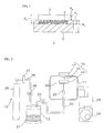
FIG. 2 is a schematic diagram illustrating the configuration of an aerosol deposition device used in a method for producing the metal oxide-polymer laminate shown inFIG. 1 . - As shown in
FIG. 1 , a metal oxide-polymer laminate 1 in one embodiment of the present invention includes apolymer layer 2, and a metal oxide layer 3 laminated on one side of thepolymer layer 2. - The
polymer layer 2 is formed generally into a flat plate. The metal oxide layer 3 extends into thepolymer layer 2 with an embeddedportion 4. The embeddedportion 4 is formed by metal oxide material being buried at various depths from the surface of thepolymer layer 2 within the thickness direction. The exposed part (non-embedded) of oxide layer 3 is formed on top of the embedded area in a continuation of the deposition (coating) process. - Examples of materials that form the
polymer layer 2 include thermoplastic resin and thermosetting resin. Preferably, thermoplastic resin is used. - Examples of the thermoplastic resin include olefin resins such as polyethylene and polypropylene; polyester resins such as polyethylene terephthalate (PET); fluorine resins such as polytetrafluoroethylene (tetrafluoroethylene resin, PTFE), a copolymer of tetrafluoroethylene and ethylene (ETFE), and a tetrafluoroethylene-perfluoroalkylvinylether copolymer (PFE); polyamide resins such as nylon; polyimide resins; polyvinyl chloride (PVC); silicone resin; and cellulose. Preferably, fluorine resins, and olefin resins are used. Of the fluorine resins, more preferably, polytetrafluoroethylene is used.
- Examples of the thermosetting resin include epoxy resin, phenol resin, amino resin, and unsaturated polyester resin.
- These can be used singly, or can be used in combination of two or more.
- The
polymer layer 2 may contain other organic compounds, for example, protein. - The
polymer layer 2 may be formed from a single layer, or may be formed from multiple layers. - The
polymer layer 2 is preferably a porous layer. Example of the porous layer include a porous membrane nonwoven fabric. When thepolymer layer 2 is a porous layer, the metal oxide layer 3 can be embedded reliably by an AD method to be described later. - When the
polymer layer 2 is nonwoven fabric, the production method is not particularly limited, and for example, can be produced by a dry method, wet method, spunbonding, thermal bonding, chemical bonding, stitch bonding, needle punching, melt blowing, spunlacing, steam jet method, and heat lamination method. - The
polymer layer 2 has thickness X1 of, for example, 1 µm or more, preferably 10 µm or more, more preferably 15 µm or more, and for example, 1000 µm or less, preferably 500 µm or less, more preferably 250 µm or less. - The embedded
portion 4 has depth (that is, the length in up-down direction where the metal oxide layer 3 to be described later is embedded in the thickness direction) X2 of, for example, 0.02 µm or more and 50 µm or less. In particular, when thepolymer layer 2 is composed of fluorine resin, the embeddedportion 4 depth, X2, should be preferably 0.1 µm or more, more preferably 0.5 µm or more, and preferably 5 µm or less, more preferably 3 µm or less. When thepolymer layer 2 is composed of olefin resin, preferably, depth X2 is 3 µm or more, more preferably 12 µm or more, and preferably, 30 µm or less, more preferably 20 µm or less. - The metal oxide layer 3 is generally formed into a flat plate, and is laminated on one side in the thickness direction of the
polymer layer 2. The metal oxide layer 3 is formed so as a portion is embedded/included in thepolymer layer 2 when projected in the thickness direction. - The metal oxide layer 3 is formed from metal oxide particles (metal oxide powder) by an aerosol deposition method (AD method).
- Examples of metals that form the metal oxide particles include zirconia (zirconium oxide), ceria (cerium oxide), alumina, yttria, tungsten oxide, and titanium oxide. Preferably, zirconia and ceria are used, and more preferably, zirconia is used.
- For these metal oxide powders, known or commercially available ones can be used. To be specific, for the zirconia powder, for example, "RC-100" (manufactured by DAIICHI KIGENSO KAGAKU KOGYO CO., LTD.) and "TZ-3Y-E" (manufactured by Tosoh Corporation) are used. Examples of alumina powder include "AL-160SG-3", "AS-160SG-4", and "AL-45-A" (all trade names, manufactured by Showa Denko K.K.). Examples of yttria powder include "DTS-Y35" (manufactured by Fujimi Incorporated.).
- These metal oxide powders may be used singly or in a combination of two or more.
- The metal oxide particles used in the coating process may be primary (single) particles, or may be formed from aggregates (secondary particles) of primary particles.
- Preferably, the metal oxide particles are formed from aggregates. This allows for excellent handleability, and reliable embedment of the metal oxide layer 3 in the
polymer layer 2 by the AD method. - The primary particles of the metal oxide particles have an average particle size of, for example, 30 nm or more, preferably 50 nm or more, and for example, 500 nm or less, preferably 300 nm or less.
- The average particle size of the primary particles of the metal oxide particles is measured by, for example, a scanning electron microscope (manufactured by Hitachi High-Technologies Corporation).
- The aggregates (secondary particles) of metal oxide particles have an average particle size (median diameter) of, for example, 0.5 µm or more, preferably 2 µm or more, and for example, 10 µm or less, preferably 5 µm or less. When the aggregates have an average particle size of below the above-described lower limit, there may be a case where the metal oxide layer 3 cannot be embedded in the
polymer layer 2 by the AD method. Meanwhile, when the aggregates have an average particle size of more than the above-described upper limit, the metal oxide particles sprayed by the AD method toward thepolymer layer 2 may fail to form the metal oxide layer 3, and may destroy thepolymer layer 2 due to excessively large kinetic energy of the impacting particle. - The average particle size (median diameter) of the metal oxide particles is measured with, for example, a scanning electron microscope (manufactured by Hitachi High-Technologies Corporation).
- The metal oxide layer 3 may contain a known additive other than the metal oxide particles. Examples of the additive include polymer powder. For example, 1.0 mass% or less, preferably 0.5 mass% or less, even more preferably 0 mass% of the additive may be contained relative to the total amount of metal oxide particles and additive mixture. It is recommended that the metal oxide layer 3 is preferably formed only from metal oxide material.
- Next, a production method of the metal oxide-
polymer laminate 1 is described in detail. - For the formation of the metal oxide-polymer laminate, first, a
polymer layer 2a is formed using known fabrication methods. At this point, no embeddedportion 4 is present in thepolymer layer 2a. - Next, in this method, an embedded
portion 4 and the metal oxide layer 3 are formed in a single deposition step using deposition method (AD method) (formation step). - To form the metal oxide layer 3 with the embedded
portion 4 by an aerosol deposition method (AD method-gas deposition method (vapor deposition method)), an aerosol deposition device 10 as shown inFIG. 2 is used. - The aerosol deposition device 10 includes a film-forming
chamber 11, anaerosol generation chamber 12, and a carriergas transportation device 13. - The film-forming
chamber 11 is the chamber where the formation of the metal oxide layer 3 on the surface of thepolymer layer 2a takes place, and includes asubstrate holder 14, a thermometer (not shown) for measuring the temperature in the film-formingchamber 11, and a pressure gauge (not shown) for measuring the pressure in the film-formingchamber 11. - The
substrate holder 14 includes asupport 15, amount 16, and a movingstage 17. - The
support 15 is provided to allow connection of the mount 16 (kept at working pressure) and the moving stage 17 (kept at atmospheric pressure). - The
mount 16 is provided for holding and fixing thepolymer layer 2a in the film-formingchamber 11 for film-forming the oxidation layer coating step. - The
stage 17 is provided so that thepolymer layer 2a can be moved in any direction (x direction (front-back direction), y direction (left-right direction), z direction (up-down direction), and 0 direction (rotational direction)) before or during the formation of the metal oxide layer 3. - In this fashion, the
stage 17 is connected to themount 16 through thesupport 15, and allows themount 16 to be movable. - The film-forming
chamber 11 is connected to amechanical booster pump 18 and arotary pump 19 for pressure adjustment purposes. - The
mechanical booster pump 18 and therotary pump 19 are sequentially connected to the film-formingchamber 11, so as to vacuum the film-formingchamber 11 as well as theaerosol chamber 12 that communicate with the film-formingchamber 11 through a connection pipe 20 (described later). - The
aerosol chamber 12 is a storage tank that contains the material that will form the metal oxide layer 3 (that is, metal oxide particles), and includes avibration device 21, and a pressure gauge (not shown) for measuring the pressure in theaerosol chamber 12. - The
vibration device 21 is a device that causes vibration in theaerosol chamber 12, and in the metal oxide material powder contained in it. Any known shaker can be used as thevibration device 21. - A
connection pipe 20 links theaerosol chamber 12 and the film-formingchamber 11. - The
connection pipe 20 is a pipe for transporting the aerosolized material (hereinafter referred to as aerosol) from theaerosol chamber 12 to the film-formingchamber 11, and is disposed so that one end portion (upstream-side end portion) is connected to theaerosol chamber 12, and the other end portion penetrates the bottom wall of the film-formingchamber 11 and extends toward themount 16. In the film-formingchamber 11, a film-formingnozzle 22 is connected to the end portion (downstream-side end portion) of theconnection pipe 20. - The film-forming
nozzle 22 is a spray device for spraying the aerosol to the surface of thepolymer layer 2a, and it is disposed in the film-formingchamber 11 so that the spray port (slit) is facing themount 16. To be specific, the film-formingnozzle 22 is disposed so that the spray port is located at a predetermined distance from the mount 16 (e.g., 1 mm or more, preferably 3 mm or more, and for example, 100 mm or less, preferably 50 mm or less). In this fashion, the aerosol supplied from theaerosol chamber 12 is sprayed on the surface of thepolymer layer 2a. - The shape of the spray port (slit opening length) of the film-forming
nozzle 22 is not particularly limited, and is set in accordance with, for example, the amount of aerosol to be sprayed and the spraying length or area. - A
valve 23 is provided on theconnection pipe 20. Examples of theconnection pipe valve 23 include, for example, a known valve such as a solenoid valve. - The
gas transportation device 13 includes agas cylinder 25. - The
gas cylinder 25 is a cylinder that contains a pressurized gas such as oxygen gas, helium gas, argon gas, nitrogen gas, or air; and is connected to theaerosol chamber 12 through thegas pipe 26. - The
gas pipe 26 is a pipe for transporting carrier gas from thecarrier gas cylinder 25 to theaerosol chamber 12, and its upstream-side end portion is connected to thecarrier gas cylinder 25, while its downstream-side end portion is connected to theaerosol chamber 12. - A
gas flowmeter 27 is installed on thegas pipe 26. Thegas flowmeter 27 is a device for adjusting the flow rate of the gas in thegas pipe 26. Without particular limitation, a known flowmeter is used. - A
gas pipe valve 28 is installed on thegas pipe 26 between thegas flowmeter 27 and the downstream side end portion of thegas pipe 26. For thegas pipe valve 28, for example, a known valve such as a solenoid valve is used. - To form the metal oxide layer 3 with the aerosol deposition device 10, first, the
polymer layer 2a is disposed on themount 16 so that the surface on which the metal oxide layer 3 is to be formed faces the film-forming nozzle 22 (lower side). - Meanwhile, the material (metal oxide particles, preferably, aggregates of metal oxide particles) of the metal oxide layer 3 as described above is introduced into the
aerosol chamber 12. - The aggregates can be formed by heating the primary particles of the metal oxide particles for a predetermined time.
- The heating temperature can be determined appropriately in accordance with, for example, the melting point and the primary particle size of the metal oxide, and is, for example, 700°C or more and 1500°C or less. Particularly, when zirconia is used for the metal oxide, the heating temperature is preferably 900°C or more, more preferably 950°C or more, even more preferably 1100°C or more, and preferably 1300°C or less, more preferably 1200°C or less. Furthermore, when ceria is used for the metal oxide, the heating temperature is preferably 750°C or more, more preferably 1000°C or more, and preferably 1300°C or less, more preferably 1200°C or less.
- The heating time is, for example, 0.1 hour or more, preferably 0.25 hour or more, and for example, 24 hours or less, preferably 1 hour or less.
- By adjusting the heating conditions as described above, aggregates having a desired particle size can be obtained.
- Next, in this method, the
gas pipe valve 28 is closed and theconnection pipe valve 23 is opened, and themechanical booster pump 18 and therotary pump 19 are driven, thereby vacuuming the film-formingchamber 11 and theaerosol chamber 12. - The pressure in the film-forming
chamber 11 is, for example, 5 to 80Pa, and the pressure in theaerosol chamber 12 is, for example, 5 to 80Pa. - Next, in this method, the material of the metal oxide layer 3 is vibrated in the
aerosol chamber 12 by thevibration device 21, thegas pipe valve 28 is opened, and the carrier gas is supplied to theaerosol chamber 12 from thecarrier gas cylinder 25 through theflowmeter 27. In this manner, the material of the metal oxide layer 3 can be aerosolized, and the generated aerosol can be transported to the film-formingnozzle 22 through theconnection pipe 20. - The flow rate of the carrier gas adjusted with the
gas flowmeter 27 is, for example, 1 L/min or more, preferably 3 L/min or more, and for example, 20 L/min or less, preferably 18 L/min or less. - Next, in this method, the material is sprayed from the spray port of the film-forming
nozzle 22 toward the surface of thepolymer layer 2a. - The pressure inside the
aerosol chamber 12 during the spraying of the aerosol is, for example, 50 Pa or more, preferably 1000 Pa or more, and for example, 80000 Pa or less, preferably 50000 Pa or less. - The pressure in the film-forming
chamber 11 is, for example, 10 Pa or more, preferably 30 Pa or more, and for example, 1000 Pa or less, preferably 800 Pa or less. - The temperature in the
aerosol chamber 12 during the spraying of the aerosol is, for example, 0 to 50°C. - During the spraying of the aerosol, preferably, the
stage 17 is moved suitably so that the aerosol is sprayed to the surface of thepolymer layer 2a evenly. - When moving the
stage 17, thestage 17 is moved at a speed of (that is, the moving speed of the film-forming nozzle 22), for example, 0.1 mm/sec or more, preferably, 0.2 mm/sec or more, and for example, 100 mm/sec or less, preferably 20 mm/sec or less. - When the material is sprayed toward the surface of the
polymer layer 2a, the material collides with the surface of thepolymer layer 2a. The result of the collision is the formation of the embeddedportion 4 in thepolymer layer 2a. When the material is an aggregate, the aggregate once breaks up into primary particles at the time of the collision, and then the primary particles are embedded in thepolymer layer 2a where the particles will consolidate, thereby forming the embeddedportion 4 of the metal oxide layer 3. After creation of the embeddedportion 4, the exposed part of the metal oxide layer 3 is formed onto thepolymer layer 2a in a similar way as the embeddedportion 4 but without the primary particles being subjected to an embedding process. - In this manner, the metal oxide layer 3 can be formed on the surface of the polymer layer 2 (lower side in the vertical direction). To be specific, a portion of the metal oxide layer 3 (one end portion in the thickness direction, to be specific, upper end portion) is embedded as embedded
portion 4 in thepolymer layer 2 in the thickness direction. - The metal oxide layer 3 has thickness X3 of, for example, 0.1 µm or more and 50 µm or less. Particularly, when the
polymer layer 2 on which the metal oxide layer 3 is laminated is fluorine resin, thickness X3 is preferably 0.3 µm or more, more preferably 0.8 µm or more, and preferably 10 µm or less, more preferably 5 µm or less. When thepolymer layer 2 is olefin resin, thickness X3 is preferably 1 µm or more, more preferably 12 µm or more, and preferably 25 µm or less, more preferably 20 µm or less. - Thickness X4 (that is, thickness deducting X2 from X3) at an exposure portion of the metal oxide layer 3 is, for example, 0.1 µm or more, preferably 0.3 µm or more, and for example, 20 µm or less, preferably 10 µm or less, more preferably less than 1.0 µm.
- Thus, in the resulting metal oxide-
polymer laminate 1, the metal oxide layer 3 is formed by the aerosol deposition method, and a portion of the metal oxide layer 3 is embedded in thepolymer layer 2 in the thickness direction, and therefore the metal oxide layer 3 is laminated onto thepolymer layer 2 firmly, and adherence between the metal oxide layer 3 and thepolymer layer 2 is excellent. In this fashion, defects in the metal oxide-polymer laminate 1 are reduced, and thus the production yield can be improved. Due to the strong adherence between layers, the metal oxide-polymer laminate 1 has excellent durability. - The metal oxide-
polymer laminate 1 can be used in various applications. For example, the metal oxide-polymer laminate 1 can be suitably used in applications such as substrates for electronic components, flexible electronic devices, electrooptic devices, sensor components, medical devices, and gas-liquid separation membranes. - Furthermore, by forming the metal oxide layer 3 on the
polymer layer 2 using aggregates of the metal oxide particles by AD method, the aggregates provide strong impact force on the surface of thepolymer layer 2, and thus modify the surface of thepolymer layer 2 by etching and/or surface plastic deformation and elastic recovery of surface asperities, thereby reliably providing the embeddedportion 4. The aggregates break up into primary particles during collision with the surface of thepolymer layer 2, and thereafter, the primary particles are consolidated again to form the metal oxide layer 3. In this manner, a highly coherent metal oxide-polymer laminate 1 can be obtained. - In the embodiment of
FIG. 1 , a portion of the metal oxide layer 3 is embedded in thepolymer layer 2 as embeddedportion 4; however, for example, although not shown, the metal oxide layer 3 can be embedded entirely in thepolymer layer 2 as embeddedportion 4 as well. - In the embodiment of
FIG. 1 , although the metal oxide layer 3 is formed at the center portion of thepolymer layer 2 when viewed from the top, for example, the metal oxide layer 3 can also be formed at an end edge portion of thepolymer layer 2 when viewed from the top. - In the embodiment of
FIG. 1 , the metal oxide layer 3 is laminated only on one side of thepolymer layer 2; however, although not shown, the metal oxide layer 3 can also be laminated on both sides (one side and the other side) of thepolymer layer 2. The lamination of the oxide layer on both sides of thepolymer layer 2 is achieved using the same approach as for one side (surface) lamination and the same results as those of the embodiment shown inFig.1 are achieved. - In the embodiment of
FIG. 1 , thepolymer layer 2 is formed generally into a flat plate having a straight line; however, thepolymer layer 2 can also be formed to have a curved shape (convex or concave in thickness direction). - These embodiments also achieve the same operations and effects as those of the embodiment shown in
FIG. 1 . - In the following text, the present invention is described in further detail with reference to Examples and Comparative Examples. The embodiments described below are not intended to limit the invention to the precise forms disclosed as examples. Rather, a purpose of these examples is to facilitate the appreciation and understanding by others skilled in the art of the principles and practices of the present invention. The numerical examples of which are shown below may be substituted to any value within the limits described in the above embodiments.
- A polytetrafluoroethylene resin porous film (PTFE: "TEMISH", 7 cm × 7 cm, thickness 80 µm, manufactured by Nitto Denko Corporation) was prepared as a
polymer layer 2a. - Then, the film (
polymer layer 2a) was set on themount 16 as indicated inFig.2 . The temperature inside the film-forming chamber was 22°C and the gas selected for the layer fabrication process was nitrogen gas. - The distance between the spray port of the
nozzle 22 and the surface of thepolymer layer 2a was adjusted to be 15 mm. - Meanwhile, zirconia powder (trade name "RC-100", average particle size of primary particles 0.2 µm, manufactured by DAIICHI KIGENSO KAGAKU KOGYO CO., LTD.) was heated at 1175°C for 0.5 hours, thereby producing aggregates of zirconia powder (
median diameter 2 µm). The median diameter of the aggregates of zirconia powder was measured with a scanning electron microscope (trade name "S-3400N", manufactured by Hitachi High-Technologies Corporation) at a magnification of 5000 times. - The aggregates were prepared in an amount of 50 g, and introduced into a 450mL glass-made aerosol chamber.
- Thereafter, the gas pipe valve was closed and the connection pipe valve was opened, and the mechanical booster pump and the rotary pump were driven, thereby reducing the pressure inside the film-forming chamber and the aerosol chamber to 50 Pa.
- Then, the flow rate of the nitrogen gas was adjusted to be 6 L/min with the
gas flowmeter 27, and, while shaking the aerosol chamber with a shaker, thegas pipe valve 23 was opened. In this manner, the zirconia powder was aerosolized in the aerosol chamber, and the obtained aerosol was sprayed from the nozzle. - The pressure in the film-forming chamber at this time was 250Pa.
- Then, the mount to which the
polymer layer 2a was fixed was moved in x-y direction at a moving speed of 12 mm/sec, and the aerosol was sprayed toward the surface of thepolymer layer 2a from the nozzle. - In this manner, as shown in
FIG. 1 , the metal oxide layer 3 (5 cm × 5 cm, thickness 1.4 µm) was laminated on the surface of thepolymer layer 2 so that a portion of the metal oxide layer 3 in the thickness direction was embedded into thepolymer layer 2a, thereby producing a metal oxide-polymer laminate 1. Depth X2 (length in up-down direction of the portion where the metal oxide layer 3 (zirconia layer) was embedded) of the embeddedportion 4 was 0.9 µm. - Metal oxide-
polymer laminates 1 were obtained in the same manner as in Example 1, except that the average particle size (median diameter) of the aggregates of zirconia powder was changed in accordance with Table 1. - In Example 2, the zirconia powder was heated at 1050°C for 0.5 hours, thereby adjusting the average particle size of the aggregates of zirconia powder. In Example 3, the zirconia powder was heated at 1175°C for 1 hour, thereby adjusting the average particle size of the aggregates. In Example 4, the zirconia powder was heated at 1175°C for 3 hours, thereby adjusting the average particle size of the aggregates.
- A metal oxide-
polymer laminate 1, in which a portion of the metal oxide layer 3 (5 cm × 5 cm, thickness 20.6 µm) was embedded near the surface of thepolymer layer 2a in the thickness direction, was obtained in the same manner as in Example 1, except that polypropylene nonwoven fabric (PP: trade name "HOP60HCF", manufactured by Nitto Denko Corporation, 7 cm × 7 cm, thickness 200 µm, heat lamination method) was prepared as thepolymer layer 2. - A metal oxide-
polymer laminate 1 was obtained in the same manner as in Example 5, except that the average particle size (median diameter) of the aggregates of zirconia powder was changed in accordance with Table 2. - In Example 6, the zirconia powder was heated at 1050°C for 0.5 hours, thereby adjusting the average particle size of the aggregates of zirconia powder. In Example 7, the zirconia powder was heated at 1175°C for 1 hour, thereby adjusting the average particle size of the aggregates. In Example 8, the zirconia powder was heated at 1175°C for 3 hours, thereby adjusting the average particle size of the aggregates.
- A metal oxide-
polymer laminate 1, in which a portion of the metal oxide layer 3 (5 cm × 5 cm,thickness 17 µm) was embedded near the surface of thepolymer layer 2a in the thickness direction, was obtained in the same manner as in Example 5, except that ceria powder (average particle size of primary particle 50 nm) was heated at 800°C for 3 hours, thereby producing aggregates of ceria powder (median diameter 3 µm) and that the aggregates were used. - A metal oxide-
polymer laminate 1 was obtained in the same manner as in Example 9, except that the average particle size of the aggregates of ceria powder (median diameter) was changed in accordance with Table 3. In Example 10, the ceria powder was heated at 1050°C for 0.5 hours, thereby adjusting the average particle size of the aggregates of ceria powder. - Zirconia powder formed from primary particles (average particle size 0.2 µm) in an amount of 10 g was dispersed in 44 g of a solvent (1-methyl-2-pyrrolidone), and polyvinylidene fluoride was added as a binder to be 2.5 mass% in the material after solvent removal, thereby preparing a zirconia dispersion liquid.
- The zirconia dispersion liquid was laminated on the surface of a fluorinated ethylene resin porous film (same as the above-described one) by spin coating (150 rpm, 10 seconds), and dried at 90°C for 1 day.
- The metal oxide-
polymer laminate 1 was obtained in this manner. The laminated metal oxide layer had a size of 2 cm × 2 cm, and a thickness of 2.3 µm. - The zirconia dispersion liquid was laminated on the surface of the fluorinated ethylene resin porous film by spin coating, and dried in the same manner as in Comparative Example 1, except that the zirconia powder formed from primary particles in the dispersion liquid was changed with zirconia powder formed from aggregates of primary particles (
median diameter 2 µm) used in Example 1. - The metal oxide-
polymer laminates 1 of Examples and Comparative Examples were subjected to an ultrasonic cleaning to verify the integrity of the laminates. The ultrasonic cleaner was operated under room temperature (25°C) for 3 minutes. - The mass of only the metal oxide layer 3 before and after the ultrasonic cleaning was measured, and the mass decrease rate of the metal oxide layer 3 after the ultrasonic cleaning procedure relative to the mass of the metal oxide layer 3 before the ultrasonic cleaning was calculated. The results are shown in Tables 1 to 3.
-
[Table 1] Example 1 Example 2 Example 3 Example 4 Metal Oxide Powder Material Zirconia Zirconia Zirconia Zirconia Median Diameter (µm) 2 1 5 8 Polymer layer Material PTFE porous film PTFE porous film PTFE porous film PTFE porous film Thickness X1 (µm) 80 80 80 80 Metal oxide layer thickness X3 (µm) 1.4 0.5 1.7 0.5 Embedment portion depth X2 (µm) 0.9 0.3 1.2 0.3 Metal oxide layer exposure portion thickness X4 (µm) 0.5 0.2 0.5 0.2 Mass decrease rate (%) 0 3 0 3 [Table 2] Example 5 Example 6 Example 7 Example 8 Metal Oxide Powder Material Zirconia Zirconia Zirconia Zirconia Median Diameter (µm) 2 1 5 8 Polymer layer Material PP nonwoven fabric PP nonwoven fabric PP nonwoven fabric PP nonwoven fabric Thickness X1 (µm) 200 200 200 200 Metal oxide layer thickness X3 (µm) 20.6 10.2 20.6 10.2 Embedment portion depth X2 (µm) 20 10 20 10 Metal oxide layer exposure portion thickness X4 (µm) 0.6 0.2 0.6 0.2 Mass decrease rate (%) 0 3 0 3 [Table 3] Example 9 Example 10 Comparative Ex. 1 Comparative Ex. 2 Metal Oxide Powder Material Ceria Ceria Zirconia Zirconia Median Diameter (µm) 3 8 0.2 2 Polymer layer Material PP nonwoven fabric PP nonwoven fabric PTFE porous film PTFE porous film Thickness X1 (µm) 200 200 80 80 Metal oxide layer thickness X3 (µm) 17 14.7 2.3 20 Embedment portion depth X2 (µm) 16 14 0.3 0 Metal oxide layer exposure portion thickness X4 (µm) 1.0 0.7 2.0 20 Mass decrease rate (%) 3 0 80 95 - As will be understood by those familiar with the art, the descriptions and disclosures therein are intended for illustrative purpose only and not limiting in any manner the scope of the invention. Modifications and variations of the present invention that will be obvious to those skilled in the art are to be covered by the following claims.
Claims (5)
- A metal oxide-polymer laminate comprising:a polymer layer, anda metal oxide layer laminated on a surface of the polymer layer and formed by an aerosol deposition method,wherein at least a portion of the metal oxide layer is embedded in the polymer layer in a thickness direction thereof.
- The metal oxide-polymer laminate according to Claim 1, wherein the metal oxide layer is formed by the aerosol deposition method using an aggregate of metal oxide particles.
- The metal oxide-polymer laminate according to Claim 2, wherein the aggregate of metal oxide particles has a median diameter of 0.5 µm or more and 10 µm or less.
- The metal oxide-polymer laminate according to Claim 1, wherein the polymer layer is a porous layer.
- A method for producing a metal oxide-polymer laminate, the method comprising:preparing a polymer layer, andforming a metal oxide layer on a surface of the polymer layer by an aerosol deposition method so that at least a portion of the metal oxide layer is embedded in the polymer layer in a thickness direction thereof.
Applications Claiming Priority (1)
| Application Number | Priority Date | Filing Date | Title |
|---|---|---|---|
| JP2013244625A JP6255222B2 (en) | 2013-11-27 | 2013-11-27 | Metal oxide-polymer laminate and method for producing the same |
Publications (1)
| Publication Number | Publication Date |
|---|---|
| EP2878703A1 true EP2878703A1 (en) | 2015-06-03 |
Family
ID=52100991
Family Applications (1)
| Application Number | Title | Priority Date | Filing Date |
|---|---|---|---|
| EP14194470.2A Withdrawn EP2878703A1 (en) | 2013-11-27 | 2014-11-24 | Metal oxide-polymer laminate and production method thereof |
Country Status (5)
| Country | Link |
|---|---|
| US (2) | US20150147565A1 (en) |
| EP (1) | EP2878703A1 (en) |
| JP (1) | JP6255222B2 (en) |
| KR (1) | KR20150061589A (en) |
| CN (1) | CN104669733A (en) |
Cited By (1)
| Publication number | Priority date | Publication date | Assignee | Title |
|---|---|---|---|---|
| KR20190007487A (en) * | 2016-05-16 | 2019-01-22 | 고쿠리츠켄큐카이하츠호진 상교기쥬츠 소고켄큐쇼 | Laminated structure and method of making the same |
Families Citing this family (1)
| Publication number | Priority date | Publication date | Assignee | Title |
|---|---|---|---|---|
| US9872399B1 (en) * | 2016-07-22 | 2018-01-16 | International Business Machines Corporation | Implementing backdrilling elimination utilizing anti-electroplate coating |
Citations (7)
| Publication number | Priority date | Publication date | Assignee | Title |
|---|---|---|---|---|
| WO2002047898A1 (en) * | 2000-12-12 | 2002-06-20 | Brogan Jeffrey A | Non-skid coating and method of forming the same |
| DE102004038795A1 (en) * | 2004-08-09 | 2006-03-02 | Ballhorn, Reinhard, Dr. | Production of photocatalytically active polymer surfaces of variable composition comprises cold gas spraying them with oxide powder to produce adherent photocatalytic layer |
| JP2006128229A (en) | 2004-10-26 | 2006-05-18 | Murata Mfg Co Ltd | Composite multilayer board |
| US20070110919A1 (en) * | 2005-11-15 | 2007-05-17 | ATG Advanced Technology Group s.r.o. | Method for producing photocatalytically active polymers |
| US7547393B2 (en) | 2005-12-07 | 2009-06-16 | General Electric Company | Membrane structure and method of making |
| JP2012216684A (en) | 2011-03-31 | 2012-11-08 | Nippon Zeon Co Ltd | Composite multilayer substrate |
| US20130280414A1 (en) * | 2010-12-15 | 2013-10-24 | Fuchita Nanotechnology Ltd. | Deposition method |
Family Cites Families (13)
| Publication number | Priority date | Publication date | Assignee | Title |
|---|---|---|---|---|
| JPS59145219A (en) * | 1983-02-04 | 1984-08-20 | Nippon Pillar Packing Co Ltd | Surface treatment of fluorine-containing high-molecular compound |
| US6004667A (en) * | 1994-06-30 | 1999-12-21 | Shinshu Ceramics Company, Ltd. | Low temperature melt injected anti-microbial films, articles containing such films and methods of manufacture and use thereof |
| JP3265481B2 (en) * | 1999-04-23 | 2002-03-11 | 独立行政法人産業技術総合研究所 | Low temperature molding of brittle material ultrafine particles |
| US6531187B2 (en) | 1999-04-23 | 2003-03-11 | Agency Of Industrial Science And Technology | Method of forming a shaped body of brittle ultra fine particles with mechanical impact force and without heating |
| KR100531295B1 (en) * | 2003-07-16 | 2005-11-28 | 엘지전자 주식회사 | Single panel projection device |
| JP2005274260A (en) * | 2004-03-24 | 2005-10-06 | Fuji Photo Film Co Ltd | Method for manufacturing photoconductive layer constituting radiation imaging panel |
| JP5401805B2 (en) * | 2008-02-29 | 2014-01-29 | 富士通株式会社 | Deposition method |
| JP2009301825A (en) * | 2008-06-12 | 2009-12-24 | Panasonic Corp | Nonaqueous electrolyte secondary battery and electrode used for the same, and method of manufacturing them |
| JP5252380B2 (en) * | 2008-07-14 | 2013-07-31 | Toto株式会社 | Composite structure and manufacturing method thereof |
| US8247050B2 (en) * | 2009-06-02 | 2012-08-21 | Integran Technologies, Inc. | Metal-coated polymer article of high durability and vacuum and/or pressure integrity |
| WO2011057341A1 (en) * | 2009-11-11 | 2011-05-19 | Nano-Nouvelle Pty Ltd | Porous materials |
| US20120237789A1 (en) * | 2011-02-15 | 2012-09-20 | Integran Technologies Inc. | High yield strength lightweight polymer-metal hybrid articles |
| CN103551171A (en) * | 2013-10-23 | 2014-02-05 | 三棵树涂料股份有限公司 | Aluminum phosphate coated photocatalytic nano titanium dioxide powder and application thereof |
-
2013
- 2013-11-27 JP JP2013244625A patent/JP6255222B2/en not_active Expired - Fee Related
-
2014
- 2014-11-21 CN CN201410674343.6A patent/CN104669733A/en active Pending
- 2014-11-24 EP EP14194470.2A patent/EP2878703A1/en not_active Withdrawn
- 2014-11-25 US US14/553,286 patent/US20150147565A1/en not_active Abandoned
- 2014-11-26 KR KR1020140166056A patent/KR20150061589A/en not_active Ceased
-
2016
- 2016-07-14 US US15/209,944 patent/US10415132B2/en not_active Expired - Fee Related
Patent Citations (7)
| Publication number | Priority date | Publication date | Assignee | Title |
|---|---|---|---|---|
| WO2002047898A1 (en) * | 2000-12-12 | 2002-06-20 | Brogan Jeffrey A | Non-skid coating and method of forming the same |
| DE102004038795A1 (en) * | 2004-08-09 | 2006-03-02 | Ballhorn, Reinhard, Dr. | Production of photocatalytically active polymer surfaces of variable composition comprises cold gas spraying them with oxide powder to produce adherent photocatalytic layer |
| JP2006128229A (en) | 2004-10-26 | 2006-05-18 | Murata Mfg Co Ltd | Composite multilayer board |
| US20070110919A1 (en) * | 2005-11-15 | 2007-05-17 | ATG Advanced Technology Group s.r.o. | Method for producing photocatalytically active polymers |
| US7547393B2 (en) | 2005-12-07 | 2009-06-16 | General Electric Company | Membrane structure and method of making |
| US20130280414A1 (en) * | 2010-12-15 | 2013-10-24 | Fuchita Nanotechnology Ltd. | Deposition method |
| JP2012216684A (en) | 2011-03-31 | 2012-11-08 | Nippon Zeon Co Ltd | Composite multilayer substrate |
Non-Patent Citations (1)
| Title |
|---|
| D HANFT ET AL: "An Overview of the Aerosol Deposition Method: Process Fundamentals and New Trends in Materials Applications", J. CERAM. SCI. TECH, 1 January 2015 (2015-01-01), pages 147 - 182, XP055451100, Retrieved from the Internet <URL:https://www.ceramic-science.com/php/article_pdf.php?article_id=100390&hash=0c3d15f32e> DOI: 10.4416/JCST2015-00018 * |
Cited By (2)
| Publication number | Priority date | Publication date | Assignee | Title |
|---|---|---|---|---|
| KR20190007487A (en) * | 2016-05-16 | 2019-01-22 | 고쿠리츠켄큐카이하츠호진 상교기쥬츠 소고켄큐쇼 | Laminated structure and method of making the same |
| EP3459729A4 (en) * | 2016-05-16 | 2020-01-22 | National Institute of Advanced Industrial Science and Technology | MULTILAYER STRUCTURE AND METHOD FOR PRODUCING THE SAME |
Also Published As
| Publication number | Publication date |
|---|---|
| US20150147565A1 (en) | 2015-05-28 |
| JP6255222B2 (en) | 2017-12-27 |
| US20160319420A1 (en) | 2016-11-03 |
| KR20150061589A (en) | 2015-06-04 |
| JP2015101042A (en) | 2015-06-04 |
| US10415132B2 (en) | 2019-09-17 |
| CN104669733A (en) | 2015-06-03 |
Similar Documents
| Publication | Publication Date | Title |
|---|---|---|
| JP2018129539A (en) | Manufacturing method of electrostatic chuck and electrostatic chuck | |
| JP5565673B2 (en) | Mist etching apparatus and mist etching method | |
| JP2011042856A (en) | Film deposition device and film deposition method | |
| KR101079258B1 (en) | Manufacturing method of ceramic polymer complex, and ceramic polymer complex using the method | |
| KR20200114363A (en) | High-sensitive flexible strain sensor based on direct-printing of mixture of metal nano particles and carbon nano tubes amd manufacturing method thereof | |
| US10415132B2 (en) | Metal oxide-polymer laminate and production method thereof | |
| CN109295451B (en) | Plasma-assisted aerosol deposition film-forming method and aerosol deposition device | |
| KR20180115812A (en) | Composite porous film for fluid separation, production method thereof, and filter | |
| KR102681355B1 (en) | Discharging device, molding device, and method of manufacturing molded body | |
| KR20220077222A (en) | Barrier film manufacturing method containing cellulose nanofibers | |
| US20230330947A1 (en) | Method of manufacturing composite member and the composite member | |
| KR101974642B1 (en) | Superhydrophobic porous membrane structure for underwater air layer holding and its method of fabrication | |
| JP5656036B2 (en) | Composite structure | |
| KR100965024B1 (en) | Powder coating method and apparatus | |
| JP5401960B2 (en) | Film forming method and film forming apparatus | |
| KR102201402B1 (en) | Manufacturing method of chipless rfid tag based on direct-printing of nano particles and carbon nano tubes mixture, and rfid tag manufactured by the same | |
| Lee et al. | Fabrication of nickel micromesh sheets and evaluation of their water-repellent and water-proof abilities | |
| JP2008088451A (en) | Film forming method and film forming apparatus | |
| JP4553630B2 (en) | Film forming apparatus and film forming method | |
| KR100839775B1 (en) | Coating nozzle and manufacturing method of the nozzle | |
| KR102220056B1 (en) | Apparatus for supplying powder and system for coating equipment with the apparatus | |
| JP2009209413A (en) | Method for selecting optimum condition for execution of aerosol deposition method, and film forming method | |
| Huang et al. | Fabrication of superhydrophobic surface with discarded silicone under arc exposure | |
| KR20180111248A (en) | Patterning method of vacuum kinetic spray process | |
| KR102661440B1 (en) | Deposition device for glass coatining and method thereof |
Legal Events
| Date | Code | Title | Description |
|---|---|---|---|
| PUAI | Public reference made under article 153(3) epc to a published international application that has entered the european phase |
Free format text: ORIGINAL CODE: 0009012 |
|
| 17P | Request for examination filed |
Effective date: 20141124 |
|
| AK | Designated contracting states |
Kind code of ref document: A1 Designated state(s): AL AT BE BG CH CY CZ DE DK EE ES FI FR GB GR HR HU IE IS IT LI LT LU LV MC MK MT NL NO PL PT RO RS SE SI SK SM TR |
|
| AX | Request for extension of the european patent |
Extension state: BA ME |
|
| R17P | Request for examination filed (corrected) |
Effective date: 20151014 |
|
| RBV | Designated contracting states (corrected) |
Designated state(s): AL AT BE BG CH CY CZ DE DK EE ES FI FR GB GR HR HU IE IS IT LI LT LU LV MC MK MT NL NO PL PT RO RS SE SI SK SM TR |
|
| STAA | Information on the status of an ep patent application or granted ep patent |
Free format text: STATUS: EXAMINATION IS IN PROGRESS |
|
| 17Q | First examination report despatched |
Effective date: 20180305 |
|
| STAA | Information on the status of an ep patent application or granted ep patent |
Free format text: STATUS: THE APPLICATION IS DEEMED TO BE WITHDRAWN |
|
| 18D | Application deemed to be withdrawn |
Effective date: 20210112 |