EP2878475B1 - Nutzfahrzeuganhänger, insbesondere Sattelauflieger, und Nutzfahrzeuggespann - Google Patents
Nutzfahrzeuganhänger, insbesondere Sattelauflieger, und Nutzfahrzeuggespann Download PDFInfo
- Publication number
- EP2878475B1 EP2878475B1 EP14185124.6A EP14185124A EP2878475B1 EP 2878475 B1 EP2878475 B1 EP 2878475B1 EP 14185124 A EP14185124 A EP 14185124A EP 2878475 B1 EP2878475 B1 EP 2878475B1
- Authority
- EP
- European Patent Office
- Prior art keywords
- gas
- commercial vehicle
- vehicle trailer
- control module
- gas valve
- Prior art date
- Legal status (The legal status is an assumption and is not a legal conclusion. Google has not performed a legal analysis and makes no representation as to the accuracy of the status listed.)
- Active
Links
Images


Classifications
-
- B—PERFORMING OPERATIONS; TRANSPORTING
- B60—VEHICLES IN GENERAL
- B60K—ARRANGEMENT OR MOUNTING OF PROPULSION UNITS OR OF TRANSMISSIONS IN VEHICLES; ARRANGEMENT OR MOUNTING OF PLURAL DIVERSE PRIME-MOVERS IN VEHICLES; AUXILIARY DRIVES FOR VEHICLES; INSTRUMENTATION OR DASHBOARDS FOR VEHICLES; ARRANGEMENTS IN CONNECTION WITH COOLING, AIR INTAKE, GAS EXHAUST OR FUEL SUPPLY OF PROPULSION UNITS IN VEHICLES
- B60K15/00—Arrangement in connection with fuel supply of combustion engines or other fuel consuming energy converters, e.g. fuel cells; Mounting or construction of fuel tanks
- B60K15/03—Fuel tanks
- B60K15/03006—Gas tanks
-
- B—PERFORMING OPERATIONS; TRANSPORTING
- B60—VEHICLES IN GENERAL
- B60K—ARRANGEMENT OR MOUNTING OF PROPULSION UNITS OR OF TRANSMISSIONS IN VEHICLES; ARRANGEMENT OR MOUNTING OF PLURAL DIVERSE PRIME-MOVERS IN VEHICLES; AUXILIARY DRIVES FOR VEHICLES; INSTRUMENTATION OR DASHBOARDS FOR VEHICLES; ARRANGEMENTS IN CONNECTION WITH COOLING, AIR INTAKE, GAS EXHAUST OR FUEL SUPPLY OF PROPULSION UNITS IN VEHICLES
- B60K15/00—Arrangement in connection with fuel supply of combustion engines or other fuel consuming energy converters, e.g. fuel cells; Mounting or construction of fuel tanks
- B60K15/03—Fuel tanks
- B60K15/063—Arrangement of tanks
- B60K15/067—Mounting of tanks
- B60K15/07—Mounting of tanks of gas tanks
-
- B—PERFORMING OPERATIONS; TRANSPORTING
- B60—VEHICLES IN GENERAL
- B60K—ARRANGEMENT OR MOUNTING OF PROPULSION UNITS OR OF TRANSMISSIONS IN VEHICLES; ARRANGEMENT OR MOUNTING OF PLURAL DIVERSE PRIME-MOVERS IN VEHICLES; AUXILIARY DRIVES FOR VEHICLES; INSTRUMENTATION OR DASHBOARDS FOR VEHICLES; ARRANGEMENTS IN CONNECTION WITH COOLING, AIR INTAKE, GAS EXHAUST OR FUEL SUPPLY OF PROPULSION UNITS IN VEHICLES
- B60K15/00—Arrangement in connection with fuel supply of combustion engines or other fuel consuming energy converters, e.g. fuel cells; Mounting or construction of fuel tanks
- B60K15/03—Fuel tanks
- B60K15/03006—Gas tanks
- B60K2015/03026—Gas tanks comprising a valve
-
- B—PERFORMING OPERATIONS; TRANSPORTING
- B60—VEHICLES IN GENERAL
- B60Y—INDEXING SCHEME RELATING TO ASPECTS CROSS-CUTTING VEHICLE TECHNOLOGY
- B60Y2200/00—Type of vehicle
- B60Y2200/10—Road Vehicles
- B60Y2200/14—Trucks; Load vehicles, Busses
- B60Y2200/147—Trailers, e.g. full trailers or caravans
-
- B—PERFORMING OPERATIONS; TRANSPORTING
- B60—VEHICLES IN GENERAL
- B60Y—INDEXING SCHEME RELATING TO ASPECTS CROSS-CUTTING VEHICLE TECHNOLOGY
- B60Y2200/00—Type of vehicle
- B60Y2200/10—Road Vehicles
- B60Y2200/14—Trucks; Load vehicles, Busses
- B60Y2200/148—Semi-trailers, articulated vehicles
Definitions
- the invention relates to a commercial vehicle trailer, in particular semi-trailer, and a utility vehicle combination with such a commercial vehicle trailer.
- a commercial vehicle trailer of the type mentioned is, for example, from going back to the applicant DE 10 2011 056 921 A1 known.
- the known commercial vehicle trailer comprises a gas tank for storing natural gas or LPG, which is connectable by a gas line with a towing vehicle.
- the drive motor of the towing vehicle can be operated by the gas stored in the gas tank of the commercial vehicle trailer to increase the range of gas-powered commercial vehicles.
- the gas line extends at least in sections along the commercial vehicle trailer.
- the gas tanks have in practice gas valves that can regulate the gas supply to the towing vehicle by opening and closing.
- a power supply is required, which is currently done by their own power supply lines that extend along the commercial vehicle trailer and connectable via a connection panel on the front of the commercial vehicle trailer with a power source or voltage source of the towing vehicle. It has been found that the additional cable routing along the commercial vehicle trailer is complex, increases the assembly effort and complicates the retrofitting of existing commercial vehicle trailers with a gas tank.
- Another commercial vehicle trailer is from the DE 20 2012 103 321 U1 known.
- the object of the invention is to further develop the known commercial vehicle trailer such that the assembly costs are reduced and the retrofitting capability is improved. It is another object of the invention to increase the reliability and security of supply of a gas tank system on a commercial vehicle trailer. Finally, the object of the invention is to provide a commercial vehicle combination with such a commercial vehicle trailer.
- the invention is based on the idea to provide a commercial vehicle trailer, in particular semitrailer, with a brake system and with at least one gas tank, which is fluid-connectable by a gas line with a drive motor of a towing vehicle.
- the gas line extends at least in sections along the commercial vehicle trailer.
- the gas line is connected to an electrically operable gas valve of the gas tank, which is electrically coupled to a power supply output of a brake control module of the brake system.
- various interfaces are provided on a brake control module, wherein usually at least one power supply output is not assigned.
- This can be used to provide the power supply to the gas valves of the gas tanks.
- the brake control module is preferably part of the brake system of the commercial vehicle trailer, in particular an electronic brake system (EBS). Therefore, the brake control module is already arranged on the commercial vehicle trailer.
- EBS electronic brake system
- the electrical connection of the gas valves to the power supply output of the brake control module, the laying of a power supply line along the commercial vehicle trailer is avoided up to a junction for connection to the power-supplying towing vehicle. This saves additional installation effort, reduces material and component costs and facilitates the retrofitting of existing commercial vehicle trailers.
- the gas tank is preferably arranged directly below or between frame parts of the vehicle frame, so that short line lengths and thus material savings are made possible by the arrangement of the brake control module on the vehicle frame.
- the gas tank can be arranged below the brake control module.
- a tank module is provided with a plurality of gas tanks.
- the commercial vehicle trailer may have a tank module comprising a plurality of gas tanks.
- the tank module is preferably fastened to the vehicle frame of the commercial vehicle trailer.
- Each gas tank of the tank module preferably has its own gas valve.
- the use of a tank module with multiple gas tanks further simplifies assembly and simplifies retrofitting an existing commercial vehicle trailer.
- the tank module can be easily and quickly removed for maintenance of the commercial vehicle trailer, the electrical connections are easy to disconnect.
- a switching relay is arranged between the power supply output and the gas valve or the gas valves.
- the switching relay provides a simple and low-maintenance way to operate the gas valve.
- the switching relays may each have an operating current input, an operating current output and a switching current output.
- the operating current input is preferably electrically connected to the power supply output of the brake control module or an operating current output of a series-connected switching relay.
- the series connection of the switching relay with respect to the operating current for the gas valves additional power supply lines can be saved.
- the switching current output may be electrically connected to a gas valve.
- the switching relays are activated by a control signal and, when activated, provide a current connection between the power supply output of the Brake control module and the switching current output, so that the gas valve is supplied with an operating current.
- the gas valve control module has a power supply input.
- the power supply input may be electrically connected to the power supply output of the brake control module.
- the gas valve control module may further include a switching current output for connection to the gas valve such that the opening and closing of the gas valve is controllable by the gas valve control module.
- the gas valve control module preferably comprises an electronic control circuit.
- the gas valve control module may have a sensor input which is signal-connected or signal-connectable with at least one sensor, in particular a pressure sensor and / or volume flow sensor, wherein the sensor is arranged on the gas tank or in the gas line. In this way, the gas supply of the tractor can be monitored from the gas tanks.
- the brake control module and / or the switching relay and / or the gas valve control module has a control signal input, in particular a CAN bus interface.
- the control signal input is preferably signal-connected or signal-connectable with an engine control of the towing vehicle, so that the opening and closing of the gas valve can be controlled as a function of an operating state of the drive motor of the towing vehicle.
- the operating state of the gas valve can be controlled based on engine data of the drive motor of the towing vehicle via the control signal input. This represents a safe and flexible control of the gas valves.
- an electronic control module for example, the brake control module or the gas valve control module
- a bidirectional communication so that, for example, the switching position of the gas valve can be displayed via an indicator in the towing vehicle.
- a feedback of the switching state to the engine control of the towing vehicle is possible.
- the gas valve control module is preferably arranged on the tank module in the commercial vehicle trailer according to the invention.
- the tank module thus forms a compact unit, all essential components of the gas system are combined in the tank module. This facilitates the retrofitting, maintenance and installation of the tank module on the commercial vehicle trailer.
- the power supply output can be designed as a permanent plus output.
- the power supply output has an electrical voltage of 12 V or 24 V.
- Such a power supply output can be used directly to supply the gas valves, in particular without additional voltage converter or the like components.
- the invention is based on the idea to provide a commercial vehicle trailer, in particular semitrailer, with at least two gas tanks, which are fluid-connectable by a gas line with a drive motor of a towing vehicle and each having an electrically actuable gas valve.
- the gas line preferably extends along the utility vehicle trailer and is connected to each gas valve.
- at least two electrical fuses are provided, each gas valve being protected by its own electrical fuse.
- the individual protection of the gas valves has the advantage that even in case of malfunction of a gas valve, the gas supply of the towing vehicle is ensured. This increases the security of supply, i. The towing vehicle will continue to be supplied with gas even malfunction of a single valve. An interruption of the fuel supply is avoided. In addition, the reliability of the gas system is increased, since individual gas valves simply shut down in case of malfunction or the power supply can be interrupted.
- the fuses of the gas valves are arranged in a terminal box of an end wall of the commercial vehicle trailer. This facilitates access to the fuses and increases the ease of maintenance.
- the fuses of the gas valves may be arranged on a tank module comprising the gas tanks.
- the tank module forms a compact unit and is easy to install, since no additional cables are routed to the terminal box.
- gas tank of the commercial vehicle trailer is preferably fluidly connected to the drive motor of the towing vehicle, so that gas stored in the gas tank, in particular natural gas or LPG, is continuously supplied to the towing vehicle as fuel.
- the commercial vehicle combination according to the invention enables a low-emission operation of towing vehicles through the use of LPG or natural gas, with the additional equipment of the commercial vehicle trailer with gas tanks, the range of the entire utility vehicle combination is significantly increased. This makes such commercial vehicle combination also attractive for long distance transport.
- the figures explained in more detail below each show a commercial vehicle trailer 10, in particular a semi-trailer.
- the commercial vehicle trailer 10 is connectable to a towing vehicle 20, for example by a fifth wheel.
- the towing vehicle 20 has a motor controller 21, which comprises current and signal connections.
- the commercial vehicle trailer 10 has a brake system that includes a brake control module 18.
- the brake control module 18 is preferably fixedly connected to the commercial vehicle trailer 10, in particular a vehicle frame of the commercial vehicle trailer 10. In particular, it is an electronic brake control module 18.
- the commercial vehicle trailer 10 comprises at least one gas tank 12, which is fluid-connectable by a gas line, not shown, with the drive motor of the towing vehicle 20.
- the gas tank 12 thus serves as a fuel tank for the drive motor of the towing vehicle 20, whereby an increased range is provided when using natural gas or LPG as fuel for the towing vehicle.
- the gas line preferably extends along the commercial vehicle trailer 10 to a junction box 23 on the end wall of the commercial vehicle trailer 10. In the junction box 23 preferably gas connections are provided so that a separable gas connection between the towing vehicle 20 and the commercial vehicle trailer 10 can be provided.
- the gas system of the commercial vehicle trailer 10 preferably has a tank module 11, which carries a plurality of gas tanks 12.
- the tank module 11 may comprise two transverse bars 14 which are connectable by fastening flanges 15 to the vehicle frame of the commercial vehicle trailer 10.
- the tank module 11 can be arranged between load-bearing longitudinal members of the vehicle frame.
- the gas tanks 12 thus extend between the longitudinal members of the vehicle frame, preferably parallel to the longitudinal direction or direction of travel of the commercial vehicle trailer 10.
- the gas tanks 12 each have a gas valve 13 which is electrically actuated.
- the gas valves 13 are each fluidly connected to the gas line for supplying the towing vehicle 20.
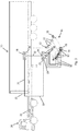
- Fig. 1 shows an embodiment of the commercial vehicle trailer 10 according to the invention, in which each gas valve 13 is associated with a respective switching relay 22.
- Each switching relay 22 has different connections.
- each switching relay 22 comprises an operating current input 36 and an operating current output 37.
- the operating current input 36 is electrically connected to the power supply output 35 of the brake control module 18 or to the operating current output 37 of an upstream switching relay 22.
- the switching relays 22 are thus electrically coupled in a series connection or series connection with the power supply output 35 of the brake control module 18.
- a power connection line 32 is provided, which electrically couples the power supply suction 35 of the brake control module 18 with the operating current input 36 of a first switching relay 22.
- a connecting line is also arranged.
- the switching relays 22 each have a switching current output 38.
- the switching current output 38 is in each case coupled to a switching current line 30 with a gas valve 13.
- each switching relay 22 includes a control signal input 39, which in the embodiment according to Fig. 1 via a respective signal connecting line 34 is signal-connected to the brake control module 38. Via the control signal input 39, the switching relay 22 receives a switching signal, so that an electrical connection between the operating current input 36 and the switching current output 38 is closed or opened.
- the switching relay 22 controls the electrical connection between the power supply suction 35 of the brake control module 18 and the gas valve thirteenth
- the brake control module 18 is connected to the engine controller 21 of the towing vehicle 20 via a power supply line 31. Furthermore, a control signal line 33 is provided which signals the brake control module 18 to the engine control 21 of the towing vehicle 20.
- the power supply line 31 and the control signal line 33 are provided with a detachable terminal connection disposed in the terminal box 23. In other words, an electrical connection and a data or signal connection can be provided in the connection box in order to connect the power supply line 31 and the control signal line 33 to the motor controller 21 in a separable manner.
- the embodiment according to Fig. 2 corresponds in many parts to the embodiment according to Fig. 1 with the difference that the individual switching relays 22 are signal-connected by a control signal line 33 directly to the motor controller 21 of the towing vehicle 20. Only the operating power supply of the switching relay 22 via the brake control module 18.
- the control signal line 33 is in the embodiment according to Fig. 2 preferably also guided over the junction box 23, so that a detachable connection to the engine control 21 of the towing vehicle 20 is made.
- a gas valve control module 19 is provided.
- the gas valve control module 19 is preferably designed as an electronic gas valve control module 19.
- the gas valve control module 19 includes a power supply input 24 which is electrically connected via a power connection line 32 to the power supply output 35 of the brake control module 18.
- the gas valve control module 19 has a data interface 28, which is connected by the control signal line 33 to the engine control 21 of the towing vehicle 20.
- the control signal line 33 is preferably separable and guided via the connection box 23.
- control signal line 33 is separable in the junction box 23, so that the towing vehicle 20 can be completely detached from the commercial vehicle trailer 10.
- the data interface 25 preferably allows bi-directional communication between the engine controller 21 and the gas valve control module 19.
- the gas valve control module 19 further includes a plurality of switching current outputs 38 each connected to a gas valve 13 via a switching power line 30.
- the embodiment according to Fig. 4 differs from the embodiment according to Fig. 3 in that the gas valve control module 19 is signal-connected to the brake control module 18.
- a signal connection line 34 is provided between the gas valve control module 19 and the brake control module 18.
- the signal connection line 34 allows bidirectional data communication between the brake control module 18 and the gas valve control module 19.
- the brake control module 18 is additionally connected via a control signal line 33 to the engine control unit 21 of the towing vehicle, so that data is exchanged between the gas valve control module 19 and the engine control unit 21 via the brake control module 18 can.
- the gas valve control module 19 according to the embodiment according to Fig. 4 a plurality of sensor inputs, to each of which a sensor 17, 18 is connected via a sensor line 27.
- different sensors can be signal-connected to the gas valve control module 19.
- at least one pressure sensor 16 and / or a volume flow sensor 17 is provided.
- a pressure sensor 16 is arranged on the tank module 11, in particular directly connected to at least one gas tank 12. In this way, the pressure within the gas tanks 12 may be monitored by the gas valve control module 19.
- a volume flow sensor 17 may be provided which monitors the volume flow of the gas in the gas line between the tank module 11 and towing vehicle 20.
- the sensor transmits data to the gas valve control module 19.
- the sensor data collected in the gas valve control module 19 can be transferred to the engine control unit 21 and used, for example, to display the status in the driver's cab of the towing vehicle 20. In this way, the gas system in the commercial vehicle trailer 10 can be monitored by the driver.
- the gas valve control module 19 is preferably mounted on the tank module 11.
- the gas valve control module 19 is thus preferably part of the tank module 11.
- Tank module 11 combines, so that a simple retrofitting, initial assembly and maintenance of the commercial vehicle trailer 10 is ensured.
- the tank module 11 is mechanically connected to the vehicle frame of the commercial vehicle trailer 10
- only the electrical connections to the brake control module 18 and the gas connection to the gas line are to be established.
- each gas valve 13 is secured by a separate electrical fuse.
- 30 may be provided in each of the switching power lines, an electrical fuse.
- the switching power lines 30 may also be routed via the junction box 23 so that the electrical fuses, each fuse being associated with a gas valve 13, are located in the junction box 23. In this way, the fuses are easily accessible and can be easily replaced after triggering or transferred to the backup position.
- the interconnection of the gas valves 10 on the commercial vehicle trailer 10 is based in all embodiments on the general idea to use an existing electrical power supply connection to the brake control module 18 as a power source or as a voltage source for the power supply of the gas valves 13.
- the brake control module 18 usually includes a switch identifier, so that the switching state of the gas valves 13 can be detected.
- the brake control module 18 is in practice equipped with a CAN bus interface, so that the data on the switching state of the gas valves 13 can be transmitted to the towing vehicle 20.
- a gas valve control module 19 also data from sensors of the gas system can be tapped and transmitted to the towing vehicle 20.
- the gas valves 13 can be closed during overrun operation of the drive motor and / or opened at a predetermined engine temperature.
- the bidirectional communication via the CAN bus interface also offers the possibility of switching the gas valves 13 and / or the sensor data of the gas system, for example on a screen display represent the towing vehicle 20, so that the driver of the utility vehicle combination information about the state of the gas system in the commercial vehicle trailer 10 are available.
- a gas system on the commercial vehicle trailer 10 can be used not only to supply the drive motor of the tractor 20, but also allow a supply of gas-powered cooling units on the commercial vehicle trailer 10 itself.
Landscapes
- Engineering & Computer Science (AREA)
- Life Sciences & Earth Sciences (AREA)
- Sustainable Development (AREA)
- Sustainable Energy (AREA)
- Chemical & Material Sciences (AREA)
- Combustion & Propulsion (AREA)
- Transportation (AREA)
- Mechanical Engineering (AREA)
- Regulating Braking Force (AREA)
- Filling Or Discharging Of Gas Storage Vessels (AREA)
Priority Applications (1)
| Application Number | Priority Date | Filing Date | Title |
|---|---|---|---|
| PL14185124T PL2878475T3 (pl) | 2013-10-16 | 2014-09-17 | Przyczepy pojazdu użytkowego, zwłaszcza naczepy i zespół pojazdów użytkowych |
Applications Claiming Priority (1)
| Application Number | Priority Date | Filing Date | Title |
|---|---|---|---|
| DE201310111399 DE102013111399A1 (de) | 2013-10-16 | 2013-10-16 | Nutzfahrzeuganhänger, insbesondere Sattelauflieger, mit einem Gastank und Nutzfahrzeuggespann mit einem solchen Nutzfahrzeuganhänger |
Publications (2)
| Publication Number | Publication Date |
|---|---|
| EP2878475A1 EP2878475A1 (de) | 2015-06-03 |
| EP2878475B1 true EP2878475B1 (de) | 2019-11-06 |
Family
ID=51570310
Family Applications (1)
| Application Number | Title | Priority Date | Filing Date |
|---|---|---|---|
| EP14185124.6A Active EP2878475B1 (de) | 2013-10-16 | 2014-09-17 | Nutzfahrzeuganhänger, insbesondere Sattelauflieger, und Nutzfahrzeuggespann |
Country Status (4)
| Country | Link |
|---|---|
| EP (1) | EP2878475B1 (pl) |
| DE (1) | DE102013111399A1 (pl) |
| ES (1) | ES2764137T3 (pl) |
| PL (1) | PL2878475T3 (pl) |
Families Citing this family (1)
| Publication number | Priority date | Publication date | Assignee | Title |
|---|---|---|---|---|
| CN113358374B (zh) * | 2021-08-06 | 2021-11-02 | 中汽研汽车检验中心(宁波)有限公司 | 一种用于商用车的多功能制动试验装置及试验方法 |
Family Cites Families (6)
| Publication number | Priority date | Publication date | Assignee | Title |
|---|---|---|---|---|
| CA2386443C (en) * | 2001-05-17 | 2007-10-23 | Dynetek Industries Ltd. | Replaceable fuel module and method |
| DE10216564B4 (de) * | 2002-04-15 | 2015-12-17 | Wabco Gmbh | Verfahren zum Datenaustausch in einem Fahrzeug, bei dem die einzelnen Fahrzeugteile über einen PLC-Datenbus miteinander verbunden sind |
| US20060244309A1 (en) * | 2005-04-28 | 2006-11-02 | Claussen Stephen P | Vehicle power and communication bus and system |
| DE102005040024B4 (de) * | 2005-08-23 | 2007-10-31 | Cavagna Group S.P.A. | Vorrichtung und Verfahren zur Sicherheitsabsperrung einer Flüssiggas-Anlage für Fahrzeuge und/oder Fahrzeuganhänger im Falle eines Unfalls |
| DE102011056921B4 (de) | 2011-12-22 | 2015-10-22 | Kögel Trailer GmbH & Co. KG | Nutzfahrzeuganhänger für Straßenfahrzeuge, Verfahren zum Betreiben eines motorisierten Nutzfahrzeugs und Straßenfahrzeuggespann |
| DE202012103321U1 (de) * | 2012-08-31 | 2012-09-20 | EES-Autogas Technologiezentrum UG (haftungsbeschränkt) | Vorrichtung zur Anordnung von Gasbehältern in einem Anhänger |
-
2013
- 2013-10-16 DE DE201310111399 patent/DE102013111399A1/de not_active Withdrawn
-
2014
- 2014-09-17 ES ES14185124T patent/ES2764137T3/es active Active
- 2014-09-17 PL PL14185124T patent/PL2878475T3/pl unknown
- 2014-09-17 EP EP14185124.6A patent/EP2878475B1/de active Active
Non-Patent Citations (1)
| Title |
|---|
| None * |
Also Published As
| Publication number | Publication date |
|---|---|
| PL2878475T3 (pl) | 2020-05-18 |
| EP2878475A1 (de) | 2015-06-03 |
| DE102013111399A1 (de) | 2015-04-16 |
| ES2764137T3 (es) | 2020-06-02 |
Similar Documents
| Publication | Publication Date | Title |
|---|---|---|
| EP3668766B2 (de) | Elektropneumatisches anhängerversorgungsmodul zum bereitstellen des anhängerversorgungsdrucks | |
| DE4202729C2 (de) | Steueranlage zum willkürlichen Heben und Senken des Fahrzeugaufbaus von luftgefederten Fahrzeugen | |
| EP3022099B1 (de) | Feststellbremseinrichtung für ein zugfahrzeug einer zugfahrzeug-anhängerkombination mit nachrüstbarer streckbremsventileinrichtung | |
| DE10314643B4 (de) | Druckluftaufbereitungseinrichtung für Kraftfahrzeug-Druckluftanlagen | |
| EP2066536B1 (de) | Wegfahrschultz für anhängefahrzeuge | |
| DE102013020177A1 (de) | Kraftfahrzeug | |
| EP1634729B1 (de) | Steuerung für den Antrieb einer Anhängerkupplung | |
| EP3730363B1 (de) | Hydrauliksystem und fahrzeug | |
| DD297737A5 (de) | Verkabelungssystem fuer fahrzeuge | |
| EP1702802A1 (de) | Steuerungsvorrichtung für Anhänger und Fahrradträger | |
| EP2878475B1 (de) | Nutzfahrzeuganhänger, insbesondere Sattelauflieger, und Nutzfahrzeuggespann | |
| EP2154041B1 (de) | Druckmittelbetätigte Bremsvorrichtung für Kraftfahrzeuge | |
| DE102004056123A1 (de) | Nutzfahrzeug | |
| WO1998004798A2 (de) | Schliessanlage für ein kraftfahrzeug | |
| DE19513004C2 (de) | Steuer- und Überwachungseinrichtung für Bremssysteme von Schienenfahrzeugen | |
| DE19855405B4 (de) | Hydraulische Servolenkung für Kraftfahrzeuge | |
| DE19637484A1 (de) | Zweileitungs-Anhängerbremsanlage | |
| DE102007059438B4 (de) | Verfahren zum Übertragen von Daten zwischen Steuervorrichtungen in einem Fahrzeug | |
| EP3944970A1 (de) | Anhängeranschlussgerät | |
| WO2021009011A1 (de) | Parkbremseinrichtung | |
| DE202011100493U1 (de) | Schaltungsanordnung in einem Zugfahrzeug sowie einem Anhänger | |
| EP3944973A1 (de) | Anhängeranschlussgerät mit stromabnahme-überwachung | |
| EP3944972A1 (de) | Anhängeranschlussgerät mit verbessertem nebelschlussleuchten-betrieb | |
| DE102005060579A1 (de) | Zugfahrzeug | |
| DE19625001C1 (de) | Einrichtung zur Versorgung einer Betriebsleuchte eines Anhängers oder Lasttragmittels bei einem Kraftfahrzeug |
Legal Events
| Date | Code | Title | Description |
|---|---|---|---|
| PUAI | Public reference made under article 153(3) epc to a published international application that has entered the european phase |
Free format text: ORIGINAL CODE: 0009012 |
|
| 17P | Request for examination filed |
Effective date: 20140917 |
|
| AK | Designated contracting states |
Kind code of ref document: A1 Designated state(s): AL AT BE BG CH CY CZ DE DK EE ES FI FR GB GR HR HU IE IS IT LI LT LU LV MC MK MT NL NO PL PT RO RS SE SI SK SM TR |
|
| AX | Request for extension of the european patent |
Extension state: BA ME |
|
| R17P | Request for examination filed (corrected) |
Effective date: 20151202 |
|
| RBV | Designated contracting states (corrected) |
Designated state(s): AL AT BE BG CH CY CZ DE DK EE ES FI FR GB GR HR HU IE IS IT LI LT LU LV MC MK MT NL NO PL PT RO RS SE SI SK SM TR |
|
| GRAP | Despatch of communication of intention to grant a patent |
Free format text: ORIGINAL CODE: EPIDOSNIGR1 |
|
| STAA | Information on the status of an ep patent application or granted ep patent |
Free format text: STATUS: GRANT OF PATENT IS INTENDED |
|
| RAP1 | Party data changed (applicant data changed or rights of an application transferred) |
Owner name: KOEGEL TRAILER GMBH |
|
| RIC1 | Information provided on ipc code assigned before grant |
Ipc: B60K 15/03 20060101AFI20190425BHEP Ipc: B60K 15/07 20060101ALI20190425BHEP |
|
| INTG | Intention to grant announced |
Effective date: 20190515 |
|
| GRAS | Grant fee paid |
Free format text: ORIGINAL CODE: EPIDOSNIGR3 |
|
| GRAA | (expected) grant |
Free format text: ORIGINAL CODE: 0009210 |
|
| STAA | Information on the status of an ep patent application or granted ep patent |
Free format text: STATUS: THE PATENT HAS BEEN GRANTED |
|
| AK | Designated contracting states |
Kind code of ref document: B1 Designated state(s): AL AT BE BG CH CY CZ DE DK EE ES FI FR GB GR HR HU IE IS IT LI LT LU LV MC MK MT NL NO PL PT RO RS SE SI SK SM TR |
|
| REG | Reference to a national code |
Ref country code: GB Ref legal event code: FG4D Free format text: NOT ENGLISH |
|
| REG | Reference to a national code |
Ref country code: CH Ref legal event code: EP Ref country code: AT Ref legal event code: REF Ref document number: 1198274 Country of ref document: AT Kind code of ref document: T Effective date: 20191115 |
|
| REG | Reference to a national code |
Ref country code: DE Ref legal event code: R096 Ref document number: 502014012989 Country of ref document: DE |
|
| REG | Reference to a national code |
Ref country code: IE Ref legal event code: FG4D Free format text: LANGUAGE OF EP DOCUMENT: GERMAN |
|
| REG | Reference to a national code |
Ref country code: NL Ref legal event code: MP Effective date: 20191106 |
|
| REG | Reference to a national code |
Ref country code: LT Ref legal event code: MG4D |
|
| PG25 | Lapsed in a contracting state [announced via postgrant information from national office to epo] |
Ref country code: NO Free format text: LAPSE BECAUSE OF FAILURE TO SUBMIT A TRANSLATION OF THE DESCRIPTION OR TO PAY THE FEE WITHIN THE PRESCRIBED TIME-LIMIT Effective date: 20200206 Ref country code: LT Free format text: LAPSE BECAUSE OF FAILURE TO SUBMIT A TRANSLATION OF THE DESCRIPTION OR TO PAY THE FEE WITHIN THE PRESCRIBED TIME-LIMIT Effective date: 20191106 Ref country code: BG Free format text: LAPSE BECAUSE OF FAILURE TO SUBMIT A TRANSLATION OF THE DESCRIPTION OR TO PAY THE FEE WITHIN THE PRESCRIBED TIME-LIMIT Effective date: 20200206 Ref country code: NL Free format text: LAPSE BECAUSE OF FAILURE TO SUBMIT A TRANSLATION OF THE DESCRIPTION OR TO PAY THE FEE WITHIN THE PRESCRIBED TIME-LIMIT Effective date: 20191106 Ref country code: SE Free format text: LAPSE BECAUSE OF FAILURE TO SUBMIT A TRANSLATION OF THE DESCRIPTION OR TO PAY THE FEE WITHIN THE PRESCRIBED TIME-LIMIT Effective date: 20191106 Ref country code: LV Free format text: LAPSE BECAUSE OF FAILURE TO SUBMIT A TRANSLATION OF THE DESCRIPTION OR TO PAY THE FEE WITHIN THE PRESCRIBED TIME-LIMIT Effective date: 20191106 Ref country code: GR Free format text: LAPSE BECAUSE OF FAILURE TO SUBMIT A TRANSLATION OF THE DESCRIPTION OR TO PAY THE FEE WITHIN THE PRESCRIBED TIME-LIMIT Effective date: 20200207 Ref country code: PT Free format text: LAPSE BECAUSE OF FAILURE TO SUBMIT A TRANSLATION OF THE DESCRIPTION OR TO PAY THE FEE WITHIN THE PRESCRIBED TIME-LIMIT Effective date: 20200306 Ref country code: FI Free format text: LAPSE BECAUSE OF FAILURE TO SUBMIT A TRANSLATION OF THE DESCRIPTION OR TO PAY THE FEE WITHIN THE PRESCRIBED TIME-LIMIT Effective date: 20191106 |
|
| PG25 | Lapsed in a contracting state [announced via postgrant information from national office to epo] |
Ref country code: RS Free format text: LAPSE BECAUSE OF FAILURE TO SUBMIT A TRANSLATION OF THE DESCRIPTION OR TO PAY THE FEE WITHIN THE PRESCRIBED TIME-LIMIT Effective date: 20191106 Ref country code: HR Free format text: LAPSE BECAUSE OF FAILURE TO SUBMIT A TRANSLATION OF THE DESCRIPTION OR TO PAY THE FEE WITHIN THE PRESCRIBED TIME-LIMIT Effective date: 20191106 Ref country code: IS Free format text: LAPSE BECAUSE OF FAILURE TO SUBMIT A TRANSLATION OF THE DESCRIPTION OR TO PAY THE FEE WITHIN THE PRESCRIBED TIME-LIMIT Effective date: 20200306 |
|
| REG | Reference to a national code |
Ref country code: ES Ref legal event code: FG2A Ref document number: 2764137 Country of ref document: ES Kind code of ref document: T3 Effective date: 20200602 |
|
| PG25 | Lapsed in a contracting state [announced via postgrant information from national office to epo] |
Ref country code: AL Free format text: LAPSE BECAUSE OF FAILURE TO SUBMIT A TRANSLATION OF THE DESCRIPTION OR TO PAY THE FEE WITHIN THE PRESCRIBED TIME-LIMIT Effective date: 20191106 |
|
| PG25 | Lapsed in a contracting state [announced via postgrant information from national office to epo] |
Ref country code: DK Free format text: LAPSE BECAUSE OF FAILURE TO SUBMIT A TRANSLATION OF THE DESCRIPTION OR TO PAY THE FEE WITHIN THE PRESCRIBED TIME-LIMIT Effective date: 20191106 Ref country code: EE Free format text: LAPSE BECAUSE OF FAILURE TO SUBMIT A TRANSLATION OF THE DESCRIPTION OR TO PAY THE FEE WITHIN THE PRESCRIBED TIME-LIMIT Effective date: 20191106 Ref country code: RO Free format text: LAPSE BECAUSE OF FAILURE TO SUBMIT A TRANSLATION OF THE DESCRIPTION OR TO PAY THE FEE WITHIN THE PRESCRIBED TIME-LIMIT Effective date: 20191106 |
|
| REG | Reference to a national code |
Ref country code: DE Ref legal event code: R097 Ref document number: 502014012989 Country of ref document: DE |
|
| PG25 | Lapsed in a contracting state [announced via postgrant information from national office to epo] |
Ref country code: SK Free format text: LAPSE BECAUSE OF FAILURE TO SUBMIT A TRANSLATION OF THE DESCRIPTION OR TO PAY THE FEE WITHIN THE PRESCRIBED TIME-LIMIT Effective date: 20191106 Ref country code: SM Free format text: LAPSE BECAUSE OF FAILURE TO SUBMIT A TRANSLATION OF THE DESCRIPTION OR TO PAY THE FEE WITHIN THE PRESCRIBED TIME-LIMIT Effective date: 20191106 |
|
| PLBE | No opposition filed within time limit |
Free format text: ORIGINAL CODE: 0009261 |
|
| STAA | Information on the status of an ep patent application or granted ep patent |
Free format text: STATUS: NO OPPOSITION FILED WITHIN TIME LIMIT |
|
| 26N | No opposition filed |
Effective date: 20200807 |
|
| PG25 | Lapsed in a contracting state [announced via postgrant information from national office to epo] |
Ref country code: SI Free format text: LAPSE BECAUSE OF FAILURE TO SUBMIT A TRANSLATION OF THE DESCRIPTION OR TO PAY THE FEE WITHIN THE PRESCRIBED TIME-LIMIT Effective date: 20191106 |
|
| PG25 | Lapsed in a contracting state [announced via postgrant information from national office to epo] |
Ref country code: IT Free format text: LAPSE BECAUSE OF FAILURE TO SUBMIT A TRANSLATION OF THE DESCRIPTION OR TO PAY THE FEE WITHIN THE PRESCRIBED TIME-LIMIT Effective date: 20191106 |
|
| PG25 | Lapsed in a contracting state [announced via postgrant information from national office to epo] |
Ref country code: MC Free format text: LAPSE BECAUSE OF FAILURE TO SUBMIT A TRANSLATION OF THE DESCRIPTION OR TO PAY THE FEE WITHIN THE PRESCRIBED TIME-LIMIT Effective date: 20191106 |
|
| REG | Reference to a national code |
Ref country code: CH Ref legal event code: PL |
|
| GBPC | Gb: european patent ceased through non-payment of renewal fee |
Effective date: 20200917 |
|
| REG | Reference to a national code |
Ref country code: BE Ref legal event code: MM Effective date: 20200930 |
|
| PG25 | Lapsed in a contracting state [announced via postgrant information from national office to epo] |
Ref country code: LU Free format text: LAPSE BECAUSE OF NON-PAYMENT OF DUE FEES Effective date: 20200917 |
|
| PG25 | Lapsed in a contracting state [announced via postgrant information from national office to epo] |
Ref country code: FR Free format text: LAPSE BECAUSE OF NON-PAYMENT OF DUE FEES Effective date: 20200930 |
|
| PG25 | Lapsed in a contracting state [announced via postgrant information from national office to epo] |
Ref country code: CH Free format text: LAPSE BECAUSE OF NON-PAYMENT OF DUE FEES Effective date: 20200930 Ref country code: BE Free format text: LAPSE BECAUSE OF NON-PAYMENT OF DUE FEES Effective date: 20200930 Ref country code: LI Free format text: LAPSE BECAUSE OF NON-PAYMENT OF DUE FEES Effective date: 20200930 Ref country code: IE Free format text: LAPSE BECAUSE OF NON-PAYMENT OF DUE FEES Effective date: 20200917 Ref country code: GB Free format text: LAPSE BECAUSE OF NON-PAYMENT OF DUE FEES Effective date: 20200917 |
|
| REG | Reference to a national code |
Ref country code: AT Ref legal event code: MM01 Ref document number: 1198274 Country of ref document: AT Kind code of ref document: T Effective date: 20200917 |
|
| PG25 | Lapsed in a contracting state [announced via postgrant information from national office to epo] |
Ref country code: AT Free format text: LAPSE BECAUSE OF NON-PAYMENT OF DUE FEES Effective date: 20200917 |
|
| PG25 | Lapsed in a contracting state [announced via postgrant information from national office to epo] |
Ref country code: TR Free format text: LAPSE BECAUSE OF FAILURE TO SUBMIT A TRANSLATION OF THE DESCRIPTION OR TO PAY THE FEE WITHIN THE PRESCRIBED TIME-LIMIT Effective date: 20191106 Ref country code: MT Free format text: LAPSE BECAUSE OF FAILURE TO SUBMIT A TRANSLATION OF THE DESCRIPTION OR TO PAY THE FEE WITHIN THE PRESCRIBED TIME-LIMIT Effective date: 20191106 Ref country code: CY Free format text: LAPSE BECAUSE OF FAILURE TO SUBMIT A TRANSLATION OF THE DESCRIPTION OR TO PAY THE FEE WITHIN THE PRESCRIBED TIME-LIMIT Effective date: 20191106 |
|
| PG25 | Lapsed in a contracting state [announced via postgrant information from national office to epo] |
Ref country code: MK Free format text: LAPSE BECAUSE OF FAILURE TO SUBMIT A TRANSLATION OF THE DESCRIPTION OR TO PAY THE FEE WITHIN THE PRESCRIBED TIME-LIMIT Effective date: 20191106 |
|
| PGFP | Annual fee paid to national office [announced via postgrant information from national office to epo] |
Ref country code: CZ Payment date: 20240903 Year of fee payment: 11 |
|
| PGFP | Annual fee paid to national office [announced via postgrant information from national office to epo] |
Ref country code: PL Payment date: 20240823 Year of fee payment: 11 |
|
| PGFP | Annual fee paid to national office [announced via postgrant information from national office to epo] |
Ref country code: ES Payment date: 20241017 Year of fee payment: 11 |
|
| PGFP | Annual fee paid to national office [announced via postgrant information from national office to epo] |
Ref country code: DE Payment date: 20250930 Year of fee payment: 12 |