EP2877745B1 - Dosieranlage sowie dosierpumpe hierfür - Google Patents
Dosieranlage sowie dosierpumpe hierfür Download PDFInfo
- Publication number
- EP2877745B1 EP2877745B1 EP13742212.7A EP13742212A EP2877745B1 EP 2877745 B1 EP2877745 B1 EP 2877745B1 EP 13742212 A EP13742212 A EP 13742212A EP 2877745 B1 EP2877745 B1 EP 2877745B1
- Authority
- EP
- European Patent Office
- Prior art keywords
- metering
- pressure
- max
- displacement element
- conveying chamber
- Prior art date
- Legal status (The legal status is an assumption and is not a legal conclusion. Google has not performed a legal analysis and makes no representation as to the accuracy of the status listed.)
- Not-in-force
Links
Images


Classifications
-
- F—MECHANICAL ENGINEERING; LIGHTING; HEATING; WEAPONS; BLASTING
- F04—POSITIVE - DISPLACEMENT MACHINES FOR LIQUIDS; PUMPS FOR LIQUIDS OR ELASTIC FLUIDS
- F04B—POSITIVE-DISPLACEMENT MACHINES FOR LIQUIDS; PUMPS
- F04B13/00—Pumps specially modified to deliver fixed or variable measured quantities
-
- F—MECHANICAL ENGINEERING; LIGHTING; HEATING; WEAPONS; BLASTING
- F04—POSITIVE - DISPLACEMENT MACHINES FOR LIQUIDS; PUMPS FOR LIQUIDS OR ELASTIC FLUIDS
- F04B—POSITIVE-DISPLACEMENT MACHINES FOR LIQUIDS; PUMPS
- F04B15/00—Pumps adapted to handle specific fluids, e.g. by selection of specific materials for pumps or pump parts
- F04B15/02—Pumps adapted to handle specific fluids, e.g. by selection of specific materials for pumps or pump parts the fluids being viscous or non-homogeneous
-
- F—MECHANICAL ENGINEERING; LIGHTING; HEATING; WEAPONS; BLASTING
- F04—POSITIVE - DISPLACEMENT MACHINES FOR LIQUIDS; PUMPS FOR LIQUIDS OR ELASTIC FLUIDS
- F04B—POSITIVE-DISPLACEMENT MACHINES FOR LIQUIDS; PUMPS
- F04B53/00—Component parts, details or accessories not provided for in, or of interest apart from, groups F04B1/00 - F04B23/00 or F04B39/00 - F04B47/00
- F04B53/06—Venting
Definitions
- the present invention relates to a metering system for metering a liquid metering medium with a suction line which is filled with a dosing medium with the liquid pressure p s , and a pressure line which is filled with the metering medium with the liquid pressure p d , wherein the suction line via a metering pump trained dosing is connected to the pressure line. With the help of the dosing pump then dosing can be promoted from the suction line in the pressure line.
- the metering pump has a delivery chamber whose volume can be changed by means of a movable displacement element, for example a membrane, such that in a first position of the displacement element the delivery chamber has a minimum volume V min and in a second position of the displacement element the delivery space has maximum volume V max .
- the delivery chamber is connected via a pressure valve to the pressure line and a suction valve to the suction line, so sucked by an oscillating movement of the displacer in alternation dosing from the suction via the suction valve in the pumping chamber and dosing from the pumping chamber via the pressure valve in the Pressure line can be discharged.
- the displacer element If, therefore, it is no longer possible for the displacer element to apply a sufficiently high pressure to open the pressure valve, the pumped medium is not pumped, that is to say the desired metering can not take place.
- the metering pump has a screwable vent opening to the delivery chamber, which can be opened manually, so that the metering pump does not have to work against the liquid pressure p d , but against the ambient pressure for a short time, so that the gas present in the delivery chamber can escape via the vent opening , Disadvantage of this method, however, is that a manual intervention is necessary.
- Another solution is to equip corresponding vents with an actively controllable valve and to open this valve in periodic sections.
- this method has the disadvantage that the vent opening is also opened when there is no gas in the pumping chamber and therefore a certain leakage current of the pumped medium occurs.
- an additional connection between delivery chamber on the one hand and pressure port on the other hand is provided, which is opened intermittently to allow liquid re-entry from the pressure line into the pumping chamber, which simultaneously gas can escape from the pumping chamber, so that the ratio between compressible gases and incompressible fluids again improved and, ideally, the pressure applied to the pressure port back pressure p d in the delivery chamber can be achieved again.
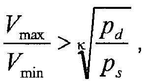
- the exponent k also referred to as the adiabatic exponent, is a physical quantity that describes the ratio of the specific heat capacity of a medium at constant pressure to the specific heat capacity of the medium at constant volume.
- the value k is different for each gas and also temperature dependent. However, it has been found that a value of 1.5 can be used for k to capture all practically relevant use cases.
- the displacement element must work against the back pressure, ie the pressure p d on the pressure line. Since usually the delivery chamber is connected via a check valve to the pressure line, the displacer has to work against the spring of the check valve and optionally - depending on the arrangement of the closing body of the valve - against the weight of the closing body.
- the ratio of the maximum volume V max and the minimum volume V min of the delivery chamber is chosen so large that even if the delivery chamber is completely filled with air, the necessary pressure p d can be achieved.
- the liquid pressure of the metering medium in the suction line p s will correspond to the atmospheric pressure, but also applications are conceivable in which the suction line is already under positive or negative pressure.
- the metering in the pressure line a liquid pressure p d > 7 bar, preferably p d > 10 bar and best p d > 16 bar. Especially at such high liquid pressures is a reliable vent for accurate dosing advantage.
- V Max V min ⁇ 4 preferably V Max V min ⁇ 6 and best V Max V min ⁇ 8th.
- V Max V min ⁇ 4 preferably V Max V min ⁇ 6 and best V Max V min ⁇ 8th.
- the appropriate choice of the ratio between the maximum volume and the minimum volume of the delivery chamber ensures that a dosing, in which the metering pump is used, ensures for most applications that even when completely filled with air delivery chamber, the inherent compressibility of the metering pump large enough is to promote the air from the delivery chamber against the liquid pressure p d of the pressure line.
- a third position of the displacement element in which the delivery chamber has a working volume V A , wherein V min ⁇ V A ⁇ V max , and the metering pump has two modes of operation, wherein in a metering mode the displacer is reciprocated between the first and second positions or between the second and third positions and reciprocated in a bleed mode between the first and second positions ,
- the maximum displacement (V max - V min ) is only achieved during the venting mode, wherein during the normal dosing mode, the displacement is only (V max - V A ) or (V A - V min ).
- a smaller stroke volume and, concomitantly, a smaller stroke of the displacement element can, in particular when the displacement element is designed as a membrane, extend the service life of the displacement element. Therefore, in a preferred embodiment provided that the maximum stroke takes place only in the venting mode, while only a reduced stroke takes place in dosing mode.
- a device which switches the dosing pump at regular intervals for a short time in the venting mode.
- the metering pump could be switched to the venting mode every fiftieth or every two hundredth stroke for one stroke, whereby any gaseous medium possibly located in the delivery chamber is reliably pushed out of the delivery chamber.
- the metering pump may also have a device for detecting a gaseous medium in the delivery chamber, so that a control device may be provided which switches the metering pump in the venting mode when the detection device detects gaseous medium in the head.
- FIG. 1 is a sectional view through a dosing of an embodiment of a metering pump according to the invention shown.
- the dosing head 10 has a displacement element 1, which is connected to a membrane 2. Due to the movement of the displacement element 1, the membrane 2 is moved back and forth, so that the volume of the delivery chamber 3 changes.
- the delivery chamber 3 is connected to a suction port 5 via two series-connected check valves 8, 9, which form the suction valve.
- a suction line of a dosing system can be connected to the suction connection 5, so that dosing medium is sucked out of the suction line into the delivery chamber 3, when the membrane 2 moves together with the displacement element 1 such that the volume of the delivery chamber 3 increases.
- the delivery chamber 3 is also connected to a pressure port 4 via two check valves 6, 7 arranged in series, which together form the pressure valve.
- the pressure connection can be connected to the pressure line of a metering system, so that when the membrane 2 moves together with the displacement element 1 such that the volume of the delivery chamber 3 is reduced, metering via the two check valves 6, 7 and the pressure port 4 in the Pressure line is pressed.
- FIG. 2 is a perspective view of the dosing head 10 can be seen and one recognizes both the pressure port 4 and the suction port. 5
- the delivery chamber 3 consists on the one hand of the space in which the membrane reciprocates and on the other hand from a pressure channel 11 which connects the membrane space with the check valve 7, and a suction channel 12 which connects the membrane space with the check valve 9. Both the pressure channel 11 and the suction channel 12 form part of the delivery chamber volume.
- both the pressure channel 11 and the suction channel 12 are arranged transversely to the direction of movement of the displacement element 1, ie the direction of movement of the displacement element closes with the direction of movement of a closing element of the pressure valve and with the direction of movement a closing element of the suction valve at an angle of about 45 °.
- the ratio V max / V min is about 3. However, this ratio can be chosen to be even greater if the metering pump is to pump against high pressures.
Landscapes
- Engineering & Computer Science (AREA)
- Mechanical Engineering (AREA)
- General Engineering & Computer Science (AREA)
- Reciprocating Pumps (AREA)
- Infusion, Injection, And Reservoir Apparatuses (AREA)
Description
- Die vorliegende Erfindung betrifft eine Dosieranlage zur Dosierung eines flüssigen Dosiermediums mit einer Saugleitung, die mit einem Dosiermedium mit dem Flüssigkeitsdruck ps gefüllt ist, und einer Druckleitung, die mit dem Dosiermedium mit dem Flüssigkeitsdruck pd gefüllt ist, wobei die Saugleitung über ein als Dosierpumpe ausgebildetes Dosierorgan mit der Druckleitung verbunden ist. Mit Hilfe der Dosierpumpe kann dann Dosiermedium aus der Saugleitung in die Druckleitung gefördert werden. Hierzu weist die Dosierpumpe einen Förderraum auf, dessen Volumen mit Hilfe eines bewegbaren Verdrängerelementes, zum Beispiel einer Membran, derart verändert werden kann, dass in einer ersten Position des Verdrängerelementes der Förderraum ein minimales Volumen Vmin und in einer zweiten Position des Verdrängerelementes der Förderraum ein maximales Volumen Vmax aufweist. Dabei ist der Förderraum über ein Druckventil mit der Druckleitung und über ein Saugventil mit der Saugleitung verbunden, so dass durch eine oszillierende Bewegung des Verdrängerelementes im Wechsel Dosiermedium aus der Saugleitung über das Saugventil in den Förderraum gesaugt und Dosiermedium aus dem Förderraum über das Druckventil in die Druckleitung abgegeben werden kann.
- Solche Dosieranlagen und entsprechende Dosierpumpen sind seit langem bekannt.
- In der
EP 1 546 557 B1 ist eine als Membranpumpe ausgebildete Dosierpumpe beschrieben. - Beim Dosieren von Flüssigkeiten, insbesondere von ausgasenden Fördermedien, wie zum Beispiel Natriumhypochlorid (NaClO), können sich Luftblasen in der mit dem Sauganschluss verbundenen Saugleitung bilden und in den Dosierkopf gesaugt werden. Auch ist es möglich, dass sich in der Förderkammer Luftblasen bilden. Dies ist häufig nach längeren Dosierpausen, zum Beispiel nach einem Wochenende, der Fall. Da der Sauganschluss mit einer Saugleitung verbunden ist, die im einfachsten Fall als Schlauch ausgebildet ist und in einem Vorratsbehälter endet, kann es bei einem Austausch des Vorratsbehälters, insbesondere bei laufender Pumpe, vorkommen, dass die Saugleitung kurzzeitig nicht mehr mit dem Fördermedium verbunden ist und Luft ansaugt.
- Befindet sich zu viel Gas im Förderraum einer oszillierenden Förderpumpe, dann kann es zu Störungen des Dosiervorgangs kommen, sofern die eigene Kompressionsfähigkeit der Pumpe aufgrund des eingeschlossenen Gasvolumens nicht ausreicht, um das Druckventil gegen den Flüssigkeitsdruck pd und gegebenenfalls gegen die Rückschlagfeder und das Eigengewicht des Schließkörpers des Druckventils zu öffnen. Mit anderen Worten kann es passieren, dass, wenn der Gasanteil im Förderraum zu hoch wird, trotz der Bewegung des Verdrängerelementes von der zweiten in die erste Position sich der Druck im Förderraum nicht ausreichend erhöht, um das mit dem Druckanschluss verbundene Druckventil zu öffnen. Ursache dafür ist die im Vergleich zu Flüssigkeiten hohe Komprimierbarkeit von Gas.
- Gelingt es daher dem Verdrängerelement nicht mehr, einen genügend hohen Druck zur Öffnung des Druckventils aufzubringen, wird das Fördermedium nicht gepumpt, das heißt die gewünschte Dosierung kann nicht erfolgen.
- Um diesen Fehlerzustand verlassen zu können, ist es notwendig, die Kompressionsfähigkeit auf den am Druckanschluss anliegenden Gegendruck pd wiederherzustellen.
- Hierzu sind verschiedene Lösungsansätze bekannt. Im einfachsten Fall weist die Dosierpumpe eine verschraubbare Entlüftungsöffnung zum Förderraum auf, die manuell geöffnet werden kann, so dass die Dosierpumpe kurzzeitig nicht gegen den Flüssigkeitsdruck pd, sondern gegen den Umgebungsdruck arbeiten muss, so dass das im Förderraum vorhandene Gas über die Entlüftungsöffnung entweichen kann. Nachteil dieses Verfahrens ist jedoch, dass ein manueller Eingriff notwendig ist.
- Eine weitere Lösung besteht darin, entsprechende Entlüftungsöffnungen mit einem aktiv ansteuerbaren Ventil auszustatten und dieses Ventil in periodischen Abschnitten zu öffnen. Dieses Verfahren hat jedoch den Nachteil, dass die Entlüftungsöffnung auch geöffnet wird, wenn sich kein Gas im Förderraum befindet und daher ein gewisser Leckstrom des Fördermediums auftritt.
- Bei der in der
EP 1 546 557 B1 gezeigten Förderpumpe ist hingegen eine zusätzliche Verbindung zwischen Förderraum einerseits und Druckanschluss andererseits vorgesehen, die intermittierend geöffnet wird, um Flüssigkeit den Wiedereintritt von der Druckleitung in den Förderraum zu ermöglichen, wodurch gleichzeitig Gas aus dem Förderraum entweichen kann, so dass sich das Verhältnis zwischen kompressiblen Gasen und inkompressiblen Flüssigkeiten wieder verbessert und im Idealfall der am Druckanschluss anliegende Gegendruck pd in der Förderkammer wieder erreicht werden kann. - Diese Lösung ist jedoch relativ aufwändig, da neben einer zusätzlichen Bypassleitung, ein dieses verschließendes Ventil sowie eine Ansteuervorrichtung zum Ansteuern des Ventils vorgesehen sein muss. Zudem verringert das intermittierende Öffnen des Bypassventils den Wirkungsgrad der Pumpe, da die Öffnung auch dann erfolgt, wenn kein Gas im Förderraum enthalten ist.
- Ausgehend von dem beschriebenen Stand der Technik ist es Aufgabe der vorliegenden Erfindung, eine Dosieranlage sowie eine hierfür angepasste Dosierpumpe zur Verfügung zu stellen, die einen hohen Wirkungsgrad aufweist, keinen Leckstrom zeigt und die einfach aufgebaut ist.
- Hinsichtlich der Dosieranlage wird diese Aufgabe dadurch gelöst, dass

- Der Exponent k wird auch als Adiabatenexponent bezeichnet und ist eine physikalische Größe, die das Verhältnis der spezifischen Wärmekapazität eines Mediums bei konstantem Druck zu der spezifischen Wärmekapazität des Mediums bei konstantem Volumen beschreibt. Der Wert k ist für jedes Gas unterschiedlich und zudem noch termperaturabhängig. Es hat sich jedoch gezeigt, dass für k ein Wert von 1,5 verwendet werden kann, um alle praktisch relevanten Anwendungsfälle zu erfassen. Wie bereits eingangs erwähnt, muss das Verdrängungselement gegen den Gegendruck, d.h. den Druck pd auf der Druckleitung arbeiten. Da in der Regel die Förderkammer über ein Rückschlagventil mit der Druckleitung verbunden ist, muss das Verdrängerelement zusätzlich gegen die Feder des Rückschlagventils und gegebenenfalls - je nach Anordnung des Schließkörpers des Ventils - gegen die Gewichtskraft des Schließkörpers arbeiten.
- Erfindungsgemäß wird daher das Verhältnis aus dem maximalen Volumen Vmax und dem minimalen Volumen Vmin des Förderraums derart groß gewählt, dass selbst dann, wenn der Förderraum vollständig mit Luft gefüllt ist, der notwendige Druck pd erreicht werden kann. In den meisten Fällen wird der Flüssigkeitsdruck des Dosiermediums in der Saugleitung ps dem Atmosphärendruck entsprechen, wobei jedoch auch Anwendungsfälle denkbar sind, in denen die Saugleitung bereits unter Über- oder Unterdruck steht.
- Das Verhältnis zwischen Vmax und Vmin hängt somit von dem zu erwartenden Flüssigkeitsdruck pd in der Druckleitung ab.
- In einer bevorzugten Ausführungsform weist die Dosieranlage in der Druckleitung einen Flüssigkeitsdruck pd > 7 bar, vorzugsweise pd > 10 bar und am besten pd > 16 bar auf. Insbesondere bei derart hohen Flüssigkeitsdrücken ist eine zuverlässige Entlüftung für eine genaue Dosierung von Vorteil.
- Für typische Anwendungsfälle ist in einer bevorzugten Ausführungsform vorgesehen, dass


- Mit den genannten Verhältnissen lassen sich funktionssichere Dosieranlagen für die überwiegende Zahl an Anwendungsfällen erreichen.
- Hinsichtlich der Dosierpumpe zur Verwendung in der beschriebenen erfindungsgemäßen Dosieranlage wird die Aufgabe dadurch gelöst, dass


- Durch die entsprechende Wahl des Verhältnisses zwischen dem maximalen Volumen und dem minimalen Volumen des Förderraums wird sichergestellt, dass eine Dosieranlage, bei der die Dosierpumpe eingesetzt wird, für die meisten Anwendungsfälle gewährleistet, dass selbst bei vollständig mit Luft gefülltem Förderraum die Eigenkompressibilität der Dosierpumpe groß genug ist, um die Luft aus dem Förderraum gegen den Flüssigkeitsdruck pd der Druckleitung zu fördern.
- In einer besonders bevorzugten Ausführungsform der Dosierpumpe ist vorgesehen, dass zwischen der ersten Position und der zweiten Position des Verdrängerelementes eine dritte Position des Verdrängerelementes vorgesehen ist, in welcher der Förderraum ein Arbeitsvolumen VA aufweist, wobei Vmin < VA < Vmax ist, und die Dosierpumpe zwei Betriebsmodi aufweist, wobei in einem Dosiermodus das Verdrängerelement zwischen der ersten und der zweiten Position oder zwischen der zweiten und der dritten Position hin- und herbewegt wird, und in einem Entlüftungsmodus zwischen der ersten und der zweiten Position hin- und herbewegt wird.
- Mit anderen Worten wird das maximale Hubvolumen (Vmax - Vmin) nur während des Entlüftungsmodus erreicht, wobei während des normalen Dosiermodus das Hubvolumen nur (Vmax - VA) bzw. (VA - Vmin) beträgt.
- Ein kleineres Hubvolumen und damit einhergehend eine kleinerer Hub des Verdrängungselementes kann, insbesondere dann, wenn das Verdrängerelement als Membran ausgestaltet ist, die Lebensdauer des Verdrängungselement verlängern. Daher ist in einer bevorzugten Ausführungsform vorgesehen, dass der maximale Hub nur im Entlüftungsmodus stattfindet, während im Dosiermodus lediglich ein reduzierter Hub stattfindet.
- In einer bevorzugten Ausführungsform ist daher eine Einrichtung vorgesehen, welche die Dosierpumpe in regelmäßigen Zeitabständen kurzzeitig in den Entlüftungsmodus schaltet. Beispielsweise könnte die Dosierpumpe jeden fünfzigsten oder jeden zweihundertsten Hub für einen Hub in den Entlüftungsmodus geschaltet werden, wodurch eventuell im Förderraum befindliches gasförmiges Medium, zuverlässig aus dem Förderraum herausgedrückt wird.
- Alternativ dazu kann die Dosierpumpe auch eine Einrichtung zur Erkennung eines gasförmigen Mediums in der Förderkammer aufweisen, so dass eine Steuereinrichtung vorgesehen sein kann, welche die Dosierpumpe in den Entlüftungsmodus schaltet, wenn die Erkennungseinrichtung gasförmiges Medium im Kopf erkennt.
- Weitere Vorteile, Merkmale und Anwendungsmöglichkeiten werden deutlich anhand der folgenden Beschreibung einer bevorzugten Ausführungsform und der zugehörigen Figuren. Es zeigen:
-
Figur 1 einen Querschnitt durch einen Dosierkopf einer erfindungsgemäßen Dosierpumpe und -
Figur 2 eine perspektivische Draufsicht auf die inFigur 1 dargestellte Ausführungsform. - In
Figur 1 ist eine Schnittansicht durch einen Dosierkopf einer Ausführungsform einer erfindungsgemäßen Dosierpumpe gezeigt. Der Dosierkopf 10 weist ein Verdrängerelement 1 auf, das mit einer Membran 2 verbunden ist. Durch die Bewegung des Verdrängerelementes 1 wird die Membran 2 hin- und herbewegt, so dass sich das Volumen des Förderraums 3 verändert. Der Förderraum 3 ist mit einem Sauganschluss 5 über zwei in Reihe geschaltete Rückschlagventile 8, 9, die das Saugventil bilden, verbunden. An den Sauganschluss 5 kann beispielsweise eine Saugleitung einer Dosieranlage angeschlossen werden, so dass Dosiermedium aus der Saugleitung in den Förderraum 3 gesaugt wird, wenn sich die Membran 2 zusammen mit dem Verdrängerelement 1 derart bewegt, dass sich das Volumen des Förderraums 3 vergrößert. - Der Förderraum 3 ist zudem mit einem Druckanschluss 4 über zwei in Reihe angeordnete Rückschlagventile 6, 7, die zusammen das Druckventil bilden, verbunden. Der Druckanschluss kann mit der Druckleitung einer Dosieranlage verbunden werden, so dass, wenn sich die Membran 2 zusammen mit dem Verdrängerelement 1 derart bewegt, dass das Volumen des Förderraums 3 reduziert wird, Dosiermedium über die beiden Rückschlagventile 6, 7 und den Druckanschluss 4 in die Druckleitung gedrückt wird.
- In
Figur 2 ist eine perspektivische Ansicht des Dosierkopfes 10 zu sehen und man erkennt sowohl den Druckanschluss 4 als auch den Sauganschluss 5. - Der Förderraum 3 besteht zum einen aus dem Raum, in dem sich die Membran hin- und herbewegt und zum anderen aus einem Druckkanal 11, welcher den Membranraum mit dem Rückschlagventil 7 verbindet, sowie einem Saugkanal 12, der den Membranraum mit dem Rückschlagventil 9 verbindet. Sowohl der Druckkanal 11 als auch der Saugkanal 12 bilden einen Teil des Förderraumvolumens. Das minimale Volumen Vmin des Förderraums 3, das mit Hilfe der beweglichen Membran 2 eingestellt werden kann, besteht daher mindestens aus dem Volumen des Druckkanals 11 und dem Volumen des Saugkanals 12.
- Um das minimale Volumen Vmin des Förderraums möglichst gering zu wählen, sind hier sowohl der Druckkanal 11 als auch der Saugkanal 12 quer zur Bewegungsrichtung des Verdrängerelementes 1 angeordnet, das heißt die Bewegungsrichtung des Verdrängungselement schließt mit der Bewegungsrichtung eines Schließelementes des Druckventils und mit der Bewegungsrichtung eines Schließelementes des Saugventil einen Winkel von etwa 45° ein.
- Bei der gezeigten Ausführungsform liegt das Verhältnis Vmax/Vmin bei etwa 3. Dieses Verhältnis kann jedoch noch größer gewählt werden, wenn die Dosierpumpe gegen hohe Drücke pumpen soll.
-
- 1
- Verdrängerelement
- 2
- Membran
- 3
- Förderraum
- 4
- Druckanschluss
- 5
- Sauganschluss
- 6, 7
- Rückschlagventile
- 8, 9
- Rückschlagventile
- 10
- Dosierkopf
- 11
- Druckkanal
- 12
- Saugkanal
Claims (8)
- Dosieranlage zur Dosierung eines flüssigen Dosiermediums mit einer Saugleitung, die mit einem Dosiermedium mit dem Flüssigkeitsdruck ps gefüllt ist, und einer Druckleitung, die mit dem Dosiermedium mit dem Flüssigkeitsdruck pd gefüllt ist, wobei die Saugleitung über ein als Dosierpumpe ausgebildetes Dosierorgan mit der Druckleitung verbunden ist, mit der Dosiermedium aus der Saugleitung in die Druckleitung gefördert werden kann, wobei die Dosierpumpe einen Förderraum aufweist, dessen Volumen mit Hilfe eines bewegbaren Verdrängerelementes derart verändert werden kann, dass in einer ersten Position des Verdrängerelementes der Förderraum ein minimales Volumen Vmin und in einer zweiten Position des Verdrängerelementes der Förderraum ein maximales Volumen Vmax aufweist, wobei der Förderraum über ein Druckventil mit der Druckleitung und über ein Saugventil mit der Saugleitung verbunden ist, so dass durch eine oszillierende Bewegung des Verdrängerelementes im Wechsel Dosiermedium aus der Saugleitung über das Saugventil in den Förderraum gesaugt und Dosiermedium aus dem Förderraum über das Druckventil in die Druckleitung abgegeben werden kann, dadurch gekennzeichnet, dass
- Dosieranlage nach Anspruch 1, dadurch gekennzeichnet, dass


- Dosieranlage nach Anspruch 1 oder 2, dadurch gekennzeichnet, dass der Flüssigkeitsdruck pd > 7 bar, vorzugsweise pd > 10 bar und am besten pd > 16 beträgt.
- Dosierpumpe in einer Dosieranlage nach Anspruch 1 oder 2, die einen Förderraum aufweist, dessen Volumen mit Hilfe eines bewegbaren Verdrängerelementes derart verändert werden kann, dass in einer ersten Position des Verdrängerelementes der Förderraum ein minimales Volumen Vmin und in einer zweiten Position des Verdrängerelementes der Förderraum ein maximales Volumen Vmax aufweist, wobei der Förderraum über ein Druckventil mit einem Druckanschluss zur Verbindung mit einer Druckleitung und über ein Saugventil mit einem Sauganschluss zur Verbindung mit einer Saugleitung verbunden ist, dadurch gekennzeichnet, dass


- Dosierpumpe nach Anspruch 4, dadurch gekennzeichnet, dass zwischen der ersten Position und der zweiten Position des Verdrängerelementes eine dritte Position des Verdrängerelementes vorgesehen ist, in welcher der Förderraum ein Arbeitsvolumen VA aufweist, wobei Vmin < VA < Vmax ist, und die Dosierpumpe zwei Betriebsmodi aufweist, wobei in einem Dosiermodus das Verdrängerelement zwischen der zweiten und dritten Position hinund herbewegt wird, und in einem Entlüftungsmodus zwischen der ersten und der zweiten Position hin- und herbewegt wird.
- Dosierpumpe nach Anspruch 4, dadurch gekennzeichnet, dass eine Einrichtung vorgesehen ist, welche die Dosierpumpe in regelmäßigen Zeitabständen kurzzeitig in den Entlüftungsmodus schaltet.
- Dosierpumpe nach Anspruch 4, dadurch gekennzeichnet, dass eine Einrichtung zur Erkennung eines gasförmigen Mediums in der Förderkammer vorgesehen ist und eine Einrichtung vorgesehen ist, welche die Dosierpumpe in den Entlüftungsmodus schaltet, wenn die Erkennungseinrichtung gasförmiges Medium im Kopf erkennt.
- Dosierpumpe nach einem der Ansprüche 4 bis 6, dadurch gekennzeichnet, dass die Bewegungsrichtung des Verdrängungselement mit der Bewegungsrichtung eines Schließelementes des Druckventils und/oder mit der Bewegungsrichtung eines Schließelementes des Saugventil einen Winkel zwischen 15° und 85°, vorzugsweise zwischen 30° und 60° und am besten zwischen 40° und 50° einschließt.
Priority Applications (4)
| Application Number | Priority Date | Filing Date | Title |
|---|---|---|---|
| PL13742212T PL2877745T3 (pl) | 2012-07-27 | 2013-07-25 | Urządzenie dozujące oraz pompa dozująca dla niego |
| HRP20161489TT HRP20161489T1 (hr) | 2012-07-27 | 2013-07-25 | Mjerni sustav i pripadajuća pumpa za mjerenje |
| RS20160967A RS55478B1 (sr) | 2012-07-27 | 2013-07-25 | Uređaj za doziranje kao i odgovarajuća pumpa za doziranje |
| SI201330391A SI2877745T1 (sl) | 2012-07-27 | 2013-07-25 | Dozirni sistem in pa dozirna črpalka zanj |
Applications Claiming Priority (2)
| Application Number | Priority Date | Filing Date | Title |
|---|---|---|---|
| DE102012106848.8A DE102012106848A1 (de) | 2012-07-27 | 2012-07-27 | Dosieranlage sowie Dosierpumpe hierfür |
| PCT/EP2013/065756 WO2014016388A1 (de) | 2012-07-27 | 2013-07-25 | Dosieranlage sowie dosierpumpe hierfür |
Publications (2)
| Publication Number | Publication Date |
|---|---|
| EP2877745A1 EP2877745A1 (de) | 2015-06-03 |
| EP2877745B1 true EP2877745B1 (de) | 2016-10-12 |
Family
ID=48877238
Family Applications (1)
| Application Number | Title | Priority Date | Filing Date |
|---|---|---|---|
| EP13742212.7A Not-in-force EP2877745B1 (de) | 2012-07-27 | 2013-07-25 | Dosieranlage sowie dosierpumpe hierfür |
Country Status (13)
| Country | Link |
|---|---|
| US (1) | US9328722B2 (de) |
| EP (1) | EP2877745B1 (de) |
| JP (1) | JP6339072B2 (de) |
| DE (1) | DE102012106848A1 (de) |
| DK (1) | DK2877745T3 (de) |
| ES (1) | ES2607838T3 (de) |
| HR (1) | HRP20161489T1 (de) |
| HU (1) | HUE030145T2 (de) |
| PL (1) | PL2877745T3 (de) |
| PT (1) | PT2877745T (de) |
| RS (1) | RS55478B1 (de) |
| SI (1) | SI2877745T1 (de) |
| WO (1) | WO2014016388A1 (de) |
Families Citing this family (1)
| Publication number | Priority date | Publication date | Assignee | Title |
|---|---|---|---|---|
| HUE055826T2 (hu) * | 2015-05-21 | 2021-12-28 | Henkel IP & Holding GmbH | Invertáló visszacsapó szelep |
Family Cites Families (11)
| Publication number | Priority date | Publication date | Assignee | Title |
|---|---|---|---|---|
| US3330218A (en) * | 1965-06-11 | 1967-07-11 | James H Bumstead | Metering pump |
| DE3238421A1 (de) * | 1981-10-17 | 1983-05-05 | Barmag Barmer Maschinenfabrik Ag, 5630 Remscheid | Foerdereinrichtung fuer fluessige oder gasfoermige medien |
| SE8305997L (sv) * | 1983-11-01 | 1985-05-02 | Rovac Ab | Doseringsanordning |
| JPH0512669U (ja) * | 1991-07-26 | 1993-02-19 | 日本フイーダー工業株式会社 | 往復動ポンプのストローク調整機構 |
| AU5407896A (en) * | 1995-05-11 | 1996-11-29 | Harry L. Sawatzki | Pump device |
| DE19623537C2 (de) | 1996-06-13 | 2002-03-28 | Bwt Wassertechnik Gmbh | Dosierpumpe und Dosierverfahren für Flüssigkeiten |
| DE10238600A1 (de) * | 2002-08-22 | 2004-03-04 | Fraunhofer-Gesellschaft zur Förderung der angewandten Forschung e.V. | Peristaltische Mikropumpe |
| US7175397B2 (en) | 2002-09-27 | 2007-02-13 | Pulsafeeder, Inc. | Effervescent gas bleeder apparatus |
| US7665974B2 (en) * | 2007-05-02 | 2010-02-23 | Wanner Engineering, Inc. | Diaphragm pump position control with offset valve axis |
| US8128378B2 (en) * | 2007-07-30 | 2012-03-06 | Honeywell International Inc. | Dual mode compensation for variable displacement pump fluid metering system |
| EP2362102B1 (de) | 2010-02-18 | 2012-10-03 | Grundfos Management A/S | Dosierpumpenaggregat |
-
2012
- 2012-07-27 DE DE102012106848.8A patent/DE102012106848A1/de not_active Withdrawn
-
2013
- 2013-07-25 HR HRP20161489TT patent/HRP20161489T1/hr unknown
- 2013-07-25 DK DK13742212.7T patent/DK2877745T3/en active
- 2013-07-25 ES ES13742212.7T patent/ES2607838T3/es active Active
- 2013-07-25 SI SI201330391A patent/SI2877745T1/sl unknown
- 2013-07-25 JP JP2015523554A patent/JP6339072B2/ja active Active
- 2013-07-25 US US14/412,695 patent/US9328722B2/en not_active Expired - Fee Related
- 2013-07-25 PL PL13742212T patent/PL2877745T3/pl unknown
- 2013-07-25 EP EP13742212.7A patent/EP2877745B1/de not_active Not-in-force
- 2013-07-25 RS RS20160967A patent/RS55478B1/sr unknown
- 2013-07-25 PT PT137422127T patent/PT2877745T/pt unknown
- 2013-07-25 HU HUE13742212A patent/HUE030145T2/en unknown
- 2013-07-25 WO PCT/EP2013/065756 patent/WO2014016388A1/de not_active Ceased
Also Published As
| Publication number | Publication date |
|---|---|
| SI2877745T1 (sl) | 2016-12-30 |
| HUE030145T2 (en) | 2017-04-28 |
| EP2877745A1 (de) | 2015-06-03 |
| DE102012106848A1 (de) | 2014-01-30 |
| US20150159639A1 (en) | 2015-06-11 |
| JP2015522761A (ja) | 2015-08-06 |
| WO2014016388A1 (de) | 2014-01-30 |
| ES2607838T3 (es) | 2017-04-04 |
| PL2877745T3 (pl) | 2017-05-31 |
| RS55478B1 (sr) | 2017-04-28 |
| HRP20161489T1 (hr) | 2016-12-16 |
| US9328722B2 (en) | 2016-05-03 |
| DK2877745T3 (en) | 2016-12-12 |
| JP6339072B2 (ja) | 2018-06-06 |
| PT2877745T (pt) | 2016-12-30 |
Similar Documents
| Publication | Publication Date | Title |
|---|---|---|
| EP3781815A1 (de) | Kompressorvorrichtung und kompressionsverfahren | |
| EP2912310A1 (de) | Kolben-membranpumpe | |
| EP3374047B1 (de) | Entgasungsvorrichtung | |
| EP2825774B1 (de) | Verdrängerpumpe mit zwangsentlüftung | |
| DE102009047217A1 (de) | Kolbenplumpe | |
| EP2609332A1 (de) | Membranpumpe mit trägheitsgesteuertem leckergänzungsventil | |
| EP2329147B1 (de) | Pumpenvorrichtung | |
| DE102021002178A1 (de) | Fördereinrichtung | |
| DE102014010108A1 (de) | Hydraulisch angetriebene Membranpumpe | |
| WO2015172981A1 (de) | Hydrauliksystem | |
| EP2609331A2 (de) | Membranpumpe sowie verfahren zum einstellen einer solchen | |
| EP1298379A1 (de) | Vorrichtung zum Dämpfen von Druckpulsationen in einem Fluidsystem, insbesondere in einem Kraftstoffsystem einer Brennkraftmaschine, sowie Kraftstoffsystem | |
| AT517359B1 (de) | Vorrichtung mit intermittierend bereitgestellter flüssiger Kunststoffkomponente | |
| DE102021106765A1 (de) | Membranpumpe zur Förderung eines Fluids | |
| DE102006015845B3 (de) | Verfahren zum Betreiben einer oszillierenden Verdrängerpumpe und oszillierende Verdrängerpumpe | |
| DE3901071C2 (de) | ||
| DE102012106848A1 (de) | Dosieranlage sowie Dosierpumpe hierfür | |
| DE102016119930A1 (de) | Verdrängerpumpe mit einstellbarer Anschlagsfläche | |
| EP3189234B1 (de) | Verdrängerpumpe mit fluidreservoir | |
| DE102013105072A1 (de) | Membranpumpe mit Lagensteuerung | |
| EP1843040B1 (de) | Verfahren zum Betreiben einer oszillierenden Verdrängerpumpe und oszillierende Verdrängerpumpe | |
| WO2007020052A1 (de) | Hydraulischer aktuator, insbesondere für ein fahrwerkstab ilisierungssytem, sowie hydraulikkreislauf mit einem solchen aktuator | |
| DE102010001369B4 (de) | Peristaltisches System, Fluidfördervorrichtung, Pipettiervorrichtung, Manschette und Verfahren zum Betrieb des peristaltischen Systems | |
| DE202008010872U1 (de) | Pumpenvorrichtung | |
| DE102017211269A1 (de) | Pneumatikmotor mit aktiver Hubumschaltung |
Legal Events
| Date | Code | Title | Description |
|---|---|---|---|
| PUAI | Public reference made under article 153(3) epc to a published international application that has entered the european phase |
Free format text: ORIGINAL CODE: 0009012 |
|
| 17P | Request for examination filed |
Effective date: 20150113 |
|
| AK | Designated contracting states |
Kind code of ref document: A1 Designated state(s): AL AT BE BG CH CY CZ DE DK EE ES FI FR GB GR HR HU IE IS IT LI LT LU LV MC MK MT NL NO PL PT RO RS SE SI SK SM TR |
|
| AX | Request for extension of the european patent |
Extension state: BA ME |
|
| DAX | Request for extension of the european patent (deleted) | ||
| GRAP | Despatch of communication of intention to grant a patent |
Free format text: ORIGINAL CODE: EPIDOSNIGR1 |
|
| INTG | Intention to grant announced |
Effective date: 20160617 |
|
| GRAS | Grant fee paid |
Free format text: ORIGINAL CODE: EPIDOSNIGR3 |
|
| GRAA | (expected) grant |
Free format text: ORIGINAL CODE: 0009210 |
|
| AK | Designated contracting states |
Kind code of ref document: B1 Designated state(s): AL AT BE BG CH CY CZ DE DK EE ES FI FR GB GR HR HU IE IS IT LI LT LU LV MC MK MT NL NO PL PT RO RS SE SI SK SM TR |
|
| REG | Reference to a national code |
Ref country code: GB Ref legal event code: FG4D Free format text: NOT ENGLISH |
|
| REG | Reference to a national code |
Ref country code: CH Ref legal event code: EP |
|
| REG | Reference to a national code |
Ref country code: AT Ref legal event code: REF Ref document number: 836779 Country of ref document: AT Kind code of ref document: T Effective date: 20161015 |
|
| REG | Reference to a national code |
Ref country code: IE Ref legal event code: FG4D Free format text: LANGUAGE OF EP DOCUMENT: GERMAN |
|
| RAP2 | Party data changed (patent owner data changed or rights of a patent transferred) |
Owner name: PROMINENT GMBH |
|
| REG | Reference to a national code |
Ref country code: HR Ref legal event code: TUEP Ref document number: P20161489 Country of ref document: HR |
|
| REG | Reference to a national code |
Ref country code: CH Ref legal event code: NV Representative=s name: ISLER AND PEDRAZZINI AG, CH |
|
| REG | Reference to a national code |
Ref country code: DE Ref legal event code: R096 Ref document number: 502013004970 Country of ref document: DE |
|
| REG | Reference to a national code |
Ref country code: RO Ref legal event code: EPE |
|
| REG | Reference to a national code |
Ref country code: DK Ref legal event code: T3 Effective date: 20161207 |
|
| REG | Reference to a national code |
Ref country code: HR Ref legal event code: T1PR Ref document number: P20161489 Country of ref document: HR |
|
| REG | Reference to a national code |
Ref country code: PT Ref legal event code: SC4A Ref document number: 2877745 Country of ref document: PT Date of ref document: 20161230 Kind code of ref document: T Free format text: AVAILABILITY OF NATIONAL TRANSLATION Effective date: 20161219 |
|
| REG | Reference to a national code |
Ref country code: SE Ref legal event code: TRGR |
|
| REG | Reference to a national code |
Ref country code: NL Ref legal event code: FP |
|
| REG | Reference to a national code |
Ref country code: NO Ref legal event code: T2 Effective date: 20161012 |
|
| REG | Reference to a national code |
Ref country code: LT Ref legal event code: MG4D |
|
| REG | Reference to a national code |
Ref country code: EE Ref legal event code: FG4A Ref document number: E013044 Country of ref document: EE Effective date: 20161214 |
|
| PG25 | Lapsed in a contracting state [announced via postgrant information from national office to epo] |
Ref country code: LV Free format text: LAPSE BECAUSE OF FAILURE TO SUBMIT A TRANSLATION OF THE DESCRIPTION OR TO PAY THE FEE WITHIN THE PRESCRIBED TIME-LIMIT Effective date: 20161012 |
|
| PG25 | Lapsed in a contracting state [announced via postgrant information from national office to epo] |
Ref country code: LT Free format text: LAPSE BECAUSE OF FAILURE TO SUBMIT A TRANSLATION OF THE DESCRIPTION OR TO PAY THE FEE WITHIN THE PRESCRIBED TIME-LIMIT Effective date: 20161012 |
|
| REG | Reference to a national code |
Ref country code: HU Ref legal event code: AG4A Ref document number: E030145 Country of ref document: HU |
|
| PG25 | Lapsed in a contracting state [announced via postgrant information from national office to epo] |
Ref country code: IS Free format text: LAPSE BECAUSE OF FAILURE TO SUBMIT A TRANSLATION OF THE DESCRIPTION OR TO PAY THE FEE WITHIN THE PRESCRIBED TIME-LIMIT Effective date: 20170212 |
|
| REG | Reference to a national code |
Ref country code: SK Ref legal event code: T3 Ref document number: E 22921 Country of ref document: SK |
|
| REG | Reference to a national code |
Ref country code: GR Ref legal event code: EP Ref document number: 20160403056 Country of ref document: GR Effective date: 20170410 |
|
| REG | Reference to a national code |
Ref country code: DE Ref legal event code: R097 Ref document number: 502013004970 Country of ref document: DE |
|
| REG | Reference to a national code |
Ref country code: FR Ref legal event code: PLFP Year of fee payment: 5 |
|
| PLBE | No opposition filed within time limit |
Free format text: ORIGINAL CODE: 0009261 |
|
| STAA | Information on the status of an ep patent application or granted ep patent |
Free format text: STATUS: NO OPPOSITION FILED WITHIN TIME LIMIT |
|
| PG25 | Lapsed in a contracting state [announced via postgrant information from national office to epo] |
Ref country code: SM Free format text: LAPSE BECAUSE OF FAILURE TO SUBMIT A TRANSLATION OF THE DESCRIPTION OR TO PAY THE FEE WITHIN THE PRESCRIBED TIME-LIMIT Effective date: 20161012 |
|
| 26N | No opposition filed |
Effective date: 20170713 |
|
| PG25 | Lapsed in a contracting state [announced via postgrant information from national office to epo] |
Ref country code: LU Free format text: LAPSE BECAUSE OF NON-PAYMENT OF DUE FEES Effective date: 20170725 |
|
| REG | Reference to a national code |
Ref country code: FR Ref legal event code: PLFP Year of fee payment: 6 |
|
| PG25 | Lapsed in a contracting state [announced via postgrant information from national office to epo] |
Ref country code: MC Free format text: LAPSE BECAUSE OF FAILURE TO SUBMIT A TRANSLATION OF THE DESCRIPTION OR TO PAY THE FEE WITHIN THE PRESCRIBED TIME-LIMIT Effective date: 20161012 |
|
| REG | Reference to a national code |
Ref country code: HR Ref legal event code: ODRP Ref document number: P20161489 Country of ref document: HR Payment date: 20190709 Year of fee payment: 7 |
|
| PGFP | Annual fee paid to national office [announced via postgrant information from national office to epo] |
Ref country code: PL Payment date: 20190624 Year of fee payment: 7 |
|
| PGFP | Annual fee paid to national office [announced via postgrant information from national office to epo] |
Ref country code: RS Payment date: 20190624 Year of fee payment: 7 Ref country code: MT Payment date: 20190620 Year of fee payment: 7 Ref country code: NL Payment date: 20190719 Year of fee payment: 7 Ref country code: RO Payment date: 20190624 Year of fee payment: 7 |
|
| PGFP | Annual fee paid to national office [announced via postgrant information from national office to epo] |
Ref country code: SK Payment date: 20190625 Year of fee payment: 7 |
|
| PG25 | Lapsed in a contracting state [announced via postgrant information from national office to epo] |
Ref country code: CY Free format text: LAPSE BECAUSE OF FAILURE TO SUBMIT A TRANSLATION OF THE DESCRIPTION OR TO PAY THE FEE WITHIN THE PRESCRIBED TIME-LIMIT Effective date: 20161012 |
|
| PGFP | Annual fee paid to national office [announced via postgrant information from national office to epo] |
Ref country code: NO Payment date: 20190723 Year of fee payment: 7 Ref country code: CZ Payment date: 20190724 Year of fee payment: 7 Ref country code: IE Payment date: 20190724 Year of fee payment: 7 Ref country code: FR Payment date: 20190719 Year of fee payment: 7 Ref country code: SE Payment date: 20190719 Year of fee payment: 7 Ref country code: ES Payment date: 20190823 Year of fee payment: 7 Ref country code: FI Payment date: 20190722 Year of fee payment: 7 Ref country code: PT Payment date: 20190722 Year of fee payment: 7 Ref country code: TR Payment date: 20190717 Year of fee payment: 7 Ref country code: SI Payment date: 20190619 Year of fee payment: 7 Ref country code: EE Payment date: 20190715 Year of fee payment: 7 |
|
| PG25 | Lapsed in a contracting state [announced via postgrant information from national office to epo] |
Ref country code: MK Free format text: LAPSE BECAUSE OF FAILURE TO SUBMIT A TRANSLATION OF THE DESCRIPTION OR TO PAY THE FEE WITHIN THE PRESCRIBED TIME-LIMIT Effective date: 20161012 |
|
| PGFP | Annual fee paid to national office [announced via postgrant information from national office to epo] |
Ref country code: GR Payment date: 20190716 Year of fee payment: 7 Ref country code: HR Payment date: 20190709 Year of fee payment: 7 Ref country code: BE Payment date: 20190718 Year of fee payment: 7 Ref country code: HU Payment date: 20190716 Year of fee payment: 7 Ref country code: BG Payment date: 20190725 Year of fee payment: 7 |
|
| PGFP | Annual fee paid to national office [announced via postgrant information from national office to epo] |
Ref country code: GB Payment date: 20190719 Year of fee payment: 7 Ref country code: AT Payment date: 20190722 Year of fee payment: 7 |
|
| PGFP | Annual fee paid to national office [announced via postgrant information from national office to epo] |
Ref country code: CH Payment date: 20190719 Year of fee payment: 7 |
|
| PG25 | Lapsed in a contracting state [announced via postgrant information from national office to epo] |
Ref country code: AL Free format text: LAPSE BECAUSE OF FAILURE TO SUBMIT A TRANSLATION OF THE DESCRIPTION OR TO PAY THE FEE WITHIN THE PRESCRIBED TIME-LIMIT Effective date: 20161012 |
|
| PGFP | Annual fee paid to national office [announced via postgrant information from national office to epo] |
Ref country code: DK Payment date: 20200723 Year of fee payment: 8 |
|
| PGFP | Annual fee paid to national office [announced via postgrant information from national office to epo] |
Ref country code: IT Payment date: 20200724 Year of fee payment: 8 |
|
| REG | Reference to a national code |
Ref country code: HR Ref legal event code: PBON Ref document number: P20161489 Country of ref document: HR Effective date: 20200725 |
|
| REG | Reference to a national code |
Ref country code: EE Ref legal event code: MM4A Ref document number: E013044 Country of ref document: EE Effective date: 20200731 |
|
| REG | Reference to a national code |
Ref country code: FI Ref legal event code: MAE |
|
| REG | Reference to a national code |
Ref country code: CH Ref legal event code: PL |
|
| REG | Reference to a national code |
Ref country code: NO Ref legal event code: MMEP |
|
| REG | Reference to a national code |
Ref country code: SE Ref legal event code: EUG |
|
| REG | Reference to a national code |
Ref country code: NL Ref legal event code: MM Effective date: 20200801 |
|
| REG | Reference to a national code |
Ref country code: AT Ref legal event code: MM01 Ref document number: 836779 Country of ref document: AT Kind code of ref document: T Effective date: 20200725 |
|
| REG | Reference to a national code |
Ref country code: SK Ref legal event code: MM4A Ref document number: E 22921 Country of ref document: SK Effective date: 20200725 |
|
| GBPC | Gb: european patent ceased through non-payment of renewal fee |
Effective date: 20200725 |
|
| REG | Reference to a national code |
Ref country code: BE Ref legal event code: MM Effective date: 20200731 |
|
| PG25 | Lapsed in a contracting state [announced via postgrant information from national office to epo] |
Ref country code: NL Free format text: LAPSE BECAUSE OF NON-PAYMENT OF DUE FEES Effective date: 20200801 Ref country code: PT Free format text: LAPSE BECAUSE OF NON-PAYMENT OF DUE FEES Effective date: 20210301 Ref country code: NO Free format text: LAPSE BECAUSE OF NON-PAYMENT OF DUE FEES Effective date: 20200731 Ref country code: FR Free format text: LAPSE BECAUSE OF NON-PAYMENT OF DUE FEES Effective date: 20200731 Ref country code: FI Free format text: LAPSE BECAUSE OF NON-PAYMENT OF DUE FEES Effective date: 20200725 Ref country code: RO Free format text: LAPSE BECAUSE OF NON-PAYMENT OF DUE FEES Effective date: 20200725 Ref country code: RS Free format text: LAPSE BECAUSE OF NON-PAYMENT OF DUE FEES Effective date: 20200725 Ref country code: CZ Free format text: LAPSE BECAUSE OF NON-PAYMENT OF DUE FEES Effective date: 20200725 Ref country code: CH Free format text: LAPSE BECAUSE OF NON-PAYMENT OF DUE FEES Effective date: 20200731 Ref country code: EE Free format text: LAPSE BECAUSE OF NON-PAYMENT OF DUE FEES Effective date: 20200731 Ref country code: GR Free format text: LAPSE BECAUSE OF NON-PAYMENT OF DUE FEES Effective date: 20210210 Ref country code: LI Free format text: LAPSE BECAUSE OF NON-PAYMENT OF DUE FEES Effective date: 20200731 Ref country code: GB Free format text: LAPSE BECAUSE OF NON-PAYMENT OF DUE FEES Effective date: 20200725 |
|
| PG25 | Lapsed in a contracting state [announced via postgrant information from national office to epo] |
Ref country code: BG Free format text: LAPSE BECAUSE OF NON-PAYMENT OF DUE FEES Effective date: 20210131 Ref country code: BE Free format text: LAPSE BECAUSE OF NON-PAYMENT OF DUE FEES Effective date: 20200731 Ref country code: AT Free format text: LAPSE BECAUSE OF NON-PAYMENT OF DUE FEES Effective date: 20200725 Ref country code: SI Free format text: LAPSE BECAUSE OF NON-PAYMENT OF DUE FEES Effective date: 20200726 Ref country code: SE Free format text: LAPSE BECAUSE OF NON-PAYMENT OF DUE FEES Effective date: 20200726 |
|
| PG25 | Lapsed in a contracting state [announced via postgrant information from national office to epo] |
Ref country code: SK Free format text: LAPSE BECAUSE OF NON-PAYMENT OF DUE FEES Effective date: 20200725 Ref country code: HR Free format text: LAPSE BECAUSE OF NON-PAYMENT OF DUE FEES Effective date: 20200725 |
|
| PG25 | Lapsed in a contracting state [announced via postgrant information from national office to epo] |
Ref country code: IE Free format text: LAPSE BECAUSE OF NON-PAYMENT OF DUE FEES Effective date: 20200725 |
|
| REG | Reference to a national code |
Ref country code: ES Ref legal event code: FD2A Effective date: 20211230 |
|
| PG25 | Lapsed in a contracting state [announced via postgrant information from national office to epo] |
Ref country code: ES Free format text: LAPSE BECAUSE OF NON-PAYMENT OF DUE FEES Effective date: 20200726 |
|
| REG | Reference to a national code |
Ref country code: DK Ref legal event code: EBP Effective date: 20210731 |
|
| PG25 | Lapsed in a contracting state [announced via postgrant information from national office to epo] |
Ref country code: TR Free format text: LAPSE BECAUSE OF NON-PAYMENT OF DUE FEES Effective date: 20200725 Ref country code: MT Free format text: LAPSE BECAUSE OF NON-PAYMENT OF DUE FEES Effective date: 20200725 |
|
| PG25 | Lapsed in a contracting state [announced via postgrant information from national office to epo] |
Ref country code: IT Free format text: LAPSE BECAUSE OF NON-PAYMENT OF DUE FEES Effective date: 20210725 Ref country code: DK Free format text: LAPSE BECAUSE OF NON-PAYMENT OF DUE FEES Effective date: 20210731 |
|
| PG25 | Lapsed in a contracting state [announced via postgrant information from national office to epo] |
Ref country code: HU Free format text: LAPSE BECAUSE OF NON-PAYMENT OF DUE FEES Effective date: 20200726 |
|
| PG25 | Lapsed in a contracting state [announced via postgrant information from national office to epo] |
Ref country code: HU Free format text: LAPSE BECAUSE OF NON-PAYMENT OF DUE FEES Effective date: 20220726 |
|
| PG25 | Lapsed in a contracting state [announced via postgrant information from national office to epo] |
Ref country code: PL Free format text: LAPSE BECAUSE OF NON-PAYMENT OF DUE FEES Effective date: 20200725 |
|
| PGFP | Annual fee paid to national office [announced via postgrant information from national office to epo] |
Ref country code: DE Payment date: 20230711 Year of fee payment: 11 |
|
| PG25 | Lapsed in a contracting state [announced via postgrant information from national office to epo] |
Ref country code: HU Free format text: LAPSE BECAUSE OF NON-PAYMENT OF DUE FEES Effective date: 20200726 |
|
| REG | Reference to a national code |
Ref country code: DE Ref legal event code: R119 Ref document number: 502013004970 Country of ref document: DE |
|
| PG25 | Lapsed in a contracting state [announced via postgrant information from national office to epo] |
Ref country code: DE Free format text: LAPSE BECAUSE OF NON-PAYMENT OF DUE FEES Effective date: 20250201 |