EP2876707A1 - Device for connecting battery module electrode terminal and terminal - Google Patents
Device for connecting battery module electrode terminal and terminal Download PDFInfo
- Publication number
- EP2876707A1 EP2876707A1 EP13822837.4A EP13822837A EP2876707A1 EP 2876707 A1 EP2876707 A1 EP 2876707A1 EP 13822837 A EP13822837 A EP 13822837A EP 2876707 A1 EP2876707 A1 EP 2876707A1
- Authority
- EP
- European Patent Office
- Prior art keywords
- terminal
- socket
- electrode terminal
- battery module
- coupled
- Prior art date
- Legal status (The legal status is an assumption and is not a legal conclusion. Google has not performed a legal analysis and makes no representation as to the accuracy of the status listed.)
- Granted
Links
- 230000002093 peripheral effect Effects 0.000 claims description 20
- 238000005192 partition Methods 0.000 claims description 14
- 230000008878 coupling Effects 0.000 claims description 9
- 238000010168 coupling process Methods 0.000 claims description 9
- 238000005859 coupling reaction Methods 0.000 claims description 9
- 238000005452 bending Methods 0.000 claims description 3
- 238000000034 method Methods 0.000 description 4
- 238000000926 separation method Methods 0.000 description 3
- WHXSMMKQMYFTQS-UHFFFAOYSA-N Lithium Chemical compound [Li] WHXSMMKQMYFTQS-UHFFFAOYSA-N 0.000 description 2
- 230000003247 decreasing effect Effects 0.000 description 2
- 230000007547 defect Effects 0.000 description 2
- 230000000994 depressogenic effect Effects 0.000 description 2
- 229910052744 lithium Inorganic materials 0.000 description 2
- 238000012423 maintenance Methods 0.000 description 2
- 230000005856 abnormality Effects 0.000 description 1
- OJIJEKBXJYRIBZ-UHFFFAOYSA-N cadmium nickel Chemical compound [Ni].[Cd] OJIJEKBXJYRIBZ-UHFFFAOYSA-N 0.000 description 1
- 230000001413 cellular effect Effects 0.000 description 1
- 238000007599 discharging Methods 0.000 description 1
- 230000000694 effects Effects 0.000 description 1
- 229910052739 hydrogen Inorganic materials 0.000 description 1
- 239000001257 hydrogen Substances 0.000 description 1
- 229910052987 metal hydride Inorganic materials 0.000 description 1
- 238000003466 welding Methods 0.000 description 1
Images


Classifications
-
- H—ELECTRICITY
- H01—ELECTRIC ELEMENTS
- H01R—ELECTRICALLY-CONDUCTIVE CONNECTIONS; STRUCTURAL ASSOCIATIONS OF A PLURALITY OF MUTUALLY-INSULATED ELECTRICAL CONNECTING ELEMENTS; COUPLING DEVICES; CURRENT COLLECTORS
- H01R24/00—Two-part coupling devices, or either of their cooperating parts, characterised by their overall structure
- H01R24/38—Two-part coupling devices, or either of their cooperating parts, characterised by their overall structure having concentrically or coaxially arranged contacts
-
- H—ELECTRICITY
- H01—ELECTRIC ELEMENTS
- H01M—PROCESSES OR MEANS, e.g. BATTERIES, FOR THE DIRECT CONVERSION OF CHEMICAL ENERGY INTO ELECTRICAL ENERGY
- H01M50/00—Constructional details or processes of manufacture of the non-active parts of electrochemical cells other than fuel cells, e.g. hybrid cells
- H01M50/50—Current conducting connections for cells or batteries
- H01M50/543—Terminals
-
- H—ELECTRICITY
- H01—ELECTRIC ELEMENTS
- H01M—PROCESSES OR MEANS, e.g. BATTERIES, FOR THE DIRECT CONVERSION OF CHEMICAL ENERGY INTO ELECTRICAL ENERGY
- H01M50/00—Constructional details or processes of manufacture of the non-active parts of electrochemical cells other than fuel cells, e.g. hybrid cells
- H01M50/50—Current conducting connections for cells or batteries
- H01M50/502—Interconnectors for connecting terminals of adjacent batteries; Interconnectors for connecting cells outside a battery casing
-
- H—ELECTRICITY
- H01—ELECTRIC ELEMENTS
- H01M—PROCESSES OR MEANS, e.g. BATTERIES, FOR THE DIRECT CONVERSION OF CHEMICAL ENERGY INTO ELECTRICAL ENERGY
- H01M50/00—Constructional details or processes of manufacture of the non-active parts of electrochemical cells other than fuel cells, e.g. hybrid cells
- H01M50/50—Current conducting connections for cells or batteries
- H01M50/531—Electrode connections inside a battery casing
-
- H—ELECTRICITY
- H01—ELECTRIC ELEMENTS
- H01R—ELECTRICALLY-CONDUCTIVE CONNECTIONS; STRUCTURAL ASSOCIATIONS OF A PLURALITY OF MUTUALLY-INSULATED ELECTRICAL CONNECTING ELEMENTS; COUPLING DEVICES; CURRENT COLLECTORS
- H01R11/00—Individual connecting elements providing two or more spaced connecting locations for conductive members which are, or may be, thereby interconnected, e.g. end pieces for wires or cables supported by the wire or cable and having means for facilitating electrical connection to some other wire, terminal, or conductive member, blocks of binding posts
- H01R11/11—End pieces or tapping pieces for wires, supported by the wire and for facilitating electrical connection to some other wire, terminal or conductive member
- H01R11/28—End pieces consisting of a ferrule or sleeve
- H01R11/281—End pieces consisting of a ferrule or sleeve for connections to batteries
-
- H—ELECTRICITY
- H01—ELECTRIC ELEMENTS
- H01R—ELECTRICALLY-CONDUCTIVE CONNECTIONS; STRUCTURAL ASSOCIATIONS OF A PLURALITY OF MUTUALLY-INSULATED ELECTRICAL CONNECTING ELEMENTS; COUPLING DEVICES; CURRENT COLLECTORS
- H01R13/00—Details of coupling devices of the kinds covered by groups H01R12/70 or H01R24/00 - H01R33/00
- H01R13/02—Contact members
- H01R13/15—Pins, blades or sockets having separate spring member for producing or increasing contact pressure
- H01R13/187—Pins, blades or sockets having separate spring member for producing or increasing contact pressure with spring member in the socket
-
- H—ELECTRICITY
- H01—ELECTRIC ELEMENTS
- H01R—ELECTRICALLY-CONDUCTIVE CONNECTIONS; STRUCTURAL ASSOCIATIONS OF A PLURALITY OF MUTUALLY-INSULATED ELECTRICAL CONNECTING ELEMENTS; COUPLING DEVICES; CURRENT COLLECTORS
- H01R13/00—Details of coupling devices of the kinds covered by groups H01R12/70 or H01R24/00 - H01R33/00
- H01R13/02—Contact members
- H01R13/20—Pins, blades, or sockets shaped, or provided with separate member, to retain co-operating parts together
-
- H—ELECTRICITY
- H01—ELECTRIC ELEMENTS
- H01R—ELECTRICALLY-CONDUCTIVE CONNECTIONS; STRUCTURAL ASSOCIATIONS OF A PLURALITY OF MUTUALLY-INSULATED ELECTRICAL CONNECTING ELEMENTS; COUPLING DEVICES; CURRENT COLLECTORS
- H01R13/00—Details of coupling devices of the kinds covered by groups H01R12/70 or H01R24/00 - H01R33/00
- H01R13/46—Bases; Cases
- H01R13/50—Bases; Cases formed as an integral body
- H01R13/501—Bases; Cases formed as an integral body comprising an integral hinge or a frangible part
-
- H—ELECTRICITY
- H01—ELECTRIC ELEMENTS
- H01M—PROCESSES OR MEANS, e.g. BATTERIES, FOR THE DIRECT CONVERSION OF CHEMICAL ENERGY INTO ELECTRICAL ENERGY
- H01M50/00—Constructional details or processes of manufacture of the non-active parts of electrochemical cells other than fuel cells, e.g. hybrid cells
- H01M50/50—Current conducting connections for cells or batteries
- H01M50/543—Terminals
- H01M50/547—Terminals characterised by the disposition of the terminals on the cells
- H01M50/55—Terminals characterised by the disposition of the terminals on the cells on the same side of the cell
-
- H—ELECTRICITY
- H01—ELECTRIC ELEMENTS
- H01M—PROCESSES OR MEANS, e.g. BATTERIES, FOR THE DIRECT CONVERSION OF CHEMICAL ENERGY INTO ELECTRICAL ENERGY
- H01M50/00—Constructional details or processes of manufacture of the non-active parts of electrochemical cells other than fuel cells, e.g. hybrid cells
- H01M50/50—Current conducting connections for cells or batteries
- H01M50/543—Terminals
- H01M50/552—Terminals characterised by their shape
- H01M50/553—Terminals adapted for prismatic, pouch or rectangular cells
-
- H—ELECTRICITY
- H01—ELECTRIC ELEMENTS
- H01M—PROCESSES OR MEANS, e.g. BATTERIES, FOR THE DIRECT CONVERSION OF CHEMICAL ENERGY INTO ELECTRICAL ENERGY
- H01M50/00—Constructional details or processes of manufacture of the non-active parts of electrochemical cells other than fuel cells, e.g. hybrid cells
- H01M50/50—Current conducting connections for cells or batteries
- H01M50/543—Terminals
- H01M50/564—Terminals characterised by their manufacturing process
- H01M50/566—Terminals characterised by their manufacturing process by welding, soldering or brazing
-
- Y—GENERAL TAGGING OF NEW TECHNOLOGICAL DEVELOPMENTS; GENERAL TAGGING OF CROSS-SECTIONAL TECHNOLOGIES SPANNING OVER SEVERAL SECTIONS OF THE IPC; TECHNICAL SUBJECTS COVERED BY FORMER USPC CROSS-REFERENCE ART COLLECTIONS [XRACs] AND DIGESTS
- Y02—TECHNOLOGIES OR APPLICATIONS FOR MITIGATION OR ADAPTATION AGAINST CLIMATE CHANGE
- Y02E—REDUCTION OF GREENHOUSE GAS [GHG] EMISSIONS, RELATED TO ENERGY GENERATION, TRANSMISSION OR DISTRIBUTION
- Y02E60/00—Enabling technologies; Technologies with a potential or indirect contribution to GHG emissions mitigation
- Y02E60/10—Energy storage using batteries
Definitions
- the present invention relates to an apparatus for connecting between an electrode terminal of a battery module and a terminal capable of connecting the electrode terminal of the battery module and the terminal coupled to a power cable of an external device to each other.
- an apparatus 1000 for connecting between an electrode terminal of a battery module and a terminal is configured to include a socket terminal 200 having a plurality of elastic contactors 220 extendedly formed at one side of a cylindrical body 210 thereof so as to be spaced apart from each other by a predetermined distance in a circumferential direction and inserted onto and closely adhered to an outer side of the electrode terminal 110 protruding from one side of the battery module 100; and a socket 300 enclosing an outer side of the socket terminal 200 and coupled to the socket terminal 200 so as to be closely adhered thereto and having the terminal 400 coupled to one side thereof, wherein the electrode terminal 110 and the terminal 400 are electrically connected to each other by the socket terminal 200 and the socket 300.
- an inner diameter formed by the bent parts 221 of the plurality of elastic contactors 220 is smaller than the outer diameter of the electrode terminal 110, such that the bent parts 221 of the elastic contactors 220 may be closely adhered and coupled to an outer peripheral surface of the electrode terminal 110 by press-fitting.
Landscapes
- Chemical & Material Sciences (AREA)
- Chemical Kinetics & Catalysis (AREA)
- Electrochemistry (AREA)
- General Chemical & Material Sciences (AREA)
- Connection Of Batteries Or Terminals (AREA)
- Battery Mounting, Suspending (AREA)
Abstract
Description
- The present invention relates to an apparatus for connecting between an electrode terminal of a battery module and a terminal capable of connecting the electrode terminal of the battery module and the terminal coupled to a power cable of an external device to each other.
- Generally, since a secondary battery may be charged and discharged unlike a primary battery, the secondary battery has been applied to various fields such as a digital camera, a cellular phone, a laptop computer, and a hybrid vehicle and has been actively studied. An example of the secondary battery includes a nickel-cadmium battery, a nickel-metal hydride battery, a nickel-hydrogen battery, and a lithium secondary battery. In addition, among these secondary batteries, the lithium secondary battery having a high energy density and a discharging voltage has been mainly studied, and has been commercialized and widely used.
- Further, the secondary battery is configured in a form of a battery module in which a plurality of battery cells are stacked due to the necessity of a high output and a large capacity, wherein the battery module includes an electrode terminal formed so as to protrude outwardly, such that it may be connected to a power cable of an external device.
- Here, the electrode terminal of the battery module has a screw thread formed on an outer peripheral surface thereof, and the power cable of the external device has a terminal coupled thereto. The terminal is inserted onto an outer side of the electrode terminal and is connected to the electrode terminal in a scheme of fixing the terminal using a nut.
- However, in the above-mentioned configuration and scheme, since a tool capable of tightening the nut should be inserted when the battery module is installed in a specific space or a plurality of battery modules are stacked to configure a battery pack, a sufficient space should be secured. In addition, a specific torque should be applied in order to tighten the nut, and disassembling and assembling are difficult at the time of performing a check due to occurrence of abnormality.
- As the related art, European Patent Publication Application No.
0,896,389 entitled "Improved Battery Terminal" has been disclosed. -
- An object of the present invention is to provide an apparatus for connecting between an electrode terminal of a battery module and a terminal capable of simply connecting the electrode terminal protruding outwardly of the battery module and the terminal coupled to a power cable of an external device to each other in a press-fitting scheme.
- In one general aspect, an apparatus for connecting between an electrode terminal of a battery module and a terminal includes: a socket terminal having a plurality of elastic contactors extendedly formed at one side of a cylindrical body thereof so as to be spaced apart from each other by a predetermined distance in a circumferential direction and inserted onto and closely adhered to an outer side of the electrode terminal protruding from one side of the battery module; and a socket enclosing an outer side of the socket terminal and coupled to the socket terminal so as to be closely adhered thereto and having the terminal coupled to one side thereof, wherein the electrode terminal and the terminal are electrically connected to each other by the socket terminal and the socket.
- The socket terminal may have bent parts formed by bending portions of the elastic contactors in a length direction toward the center, and the bent parts of the elastic contactors may be closely adhered to an outer peripheral surface of the electrode terminal.
- The electrode terminal may have a protruding end formed on the outer peripheral surface thereof, and the socket terminal may be inserted onto and coupled to the electrode terminal so that the bent parts of the elastic contactor are caught by the protruding end.
- The socket may have hooking protrusions protruding on an inner peripheral surface thereof, and the socket terminal may have a plurality of coupling holes formed in the body thereof, the hooking protrusions being inserted into and fixed to the coupling holes.
- The socket may have jaws formed on an inner peripheral surface thereof at an opposite side to a side at which the socket is inserted onto the electrode terminal, the jaws having an inner diameter smaller than an outer diameter of the body of the socket terminal.
- The socket terminal may have rotation preventing grooves formed at one side of the body thereof, the rotation preventing grooves having the jaws inserted and seated thereinto.
- The socket may have a vertical plate formed at one side of a cylindrical body thereof enclosing the outer side of the socket terminal and closely adhered to the outer side of the socket terminal, and the terminal may be closely adhered and coupled to the vertical plate.
- The apparatus for connecting between an electrode terminal of a battery module and a terminal may further include a case coupled to the battery module to accommodate the socket, the socket terminal, and the terminal coupled to the electrode terminal therein and closely adhering the socket and the socket terminal to the electrode terminal in a direction in which the socket and the socket terminal are inserted onto the electrode terminal.
- Sliding guides and a hooking jaw may be formed on a partition wall formed in the battery module, and a sliding groove corresponding to the sliding guides and an elastic hook hooked and fixed to the hooking jaw may be formed in the case.
- One side of an elastic plate of the elastic hook may be fixed to the case and the other side thereof may be extended in an opposite direction to a direction in which the case is coupled to the battery module to thereby be longer than the case and the partition wall, and the elastic plate may have a protrusion part formed thereon to thereby be hooked and fixed to the hooking jaw of the partition wall.
- The case may have a fixing protrusion protruding at an inner side thereof, and the terminal may have a cut part formed therein so as to correspond to the fixing protrusion, such that the terminal is closely adhered and fixed by the fixing protrusion.
- In the apparatus for connecting between an electrode terminal of a battery module and a terminal, the electrode terminal of the battery module and the terminal coupled to the power cable may be connected to each other in the press-fitting scheme, such that a separate tool for electrically connecting the electrode terminal and the terminal to each other is not required, and connection is conveniently made.
- In addition, the number of processes for connecting the electrode terminal and the terminal to each other and a time required for these processes may be decreased, and disassembling and assembling are simple, such that maintenance is easy.
- In addition, quality problems such as a problem that a nut becomes loose, a contact defect, and the like, due to insufficiency of a fastening torque that may occur in a nut fastening scheme may be solved.
-
-
FIGS. 1 and2 are an exploded perspective view and an assembled perspective view showing an apparatus for connecting between an electrode terminal of a battery module and a terminal according to an exemplary embodiment of the present invention. -
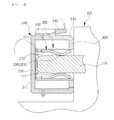
FIG. 3 is a cross-sectional view taken along line A-A' ofFIG. 2 . -
FIG. 4 is a perspective view showing a battery pack including a plurality of battery modules according to an exemplary embodiment of the present invention. -
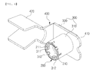
FIGS. 5 and6 are an exploded perspective view and an assembled perspective view showing a coupled structure between a socket and a socket terminal according to an exemplary embodiment of the present invention. -
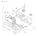
FIGS. 7 and8 are an exploded perspective view and an assembled perspective view showing a coupled structure between a battery module and a case according to an exemplary embodiment of the present invention. -
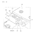
FIG. 9 is a perspective view showing a fixing structure of a case and a terminal according to an exemplary embodiment of the present invention. - Hereinafter, an apparatus for connecting between an electrode terminal of a battery module and a terminal according to an exemplary embodiment of the present invention will be described in detail with reference to the accompanying drawings.
-
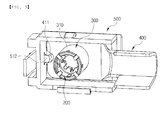
FIGS. 1 and2 are an exploded perspective view and an assembled perspective view showing an apparatus for connecting between an electrode terminal of a battery module and a terminal according to an exemplary embodiment of the present invention. - As shown, an
apparatus 1000 for connecting between an electrode terminal of a battery module and a terminal according to an exemplary embodiment of the present invention is configured to include asocket terminal 200 having a plurality ofelastic contactors 220 extendedly formed at one side of acylindrical body 210 thereof so as to be spaced apart from each other by a predetermined distance in a circumferential direction and inserted onto and closely adhered to an outer side of theelectrode terminal 110 protruding from one side of thebattery module 100; and asocket 300 enclosing an outer side of thesocket terminal 200 and coupled to thesocket terminal 200 so as to be closely adhered thereto and having theterminal 400 coupled to one side thereof, wherein theelectrode terminal 110 and theterminal 400 are electrically connected to each other by thesocket terminal 200 and thesocket 300. - First, the
battery module 100 includes a plurality of battery cells stacked therein and electrically connected to each other, and has theelectrode terminals 110 protruding from one side thereof. Here, theelectrode terminals 110 may include a positive electrode terminal and a negative electrode terminal spaced apart from each other by a predetermined distance and formed in parallel with each other as shown inFIG. 1 , and may be formed at various positions such as a side surface of thebattery module 100 in a length direction, an upper surface of thebattery module 100, or the like. - The
socket terminal 200 has the plurality ofelastic contactors 220 formed at one side of thecylindrical body 210, wherein theelastic contactors 220 are formed so as to be spaced apart from each other by a predetermined distance in the circumferential direction of thebody 210. Here, thecylindrical body 210 has an inner diameter larger than an outer diameter of theelectrode terminal 110, such that thesocket terminal 200 may be easily inserted onto the outer side of theelectrode terminal 110. In addition, theelastic contactors 220 are formed in a form in which they are bent toward a central axis of thecylindrical body 210, such that an inner diameter formed by the plurality ofelastic contactors 220 is smaller than the outer diameter of theelectrode terminal 110. Therefore, when thesocket terminal 200 is inserted onto and coupled to the outer side of theelectrode terminal 110, theelastic contactors 220 of thesocket terminal 200 are closely adhered to theelectrode terminal 110. - The
socket 300 may be inserted onto and be closely adhered and coupled to an outer side of thesocket terminal 200, and be formed in a cylindrical shape so as to enclose the outer side of thesocket terminal 200. In addition, thesocket 300 may have theterminal 400 coupled to one side thereof, wherein theterminal 400 may be fixed and electrically connected to thesocket 300 by welding. - Here, the
terminal 400 has a cable coupledpart 420 formed at one side of ahollow plate 410 of which an inner portion is hollow, wherein thehollow plate 410 may be inserted onto and coupled to an outer side of thesocket 300 and a power cable connected to an external device may be coupled to the cable coupledpart 420. - In a state in which the
socket terminal 200 is inserted and coupled into thesocket 300 as described above, an assembly of thesocket 300 and thesocket terminal 200 is inserted onto and is closely adhered and coupled to the outer side of theelectrode terminal 110, and theterminal 400 is inserted into and welded to the outer side of thesocket 300, such that theelectrode terminal 110 of thebattery module 100 and theterminal 400 may be electrically connected to each other. - Therefore, in the apparatus for connecting between an electrode terminal of a battery module and a terminal according to an exemplary embodiment of the present invention, the electrode terminal of the battery module and the terminal may be connected in a press-fitting scheme by the elastic contactors of the socket terminal inserted and coupled into the socket, such that a separate tool for electrically connecting between the electrode terminal and the terminal is not required, and connection is conveniently made. In addition, the number of processes for connecting the electrode terminal and the terminal to each other and a time required for these processes may be decreased, and disassembling and assembling are simple, such that maintenance is easy. In addition, quality problems such as a problem that a nut becomes loose, a contact defect, and the like, due to insufficiency of a fastening torque that may occur in a nut fastening scheme may be solved.
- In addition, as shown in
FIG. 4 , after a plurality ofbattery modules 100 are stacked and positive electrode terminals and negative electrode terminals ofadjacent battery modules 100 are connected to each other by bus bars, or the like, to form abattery pack 2000, power cables of an external device may be connected to a positive electrode terminal and a negative electrode terminal ofbattery modules 100 disposed at the outermost portion using theapparatus 1000 for connecting between an electrode terminal of a battery module and a terminal according to an exemplary embodiment of the present invention. - In addition, the
socket terminal 200 may havebent parts 221 formed by bending portions of theelastic contactors 220 in the length direction toward the center, and thebent parts 221 of theelastic contactors 220 may be closely adhered to an outer peripheral surface of theelectrode terminal 110. - That is, as shown in
FIG. 3 , one sides of theelastic contactors 220 are coupled to thebody 210 of thesocket terminal 200, portions of theelastic contactors 220 in the length direction extendedly formed are bent toward the central axis of thecylindrical body 210, such that thebent parts 221 are formed, and the other sides (free ends) of theelastic contactors 220, which are an opposite side to a side at which theelastic contactors 220 are coupled to thebody 210, are bent toward an outer side of the central axis of thebody 210. Here, an inner diameter formed by thebent parts 221 of the plurality ofelastic contactors 220 is smaller than the outer diameter of theelectrode terminal 110, such that thebent parts 221 of theelastic contactors 220 may be closely adhered and coupled to an outer peripheral surface of theelectrode terminal 110 by press-fitting. - Therefore, when the
socket terminal 200 is press-fitted onto the outer side of theelectrode terminal 110 in a state in which thesocket terminal 200 is inserted and coupled into thesocket 300, thebody 210 of thesocket terminal 200 and the other sides (free ends) of theelastic contactors 220 of thesocket terminal 200 are closely adhered to an inner peripheral surface of thesocket 300, and thebent parts 221 are closely adhered to the outer peripheral surface of theelectrode terminal 110, such that electrical connection may be stabilized. - Here, the
electrode terminal 110 has a protrudingend 111 formed on the outer peripheral surface thereof, and thesocket terminal 200 may be inserted onto and coupled to theelectrode terminal 110 so that thebent parts 221 of theelastic contactor 220 are caught by the protrudingend 111. - That is, when the
socket terminal 200 coupled into thesocket 300 is inserted onto the outer side of theelectrode terminal 110, thebent parts 221 of theelastic contactors 220 override the protrudingend 111 of theelectrode terminal 110, are spread, and then return to their original state by elasticity. Therefore, since thebent parts 221 of theelastic contactors 220 are caught by the protrudingend 111 formed on the outer peripheral surface of theelectrode terminal 110 after thesocket terminal 200 is coupled to theelectrode terminal 110, thesocket terminal 200 may not be easily withdrawn in an opposite direction to a direction in which it is inserted. - In addition, the
electrode terminal 110 may be generally formed in a cylindrical shape or a prismatic shape, and may have a screw thread formed on the outer peripheral surface thereof. However, it is preferable that theelectrode terminal 110 is smoothly formed so that a contact area between theelectrode terminal 110 and theelastic contactors 220 of thesocket terminal 200 may be increased for the purpose of a smooth flow of a conduction current. In addition, in order to prevent electric conduction and separation, theelectrode terminal 110 may also be formed in a shape in which the outer peripheral surface thereof is depressed so as to correspond to shapes of thebent parts 221 of theelastic contactors 220 of thesocket terminal 200, such that thebent parts 221 are seated onto and are closely adhered and coupled to the depressed portion of theelectrode terminal 110. - In addition, the
socket 300 has hookingprotrusions 311 protruding on the inner peripheral surface thereof, and thesocket terminal 200 has a plurality of coupling holes 211 formed in thebody 210 thereof, wherein the hookingprotrusions 311 may be inserted into and fixed to the coupling holes 211. That is, since movement of thesocket 300 and thesocket terminal 200 in the length direction in which thesocket 300 and thesocket terminal 200 are coupled and inserted is prevented by the hookingprotrusions 311 inserted into the coupling holes 211, theelastic contactors 220 of thesocket terminal 200 may be certainly closely adhered to the outer peripheral surface of theelectrode terminal 110. - In addition, the
socket 300 may havejaws 312 formed on the inner peripheral surface thereof at an opposite side to a side at which it is inserted onto theelectrode terminal 110, wherein thejaws 312 have an inner diameter smaller than an outer diameter of thebody 210 of thesocket terminal 200. Therefore, in a state in which thesocket terminal 200 is inserted and coupled into thesocket 300, thesocket 300 has thejaws 312 formed at the opposite side to the side at which it is inserted onto theelectrode terminal 110, such that thesocket terminal 200 may be press-fitted onto the outer side of theelectrode terminal 110 without being pushed out. Here, as shown inFIGS. 5 and6 , a plurality ofjaws 312 may be formed in a shape in which they protrude from one side of thebody 310 of thesocket 300 toward the central axis, and be formed in a disk shape in which central portions thereof are empty. - In addition, the
socket terminal 200 hasrotation preventing grooves 212 formed at one side of thebody 210 thereof, wherein therotation preventing grooves 212 have thejaws 312 inserted and seated thereinto. That is, thejaws 312 are seated into therotation preventing grooves 212 in a state in which thesocket terminal 200 and thesocket 300 are coupled to each other, such that rotation of thesocket 300 in the circumferential direction is prevented, thereby making it possible to prevent separation between thesocket 300 and thesocket terminal 200. - In addition, the
socket 300 may have avertical plate 320 formed at one side of acylindrical body 310 thereof enclosing the outer side of thesocket terminal 200 and closely adhered to the outer side of thesocket terminal 200, and the terminal 400 may be closely adhered and coupled to thevertical plate 320. That is, when thevertical plate 320 is formed at one side of thecylindrical body 310 of thesocket 300, the terminal 400 may be closely adhered and be then welded to thevertical plate 320, such that coupling and electrical connection may be facilitated. - In addition, the
apparatus 1000 for connecting between an electrode terminal of a battery module and a terminal according to an exemplary embodiment of the present invention may further include acase 500 coupled to thebattery module 100 to accommodate thesocket 300, thesocket terminal 200, and the terminal 400 coupled to theelectrode terminal 110 therein and closely adhering thesocket 300 and thesocket terminal 200 to theelectrode terminal 110 in the direction in which thesocket 300 and thesocket terminal 200 are inserted onto theelectrode terminal 110. That is, thecase 500 may be fixed to thebattery module 100, as shown inFIG. 2 , to protect theelectrode terminal 110, thesocket terminal 200, thesocket 300, and the terminal 400, and acover 530 of thecase 500 may closely adhere thesocket terminal 200 and thesocket 300 to theelectrode terminal 110 in the direction in which thesocket terminal 200 and thesocket 300 are inserted onto theelectrode terminal 110, as shown inFIG. 3 , to prevent thesocket terminal 200 and thesocket 300 from being separated from theelectrode terminal 110. Here, thecase 500 includes thecover 530 hinge-coupled to opened one side of acase body 510 of which both sides are opened and a fixingring 540 hinge-coupled to thecover 530, wherein thecover 530 is closed and the fixingring 540 is hooked and fixed to fixing protrusions formed on thecase body 510. - In addition, sliding
guides 121 and a hookingjaw 122 may be formed on apartition wall 120 formed in thebattery module 100, and a slidinggroove 511 corresponding to the slidingguides 121 and anelastic hook 520 hooked and fixed to the hookingjaw 122 may be formed in thecase 500. That is, as shown inFIGS. 7 and8 , in a state in which the slidingguides 121 are inserted along the slidinggrooves 511 formed at a side surface of thecase body 510, such that one side of thecase body 510 is closely adhered to thebattery modules 100, thecase body 510 is fixed by theelastic hooks 520 and the hookingjaws 122, such that it is not withdrawn backward. Here, thepartition wall 120 of thebattery module 100 may be formed between a pair ofelectrode terminals 110 spaced apart from each other by a predetermined distance, and the slidingguides 121 formed at one side of thepartition wall 120 may be formed in pairs at upper and lower portions so as to be symmetrical to each other and prevent separation of thecase body 510. In addition, thepartition wall 120 may have the hookingjaw 122 formed between the pair of slidingguides 121 so that theelastic hook 520 is hooked thereto. - Further, one side of an
elastic plate 521 of theelastic hook 520 is fixed to the case and the other side thereof is extended in an opposite direction to a direction in which thecase 500 is coupled to thebattery module 100 to thereby be longer than thecase 500 and thepartition wall 120, and theelastic plate 521 has aprotrusion part 522 formed thereon to thereby be hooked and fixed to the hookingjaw 122 of thepartition wall 120. This is to easily disassemble thecase 500, one side of theelastic plate 521 is coupled to a side surface of thecase body 510, that is, a side close to thebattery module 100, and the other side of theelastic plate 521 is lengthily extended to an opposite side so as to be longer than thecase 500 in the length direction, and theprotrusion part 522 is formed on theelastic plate 521. Therefore, in the case in which thecase 500 is coupled to thebattery module 100, when thecase 500 is inserted along the slidingguides 121, thecase 500 is inserted while theelastic plate 521 is pressed, and theprotrusion part 522 is hooked to the hookingjaw 122 in a state in which thecase 500 is closely adhered to thebattery module 100. On the other hand, in the case in which thecase 500 is separated from thebattery module 100, when the other end of theelastic plate 521 that protrudes is pulled toward the case, fixing is released, such that the case may be disassembled along the sliding guides. - In addition, since the
case 500 has a terminal withdrawal part formed so that an opposite side surface thereof in a width direction to a side surface on which thecase body 510 thereof is coupled to thepartition wall 120 of thebattery module 100 is partially opened, the terminal 400 may be coupled to thecase 500 so that the cable coupledpart 420 protrudes outwardly of thecase 500, such that it may be connected to the power cable connected to the external device. - In addition, the
case 500 has a fixingprotrusion 512 protruding at an inner side thereof, and the terminal 400 has acut part 411 formed therein so as to correspond to the fixingprotrusion 512, such that the terminal 400 may be closely adhered and fixed by the fixingprotrusion 512. Referring toFIG. 9 , when thesocket terminal 200, thesocket 300, and the terminal 400 are coupled to each other and are then inserted into the outer side of theelectrode terminal 110 in a state in which thecase 500 is coupled to thebattery module 100, terminal 400 is closely adhered to thebattery module 100 by the fixingprotrusion 512 after thecut part 411 of the terminal 400 is press-fitted while being slid along the fixingprotrusion 512. Therefore, it is possible to prevent the terminal 400, thesocket 300, and thesocket terminal 200 from being separated in an opposite direction to a direction in which the terminal 400, thesocket 300, and thesocket terminal 200 are inserted onto theelectrode terminal 110, by the fixingprotrusion 512 formed at the inner side of thecase 500. Here, the fixingprotrusion 512 may be formed in a '' shape on an inner side wall of the
case 500, and an outer side of a bent portion of the fixingprotrusion 512 may be formed in an inclined shape or a round shape so that thecut part 411 of the terminal 400 is easily slid when being press-fitted. - The present invention is not limited to the above-mentioned exemplary embodiments but may be variously applied, and may be variously modified by those skilled in the art to which the present invention pertains without departing from the gist of the present invention claimed in the claims.
| 1000: | apparatus for connecting between electrode terminal of battery module and terminal | ||
| 100: | battery module | ||
| 110: | electrode terminal | 111: | protruding end |
| 120: | partition wall | 121: | sliding guide |
| 122: | hooking jaw | ||
| 200: | socket terminal | ||
| 210: | body | 211: | coupling hole |
| 212: | rotation preventing groove | ||
| 220: | elastic contactor | 221: | bent part |
| 300: | socket | ||
| 310: | body | 311: | hooking protrusion |
| 312: | jaw | 320: | vertical plate |
| 400: | terminal | ||
| 410: | hollow plate | 411: | cut part |
| 420: | cable coupled part | ||
| 500: | case | ||
| 510: | case body | 511: | sliding groove |
| 512: | fixing protrusion | ||
| 520: | elastic hook | 521: | elastic plate |
| 522: | protrusion part | ||
| 530: | cover | 540: | fixing ring |
| 2000: | battery pack | ||
Claims (11)
- An apparatus for connecting between an electrode terminal of a battery module and a terminal comprising:a socket terminal having a plurality of elastic contactors extendedly formed at one side of a cylindrical body thereof so as to be spaced apart from each other by a predetermined distance in a circumferential direction and inserted onto and closely adhered to an outer side of the electrode terminal protruding from one side of the battery module; anda socket enclosing an outer side of the socket terminal and coupled to the socket terminal so as to be closely adhered thereto and having the terminal coupled to one side thereof,wherein the electrode terminal and the terminal are electrically connected to each other by the socket terminal and the socket.
- The apparatus for connecting between an electrode terminal of a battery module and a terminal of claim 1, wherein the socket terminal has bent parts formed by bending portions of the elastic contactors in a length direction toward the center, and the bent parts of the elastic contactors are closely adhered to an outer peripheral surface of the electrode terminal.
- The apparatus for connecting between an electrode terminal of a battery module and a terminal of claim 2, wherein the electrode terminal has a protruding end formed on the outer peripheral surface thereof, and the socket terminal is inserted onto and coupled to the electrode terminal so that the bent parts of the elastic contactor are caught by the protruding end.
- The apparatus for connecting between an electrode terminal of a battery module and a terminal of claim 1, wherein the socket has hooking protrusions protruding on an inner peripheral surface thereof, and the socket terminal has a plurality of coupling holes formed in the body thereof, the hooking protrusions being inserted into and fixed to the coupling holes.
- The apparatus for connecting between an electrode terminal of a battery module and a terminal of claim 1, wherein the socket has jaws formed on an inner peripheral surface thereof at an opposite side to a side at which the socket is inserted onto the electrode terminal, the jaws having an inner diameter smaller than an outer diameter of the body of the socket terminal.
- The apparatus for connecting between an electrode terminal of a battery module and a terminal of claim 5, wherein the socket terminal has rotation preventing grooves formed at one side of the body thereof, the rotation preventing grooves having the jaws inserted and seated thereinto.
- The apparatus for connecting between an electrode terminal of a battery module and a terminal of claim 1, wherein the socket has a vertical plate formed at one side of a cylindrical body thereof enclosing the outer side of the socket terminal and closely adhered to the outer side of the socket terminal, and the terminal is closely adhered and coupled to the vertical plate.
- The apparatus for connecting between an electrode terminal of a battery module and a terminal of claim 1, further comprising a case coupled to the battery module to accommodate the socket, the socket terminal, and the terminal coupled to the electrode terminal therein and closely adhering the socket and the socket terminal to the electrode terminal in a direction in which the socket and the socket terminal are inserted onto the electrode terminal.
- The apparatus for connecting between an electrode terminal of a battery module and a terminal of claim 8, wherein sliding guides and a hooking jaw are formed on a partition wall formed in the battery module, and a sliding groove corresponding to the sliding guides and an elastic hook hooked and fixed to the hooking jaw are formed in the case.
- The apparatus for connecting between an electrode terminal of a battery module and a terminal of claim 9, wherein one side of an elastic plate of the elastic hook is fixed to the case and the other side thereof is extended in an opposite direction to a direction in which the case is coupled to the battery module to thereby be longer than the case and the partition wall, and the elastic plate has a protrusion part formed thereon to thereby be hooked and fixed to the hooking jaw of the partition wall.
- The apparatus for connecting between an electrode terminal of a battery module and a terminal of claim 8, wherein the case has a fixing protrusion protruding at an inner side thereof, and the terminal has a cut part formed therein so as to correspond to the fixing protrusion, such that the terminal is closely adhered and fixed by the fixing protrusion.
Applications Claiming Priority (2)
| Application Number | Priority Date | Filing Date | Title |
|---|---|---|---|
| KR1020120079769A KR102023916B1 (en) | 2012-07-23 | 2012-07-23 | Connecting apparatus for battery electrode and terminal |
| PCT/KR2013/005276 WO2014017744A1 (en) | 2012-07-23 | 2013-06-14 | Device for connecting battery module electrode terminal and terminal |
Publications (3)
| Publication Number | Publication Date |
|---|---|
| EP2876707A1 true EP2876707A1 (en) | 2015-05-27 |
| EP2876707A4 EP2876707A4 (en) | 2016-08-10 |
| EP2876707B1 EP2876707B1 (en) | 2018-04-18 |
Family
ID=49997517
Family Applications (1)
| Application Number | Title | Priority Date | Filing Date |
|---|---|---|---|
| EP13822837.4A Active EP2876707B1 (en) | 2012-07-23 | 2013-06-14 | Device for connecting terminal with battery module electrode terminal |
Country Status (5)
| Country | Link |
|---|---|
| US (1) | US9515431B2 (en) |
| EP (1) | EP2876707B1 (en) |
| KR (1) | KR102023916B1 (en) |
| CN (1) | CN104488111B (en) |
| WO (1) | WO2014017744A1 (en) |
Cited By (3)
| Publication number | Priority date | Publication date | Assignee | Title |
|---|---|---|---|---|
| FR3062956A1 (en) * | 2017-02-15 | 2018-08-17 | Aptiv Technologies Limited | FEMALE ELECTRICAL CONNECTION ASSEMBLY |
| WO2019120708A1 (en) * | 2017-12-21 | 2019-06-27 | Amphenol-Tuchel Electronics Gmbh | Direct electrical contacting |
| EP3940887A1 (en) * | 2020-07-13 | 2022-01-19 | Abertax Research And Development Ltd. | Auxiliary connector for a battery |
Families Citing this family (20)
| Publication number | Priority date | Publication date | Assignee | Title |
|---|---|---|---|---|
| US11458851B2 (en) | 2014-07-03 | 2022-10-04 | The Noco Company | Jump starting apparatus |
| US11788500B2 (en) | 2016-02-11 | 2023-10-17 | The Noco Company | Battery device for a battery jump starting device |
| US9007015B1 (en) | 2014-07-03 | 2015-04-14 | The Noco Company | Portable vehicle battery jump start apparatus with safety protection |
| JP6475139B2 (en) * | 2015-10-02 | 2019-02-27 | タイコエレクトロニクスジャパン合同会社 | Battery connecting device and battery connecting device assembly |
| KR102065106B1 (en) | 2015-12-18 | 2020-01-10 | 주식회사 엘지화학 | Secondary Battery Pack |
| KR101674991B1 (en) * | 2016-01-15 | 2016-11-11 | 경상북도(농업기술원) | Battery cover for farming machine having improved assembly structure |
| CA3005971C (en) * | 2016-02-11 | 2023-08-29 | The Noco Company | Battery connector device for a battery jump starting device |
| CN107017496A (en) * | 2017-05-26 | 2017-08-04 | 赵沙 | A kind of negative camber for electrical connection system inserts spring terminal |
| CN109390536B (en) * | 2017-08-04 | 2021-04-23 | 莫仕连接器(成都)有限公司 | Battery connection module |
| US12074434B2 (en) | 2017-09-22 | 2024-08-27 | The Noco Company | Portable vehicle battery jump starter with air pump |
| GB2582520B (en) | 2017-12-14 | 2022-08-10 | Noco Co | Portable vehicle battery jump starter with air pump |
| JP6878321B2 (en) * | 2018-01-16 | 2021-05-26 | 株式会社オートネットワーク技術研究所 | Wiring module and power storage module |
| CN108873485A (en) * | 2018-09-10 | 2018-11-23 | 惠州市隆利科技发展有限公司 | A kind of sliceable direct-light-type backlight |
| CN118198662A (en) * | 2018-12-29 | 2024-06-14 | 东莞莫仕连接器有限公司 | Battery connection module |
| KR102366958B1 (en) * | 2020-05-06 | 2022-02-25 | 에너테크인터내셔널 주식회사 | Insulation Cover of Battery Module Terminal |
| KR20210138998A (en) | 2020-05-13 | 2021-11-22 | 삼성에스디아이 주식회사 | Battery pack |
| CN114171956B (en) * | 2021-11-26 | 2023-07-04 | 北京海博思创科技股份有限公司 | Trade electric connector and electric automobile |
| CN116780120A (en) * | 2022-03-08 | 2023-09-19 | 宁德新能源科技有限公司 | Electrochemical device and electronic apparatus |
| CN115207546A (en) * | 2022-08-26 | 2022-10-18 | 安徽五行动力新能源有限公司 | Packaging structure, soft package battery and packaging process thereof |
| KR102572780B1 (en) * | 2023-05-16 | 2023-08-29 | 김영수 | A removable card-type lithium iron phosphate battery mount structure and a mounting method using it |
Family Cites Families (30)
| Publication number | Priority date | Publication date | Assignee | Title |
|---|---|---|---|---|
| US1854489A (en) | 1929-11-20 | 1932-04-19 | Max Corinblatt | Battery jumper |
| US5135403A (en) * | 1991-06-07 | 1992-08-04 | Amp Incorporated | Solderless spring socket for printed circuit board |
| JP2929893B2 (en) * | 1993-03-18 | 1999-08-03 | 住友電装株式会社 | Terminal for connector |
| US5456611A (en) * | 1993-10-28 | 1995-10-10 | The Whitaker Corporation | Mini-UHF snap-on plug |
| US5562506A (en) * | 1995-06-05 | 1996-10-08 | Osram Sylvania Inc. | Radio connector |
| US5672442A (en) * | 1996-09-23 | 1997-09-30 | Yazaki Corporation | Battery terminal and post with rotation inhibiting means |
| US5730628A (en) * | 1996-09-25 | 1998-03-24 | Pacesetter, Inc. | Multi-contact connector for an implantable medical device |
| ES1038047Y (en) | 1997-08-06 | 1998-11-01 | Mecanismos Aux Ind | PERFECTED BATTERY TERMINAL. |
| JPH1169782A (en) * | 1997-08-11 | 1999-03-09 | Seiko Epson Corp | Power-supply circuit, liquid-crystal display device and electronic apparatus |
| US5913694A (en) * | 1997-11-18 | 1999-06-22 | Osram Sylvania Inc. | Connector assembly |
| CA2272458C (en) * | 1998-06-25 | 2008-03-18 | Leslie Laszlo Kerek | Hoodless electrical socket connector |
| JP3224218B2 (en) * | 1999-06-21 | 2001-10-29 | 本田技研工業株式会社 | Battery terminal connection structure |
| KR100345232B1 (en) * | 2000-05-09 | 2002-07-25 | 기아자동차주식회사 | a batery connection structure of vehicle |
| JP3608477B2 (en) * | 2000-06-19 | 2005-01-12 | 住友電装株式会社 | Battery terminal protective cover |
| JP3648437B2 (en) | 2000-08-07 | 2005-05-18 | 矢崎総業株式会社 | Battery terminal |
| JP3645474B2 (en) * | 2000-08-10 | 2005-05-11 | 矢崎総業株式会社 | Battery terminal connection structure |
| JP3972197B2 (en) * | 2002-12-03 | 2007-09-05 | 住友電装株式会社 | Battery connection member |
| US6872099B2 (en) * | 2003-02-18 | 2005-03-29 | Alcoa Fujikura Limited | Stamped battery terminal exhibiting a pivoting clamping mechanism |
| US6966796B2 (en) * | 2003-11-10 | 2005-11-22 | Yazaki Corporation | Connector |
| KR100599754B1 (en) * | 2004-06-29 | 2006-07-12 | 삼성에스디아이 주식회사 | Secondary battery and cap assembly of secondary battery |
| JP2006190565A (en) * | 2005-01-06 | 2006-07-20 | Furukawa Electric Co Ltd:The | Battery terminal |
| US7229327B2 (en) * | 2005-05-25 | 2007-06-12 | Alcoa Fujikura Limited | Canted coil spring power terminal and sequence connection system |
| KR100684846B1 (en) * | 2005-07-29 | 2007-02-20 | 삼성에스디아이 주식회사 | Secondary battery module |
| US7204720B1 (en) * | 2006-01-20 | 2007-04-17 | Singatron Enterprise Co., Ltd. | Power supply connector assembly device |
| US7614921B2 (en) * | 2007-05-04 | 2009-11-10 | Group Dekko, Inc. | Battery post electrical terminal for electrically coupling an electrical conductor with the battery post of a battery |
| KR100971367B1 (en) | 2007-05-31 | 2010-07-20 | 주식회사 엘지화학 | Electrical Connecting Member of Assembling Type and Secondary Battery Pack Containing the Same |
| DE102009038091B3 (en) * | 2009-08-19 | 2010-11-04 | Amphenol-Tuchel Electronics Gmbh | High current contact bushing i.e. radsok-contact bush, has contact arms attached peripherally at gutters, and hyperbolic contact lamella lattice making connection with inner sleeve by welding spots within region of bending section of arms |
| WO2011077190A1 (en) * | 2009-12-23 | 2011-06-30 | Fci Automotive Holding | Power contact |
| FR2970605B1 (en) * | 2011-01-14 | 2013-02-08 | Radiall Sa | SLEEVE FOR ELECTRICAL CONNECTOR AND METHOD FOR ASSEMBLING SAME. |
| KR102024002B1 (en) | 2012-07-05 | 2019-09-23 | 에스케이이노베이션 주식회사 | Battery pack |
-
2012
- 2012-07-23 KR KR1020120079769A patent/KR102023916B1/en active IP Right Grant
-
2013
- 2013-06-14 CN CN201380038865.0A patent/CN104488111B/en active Active
- 2013-06-14 EP EP13822837.4A patent/EP2876707B1/en active Active
- 2013-06-14 WO PCT/KR2013/005276 patent/WO2014017744A1/en active Application Filing
- 2013-06-14 US US14/416,136 patent/US9515431B2/en active Active
Cited By (3)
| Publication number | Priority date | Publication date | Assignee | Title |
|---|---|---|---|---|
| FR3062956A1 (en) * | 2017-02-15 | 2018-08-17 | Aptiv Technologies Limited | FEMALE ELECTRICAL CONNECTION ASSEMBLY |
| WO2019120708A1 (en) * | 2017-12-21 | 2019-06-27 | Amphenol-Tuchel Electronics Gmbh | Direct electrical contacting |
| EP3940887A1 (en) * | 2020-07-13 | 2022-01-19 | Abertax Research And Development Ltd. | Auxiliary connector for a battery |
Also Published As
| Publication number | Publication date |
|---|---|
| EP2876707A4 (en) | 2016-08-10 |
| KR20140013241A (en) | 2014-02-05 |
| WO2014017744A1 (en) | 2014-01-30 |
| CN104488111A (en) | 2015-04-01 |
| KR102023916B1 (en) | 2019-09-23 |
| EP2876707B1 (en) | 2018-04-18 |
| US9515431B2 (en) | 2016-12-06 |
| CN104488111B (en) | 2017-03-08 |
| US20150222060A1 (en) | 2015-08-06 |
Similar Documents
| Publication | Publication Date | Title |
|---|---|---|
| EP2876707B1 (en) | Device for connecting terminal with battery module electrode terminal | |
| EP2871695B1 (en) | Battery pack | |
| US9472793B2 (en) | Battery pack | |
| US9553295B2 (en) | Battery pack | |
| US10243193B2 (en) | Battery pack | |
| US10608216B2 (en) | Battery module and battery pack including same | |
| EP3389114B1 (en) | Battery module, and battery pack comprising same | |
| KR20170054878A (en) | Battery module and battery pack including the same | |
| EP3154108B1 (en) | Battery module and battery pack including same | |
| KR102069152B1 (en) | Electrode tab connecting apparatus and battery module having the same | |
| EP2804235B1 (en) | Secondary battery | |
| US11205817B2 (en) | Battery pack | |
| KR102117076B1 (en) | Battery Module Assembly | |
| KR20170083311A (en) | Battery pack | |
| KR20160012021A (en) | Battery module comprising a unit battery module and battery pack comprisng the same and Method of manufacturing the battery module | |
| KR20170054881A (en) | Battery module and battery pack including the same | |
| KR101335183B1 (en) | Pole rod assembly for battery using push nut | |
| KR20130044719A (en) | Battery pack |
Legal Events
| Date | Code | Title | Description |
|---|---|---|---|
| PUAI | Public reference made under article 153(3) epc to a published international application that has entered the european phase |
Free format text: ORIGINAL CODE: 0009012 |
|
| 17P | Request for examination filed |
Effective date: 20150219 |
|
| AK | Designated contracting states |
Kind code of ref document: A1 Designated state(s): AL AT BE BG CH CY CZ DE DK EE ES FI FR GB GR HR HU IE IS IT LI LT LU LV MC MK MT NL NO PL PT RO RS SE SI SK SM TR |
|
| AX | Request for extension of the european patent |
Extension state: BA ME |
|
| DAX | Request for extension of the european patent (deleted) | ||
| RIC1 | Information provided on ipc code assigned before grant |
Ipc: H01M 2/20 20060101ALI20160218BHEP Ipc: H01M 2/26 20060101AFI20160218BHEP Ipc: H01R 11/28 20060101ALI20160218BHEP Ipc: H01M 2/30 20060101ALI20160218BHEP |
|
| RA4 | Supplementary search report drawn up and despatched (corrected) |
Effective date: 20160711 |
|
| RIC1 | Information provided on ipc code assigned before grant |
Ipc: H01R 13/50 20060101ALN20160705BHEP Ipc: H01R 13/187 20060101ALI20160705BHEP Ipc: H01R 13/20 20060101ALN20160705BHEP Ipc: H01R 11/28 20060101ALI20160705BHEP Ipc: H01M 2/30 20060101AFI20160705BHEP Ipc: H01M 2/20 20060101ALI20160705BHEP |
|
| REG | Reference to a national code |
Ref country code: DE Ref legal event code: R079 Ref document number: 602013036203 Country of ref document: DE Free format text: PREVIOUS MAIN CLASS: H01M0002260000 Ipc: H01M0002300000 |
|
| GRAP | Despatch of communication of intention to grant a patent |
Free format text: ORIGINAL CODE: EPIDOSNIGR1 |
|
| RIC1 | Information provided on ipc code assigned before grant |
Ipc: H01R 11/28 20060101ALI20171025BHEP Ipc: H01M 2/30 20060101AFI20171025BHEP Ipc: H01R 13/20 20060101ALN20171025BHEP Ipc: H01R 13/50 20060101ALN20171025BHEP Ipc: H01M 2/20 20060101ALI20171025BHEP Ipc: H01R 13/187 20060101ALI20171025BHEP |
|
| INTG | Intention to grant announced |
Effective date: 20171113 |
|
| GRAS | Grant fee paid |
Free format text: ORIGINAL CODE: EPIDOSNIGR3 |
|
| GRAA | (expected) grant |
Free format text: ORIGINAL CODE: 0009210 |
|
| AK | Designated contracting states |
Kind code of ref document: B1 Designated state(s): AL AT BE BG CH CY CZ DE DK EE ES FI FR GB GR HR HU IE IS IT LI LT LU LV MC MK MT NL NO PL PT RO RS SE SI SK SM TR |
|
| REG | Reference to a national code |
Ref country code: GB Ref legal event code: FG4D |
|
| REG | Reference to a national code |
Ref country code: CH Ref legal event code: EP |
|
| REG | Reference to a national code |
Ref country code: AT Ref legal event code: REF Ref document number: 991365 Country of ref document: AT Kind code of ref document: T Effective date: 20180515 |
|
| REG | Reference to a national code |
Ref country code: IE Ref legal event code: FG4D |
|
| REG | Reference to a national code |
Ref country code: DE Ref legal event code: R096 Ref document number: 602013036203 Country of ref document: DE |
|
| REG | Reference to a national code |
Ref country code: NL Ref legal event code: MP Effective date: 20180418 |
|
| REG | Reference to a national code |
Ref country code: LT Ref legal event code: MG4D |
|
| PG25 | Lapsed in a contracting state [announced via postgrant information from national office to epo] |
Ref country code: NL Free format text: LAPSE BECAUSE OF FAILURE TO SUBMIT A TRANSLATION OF THE DESCRIPTION OR TO PAY THE FEE WITHIN THE PRESCRIBED TIME-LIMIT Effective date: 20180418 |
|
| PG25 | Lapsed in a contracting state [announced via postgrant information from national office to epo] |
Ref country code: AL Free format text: LAPSE BECAUSE OF FAILURE TO SUBMIT A TRANSLATION OF THE DESCRIPTION OR TO PAY THE FEE WITHIN THE PRESCRIBED TIME-LIMIT Effective date: 20180418 Ref country code: BG Free format text: LAPSE BECAUSE OF FAILURE TO SUBMIT A TRANSLATION OF THE DESCRIPTION OR TO PAY THE FEE WITHIN THE PRESCRIBED TIME-LIMIT Effective date: 20180718 Ref country code: PL Free format text: LAPSE BECAUSE OF FAILURE TO SUBMIT A TRANSLATION OF THE DESCRIPTION OR TO PAY THE FEE WITHIN THE PRESCRIBED TIME-LIMIT Effective date: 20180418 Ref country code: FI Free format text: LAPSE BECAUSE OF FAILURE TO SUBMIT A TRANSLATION OF THE DESCRIPTION OR TO PAY THE FEE WITHIN THE PRESCRIBED TIME-LIMIT Effective date: 20180418 Ref country code: LT Free format text: LAPSE BECAUSE OF FAILURE TO SUBMIT A TRANSLATION OF THE DESCRIPTION OR TO PAY THE FEE WITHIN THE PRESCRIBED TIME-LIMIT Effective date: 20180418 Ref country code: SE Free format text: LAPSE BECAUSE OF FAILURE TO SUBMIT A TRANSLATION OF THE DESCRIPTION OR TO PAY THE FEE WITHIN THE PRESCRIBED TIME-LIMIT Effective date: 20180418 Ref country code: NO Free format text: LAPSE BECAUSE OF FAILURE TO SUBMIT A TRANSLATION OF THE DESCRIPTION OR TO PAY THE FEE WITHIN THE PRESCRIBED TIME-LIMIT Effective date: 20180718 Ref country code: ES Free format text: LAPSE BECAUSE OF FAILURE TO SUBMIT A TRANSLATION OF THE DESCRIPTION OR TO PAY THE FEE WITHIN THE PRESCRIBED TIME-LIMIT Effective date: 20180418 |
|
| PG25 | Lapsed in a contracting state [announced via postgrant information from national office to epo] |
Ref country code: GR Free format text: LAPSE BECAUSE OF FAILURE TO SUBMIT A TRANSLATION OF THE DESCRIPTION OR TO PAY THE FEE WITHIN THE PRESCRIBED TIME-LIMIT Effective date: 20180719 Ref country code: RS Free format text: LAPSE BECAUSE OF FAILURE TO SUBMIT A TRANSLATION OF THE DESCRIPTION OR TO PAY THE FEE WITHIN THE PRESCRIBED TIME-LIMIT Effective date: 20180418 Ref country code: HR Free format text: LAPSE BECAUSE OF FAILURE TO SUBMIT A TRANSLATION OF THE DESCRIPTION OR TO PAY THE FEE WITHIN THE PRESCRIBED TIME-LIMIT Effective date: 20180418 Ref country code: LV Free format text: LAPSE BECAUSE OF FAILURE TO SUBMIT A TRANSLATION OF THE DESCRIPTION OR TO PAY THE FEE WITHIN THE PRESCRIBED TIME-LIMIT Effective date: 20180418 |
|
| REG | Reference to a national code |
Ref country code: AT Ref legal event code: MK05 Ref document number: 991365 Country of ref document: AT Kind code of ref document: T Effective date: 20180418 |
|
| PG25 | Lapsed in a contracting state [announced via postgrant information from national office to epo] |
Ref country code: PT Free format text: LAPSE BECAUSE OF FAILURE TO SUBMIT A TRANSLATION OF THE DESCRIPTION OR TO PAY THE FEE WITHIN THE PRESCRIBED TIME-LIMIT Effective date: 20180820 |
|
| REG | Reference to a national code |
Ref country code: DE Ref legal event code: R097 Ref document number: 602013036203 Country of ref document: DE |
|
| PG25 | Lapsed in a contracting state [announced via postgrant information from national office to epo] |
Ref country code: AT Free format text: LAPSE BECAUSE OF FAILURE TO SUBMIT A TRANSLATION OF THE DESCRIPTION OR TO PAY THE FEE WITHIN THE PRESCRIBED TIME-LIMIT Effective date: 20180418 Ref country code: EE Free format text: LAPSE BECAUSE OF FAILURE TO SUBMIT A TRANSLATION OF THE DESCRIPTION OR TO PAY THE FEE WITHIN THE PRESCRIBED TIME-LIMIT Effective date: 20180418 Ref country code: DK Free format text: LAPSE BECAUSE OF FAILURE TO SUBMIT A TRANSLATION OF THE DESCRIPTION OR TO PAY THE FEE WITHIN THE PRESCRIBED TIME-LIMIT Effective date: 20180418 Ref country code: RO Free format text: LAPSE BECAUSE OF FAILURE TO SUBMIT A TRANSLATION OF THE DESCRIPTION OR TO PAY THE FEE WITHIN THE PRESCRIBED TIME-LIMIT Effective date: 20180418 Ref country code: CZ Free format text: LAPSE BECAUSE OF FAILURE TO SUBMIT A TRANSLATION OF THE DESCRIPTION OR TO PAY THE FEE WITHIN THE PRESCRIBED TIME-LIMIT Effective date: 20180418 Ref country code: SK Free format text: LAPSE BECAUSE OF FAILURE TO SUBMIT A TRANSLATION OF THE DESCRIPTION OR TO PAY THE FEE WITHIN THE PRESCRIBED TIME-LIMIT Effective date: 20180418 |
|
| REG | Reference to a national code |
Ref country code: CH Ref legal event code: PL |
|
| PLBE | No opposition filed within time limit |
Free format text: ORIGINAL CODE: 0009261 |
|
| STAA | Information on the status of an ep patent application or granted ep patent |
Free format text: STATUS: NO OPPOSITION FILED WITHIN TIME LIMIT |
|
| PG25 | Lapsed in a contracting state [announced via postgrant information from national office to epo] |
Ref country code: SM Free format text: LAPSE BECAUSE OF FAILURE TO SUBMIT A TRANSLATION OF THE DESCRIPTION OR TO PAY THE FEE WITHIN THE PRESCRIBED TIME-LIMIT Effective date: 20180418 Ref country code: IT Free format text: LAPSE BECAUSE OF FAILURE TO SUBMIT A TRANSLATION OF THE DESCRIPTION OR TO PAY THE FEE WITHIN THE PRESCRIBED TIME-LIMIT Effective date: 20180418 |
|
| REG | Reference to a national code |
Ref country code: BE Ref legal event code: MM Effective date: 20180630 |
|
| REG | Reference to a national code |
Ref country code: IE Ref legal event code: MM4A |
|
| 26N | No opposition filed |
Effective date: 20190121 |
|
| GBPC | Gb: european patent ceased through non-payment of renewal fee |
Effective date: 20180718 |
|
| PG25 | Lapsed in a contracting state [announced via postgrant information from national office to epo] |
Ref country code: LU Free format text: LAPSE BECAUSE OF NON-PAYMENT OF DUE FEES Effective date: 20180614 Ref country code: MC Free format text: LAPSE BECAUSE OF FAILURE TO SUBMIT A TRANSLATION OF THE DESCRIPTION OR TO PAY THE FEE WITHIN THE PRESCRIBED TIME-LIMIT Effective date: 20180418 |
|
| PG25 | Lapsed in a contracting state [announced via postgrant information from national office to epo] |
Ref country code: FR Free format text: LAPSE BECAUSE OF NON-PAYMENT OF DUE FEES Effective date: 20180618 Ref country code: IE Free format text: LAPSE BECAUSE OF NON-PAYMENT OF DUE FEES Effective date: 20180614 Ref country code: GB Free format text: LAPSE BECAUSE OF NON-PAYMENT OF DUE FEES Effective date: 20180718 Ref country code: LI Free format text: LAPSE BECAUSE OF NON-PAYMENT OF DUE FEES Effective date: 20180630 Ref country code: CH Free format text: LAPSE BECAUSE OF NON-PAYMENT OF DUE FEES Effective date: 20180630 |
|
| PG25 | Lapsed in a contracting state [announced via postgrant information from national office to epo] |
Ref country code: SI Free format text: LAPSE BECAUSE OF FAILURE TO SUBMIT A TRANSLATION OF THE DESCRIPTION OR TO PAY THE FEE WITHIN THE PRESCRIBED TIME-LIMIT Effective date: 20180418 Ref country code: BE Free format text: LAPSE BECAUSE OF NON-PAYMENT OF DUE FEES Effective date: 20180630 |
|
| PG25 | Lapsed in a contracting state [announced via postgrant information from national office to epo] |
Ref country code: MT Free format text: LAPSE BECAUSE OF NON-PAYMENT OF DUE FEES Effective date: 20180614 |
|
| PG25 | Lapsed in a contracting state [announced via postgrant information from national office to epo] |
Ref country code: TR Free format text: LAPSE BECAUSE OF FAILURE TO SUBMIT A TRANSLATION OF THE DESCRIPTION OR TO PAY THE FEE WITHIN THE PRESCRIBED TIME-LIMIT Effective date: 20180418 |
|
| PG25 | Lapsed in a contracting state [announced via postgrant information from national office to epo] |
Ref country code: MK Free format text: LAPSE BECAUSE OF NON-PAYMENT OF DUE FEES Effective date: 20180418 Ref country code: CY Free format text: LAPSE BECAUSE OF FAILURE TO SUBMIT A TRANSLATION OF THE DESCRIPTION OR TO PAY THE FEE WITHIN THE PRESCRIBED TIME-LIMIT Effective date: 20180418 Ref country code: HU Free format text: LAPSE BECAUSE OF FAILURE TO SUBMIT A TRANSLATION OF THE DESCRIPTION OR TO PAY THE FEE WITHIN THE PRESCRIBED TIME-LIMIT; INVALID AB INITIO Effective date: 20130614 |
|
| PG25 | Lapsed in a contracting state [announced via postgrant information from national office to epo] |
Ref country code: IS Free format text: LAPSE BECAUSE OF FAILURE TO SUBMIT A TRANSLATION OF THE DESCRIPTION OR TO PAY THE FEE WITHIN THE PRESCRIBED TIME-LIMIT Effective date: 20180818 |
|
| REG | Reference to a national code |
Ref country code: DE Ref legal event code: R079 Ref document number: 602013036203 Country of ref document: DE Free format text: PREVIOUS MAIN CLASS: H01M0002300000 Ipc: H01M0050543000 |
|
| REG | Reference to a national code |
Ref country code: DE Ref legal event code: R081 Ref document number: 602013036203 Country of ref document: DE Owner name: SK ON CO., LTD., KR Free format text: FORMER OWNER: SK INNOVATION CO., LTD., SEOUL, KR |
|
| P01 | Opt-out of the competence of the unified patent court (upc) registered |
Effective date: 20230602 |
|
| PGFP | Annual fee paid to national office [announced via postgrant information from national office to epo] |
Ref country code: DE Payment date: 20240320 Year of fee payment: 12 |