EP3940887A1 - Auxiliary connector for a battery - Google Patents
Auxiliary connector for a battery Download PDFInfo
- Publication number
- EP3940887A1 EP3940887A1 EP20185549.1A EP20185549A EP3940887A1 EP 3940887 A1 EP3940887 A1 EP 3940887A1 EP 20185549 A EP20185549 A EP 20185549A EP 3940887 A1 EP3940887 A1 EP 3940887A1
- Authority
- EP
- European Patent Office
- Prior art keywords
- plug contact
- bolt
- battery connector
- contact
- battery
- Prior art date
- Legal status (The legal status is an assumption and is not a legal conclusion. Google has not performed a legal analysis and makes no representation as to the accuracy of the status listed.)
- Granted
Links
Images


Classifications
-
- H—ELECTRICITY
- H01—ELECTRIC ELEMENTS
- H01R—ELECTRICALLY-CONDUCTIVE CONNECTIONS; STRUCTURAL ASSOCIATIONS OF A PLURALITY OF MUTUALLY-INSULATED ELECTRICAL CONNECTING ELEMENTS; COUPLING DEVICES; CURRENT COLLECTORS
- H01R11/00—Individual connecting elements providing two or more spaced connecting locations for conductive members which are, or may be, thereby interconnected, e.g. end pieces for wires or cables supported by the wire or cable and having means for facilitating electrical connection to some other wire, terminal, or conductive member, blocks of binding posts
- H01R11/11—End pieces or tapping pieces for wires, supported by the wire and for facilitating electrical connection to some other wire, terminal or conductive member
- H01R11/28—End pieces consisting of a ferrule or sleeve
- H01R11/281—End pieces consisting of a ferrule or sleeve for connections to batteries
- H01R11/289—End pieces consisting of a ferrule or sleeve for connections to batteries characterised by the shape or the structure of the battery post
-
- H—ELECTRICITY
- H01—ELECTRIC ELEMENTS
- H01M—PROCESSES OR MEANS, e.g. BATTERIES, FOR THE DIRECT CONVERSION OF CHEMICAL ENERGY INTO ELECTRICAL ENERGY
- H01M50/00—Constructional details or processes of manufacture of the non-active parts of electrochemical cells other than fuel cells, e.g. hybrid cells
- H01M50/20—Mountings; Secondary casings or frames; Racks, modules or packs; Suspension devices; Shock absorbers; Transport or carrying devices; Holders
- H01M50/204—Racks, modules or packs for multiple batteries or multiple cells
-
- H—ELECTRICITY
- H01—ELECTRIC ELEMENTS
- H01M—PROCESSES OR MEANS, e.g. BATTERIES, FOR THE DIRECT CONVERSION OF CHEMICAL ENERGY INTO ELECTRICAL ENERGY
- H01M50/00—Constructional details or processes of manufacture of the non-active parts of electrochemical cells other than fuel cells, e.g. hybrid cells
- H01M50/50—Current conducting connections for cells or batteries
- H01M50/502—Interconnectors for connecting terminals of adjacent batteries; Interconnectors for connecting cells outside a battery casing
- H01M50/503—Interconnectors for connecting terminals of adjacent batteries; Interconnectors for connecting cells outside a battery casing characterised by the shape of the interconnectors
-
- H—ELECTRICITY
- H01—ELECTRIC ELEMENTS
- H01M—PROCESSES OR MEANS, e.g. BATTERIES, FOR THE DIRECT CONVERSION OF CHEMICAL ENERGY INTO ELECTRICAL ENERGY
- H01M50/00—Constructional details or processes of manufacture of the non-active parts of electrochemical cells other than fuel cells, e.g. hybrid cells
- H01M50/50—Current conducting connections for cells or batteries
- H01M50/502—Interconnectors for connecting terminals of adjacent batteries; Interconnectors for connecting cells outside a battery casing
- H01M50/507—Interconnectors for connecting terminals of adjacent batteries; Interconnectors for connecting cells outside a battery casing comprising an arrangement of two or more busbars within a container structure, e.g. busbar modules
-
- H—ELECTRICITY
- H01—ELECTRIC ELEMENTS
- H01M—PROCESSES OR MEANS, e.g. BATTERIES, FOR THE DIRECT CONVERSION OF CHEMICAL ENERGY INTO ELECTRICAL ENERGY
- H01M50/00—Constructional details or processes of manufacture of the non-active parts of electrochemical cells other than fuel cells, e.g. hybrid cells
- H01M50/50—Current conducting connections for cells or batteries
- H01M50/502—Interconnectors for connecting terminals of adjacent batteries; Interconnectors for connecting cells outside a battery casing
- H01M50/514—Methods for interconnecting adjacent batteries or cells
- H01M50/517—Methods for interconnecting adjacent batteries or cells by fixing means, e.g. screws, rivets or bolts
-
- H—ELECTRICITY
- H01—ELECTRIC ELEMENTS
- H01M—PROCESSES OR MEANS, e.g. BATTERIES, FOR THE DIRECT CONVERSION OF CHEMICAL ENERGY INTO ELECTRICAL ENERGY
- H01M50/00—Constructional details or processes of manufacture of the non-active parts of electrochemical cells other than fuel cells, e.g. hybrid cells
- H01M50/50—Current conducting connections for cells or batteries
- H01M50/502—Interconnectors for connecting terminals of adjacent batteries; Interconnectors for connecting cells outside a battery casing
- H01M50/519—Interconnectors for connecting terminals of adjacent batteries; Interconnectors for connecting cells outside a battery casing comprising printed circuit boards [PCB]
-
- H—ELECTRICITY
- H01—ELECTRIC ELEMENTS
- H01M—PROCESSES OR MEANS, e.g. BATTERIES, FOR THE DIRECT CONVERSION OF CHEMICAL ENERGY INTO ELECTRICAL ENERGY
- H01M50/00—Constructional details or processes of manufacture of the non-active parts of electrochemical cells other than fuel cells, e.g. hybrid cells
- H01M50/50—Current conducting connections for cells or batteries
- H01M50/502—Interconnectors for connecting terminals of adjacent batteries; Interconnectors for connecting cells outside a battery casing
- H01M50/521—Interconnectors for connecting terminals of adjacent batteries; Interconnectors for connecting cells outside a battery casing characterised by the material
- H01M50/522—Inorganic material
-
- H—ELECTRICITY
- H01—ELECTRIC ELEMENTS
- H01M—PROCESSES OR MEANS, e.g. BATTERIES, FOR THE DIRECT CONVERSION OF CHEMICAL ENERGY INTO ELECTRICAL ENERGY
- H01M50/00—Constructional details or processes of manufacture of the non-active parts of electrochemical cells other than fuel cells, e.g. hybrid cells
- H01M50/50—Current conducting connections for cells or batteries
- H01M50/502—Interconnectors for connecting terminals of adjacent batteries; Interconnectors for connecting cells outside a battery casing
- H01M50/521—Interconnectors for connecting terminals of adjacent batteries; Interconnectors for connecting cells outside a battery casing characterised by the material
- H01M50/524—Organic material
-
- H—ELECTRICITY
- H01—ELECTRIC ELEMENTS
- H01M—PROCESSES OR MEANS, e.g. BATTERIES, FOR THE DIRECT CONVERSION OF CHEMICAL ENERGY INTO ELECTRICAL ENERGY
- H01M50/00—Constructional details or processes of manufacture of the non-active parts of electrochemical cells other than fuel cells, e.g. hybrid cells
- H01M50/50—Current conducting connections for cells or batteries
- H01M50/543—Terminals
- H01M50/552—Terminals characterised by their shape
-
- H—ELECTRICITY
- H01—ELECTRIC ELEMENTS
- H01R—ELECTRICALLY-CONDUCTIVE CONNECTIONS; STRUCTURAL ASSOCIATIONS OF A PLURALITY OF MUTUALLY-INSULATED ELECTRICAL CONNECTING ELEMENTS; COUPLING DEVICES; CURRENT COLLECTORS
- H01R11/00—Individual connecting elements providing two or more spaced connecting locations for conductive members which are, or may be, thereby interconnected, e.g. end pieces for wires or cables supported by the wire or cable and having means for facilitating electrical connection to some other wire, terminal, or conductive member, blocks of binding posts
- H01R11/11—End pieces or tapping pieces for wires, supported by the wire and for facilitating electrical connection to some other wire, terminal or conductive member
- H01R11/18—End pieces terminating in a probe
-
- Y—GENERAL TAGGING OF NEW TECHNOLOGICAL DEVELOPMENTS; GENERAL TAGGING OF CROSS-SECTIONAL TECHNOLOGIES SPANNING OVER SEVERAL SECTIONS OF THE IPC; TECHNICAL SUBJECTS COVERED BY FORMER USPC CROSS-REFERENCE ART COLLECTIONS [XRACs] AND DIGESTS
- Y02—TECHNOLOGIES OR APPLICATIONS FOR MITIGATION OR ADAPTATION AGAINST CLIMATE CHANGE
- Y02E—REDUCTION OF GREENHOUSE GAS [GHG] EMISSIONS, RELATED TO ENERGY GENERATION, TRANSMISSION OR DISTRIBUTION
- Y02E60/00—Enabling technologies; Technologies with a potential or indirect contribution to GHG emissions mitigation
- Y02E60/10—Energy storage using batteries
Definitions
- the present invention generally relates to a connector for establishing an electrically conductive connection to terminals of battery cells or batteries.
- the present inventions relates to connectors that may be used between battery cell terminals of a plurality of battery cells for the purpose of electrically connecting these battery cells with one another.
- rechargeable batteries such as a lead acid battery, a lithium-ion battery or a nickel-metal hydride battery consist of a number of battery cells. Terminals or poles of said battery cells are interconnected by inter-cell battery connectors in pairs to provide a series or parallel connection. Said inter-cell battery connectors are made of electrically conductive material such as metal. This is described in WO 00/11730 A1 or WO 2007/071425 A1 , for example.
- Perfect Connectors are widely used for inter-cell connections in batteries both for stationary and motive applications. They have been found to offer an ideal solution in sealing against acid-ingress, thus avoiding corrosion within the connection itself.
- the "Perfect Connectors” are bolted with an M10 bolt directly on to the terminals of the battery cells or to battery terminals providing a perfect electrical connection to the respective cells of the battery, while the bottom edge of the “Perfect Connector” also seals against the battery lid.
- the actual bolt is therefore “hidden” within the "Perfect Connector” when the latter is fitted with the cover. This cover also provides for sealing and protection of the electrical connection inside.
- auxiliary supply of low and medium current from a battery in addition to the supply of full current via the connector that is attached to the terminal of a battery cell or a terminal of the battery.
- auxiliary connection Such an auxiliary supply is referred to as “take-off connection” or “auxiliary connection” in the following.
- Take-off connections from batteries are always needed where low current applications have to be powered.
- low current denotes a current that is about a magnitude smaller than the current that is supplied by the terminal during regular use of the battery.
- BMS Battery Electrolyte Level Sensors or Battery Management Systems
- a take-off connection which is still being widely used, due to its effectiveness in providing an ideal connection to a battery terminal, while at the same time, providing a very efficient seal between itself and the battery connectors is described in EP 1 737 072 A2 of the applicant.
- This type of take-off connection is proven to be very successful where normal connectors (and thus connectors different from "Perfect Connectors") are used.
- That take-off connection comprises a brass ring to which a radial wire is connected. The ring, when in place, is sandwiched between the battery connector and a bolt attaching the connector to a terminal of the battery cell or a terminal of the battery. Attachment of the connector to the terminal using a bolt is allowing for a high current connection between the connector and the terminal.
- the supply voltage for powering small devices such as an Electrolyte Level Sensor and a BMS is taken from the wire radially connected to the brass ring.
- This take-off connection is known as "Washer with Leading Wire - (WLW)".
- the "Washer with Leading Wire - (WLW)” was an improvement to a previous application of the applicant known as "Bolt with Leading Wire” (German utility model No: DE 20 2005 009 694 U1 ).
- This comprised a bolt that had a wire radially fixed to one of its flat sides of its hexagonal head. The low current for any needed device such as a BMS was led through this wire, while the bolt itself (an M10 bolt) was used to tighten the connector to the terminal of a battery cell or battery, thus providing the high-current path.
- This take-off connection consists of a metal pin which is mounted in a plastic or insulating housing.
- This pin-connector-assembly 3 which also has a leading wire that is electrically connected to the metal pin, is mounted directly on a cable 1, linking one cell to another in a battery.
- These cables 1 are connected to cell terminals (not shown) via an electrically conductive bolt 2, which screws directly on to the cell terminal and is in electrical contact with a copper conductor wire 1b of the cable 1.
- the pin connector 3 pierces a cable insulation 1a and the copper conductor wire 1b.
- the pin connector 3 is held in place with a standard cable-tie or strap (not shown).
- This is a very convenient and quick way of providing a take-off connection from any battery cable 1.
- this setup is highly prone to corrosion, as it does not offer an efficient sealing between itself and the pierced battery cable 1.
- battery acid such as Sulfuric Acid
- this acid enters into a gap between the pin-connector-assembly 3 and the cable 1, and causes severe corrosion 4. Since the insulation 1a of the cable 1 is pierced, the acid or its vapor are even allowed to find their way to the copper conductor wire 1b within the cable 1. For this reason, this type of take-off connection that pierces the insulation of an electrical conductor is actually a primitive and irresponsible method in the electrical technology practice. There is also a risk of an electric shock to the user especially for voltages above 48 V DC.
- Embodiments provide an auxiliary battery connector to be used in conjunction with a battery.
- the auxiliary battery connector comprises a plug contact and an insulated wire.
- the plug contact has two portions at opposite sides of the plug contact, wherein a first portion of the plug contact is adapted to plug to an engagement portion of the terminal or a tool engagement portion of a bolt for tightening a main battery connector to the terminal of a battery cell or a terminal of the battery.
- the battery terminal is usually forming part of a battery lid and may be belonging to an individual battery cell or the battery as a whole.
- the insulated wire has as conductor which is electrically connected to a second portion of the plug contact different from the first portion of the plug contact.
- the auxiliary battery connector is capable to take-off current from the battery terminal.
- a diameter of the conductor of the insulated wire is usually much lower than a diameter of a conductor of a main battery connector
- the auxiliary battery connector is suitable for a current that is lower by about one magnitude than the main battery connector, only.
- the insulated wire is electrically connected to the second portion of the plug contact by soldering, welding, screwing or any other means such as crimping, which provides a good electrical connection between the wire and plug contact.
- the auxiliary battery connector further comprises a lid of insulating material, the lid comprising a recess, the recess being adapted to receive the second portion of the plug contact together with a portion of the insulated wire.
- the first portion of the plug contact provides a pin contact with circular cross section, the pin contact being thus adapted to enter a (circular) drilling in the engagement portion of the terminal or in the tool engagement portion of the bolt.
- the first portion of the plug contact provides a pin contact with hexagonal cross section or splined cross section or any other cross section, the pin contact being thus adapted to enter a hexagonal socket or splined socket (or a socket having the other cross section) constituting the tool engagement portion of the bolt or constituting a tool engagement portion of the terminal.
- the first portion of the plug contact provides a tube-shaped end portion with circular cross section, the tube-shaped end portion being thus adapted to engage a circular outer surface of the terminal or a circular tool engagement portion of the bolt.
- the first portion of the plug contact provides a tube-shaped end portion with hexagonal cross section, the tube-shaped end portion being thus adapted to engage around a hexagonal outer surface of the terminal or a hexagonal tool engagement portion of the bolt.
- the first portion of the plug contact is provided with elastic contact blades, thus providing a connection which is constantly under radial tension due to its springiness and is providing good electrical conductivity between the plug contact and the respective terminal bolt.
- the first portion of the plug contact provides a tube-shaped end portion with circular cross section and is provided with a circular groove on its radial surface area, wherein an electrical-conductive ring spring is fitted into the groove.
- this spring provides a constant tension and guarantees a good electrical contact while the pin contact is still rotatable about its central axis.
- the drilling (or sleeve insert of the drilling) in the engagement portion of the terminal or in the tool engagement portion of the bolt has a circular groove machined on the inner surface of the drilling (or sleeve insert), thus allowing the ring spring to partially enter this groove as well.
- the pin contact is capable to snap into the respective engagement portion.
- Embodiments of a set consist of an auxiliary battery connector as described above, a main battery connector (such as an inter-cell battery connector, for example) and an electrically conductive bolt.
- the main battery connector being manufactured from copper cable which is provided with a metal eyelet on one or both ends and has been fully encased in acid resistant thermoplastic elastomers.
- An inter-cell battery connector that can be used as main battery connector is known as "Perfect Connector" and described in detail above.
- the electrically conductive bolt is adapted to the eyelet of the main battery connector and adapted to attach the eyelet to a terminal of a battery cell or a terminal of a battery.
- the tool engagement portion of the bolt is drilled in its central axis and the first portion of the plug contact provides a pin contact with circular cross section, the pin contact being adapted to enter the drilling in the tool engagement portion of the bolt in sliding fit or press fit.
- the plug contact it is possible to removably attach the plug contact to bolts having e.g. a tool engagement portion with hexagonal cross section.
- Such kind of bolt is often used together with "Perfect Connectors".
- the pin contact of the plug contact is further provided with elastic contact blades which collapse radially inwards when the pin contact is inserted into the drilling in the tool engagement portion of the bolt, there is a constant radial tension between the pin contact and the inner wall of the drilling, thus guaranteeing a good electrical connection while it is still possible to rotate the pin contact about its central axis.
- the set additionally comprises a sleeve insert provided in-between the drilling in the tool engagement portion of the bolt and the contact pin.
- the acid resistant rubber or soft plastics such as thermoplastic elastomers encasing the main battery connector provide a cup-shaped portions on one or both ends of the main battery connector, wherein the bottom of the cup-shaped portion is formed by one metal eyelet, the acid resistant rubber or soft plastics such as thermoplastics thus surrounding the at least one metal eyelet.
- the auxiliary battery connector comprises the above discussed lid and a cover which is made of an acid-resisting material and adapted to provide a sealing effect between the cup-shaped portions of the acid resistant rubber or soft plastics such as thermoplastics of the main battery connector and the lid.
- Both the lid and the cover may be manufactured from a plastic material, thermoplastic elastomer material or rubber or soft plastics or any other material that offers a good seal between the lid and the acid resistant rubber or soft plastics such as thermoplastic elastomers of the main battery connector.
- the cover is ring-shaped and provided with a hole in its center. Furthermore, wherein the lid is tightly fitted in the hole of the cover and the outer portion of the cover engages with the cup-shaped portion of the acid resistant rubber or soft plastics such as thermoplastics of the main battery connector.
- the connector is made of a hard plastic material and both the lid and the acid resistant rubber are made from a soft plastic material such as thermoplastic elastomers.
- the set further comprises a sleeve made of a good sealing material (such as e.g. rubber or soft plastics such as thermoplastic elastomers), wherein the plug contact is hosted inside the sleeve in such a way that the first portion of the plug contact is protruding from the sleeve and engaging the bolt whereas the second portion of the plug contract is fitted through the lid.
- a good sealing material such as e.g. rubber or soft plastics such as thermoplastic elastomers
- the cover, the sleeve and the lid are integrally manufactured in one piece, such providing a simplified lid that seals around the mated parts.
- Material for this simplified lid would be thermoplastic elastomer, or other material which offers a good sealing possibility.
- the simplified lid (one piece) provides an extended circumferential inner wall, deep enough to accommodate an electronic circuitry together with all the parts potted together or over-molded. The outer rim of this simplified lid would seal tight against the rim of the cup-shaped portions of the acid resistant rubber or soft plastics such as thermoplastic elastomers encasing the main battery connector if these elements are clipped together.
- the set further comprises a light source electrically connected to the plug contact and hosted in the cup-shaped portion of the acid resistant rubber or soft plastics such as thermoplastic elastomers encasing the main battery connector.
- the cover or the lid is made from acid-resistant translucent material, such that any light, originating from the light source (such as a light emitting diode or multicolor light emitting diode, for example) could be seen through the cover respectively lid.
- the plug contact consists of two parts that are mounted together, wherein a first part provides the first portion of the plug contact and a second part provides the second portion of the plug contact.
- the plug contact is integrally formed in one piece.
- the set further comprises an electronic circuit mounted inside the cup-shaped portion of the acid resistant rubber or soft plastics such as thermoplastic elastomers encasing the main battery connector above the bolt (thus, the bolt is located between the eyelet of the main battery connector and the electronic circuit), the electric circuit being electrically connected to the plug contact.
- the electronic circuit is insulated by the cup-shaped portions of the acid resistant rubber or soft plastics such as thermoplastic elastomers and the lid.
- the electronic circuit can be potted or not and is placed inside the cup-shaped portion of the acid resistant rubber or soft plastics such as thermoplastic elastomers such that it obtains power from the first portion of the plug contact which is inserted into the central drilling of the bolt.
- the electronic circuit comprises a light source which enables a user to monitor, through a translucent lid, the electronic status of the assembly, such as the state of the external accessory - as for example, the electrolyte level of the battery, through a connected external probe, or other information, via the insulated wire attached to the second portion of the plug contact.
- the set further comprises a sleeve insert which is inserted into the drilling of the bolt for receiving the first portion of the plug contact to make a better sliding connection with improved electrical conductivity.
- the electronic circuit comprises a thermo-sensor, which protrudes from the electronic circuit in such a way that it makes physical contact with the bolt when all components of the set are in place.
- the bolt which is tightened into the battery terminal, would conduct the heat from the battery to the thermo-sensor, where the temperature would be monitored by the electronic circuit and any over-temperature would be indicated by the light source.
- a set consist of an auxiliary battery connector as described above and a battery having plural battery cells.
- Each battery cell has (at least or exactly) two terminals. At least one (or preferably all) terminal is drilled along its central axis. This drilling may be identical with or different from the inner thread of the terminal that is adapted to receive the bolt as described above.
- the first portion of the plug contact provides a pin contact with circular cross section.
- the pin contact may be provided with or without elastic contact blades.
- the pin contact is adapted to enter the drilling in the terminal.
- the drilling in the terminal has a circular groove machined on the inner surface thereof and is thus capable to receive a ring spring of the pin contact.
- the spring provides a constant tension and guarantees a good electrical contact while the pin contact is still rotatable about its central axis
- the set further comprises a ring-shaped cover which is made of an acid-resisting material and adapted to provide a sealing effect between a lid of the auxiliary battery connector and a housing of the battery cells.
- the housing of each battery cell comprises circular protrusions surrounding at least one and preferably each terminal of the battery cell.
- the cover comprises a circular groove that is adapted to tightly receive the circular protrusion.
- the cover is provided with a hole in its center that is adapted to tightly receive the lid, preferably in a snap-fit manner.
- Figure 4 and Figure 5 each show a cross-section of a connection between an inter-cell battery connector (main battery connector) 5 and a battery terminal 8 which is integrated in a battery lid 9.
- the inter-cell battery connector 5 is manufactured from copper cable that is provided with metal eyelets on both ends and has been fully encased in acid resistant rubber or soft plastics such as thermoplastics.
- the inter-cell battery connector 5 is referred to as "Perfect Connector" 5 in the following.
- Figure 4 shows a split view (exploded view) with all the separate components utilized, while Figure 5 shows an assembled view.
- the connection between the Perfect Connector 5 and the battery terminal 8 is tightened by the bolt 6 to the battery terminal 8.
- a cup-shaped portion of acid resistant rubber surrounding each metal eyelet of the Perfect Connector 5 is protected by means of a cover 12 and a lid 14.
- This cover 12 and lid 14 provide a good seal from the outside ambient environment to the inside of the cup-shaped portion of the Perfect Connector 5, thus preventing any corrosion between the conductive part of the Perfect Connector 5 and the battery terminal 8.
- the lower edge of the Perfect connector 5 presses tightly against the surface of the battery lid 9 and is also fitted tight against the upper part of battery terminal 8. This is the exposed part of the battery terminal above the battery lid 9.
- the remainder lower part of the same battery terminal is embedded within the construction of the battery lid 9.
- This tight-fitting assembly between the "Perfect Connector" 5 and the battery terminal 8 also provides a good seal against any possible acid-ingress to the inside of the cup-shaped portion of the Perfect Connector 5, and underneath of the Perfect Connector 5.
- the present invention, here described, is especially designed to be used wherever these "Perfect Connectors" are involved.
- FIG 5 illustrates how this is achieved.
- the cover 12 is provided with a hole in its center, through which the-lid 14 made of soft plastic such as a thermoplastic elastomer or other acid-resistant sealing material such as rubber, is fitted.
- This lid 14 could also be made of a harder insulating material such as polypropylene, polycarbonate or similar suitable material.
- a secondary sealing element 13 is additionally used in this assembly.
- the material of the lid 12 is selected as suitable for providing a seal around its circumference when clipped in place on to the cup-shaped portion of the "Perfect connector" 5. Such material would be soft polypropylene or a suitable thermoplastic elastomer, or similar material.
- the bolt 6 which is used to tighten the Perfect Connector 5 to the battery terminal 8 is drilled in its center.
- This central drilling 7 provides a hole for a plug-in connection to a plug contact 11, which leads the current from the battery terminal 8 through a wire 10 which is electrically connected to the plug contact 11.
- This wire 10 (which is preferably insulated) can be electrically and physically connected to the plug contact 11 at a second portion (a first portion will be described below) in various ways, such as being soldered, welded or crimped. Any low or even medium current device such as a level sensor or BMS or any other device, can be supplied via the wire 10.
- This wire 10 if fitted tight inside the lid 14, thus ensuring a good and effective seal between the wire 10 and the lid 14.
- the lower part (first portion) of plug contact 11 consists of a part, suitably designed to make good electrical contact with the inner drilling 7 of the bolt 6. This is best achieved by having this part of the plug contact 11 springy in nature, such that it is made in segments which can move radially inwards when inserted in the drilling 7, therefore ensuring that the outer circumferential area of the first portion of plug contact 11 makes a good contact to the inner surface of drilling 7 when the two parts - plug contact 11 and drilling 7 - are paired together.
- the plug contact 11 is inserted into the Perfect Connector 5 through the sleeve 13 and the cover 12, thereby ensuring that the lower part (first portion) of the plug contact 11 is guided into the drilling 7 to make a good connection.
- the upper central round part (second portion) of the body of the plug contact 11 is fitted tight into a recess in lid 14, again ensuring a perfect seal, against any ingress between the plug contact 11, the secondary lid 14 and the cover 12.
- the latter cover 12 owing to the material that it is made from, such as soft polypropylene, TPE or any other suitable material, that is also battery-acid proof, makes a good tight seal between itself and the circumferential edge of the Perfect Connector 5.
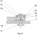
- FIG 6 A second embodiment is shown in FIG 6 .
- the plug contact 11 consists of two separate parts having a lower half 16 (constituting the first portion of the plug contact) that is completely, physically and electrically separated from the other part 17 (constituting the second portion of the plug contact).
- the lower part 16 of the plug contact would connect the electric circuit board 15 to the battery terminal 8 via the contact through the drilling 7 in the bolt 6, as in the previous embodiment.
- the upper part 17 of the plug contact connects the electric circuit board 15, through the wire 10 to external means.
- Such means could be battery level probes or any other needed pieces of equipment.
- a second wire, leading to the electronic circuit 18 on the electric circuit board 15 could also be included in this embodiment.
- the electric circuit board consists of a printed circuit totally encapsulated or potted in a suitable resin for increased durability and protection.
- the electric circuit board could also be housed in a thin-walled container 19, which could be manufactured in transparent insulating material such as polycarbonate, ABS, or any other material providing insulating and transparent properties.
- a light source in the form of a light emitting diode l.e.d. 18 is embedded in this circuitry during the potting stage.
- the status of this l.e.d. which is of the multi-color type in the present case, can be seen through the translucent lid 12, once the whole assembly is put together.
- the electric circuit board 15 comprises components required to have the device (such as the Abertax CLS) which measures or detects the electrolyte level within the battery. These components are directly supplied with power via the lower part 16 of the plug contact - all within the cup-shaped enclosure of the Perfect Connector 5.
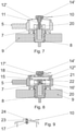
- FIG. 7 and Figure 8 Two further embodiments are shown in Figure 7 and Figure 8 :
- the parts 12, 13, and 14 comprising the cover for the Perfect Connector 5 are simplified whereby the lid 14' is fitted tight inside the cover 12'.
- a clipping feature as shown can also be provided.
- the material for lid 14' is a thermoplastic elastomer, which by its very nature provides a good seal when this is tightly fitted into another part, in this case 12', also made of thermoplastic elastomer or another suitable material, which would be easy to manufacture, while at the same time provide good sealing properties.
- a molded recess in the part 14' houses the second portion of the plug contact 11 together with the wire 10.
- cover 12' makes a good seal when this cover 12' is pressed in place on the rim of the cup-shaped portion of the Perfect Connector 5.
- FIG 8 shows a similar embodiment to Fig 7 , however, in this case the idea of having an embedded electronic circuit is included.
- This electronic circuit 15 is totally encapsulated in a suitable resin 21.
- This resin 21 could also be over-molded on the electronic components 15, with a suitable medium such as polyurethane or other suitable thermoplastic or resin.
- a suitable medium such as polyurethane or other suitable thermoplastic or resin.
- the inner circumferential wall of the cover 12" is extended in depth, to accommodate the necessary height to take the electronic circuitry together with the encapsulating medium 21.
- an l.e.d. 18 also embedded together with the electronic board and components, gives an indication of the status of the electronics.
- the cover 12" is made of translucent material to allow the light emitted from the l.e.d. 18 to be seen through the transparent potting resin or over-injected thermoplastic and through the translucent cover 12" itself.
- This l.e.d. 18 is of the multi-color type to monitor different status.
- One particular example is to monitor the temperature of the battery through its terminal 8 and the bolt 6.
- a temperature sensor 22 can be relatively easily installed directly from the electronic board and placed in contact with the bolt 6 which is tightened on directly to the battery terminal 8, thus, offering a good heat-conductive path for the temperature to be measured.
- a sleeve insert 20 is inserted into the drilling 7 of the bolt to have a better conductive connection between the first portion 16 or 16' of the plug contact 11 to the bolt 6.
- this insert sleeve is optional, only.
- Figure 9 shows the whole cover assembly molded as one piece 23.
- the cover 12" and lid 14' are molded together to form one whole piece.
- the wire 10 together with the second portion 17 of the plug contact are inserted through the special molded recess 24.
- the material chosen for this molding should ideally have good sealing properties and also possible to mould with translucent properties, for reasons already described above. It is also possible to do away with the recess 23 and over-mould the second portion 17 of the plug contact together with the wire 10.
- a suitable material which can be molded for this purpose would be a thermoplastic elastomer, also chosen for its acid-resisting properties.
- Figure 10 shows at the left top a top view on a spring and on the right an enlarged cross-sectional view of first and second portions of a plug contact together with part of a sleeve insert 20 for the drilling in the bolt.
- the sleeve insert 20 or the bolt 6 (if no sleeve insert is used), has a slot machined at a point around the inner surface thereof.
- a similar groove 25 is machined on the outer surface of the first portion of a modified plug contact 11'.
- An electrical-conductive spring 26 is fitted in the groove of the first portion of the modified plug contact 11'. This spring 26 locks in position when the first portion of the modified plug contact 11' is inserted in the hole of the sleeve insert 20. This provides a more stable physical connection against vibrations or other movements, while providing a better electrical connection between the modified plug contact 11' and the bolt 6.
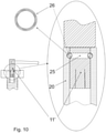
- FIG. 11 An alternative embodiment of a set consisting of the auxiliary battery connector and a battery having plural battery cells 28, 29, 30 each having at least two terminals is shown in Figure 11 .
- the upper part of Figure 11 shows an enlarged cross-sectional view of a terminal of a battery cell to which an auxiliary battery connector is attached.
- This auxiliary battery connector is to be utilized in instances for low and medium current applications, and replaces the standard inter-cell connectors.
- the pin contact is provided with a groove 25 and an electrical-conductive ring spring 26.
- the inner wall of the drilling in the terminal 8' is provided with a circular groove as well, thus allowing the ring spring 26 of the plug contact 11 to establish a snap connection between the plug contact 11 and the terminal 8'-
- the connector pin 11 is directly inserted into the drilling 7' in the terminal 8' without the need of additional attachment means such as a bolt.
- the whole connection is sealed against acid ingress by the molded cover 12" which is manufactured of soft plastic such as a suitable thermoplastic elastomers which clips onto a protrusion (clipping feature) 27 on the upper surface of the battery lid 9.
- a protrusion clipping feature
- Figure 11 schematically illustrates an example of three such cells connected together.
Landscapes
- Chemical & Material Sciences (AREA)
- Chemical Kinetics & Catalysis (AREA)
- Electrochemistry (AREA)
- General Chemical & Material Sciences (AREA)
- Inorganic Chemistry (AREA)
- Connection Of Batteries Or Terminals (AREA)
Abstract
Description
- The present invention generally relates to a connector for establishing an electrically conductive connection to terminals of battery cells or batteries. In particular the present inventions relates to connectors that may be used between battery cell terminals of a plurality of battery cells for the purpose of electrically connecting these battery cells with one another.
- Most types of rechargeable batteries such as a lead acid battery, a lithium-ion battery or a nickel-metal hydride battery consist of a number of battery cells. Terminals or poles of said battery cells are interconnected by inter-cell battery connectors in pairs to provide a series or parallel connection. Said inter-cell battery connectors are made of electrically conductive material such as metal. This is described in
WO 00/11730 A1 WO 2007/071425 A1 , for example. - In order to prevent corrosion and avoid short-circuits it is known to insulate both the inter-cell battery connectors and the mounting means that are used to connect the inter-cell battery connector to the respective battery cells. An example of such an improved inter-cell battery connector is referred to in the battery industry as "Perfect Connector". Said "Perfect Connector" is manufactured from copper cable which is provided with metal eyelets on both ends and has been fully encased in acid resistant thermoplastic elastomers except for the middle portion of the eyelets. Furthermore, the "Perfect Connector" is provided with a plastic cover covering bolts which are each passing through one of the eyelets and entering into a terminal of a battery cell in order to provide both a mechanical and electrical connection between the connector and the battery cells. These "Perfect Connectors" are widely used for inter-cell connections in batteries both for stationary and motive applications. They have been found to offer an ideal solution in sealing against acid-ingress, thus avoiding corrosion within the connection itself. The "Perfect Connectors" are bolted with an M10 bolt directly on to the terminals of the battery cells or to battery terminals providing a perfect electrical connection to the respective cells of the battery, while the bottom edge of the "Perfect Connector" also seals against the battery lid. The actual bolt is therefore "hidden" within the "Perfect Connector" when the latter is fitted with the cover. This cover also provides for sealing and protection of the electrical connection inside.
- During usage of a battery it is often necessary to provide an auxiliary supply of low and medium current from a battery in addition to the supply of full current via the connector that is attached to the terminal of a battery cell or a terminal of the battery. Such an auxiliary supply is referred to as "take-off connection" or "auxiliary connection" in the following. Take-off connections from batteries are always needed where low current applications have to be powered. In this respect, "low current" denotes a current that is about a magnitude smaller than the current that is supplied by the terminal during regular use of the battery. These may be several applications as required in a vehicle or other uses. One particular use is the powering of devices such as Battery Electrolyte Level Sensors or Battery Management Systems (BMS).
- A take-off connection which is still being widely used, due to its effectiveness in providing an ideal connection to a battery terminal, while at the same time, providing a very efficient seal between itself and the battery connectors is described in
EP 1 737 072 A2 - The "Washer with Leading Wire - (WLW)" was an improvement to a previous application of the applicant known as "Bolt with Leading Wire" (German utility model No:
DE 20 2005 009 694 U1 ). This comprised a bolt that had a wire radially fixed to one of its flat sides of its hexagonal head. The low current for any needed device such as a BMS was led through this wire, while the bolt itself (an M10 bolt) was used to tighten the connector to the terminal of a battery cell or battery, thus providing the high-current path. - From a technical point of view, said "Bolt with Leading Wire" had some negative aspects, as the wire, fixed to the bolt had obviously to be turned together with the bolt while the latter was being screwed and tightened on to the terminal, sandwiching the battery connector. It also often happened that in the final tightened position of the bolt, the wire was not in the ideal orientation as required. Any device such as a Level sensor or a BMS together with its associated wires and additional accessories had to be also twisted around with the bolt. This impracticability led to the "Washer with Leading Wire - (WLW)", whereby the ring, with the leading wire radially attached, is sandwiched and tightened between the bolt and the connector. Here the orientation of the ring and its radial wire could be adjusted to the correct orientation before the tightening of the main connector through screwing of the bolt took place.
- Some industrial OEM's in the Battery Industry are using the above described "Perfect Connectors" as preferred connectors, as this type of connector also provides a good sealing solution against acid-ingress to the connection. These "Perfect Connectors" are, however, hindering the use of the "Washer with Leading Wire - WLW".
- Another type of take-off connection to provide an auxiliary supply of low and medium current from a battery bases on providing an electrical contact to cable connectors between the different cells, as shown in
Figures 1, 2 and 3 . This take-off connection consists of a metal pin which is mounted in a plastic or insulating housing. This pin-connector-assembly 3, which also has a leading wire that is electrically connected to the metal pin, is mounted directly on acable 1, linking one cell to another in a battery. Thesecables 1 are connected to cell terminals (not shown) via an electricallyconductive bolt 2, which screws directly on to the cell terminal and is in electrical contact with acopper conductor wire 1b of thecable 1. Thepin connector 3 pierces acable insulation 1a and thecopper conductor wire 1b. Thepin connector 3 is held in place with a standard cable-tie or strap (not shown). This is a very convenient and quick way of providing a take-off connection from anybattery cable 1. However, it has been proven, that this setup is highly prone to corrosion, as it does not offer an efficient sealing between itself and the piercedbattery cable 1. In the usual battery environment, where battery acid such as Sulfuric Acid is present (also in vapor form), this acid enters into a gap between the pin-connector-assembly 3 and thecable 1, and causes severe corrosion 4. Since theinsulation 1a of thecable 1 is pierced, the acid or its vapor are even allowed to find their way to thecopper conductor wire 1b within thecable 1. For this reason, this type of take-off connection that pierces the insulation of an electrical conductor is actually a primitive and irresponsible method in the electrical technology practice. There is also a risk of an electric shock to the user especially for voltages above 48 V DC. - Thus, it is the objective of the present invention to provide an improved auxiliary battery connector allowing a flexible and secure take-off connection and thus an auxiliary supply of low and medium current in addition to a main current supply provided via the connector itself.
- The above objective is solved by the combination of features of the independent claims. Preferred embodiments are described in the dependent claims.
- Embodiments provide an auxiliary battery connector to be used in conjunction with a battery. The auxiliary battery connector comprises a plug contact and an insulated wire. The plug contact has two portions at opposite sides of the plug contact, wherein a first portion of the plug contact is adapted to plug to an engagement portion of the terminal or a tool engagement portion of a bolt for tightening a main battery connector to the terminal of a battery cell or a terminal of the battery. The battery terminal is usually forming part of a battery lid and may be belonging to an individual battery cell or the battery as a whole. The insulated wire has as conductor which is electrically connected to a second portion of the plug contact different from the first portion of the plug contact.
- Due to the above configuration the auxiliary battery connector is capable to take-off current from the battery terminal. As a diameter of the conductor of the insulated wire is usually much lower than a diameter of a conductor of a main battery connector, the auxiliary battery connector is suitable for a current that is lower by about one magnitude than the main battery connector, only.
- According to an embodiment the insulated wire is electrically connected to the second portion of the plug contact by soldering, welding, screwing or any other means such as crimping, which provides a good electrical connection between the wire and plug contact.
- According to an embodiment, the auxiliary battery connector further comprises a lid of insulating material, the lid comprising a recess, the recess being adapted to receive the second portion of the plug contact together with a portion of the insulated wire. Thus, by using such a lid it is possible to insulate the first portion of the plug contact which is protruding from the engagement portion of the terminal or the tool engagement portion of the bolt, respectively after the plug contact has been plugged to the engagement portion of the terminal or the tool engagement portion of the bolt. This prevents hazard due to electricity and protects the contact against humidity and acid.
- According to an embodiment, the first portion of the plug contact provides a pin contact with circular cross section, the pin contact being thus adapted to enter a (circular) drilling in the engagement portion of the terminal or in the tool engagement portion of the bolt. According to an alternative embodiment, the first portion of the plug contact provides a pin contact with hexagonal cross section or splined cross section or any other cross section, the pin contact being thus adapted to enter a hexagonal socket or splined socket (or a socket having the other cross section) constituting the tool engagement portion of the bolt or constituting a tool engagement portion of the terminal. According to an alternative embodiment, the first portion of the plug contact provides a tube-shaped end portion with circular cross section, the tube-shaped end portion being thus adapted to engage a circular outer surface of the terminal or a circular tool engagement portion of the bolt. According to an alternative embodiment, the first portion of the plug contact provides a tube-shaped end portion with hexagonal cross section, the tube-shaped end portion being thus adapted to engage around a hexagonal outer surface of the terminal or a hexagonal tool engagement portion of the bolt.
- According to an embodiment, the first portion of the plug contact is provided with elastic contact blades, thus providing a connection which is constantly under radial tension due to its springiness and is providing good electrical conductivity between the plug contact and the respective terminal bolt.
- According to an embodiment the first portion of the plug contact provides a tube-shaped end portion with circular cross section and is provided with a circular groove on its radial surface area, wherein an electrical-conductive ring spring is fitted into the groove. When the pin contact is inserted in the (circular) drilling (or sleeve insert of the drilling) in the engagement portion of the terminal or in the tool engagement portion of the bolt, this spring provides a constant tension and guarantees a good electrical contact while the pin contact is still rotatable about its central axis. According to an embodiment, the drilling (or sleeve insert of the drilling) in the engagement portion of the terminal or in the tool engagement portion of the bolt has a circular groove machined on the inner surface of the drilling (or sleeve insert), thus allowing the ring spring to partially enter this groove as well. In consequence, the pin contact is capable to snap into the respective engagement portion.
- Embodiments of a set consist of an auxiliary battery connector as described above, a main battery connector (such as an inter-cell battery connector, for example) and an electrically conductive bolt. The main battery connector being manufactured from copper cable which is provided with a metal eyelet on one or both ends and has been fully encased in acid resistant thermoplastic elastomers. An inter-cell battery connector that can be used as main battery connector is known as "Perfect Connector" and described in detail above. The electrically conductive bolt is adapted to the eyelet of the main battery connector and adapted to attach the eyelet to a terminal of a battery cell or a terminal of a battery.
- According to an embodiment, the tool engagement portion of the bolt is drilled in its central axis and the first portion of the plug contact provides a pin contact with circular cross section, the pin contact being adapted to enter the drilling in the tool engagement portion of the bolt in sliding fit or press fit. Thus, it is possible to removably attach the plug contact to bolts having e.g. a tool engagement portion with hexagonal cross section. Such kind of bolt is often used together with "Perfect Connectors". In case the pin contact of the plug contact is further provided with elastic contact blades which collapse radially inwards when the pin contact is inserted into the drilling in the tool engagement portion of the bolt, there is a constant radial tension between the pin contact and the inner wall of the drilling, thus guaranteeing a good electrical connection while it is still possible to rotate the pin contact about its central axis.
- According to an embodiment, the set additionally comprises a sleeve insert provided in-between the drilling in the tool engagement portion of the bolt and the contact pin.
- According to an embodiment, the acid resistant rubber or soft plastics such as thermoplastic elastomers encasing the main battery connector provide a cup-shaped portions on one or both ends of the main battery connector, wherein the bottom of the cup-shaped portion is formed by one metal eyelet, the acid resistant rubber or soft plastics such as thermoplastics thus surrounding the at least one metal eyelet. Furthermore, the auxiliary battery connector comprises the above discussed lid and a cover which is made of an acid-resisting material and adapted to provide a sealing effect between the cup-shaped portions of the acid resistant rubber or soft plastics such as thermoplastics of the main battery connector and the lid. Both the lid and the cover may be manufactured from a plastic material, thermoplastic elastomer material or rubber or soft plastics or any other material that offers a good seal between the lid and the acid resistant rubber or soft plastics such as thermoplastic elastomers of the main battery connector.
- According to an embodiment, the cover is ring-shaped and provided with a hole in its center. Furthermore, wherein the lid is tightly fitted in the hole of the cover and the outer portion of the cover engages with the cup-shaped portion of the acid resistant rubber or soft plastics such as thermoplastics of the main battery connector.
- According to an embodiment, the connector is made of a hard plastic material and both the lid and the acid resistant rubber are made from a soft plastic material such as thermoplastic elastomers.
- According to an embodiment, the set further comprises a sleeve made of a good sealing material (such as e.g. rubber or soft plastics such as thermoplastic elastomers), wherein the plug contact is hosted inside the sleeve in such a way that the first portion of the plug contact is protruding from the sleeve and engaging the bolt whereas the second portion of the plug contract is fitted through the lid.
- According to an embodiment, the cover, the sleeve and the lid are integrally manufactured in one piece, such providing a simplified lid that seals around the mated parts. Material for this simplified lid would be thermoplastic elastomer, or other material which offers a good sealing possibility. Optionally, the simplified lid (one piece) provides an extended circumferential inner wall, deep enough to accommodate an electronic circuitry together with all the parts potted together or over-molded. The outer rim of this simplified lid would seal tight against the rim of the cup-shaped portions of the acid resistant rubber or soft plastics such as thermoplastic elastomers encasing the main battery connector if these elements are clipped together.
- According to an embodiment, the set further comprises a light source electrically connected to the plug contact and hosted in the cup-shaped portion of the acid resistant rubber or soft plastics such as thermoplastic elastomers encasing the main battery connector. Moreover, the cover or the lid is made from acid-resistant translucent material, such that any light, originating from the light source (such as a light emitting diode or multicolor light emitting diode, for example) could be seen through the cover respectively lid.
- According to an embodiment the plug contact consists of two parts that are mounted together, wherein a first part provides the first portion of the plug contact and a second part provides the second portion of the plug contact. According to an alternative embodiment, the plug contact is integrally formed in one piece.
- According to an embodiment, the set further comprises an electronic circuit mounted inside the cup-shaped portion of the acid resistant rubber or soft plastics such as thermoplastic elastomers encasing the main battery connector above the bolt (thus, the bolt is located between the eyelet of the main battery connector and the electronic circuit), the electric circuit being electrically connected to the plug contact. Thus, the electronic circuit is insulated by the cup-shaped portions of the acid resistant rubber or soft plastics such as thermoplastic elastomers and the lid. The electronic circuit can be potted or not and is placed inside the cup-shaped portion of the acid resistant rubber or soft plastics such as thermoplastic elastomers such that it obtains power from the first portion of the plug contact which is inserted into the central drilling of the bolt. According to an embodiment, the electronic circuit comprises a light source which enables a user to monitor, through a translucent lid, the electronic status of the assembly, such as the state of the external accessory - as for example, the electrolyte level of the battery, through a connected external probe, or other information, via the insulated wire attached to the second portion of the plug contact.
- According to an embodiment, the set further comprises a sleeve insert which is inserted into the drilling of the bolt for receiving the first portion of the plug contact to make a better sliding connection with improved electrical conductivity.
- According to an embodiment, the electronic circuit comprises a thermo-sensor, which protrudes from the electronic circuit in such a way that it makes physical contact with the bolt when all components of the set are in place. The bolt which is tightened into the battery terminal, would conduct the heat from the battery to the thermo-sensor, where the temperature would be monitored by the electronic circuit and any over-temperature would be indicated by the light source.
- Alternative embodiments of a set consist of an auxiliary battery connector as described above and a battery having plural battery cells. Each battery cell has (at least or exactly) two terminals. At least one (or preferably all) terminal is drilled along its central axis. This drilling may be identical with or different from the inner thread of the terminal that is adapted to receive the bolt as described above. The first portion of the plug contact provides a pin contact with circular cross section. The pin contact may be provided with or without elastic contact blades. The pin contact is adapted to enter the drilling in the terminal. Thus, by using the auxiliary battery connector it is possible to provide an inter-cell battery connector that is suitable for low and medium current applications. As the pin contact can be freely rotated about its central axis, the insulated wire that is attached to the second portion of the plug contact can be arranged as desired. Furthermore, this type of inter-cell battery connector can be mounted without the need of tools.
- According to an embodiment, the drilling in the terminal has a circular groove machined on the inner surface thereof and is thus capable to receive a ring spring of the pin contact. In case the first portion of the plug contact is provided with a circular groove on its radial outer surface area and an electrical-conductive ring spring is fitted into the groove, the spring provides a constant tension and guarantees a good electrical contact while the pin contact is still rotatable about its central axis
- According to an embodiment, the set further comprises a ring-shaped cover which is made of an acid-resisting material and adapted to provide a sealing effect between a lid of the auxiliary battery connector and a housing of the battery cells. The housing of each battery cell comprises circular protrusions surrounding at least one and preferably each terminal of the battery cell. The cover comprises a circular groove that is adapted to tightly receive the circular protrusion. Finally, the cover is provided with a hole in its center that is adapted to tightly receive the lid, preferably in a snap-fit manner. Thus, the cover and the lid together provide a perfect insulation of the plug contact of the auxiliary battery connector and the terminal of the battery cell. This prevents corrosion of the terminal or plug contact.
- It is an advantage of the above described solution that it provides for a better electrical connection of the auxiliary battery connector that is used to take-off current from the battery terminal while affording better physical stability against vibration and other similar mechanical forces.
- In the following, embodiments of the present invention are described by referring to the enclosed Figures in which
- Figures 1 to 3
- schematically show cross-sectional views of a take-off connection according to the prior art;
- Figures 4 and 5
- schematically show a first embodiment of a set consisting of an auxiliary battery connector, a main battery connector and an electrically conductive bolt in exploded view (
figure 4 ) and cross-sectional view in a mounted state (figure 5 ); - Figure 6
- schematically shows a cross-sectional view of a second embodiment of the set;
- Figure 7
- schematically shows a cross-sectional view of a third embodiment of the set;
- Figure 8
- schematically shows a cross-sectional view of a fourth embodiment of the set;
- Figure 9
- schematically shows a cross-sectional view of a one piece cover that may be used in the set;
- Figure 10
- schematically shows details of a plug contact that may be used in the set; and
- Figure 11
- schematically shows an alternative embodiment of a set consisting of an auxiliary battery connector and a battery having plural battery cells each having two terminals.
-
Figure 4 and Figure 5 each show a cross-section of a connection between an inter-cell battery connector (main battery connector) 5 and abattery terminal 8 which is integrated in abattery lid 9. Theinter-cell battery connector 5 is manufactured from copper cable that is provided with metal eyelets on both ends and has been fully encased in acid resistant rubber or soft plastics such as thermoplastics. Theinter-cell battery connector 5 is referred to as "Perfect Connector" 5 in the following. -
Figure 4 shows a split view (exploded view) with all the separate components utilized, whileFigure 5 shows an assembled view. - The connection between the
Perfect Connector 5 and thebattery terminal 8 is tightened by thebolt 6 to thebattery terminal 8. Under usual conditions a cup-shaped portion of acid resistant rubber surrounding each metal eyelet of thePerfect Connector 5 is protected by means of acover 12 and alid 14. Thiscover 12 andlid 14 provide a good seal from the outside ambient environment to the inside of the cup-shaped portion of thePerfect Connector 5, thus preventing any corrosion between the conductive part of thePerfect Connector 5 and thebattery terminal 8. The lower edge of thePerfect connector 5 presses tightly against the surface of thebattery lid 9 and is also fitted tight against the upper part ofbattery terminal 8. This is the exposed part of the battery terminal above thebattery lid 9. The remainder lower part of the same battery terminal is embedded within the construction of thebattery lid 9. This tight-fitting assembly between the "Perfect Connector" 5 and thebattery terminal 8 also provides a good seal against any possible acid-ingress to the inside of the cup-shaped portion of thePerfect Connector 5, and underneath of thePerfect Connector 5. - The way that the
Perfect Connectors 5 are sealed, presents a challenge when it is necessary to take-off a low-current supply from thesame battery terminal 8 using an auxiliary battery connector, without spoiling the sealing effect of thePerfect Connector 5. The present invention, here described, is especially designed to be used wherever these "Perfect Connectors" are involved. - This particular novelty hereby described, actually provides for such a connection in a very simple but effective manner.
FIG 5 illustrates how this is achieved. - The
cover 12 is provided with a hole in its center, through which the-lid 14 made of soft plastic such as a thermoplastic elastomer or other acid-resistant sealing material such as rubber, is fitted. Thislid 14 could also be made of a harder insulating material such as polypropylene, polycarbonate or similar suitable material. Asecondary sealing element 13 is additionally used in this assembly. The material of thelid 12 is selected as suitable for providing a seal around its circumference when clipped in place on to the cup-shaped portion of the "Perfect connector" 5. Such material would be soft polypropylene or a suitable thermoplastic elastomer, or similar material. - The
bolt 6 which is used to tighten thePerfect Connector 5 to thebattery terminal 8 is drilled in its center. Thiscentral drilling 7 provides a hole for a plug-in connection to aplug contact 11, which leads the current from thebattery terminal 8 through awire 10 which is electrically connected to theplug contact 11. This wire 10 (which is preferably insulated) can be electrically and physically connected to theplug contact 11 at a second portion (a first portion will be described below) in various ways, such as being soldered, welded or crimped. Any low or even medium current device such as a level sensor or BMS or any other device, can be supplied via thewire 10. Thiswire 10 if fitted tight inside thelid 14, thus ensuring a good and effective seal between thewire 10 and thelid 14. - The lower part (first portion) of
plug contact 11 consists of a part, suitably designed to make good electrical contact with theinner drilling 7 of thebolt 6. This is best achieved by having this part of theplug contact 11 springy in nature, such that it is made in segments which can move radially inwards when inserted in thedrilling 7, therefore ensuring that the outer circumferential area of the first portion ofplug contact 11 makes a good contact to the inner surface ofdrilling 7 when the two parts -plug contact 11 and drilling 7 - are paired together. - The
plug contact 11 is inserted into thePerfect Connector 5 through thesleeve 13 and thecover 12, thereby ensuring that the lower part (first portion) of theplug contact 11 is guided into thedrilling 7 to make a good connection. The upper central round part (second portion) of the body of theplug contact 11 is fitted tight into a recess inlid 14, again ensuring a perfect seal, against any ingress between theplug contact 11, thesecondary lid 14 and thecover 12. Thelatter cover 12, owing to the material that it is made from, such as soft polypropylene, TPE or any other suitable material, that is also battery-acid proof, makes a good tight seal between itself and the circumferential edge of thePerfect Connector 5. - All this provides for a simple but effective and sealed connection, which also makes it very easy in the field to provide such a connection.
- A second embodiment is shown in
FIG 6 . This shows another novel idea, in which the space available between thebolt 6 and thecover 12 is utilized for housing special circuitry such as anelectric circuit board 15. In this case theplug contact 11 consists of two separate parts having a lower half 16 (constituting the first portion of the plug contact) that is completely, physically and electrically separated from the other part 17 (constituting the second portion of the plug contact). Thelower part 16 of the plug contact would connect theelectric circuit board 15 to thebattery terminal 8 via the contact through thedrilling 7 in thebolt 6, as in the previous embodiment. - The
upper part 17 of the plug contact connects theelectric circuit board 15, through thewire 10 to external means. Such means could be battery level probes or any other needed pieces of equipment. A second wire, leading to theelectronic circuit 18 on theelectric circuit board 15 could also be included in this embodiment. - In the present embodiment, the electric circuit board consists of a printed circuit totally encapsulated or potted in a suitable resin for increased durability and protection. However, this is not mandatory. As an alternative, the electric circuit board could also be housed in a thin-
walled container 19, which could be manufactured in transparent insulating material such as polycarbonate, ABS, or any other material providing insulating and transparent properties. - Furthermore, as a means of visually monitoring the electronic status of the whole embodiment, a light source in the form of a light emitting diode l.e.d. 18 is embedded in this circuitry during the potting stage. The status of this l.e.d. which is of the multi-color type in the present case, can be seen through the
translucent lid 12, once the whole assembly is put together. In the present embodiment theelectric circuit board 15 comprises components required to have the device (such as the Abertax CLS) which measures or detects the electrolyte level within the battery. These components are directly supplied with power via thelower part 16 of the plug contact - all within the cup-shaped enclosure of thePerfect Connector 5. - Two further embodiments are shown in
Figure 7 and Figure 8 :
In these two embodiments, theparts Perfect Connector 5 are simplified whereby the lid 14' is fitted tight inside the cover 12'. A clipping feature as shown can also be provided. The material for lid 14' is a thermoplastic elastomer, which by its very nature provides a good seal when this is tightly fitted into another part, in this case 12', also made of thermoplastic elastomer or another suitable material, which would be easy to manufacture, while at the same time provide good sealing properties. A molded recess in the part 14' houses the second portion of theplug contact 11 together with thewire 10. As an alternative, it is possible to over-mould the second portion of theplug contact 11 and thewire 10 within the lid 14'. - The outer circumferential lip on cover 12' makes a good seal when this cover 12' is pressed in place on the rim of the cup-shaped portion of the
Perfect Connector 5. -
Figure 8 shows a similar embodiment toFig 7 , however, in this case the idea of having an embedded electronic circuit is included. Thiselectronic circuit 15 is totally encapsulated in asuitable resin 21. Thisresin 21 could also be over-molded on theelectronic components 15, with a suitable medium such as polyurethane or other suitable thermoplastic or resin. For this end, the inner circumferential wall of thecover 12" is extended in depth, to accommodate the necessary height to take the electronic circuitry together with the encapsulatingmedium 21. - An l.e.d. 18 also embedded together with the electronic board and components, gives an indication of the status of the electronics. In this case the
cover 12" is made of translucent material to allow the light emitted from the l.e.d. 18 to be seen through the transparent potting resin or over-injected thermoplastic and through thetranslucent cover 12" itself. This l.e.d. 18 is of the multi-color type to monitor different status. - One particular example is to monitor the temperature of the battery through its
terminal 8 and thebolt 6. Such atemperature sensor 22 can be relatively easily installed directly from the electronic board and placed in contact with thebolt 6 which is tightened on directly to thebattery terminal 8, thus, offering a good heat-conductive path for the temperature to be measured. - All metal parts, 16', 17' and 22 could directly form part of the printed circuit board with all the other electronic components. Thus, the
plug contact 11 can form part of the electric circuit board. Finally, this is all potted together with the insulatingmedium 21 as mentioned earlier, thus providing a very suitable assembly for plugging it as one unit to obtain the desired connection from thebolt 6 to any external unit (such as a level-sensor probe, or other), viawire 10. All the electronic circuitry for the correct operation of the whole unit is therefore contained within thePerfect Connector 5. - In the present embodiment, a
sleeve insert 20 is inserted into thedrilling 7 of the bolt to have a better conductive connection between thefirst portion 16 or 16' of theplug contact 11 to thebolt 6. However, this insert sleeve is optional, only. -
Figure 9 , shows the whole cover assembly molded as onepiece 23. Here, thecover 12" and lid 14' are molded together to form one whole piece. Thewire 10 together with thesecond portion 17 of the plug contact are inserted through the special moldedrecess 24. The material chosen for this molding should ideally have good sealing properties and also possible to mould with translucent properties, for reasons already described above. It is also possible to do away with therecess 23 and over-mould thesecond portion 17 of the plug contact together with thewire 10. A suitable material which can be molded for this purpose would be a thermoplastic elastomer, also chosen for its acid-resisting properties. - A further embodiment is shown in
Figure 10. Figure 10 shows at the left top a top view on a spring and on the right an enlarged cross-sectional view of first and second portions of a plug contact together with part of asleeve insert 20 for the drilling in the bolt. In this embodiment thesleeve insert 20 or the bolt 6 (if no sleeve insert is used), has a slot machined at a point around the inner surface thereof. Asimilar groove 25 is machined on the outer surface of the first portion of a modified plug contact 11'. - An electrical-
conductive spring 26 is fitted in the groove of the first portion of the modified plug contact 11'. Thisspring 26 locks in position when the first portion of the modified plug contact 11' is inserted in the hole of thesleeve insert 20. This provides a more stable physical connection against vibrations or other movements, while providing a better electrical connection between the modified plug contact 11' and thebolt 6. - An alternative embodiment of a set consisting of the auxiliary battery connector and a battery having
plural battery cells Figure 11 . The upper part ofFigure 11 shows an enlarged cross-sectional view of a terminal of a battery cell to which an auxiliary battery connector is attached. This auxiliary battery connector is to be utilized in instances for low and medium current applications, and replaces the standard inter-cell connectors. - The basic electrical connection is described in the previous embodiments with reference to
Figure 10 with the difference that theplug contact 11 is not attached to a sleeve insert in a drilling of the bolt, but directly in a drilling in the terminal 8' of thebattery cell 28. Although this drilling could be the inner thread of the terminal that is usually receiving the bolt as described above, it is preferred that the drilling has a smaller diameter and substantially smooth inner walls, thus requiring a specifically designed terminal 8' which does not take thebolt 6 as in the previously described embodiments. - As in the embodiment of
Figure 10 , the pin contact is provided with agroove 25 and an electrical-conductive ring spring 26. The inner wall of the drilling in the terminal 8' is provided with a circular groove as well, thus allowing thering spring 26 of theplug contact 11 to establish a snap connection between theplug contact 11 and the terminal 8'- - The
connector pin 11 is directly inserted into the drilling 7' in the terminal 8' without the need of additional attachment means such as a bolt. - The advantages of such a structure is that it allows to provide a particular fast, easy and cheap inter-cell connection using the auxiliary battery connector. This connection is still flexible, as the wire 10' together with the
plug contact 11 is able to rotate around a central axis of theplug contact 11 and thus is capable to find its own orientation. - The whole connection is sealed against acid ingress by the molded
cover 12" which is manufactured of soft plastic such as a suitable thermoplastic elastomers which clips onto a protrusion (clipping feature) 27 on the upper surface of thebattery lid 9. As theprotrusion 27 is surrounding the terminal 8' this provides a good sealing of the complete connection against the battery lid. - The lower part of
Figure 11 schematically illustrates an example of three such cells connected together.
Claims (15)
- An auxiliary battery connector to be used in conjunction with a battery, the auxiliary battery connector being capable to take-off current from a battery terminal (8),
the auxiliary battery connector comprising:a plug contact (11) having two portions, wherein a first portion of the plug contact (11) is adapted to plug to an engagement portion (7a) of the terminal (8) or a tool engagement portion (7) of a bolt (6) which is attached to the battery terminal (8); andan insulated wire (10), the conductor of which is electrically connected to the plug contact (11) at a second portion of the plug contact (11) different from the first portion of the plug contact (11). - The auxiliary battery connector of claim 1, further comprising:
a lid (14) of insulating material, the lid (14) comprising a recess, the recess being adapted to receive the second portion of the plug contact (11) together with a portion of the insulated wire (10). - The auxiliary battery connector of claim 1 or 2,
wherein the first portion of the plug contact (11) provides a pin contact with circular cross section with or without elastic contact blades, the pin contact being thus adapted to enter a drilling in the engagement portion of the terminal or in the tool engagement portion (7) of the bolt (6); or
wherein the first portion of the plug contact (11) provides a pin contact with hexagonal cross section or splined cross-section with or without elastic contact blades, the pin contact being thus adapted to enter a hexagonal socket or splined socket constituting the tool engagement portion (7) of the terminal or of the bolt (6); or
wherein the first portion of the plug contact (11) provides a tube-shaped end portion with circular cross section with or without elastic contact blades, the tube-shaped end portion being thus adapted to engage around a circular outer surface of the terminal or a circular tool engagement portion (7) of the bolt (6);
wherein the first portion of the plug contact (11) provides a tube-shaped end portion with hexagonal cross section with or without elastic contact blades, the tube-shaped end portion being thus adapted to engage around a hexagonal outer surface of the terminal or a hexagonal tool engagement portion (7) of the bolt (6). - The auxiliary battery connector of claim 1 or 2, wherein the first portion of the plug contact (11) provides a tube-shaped end portion with circular cross section and is provided with a circular groove (25) on its radial surface area, in which an electrical-conductive ring spring (26) is fitted.
- A set consisting of
an auxiliary battery connector of one of claims 1 to 4;
a main battery connector (5), the main battery connector (5) being manufactured from copper cable which is provided with a metal eyelet on at least one end and has been fully encased in acid resistant rubber or thermoplastic elastomers; and an electrically conductive bolt (6) that is adapted to the eyelet of the main battery connector (5). - The set of claim 5, whereby the tool engagement portion (7) of the bolt (6) is drilled in its central axis and the first portion of the plug contact (11) provides a pin contact with circular cross section with or without elastic contact blades, the pin contact being adapted to enter the drilling in the tool engagement portion (7) of the bolt (6), wherein the drilling in the tool engagement portion (7) of the bolt (6) optionally has a circular groove machined on the inner surface of the drilling.
- The set of claim 5 or 6,
wherein the acid resistant rubber or thermoplastic elastomers encasing the main battery connector (5) provides a cup-shaped portion on at least one end of the main battery connector (5), wherein the bottom of the cup-shaped portion is formed by one metal eyelet, the acid resistant rubber thus surrounding the at least one metal eyelet; and
wherein the auxiliary battery connector further comprisesa lid (14) of insulating material, the lid (14) comprising a recess, the recess being adapted to receive the second portion of the plug contact (11) together with a portion of the insulated wire (10); anda cover (12) which is made of an acid-resisting material and adapted to provide a sealing effect between the cup-shaped portion of the acid resistant rubber or thermoplastic elastomers of the main battery connector (5) and the lid (4). - The set of claim 7,
wherein the cover (12) is ring-shaped and provided with a hole in its center; and wherein the lid (14) is tightly fitted in the hole of the cover (12) and the outer portion of the cover (12) engages with the cup-shaped portion of the acid resistant rubber or thermoplastic elastomers of the main battery connector (5). - The set of claim 7 or 8, further comprising a sleeve (13), which is made of a sealing material, wherein the plug contact (11) is hosted inside the sleeve (13) in such a way that the first portion of the plug contact (11) is protruding from the sleeve (13) and engaging the bolt (6) whereas the second portion of the plug contract (11) is fitted through the lid (14).
- The system of claim 9, wherein the cover (12), the sleeve (13) and the lid (14) are integrally manufactured in one piece (23), the piece (23) optionally providing an extended circumferential inner wall, deep enough to accommodate an electronic circuitry.
- The set of one of claims 7 to 10,
further comprising a light source (18) electrically connected to the plug contact (11) and hosted in the cup-shaped portions of the acid resistant rubber or thermoplastic elastomers encasing the main battery connector (5),
wherein the cover (12) or the lid (14) is made from acid-resistant translucent material. - The set of one of claims 7 to 11,
further comprising an electronic circuit (15) mounted inside the cup-shaped portion of the acid resistant rubber or thermoplastic elastomers encasing the main battery connector (5) above the bolt (6), the electric circuit (15) being electrically connected to the plug contact (11), wherein the electronic circuit (15) optionally comprises a thermo-sensor (22), which protrudes from the electronic circuit (15) in such a way that it makes physical contact with the bolt (6) when all components of the set are in place. - The set of one of claims 7 to 12, further comprising a sleeve insert (20) which is inserted into a drilling (7) of the bolt (6) for receiving the first portion of the plug contact (11).
- Set consisting of
an auxiliary battery connector of one of claims 1 to 4; and
a battery having plural battery cells (28, 29, 30) each having at least two terminals (8'),
wherein the terminals (8') are drilled along their central axes and the first portion of the plug contact (11) provides a pin contact with circular cross section with or without elastic contact blades, the pin contact being adapted to enter the drilling (7') in the terminals (8'), wherein the drillings in the terminals (8') optionally have a circular groove machined on the inner surface of the respective drilling. - Set of claim 14,
further comprising a ring-shaped cover (12") which is made of an acid-resisting material and adapted to provide a sealing effect between a lid (14") of the auxiliary battery connector and a housing of the battery cells (28, 29, 30),
wherein the housing of each battery cell (28, 29, 30) comprises circular protrusions (27) surrounding at least one terminal (8') of the battery cell (28, 29, 30),
wherein the cover (12') comprises a circular groove that is adapted to tightly receive one of the circular protrusions (27), and
wherein the cover (12') is provided with a hole in its center that is adapted to tightly receive the lid (14").
Priority Applications (2)
| Application Number | Priority Date | Filing Date | Title |
|---|---|---|---|
| PL20185549.1T PL3940887T3 (en) | 2020-07-13 | 2020-07-13 | Auxiliary connector for a battery |
| EP20185549.1A EP3940887B1 (en) | 2020-07-13 | 2020-07-13 | Auxiliary connector for a battery |
Applications Claiming Priority (1)
| Application Number | Priority Date | Filing Date | Title |
|---|---|---|---|
| EP20185549.1A EP3940887B1 (en) | 2020-07-13 | 2020-07-13 | Auxiliary connector for a battery |
Publications (2)
| Publication Number | Publication Date |
|---|---|
| EP3940887A1 true EP3940887A1 (en) | 2022-01-19 |
| EP3940887B1 EP3940887B1 (en) | 2025-12-03 |
Family
ID=71607815
Family Applications (1)
| Application Number | Title | Priority Date | Filing Date |
|---|---|---|---|
| EP20185549.1A Active EP3940887B1 (en) | 2020-07-13 | 2020-07-13 | Auxiliary connector for a battery |
Country Status (2)
| Country | Link |
|---|---|
| EP (1) | EP3940887B1 (en) |
| PL (1) | PL3940887T3 (en) |
Citations (7)
| Publication number | Priority date | Publication date | Assignee | Title |
|---|---|---|---|---|
| US4643511A (en) * | 1985-12-19 | 1987-02-17 | System Material Handling Company | Auxiliary wire connections for side post batteries |
| US5620338A (en) * | 1994-08-25 | 1997-04-15 | Paccar Inc. | Universal battery cable assembly |
| WO2000011730A1 (en) | 1998-08-23 | 2000-03-02 | Ovonic Battery Company, Inc. | Monoblock battery assembly |
| DE202005009694U1 (en) | 2005-06-21 | 2006-11-02 | Abertax Research And Development Ltd. | Screw for electrical cable connection in e.g. vehicle battery, has thread shaft and head, where stripped end of electrical cable is fixed in radial borehole of head by pressing, soldering, welding, sticking, clamping or screwing process |
| EP1737072A2 (en) | 2005-06-21 | 2006-12-27 | Abertax Research And Development Ltd. | Cable connection system for battery connectors |
| WO2007071425A1 (en) | 2005-12-23 | 2007-06-28 | Hille & Müller GMBH | Plate or strip for producing connectors, connector and use thereof, and process for manufacturing such a strip |
| EP2876707A1 (en) * | 2012-07-23 | 2015-05-27 | SK Innovation Co., Ltd. | Device for connecting battery module electrode terminal and terminal |
Family Cites Families (2)
| Publication number | Priority date | Publication date | Assignee | Title |
|---|---|---|---|---|
| US6848922B2 (en) * | 2003-03-10 | 2005-02-01 | Hypertronics Corporation | Socket contact with integrally formed arc arresting portion |
| GB2484327B (en) * | 2010-10-07 | 2015-05-13 | Tyco Electronics Ltd Uk | A connector system |
-
2020
- 2020-07-13 EP EP20185549.1A patent/EP3940887B1/en active Active
- 2020-07-13 PL PL20185549.1T patent/PL3940887T3/en unknown
Patent Citations (7)
| Publication number | Priority date | Publication date | Assignee | Title |
|---|---|---|---|---|
| US4643511A (en) * | 1985-12-19 | 1987-02-17 | System Material Handling Company | Auxiliary wire connections for side post batteries |
| US5620338A (en) * | 1994-08-25 | 1997-04-15 | Paccar Inc. | Universal battery cable assembly |
| WO2000011730A1 (en) | 1998-08-23 | 2000-03-02 | Ovonic Battery Company, Inc. | Monoblock battery assembly |
| DE202005009694U1 (en) | 2005-06-21 | 2006-11-02 | Abertax Research And Development Ltd. | Screw for electrical cable connection in e.g. vehicle battery, has thread shaft and head, where stripped end of electrical cable is fixed in radial borehole of head by pressing, soldering, welding, sticking, clamping or screwing process |
| EP1737072A2 (en) | 2005-06-21 | 2006-12-27 | Abertax Research And Development Ltd. | Cable connection system for battery connectors |
| WO2007071425A1 (en) | 2005-12-23 | 2007-06-28 | Hille & Müller GMBH | Plate or strip for producing connectors, connector and use thereof, and process for manufacturing such a strip |
| EP2876707A1 (en) * | 2012-07-23 | 2015-05-27 | SK Innovation Co., Ltd. | Device for connecting battery module electrode terminal and terminal |
Also Published As
| Publication number | Publication date |
|---|---|
| EP3940887B1 (en) | 2025-12-03 |
| PL3940887T3 (en) | 2026-04-20 |
Similar Documents
| Publication | Publication Date | Title |
|---|---|---|
| US10224532B2 (en) | Detection module | |
| US20220252231A1 (en) | Rechargeable battery with lighting | |
| CN109075499A (en) | Magnetic pole button | |
| US20130252032A1 (en) | Battery module | |
| KR20180020269A (en) | Battery module with temperature monitoring assembly | |
| US5449570A (en) | Connection arrangement for battery monitoring circuits | |
| US11769913B2 (en) | Storage battery device for a battery pack of a handheld power tool | |
| HK1252750A1 (en) | Electric energy storage module | |
| US9685720B1 (en) | Connector structure for flexible light strip | |
| JP5915460B2 (en) | Temperature sensor mounting structure and wiring module manufacturing method | |
| US9936594B2 (en) | Wiring module | |
| US9806435B2 (en) | Insulation piercing battery connector | |
| EP3940887B1 (en) | Auxiliary connector for a battery | |
| US20140266230A1 (en) | Battery Electrolyte Level Monitor | |
| US7897275B2 (en) | Electrical rechargeable battery | |
| CN217691537U (en) | Battery pack | |
| CN213212389U (en) | Thread electricity taking device | |
| US10005374B2 (en) | Prismatic accumulator cell and accumulator pack | |
| CN113394508A (en) | Battery module | |
| CN223693424U (en) | Wire harness assembly and electronic equipment | |
| CN215570286U (en) | Connecting piece, explosion-proof shell assembly and explosion-proof lamp | |
| CN222966391U (en) | Electrical connector components | |
| JP7371803B1 (en) | temperature measuring device | |
| CN222813751U (en) | Battery top cover assembly and battery | |
| CN223665726U (en) | Waterproof dustproof aviation plug structure with hold cavity |
Legal Events
| Date | Code | Title | Description |
|---|---|---|---|
| PUAI | Public reference made under article 153(3) epc to a published international application that has entered the european phase |
Free format text: ORIGINAL CODE: 0009012 |
|
| STAA | Information on the status of an ep patent application or granted ep patent |
Free format text: STATUS: THE APPLICATION HAS BEEN PUBLISHED |
|
| AK | Designated contracting states |
Kind code of ref document: A1 Designated state(s): AL AT BE BG CH CY CZ DE DK EE ES FI FR GB GR HR HU IE IS IT LI LT LU LV MC MK MT NL NO PL PT RO RS SE SI SK SM TR |
|
| STAA | Information on the status of an ep patent application or granted ep patent |
Free format text: STATUS: REQUEST FOR EXAMINATION WAS MADE |
|
| 17P | Request for examination filed |
Effective date: 20220715 |
|
| RBV | Designated contracting states (corrected) |
Designated state(s): AL AT BE BG CH CY CZ DE DK EE ES FI FR GB GR HR HU IE IS IT LI LT LU LV MC MK MT NL NO PL PT RO RS SE SI SK SM TR |
|
| STAA | Information on the status of an ep patent application or granted ep patent |
Free format text: STATUS: EXAMINATION IS IN PROGRESS |
|
| 17Q | First examination report despatched |
Effective date: 20240103 |
|
| GRAP | Despatch of communication of intention to grant a patent |
Free format text: ORIGINAL CODE: EPIDOSNIGR1 |
|
| STAA | Information on the status of an ep patent application or granted ep patent |
Free format text: STATUS: GRANT OF PATENT IS INTENDED |
|
| RIC1 | Information provided on ipc code assigned before grant |
Ipc: H01R 11/18 20060101AFI20250619BHEP Ipc: H01R 11/28 20060101ALI20250619BHEP Ipc: H01M 50/204 20210101ALI20250619BHEP Ipc: H01M 50/503 20210101ALI20250619BHEP Ipc: H01M 50/507 20210101ALI20250619BHEP Ipc: H01M 50/517 20210101ALI20250619BHEP Ipc: H01M 50/519 20210101ALI20250619BHEP Ipc: H01M 50/522 20210101ALI20250619BHEP Ipc: H01M 50/524 20210101ALI20250619BHEP Ipc: H01M 50/552 20210101ALI20250619BHEP |
|
| INTG | Intention to grant announced |
Effective date: 20250703 |
|
| GRAJ | Information related to disapproval of communication of intention to grant by the applicant or resumption of examination proceedings by the epo deleted |
Free format text: ORIGINAL CODE: EPIDOSDIGR1 |
|
| STAA | Information on the status of an ep patent application or granted ep patent |
Free format text: STATUS: EXAMINATION IS IN PROGRESS |
|
| GRAP | Despatch of communication of intention to grant a patent |
Free format text: ORIGINAL CODE: EPIDOSNIGR1 |
|
| STAA | Information on the status of an ep patent application or granted ep patent |
Free format text: STATUS: GRANT OF PATENT IS INTENDED |
|
| GRAS | Grant fee paid |
Free format text: ORIGINAL CODE: EPIDOSNIGR3 |
|
| GRAA | (expected) grant |
Free format text: ORIGINAL CODE: 0009210 |
|
| STAA | Information on the status of an ep patent application or granted ep patent |
Free format text: STATUS: THE PATENT HAS BEEN GRANTED |
|
| INTC | Intention to grant announced (deleted) | ||
| P01 | Opt-out of the competence of the unified patent court (upc) registered |
Free format text: CASE NUMBER: UPC_APP_9184_3940887/2025 Effective date: 20251007 |
|
| INTG | Intention to grant announced |
Effective date: 20251022 |
|
| AK | Designated contracting states |
Kind code of ref document: B1 Designated state(s): AL AT BE BG CH CY CZ DE DK EE ES FI FR GB GR HR HU IE IS IT LI LT LU LV MC MK MT NL NO PL PT RO RS SE SI SK SM TR |
|
| REG | Reference to a national code |
Ref country code: CH Ref legal event code: F10 Free format text: ST27 STATUS EVENT CODE: U-0-0-F10-F00 (AS PROVIDED BY THE NATIONAL OFFICE) Effective date: 20251203 Ref country code: GB Ref legal event code: FG4D |
|
| REG | Reference to a national code |
Ref country code: DE Ref legal event code: R096 Ref document number: 602020063103 Country of ref document: DE |
|
| REG | Reference to a national code |
Ref country code: IE Ref legal event code: FG4D |
|
| REG | Reference to a national code |
Ref country code: NL Ref legal event code: MP Effective date: 20251203 |
|
| PG25 | Lapsed in a contracting state [announced via postgrant information from national office to epo] |
Ref country code: ES Free format text: LAPSE BECAUSE OF FAILURE TO SUBMIT A TRANSLATION OF THE DESCRIPTION OR TO PAY THE FEE WITHIN THE PRESCRIBED TIME-LIMIT Effective date: 20251203 |
|
| REG | Reference to a national code |
Ref country code: LT Ref legal event code: MG9D |
|
| PG25 | Lapsed in a contracting state [announced via postgrant information from national office to epo] |
Ref country code: NO Free format text: LAPSE BECAUSE OF FAILURE TO SUBMIT A TRANSLATION OF THE DESCRIPTION OR TO PAY THE FEE WITHIN THE PRESCRIBED TIME-LIMIT Effective date: 20260303 |
|
| PG25 | Lapsed in a contracting state [announced via postgrant information from national office to epo] |
Ref country code: FI Free format text: LAPSE BECAUSE OF FAILURE TO SUBMIT A TRANSLATION OF THE DESCRIPTION OR TO PAY THE FEE WITHIN THE PRESCRIBED TIME-LIMIT Effective date: 20251203 Ref country code: HR Free format text: LAPSE BECAUSE OF FAILURE TO SUBMIT A TRANSLATION OF THE DESCRIPTION OR TO PAY THE FEE WITHIN THE PRESCRIBED TIME-LIMIT Effective date: 20251203 |
|
| PG25 | Lapsed in a contracting state [announced via postgrant information from national office to epo] |
Ref country code: RS Free format text: LAPSE BECAUSE OF FAILURE TO SUBMIT A TRANSLATION OF THE DESCRIPTION OR TO PAY THE FEE WITHIN THE PRESCRIBED TIME-LIMIT Effective date: 20260303 |
|
| PG25 | Lapsed in a contracting state [announced via postgrant information from national office to epo] |
Ref country code: LV Free format text: LAPSE BECAUSE OF FAILURE TO SUBMIT A TRANSLATION OF THE DESCRIPTION OR TO PAY THE FEE WITHIN THE PRESCRIBED TIME-LIMIT Effective date: 20251203 |