EP2876246B1 - Auger drive for drilling into soil - Google Patents
Auger drive for drilling into soil Download PDFInfo
- Publication number
- EP2876246B1 EP2876246B1 EP13193903.5A EP13193903A EP2876246B1 EP 2876246 B1 EP2876246 B1 EP 2876246B1 EP 13193903 A EP13193903 A EP 13193903A EP 2876246 B1 EP2876246 B1 EP 2876246B1
- Authority
- EP
- European Patent Office
- Prior art keywords
- auger
- drill
- drill flight
- discharge
- drilling
- Prior art date
- Legal status (The legal status is an assumption and is not a legal conclusion. Google has not performed a legal analysis and makes no representation as to the accuracy of the status listed.)
- Active
Links
- 238000005553 drilling Methods 0.000 title claims description 34
- 239000002689 soil Substances 0.000 title claims description 29
- 239000000463 material Substances 0.000 claims description 21
- 239000002184 metal Substances 0.000 claims description 5
- 238000007767 slide coating Methods 0.000 claims 2
- 239000011248 coating agent Substances 0.000 description 11
- 238000000576 coating method Methods 0.000 description 11
- 238000004140 cleaning Methods 0.000 description 7
- 230000001050 lubricating effect Effects 0.000 description 3
- 238000004519 manufacturing process Methods 0.000 description 3
- 239000004033 plastic Substances 0.000 description 3
- 238000006073 displacement reaction Methods 0.000 description 2
- 230000010006 flight Effects 0.000 description 2
- 230000003068 static effect Effects 0.000 description 2
- 229910000831 Steel Inorganic materials 0.000 description 1
- 239000004809 Teflon Substances 0.000 description 1
- 229920006362 Teflon® Polymers 0.000 description 1
- 238000002679 ablation Methods 0.000 description 1
- 230000001154 acute effect Effects 0.000 description 1
- 238000005524 ceramic coating Methods 0.000 description 1
- 238000005056 compaction Methods 0.000 description 1
- 230000001419 dependent effect Effects 0.000 description 1
- 238000005516 engineering process Methods 0.000 description 1
- 239000012530 fluid Substances 0.000 description 1
- 230000005484 gravity Effects 0.000 description 1
- 239000007788 liquid Substances 0.000 description 1
- 230000033001 locomotion Effects 0.000 description 1
- 239000010687 lubricating oil Substances 0.000 description 1
- 238000000034 method Methods 0.000 description 1
- 239000003921 oil Substances 0.000 description 1
- 235000019198 oils Nutrition 0.000 description 1
- 239000007787 solid Substances 0.000 description 1
- 239000007921 spray Substances 0.000 description 1
- 239000010959 steel Substances 0.000 description 1
- 235000015112 vegetable and seed oil Nutrition 0.000 description 1
- 239000008158 vegetable oil Substances 0.000 description 1
Images
Classifications
-
- E—FIXED CONSTRUCTIONS
- E21—EARTH DRILLING; MINING
- E21B—EARTH DRILLING, e.g. DEEP DRILLING; OBTAINING OIL, GAS, WATER, SOLUBLE OR MELTABLE MATERIALS OR A SLURRY OF MINERALS FROM WELLS
- E21B10/00—Drill bits
- E21B10/44—Bits with helical conveying portion, e.g. screw type bits; Augers with leading portion or with detachable parts
-
- E—FIXED CONSTRUCTIONS
- E21—EARTH DRILLING; MINING
- E21B—EARTH DRILLING, e.g. DEEP DRILLING; OBTAINING OIL, GAS, WATER, SOLUBLE OR MELTABLE MATERIALS OR A SLURRY OF MINERALS FROM WELLS
- E21B7/00—Special methods or apparatus for drilling
- E21B7/003—Drilling with mechanical conveying means
- E21B7/005—Drilling with mechanical conveying means with helical conveying means
Definitions
- the invention relates to a drilling auger for earth boring with a central shaft coaxial with a vertical axis and with at least one drill spiral made of a metal sheet, wherein the drill spiral extends helically around the center shaft and is fastened thereto, in particular welded, according to the preamble of claim 1.
- Such a drilling auger is used in particular with drilling equipment for special civil engineering, for example to create foundation piles.
- the auger is drilled in the ground one or more times by means of a drill until the desired depth is reached.
- a removal device is arranged, is processed by which pending soil and crushed.
- the excavated soil material is conveyed upwardly by the rotary movement of the driven auger from the drill spiral and stored thereon.
- the turns of the augers are still filled with soil material. With loosely ground material, the turns can simply be emptied by intermittent turning. In cohesive soils, such as loamy soils, such removal of the soil material from the auger is hardly possible.
- a generic Bohrschnecke is from the DE 34 46 900 C2 known. To empty the drill helix, a screw cleaning body can be pivoted into the helix for stripping off the soil material.
- a drilling auger for earth drilling is known in which on the drill a sleeve-shaped clearing device is provided with a plow blade, which can be pivoted to remove the soil material in a space between the drilling turns.
- Another cleaning device for a drilling screw with a mechanical stripping of the soil material is from the EP 1 367 215 A1 known.
- a corresponding cleaning time is also required for the cleaning process until the cleaning device has passed through all the screw turns.
- the publication US 3,749,189 A relates to a masonry drill comprising at least one drill helix, wherein the at least one drill angle at an angle other than 90 ° to the vertical axis inclines upward from the drilling direction.
- the publication GB 2,329,204 A relates to a positive displacement drill with inclined drilling surfaces to improve compaction during positive displacement drilling.
- the publication US 6,321,861 B1 relates to a plastic anchor, wherein the helical surfaces of the plastic anchor are angled.
- the US 2,981,403 teaches a drill bit having a drill bit area sloped downwardly in an outer area.
- the invention has for its object to provide a drilling auger for Erdbohren, which allows easy emptying of a gap between the screw turns.
- the object is achieved by a drilling auger with the features of claim 1.
- Preferred embodiments of the invention are indicated in the dependent claims.
- the auger according to the invention is characterized in that a discharge surface is provided for the radial discharge of drilled soil material on the drill spiral, which in a vertical section has a deviating angle of 90 ° to the vertical axis.
- a basic idea of the invention is to make the boring spirals radially obliquely outwards, so that the soil material on the screw flights can easily slide off after exiting the borehole under the action of gravity.
- a slight emptying of the drill bit is preferably then achieved when the auger is intermittent is rotated with frequent change of direction.
- a vertical section has a sectional plane along the center or vertical axis.
- the auger may in particular be designed as a so-called auger with a typical length of up to 3 m.
- the auger may also be longer or shorter and combined with other working elements.
- a preferred embodiment of the invention is that a gap, which is bounded between two axially adjacent turns of the drill spiral, widens radially outwardly from the vertical axis.
- This intermediate space also called helical flight, thus widened in a wedge-shaped or conical manner to the outside. This expansion radially outwards ensures a particularly good sliding of the soil material from the drill spiral.
- a discharge element is applied to form the discharge surface on a drill spiral having a rectangular cross-sectional profile.
- the helical discharge element can have a smaller material or sheet thickness than the drill spiral.
- the diverter can also be a solid plastic insert, which is applied in segments to existing drill coils with a horizontal orientation in the cross-sectional direction.
- the diverting element is formed from a metal sheet.
- the steel sheet is welded in particular to a metallic drill spiral and a metallic center shaft.
- a further preferred embodiment of the invention is that the discharge surface on a top, a bottom or the top and bottom of the Drill is arranged.
- a simple arrangement may consist in particular in that the discharge surface is arranged exclusively on the upper side of the drill spiral. Thus, therefore, the support surface of the soil material is placed on the drill spiral radially outward. In certain cases, however, only an oblique position may be provided on the underside of the drilling helices or preferably on the top and the bottom of the drill helix.
- the discharge surface extends along the entire drill spiral.
- the drilling helix is usually arranged along the entire tubular central shaft and extends from an underside of the auger, on which the removal device and a centering tip can be arranged, to the upper end, to which a connecting or holding device for holding or driving the worm is provided ,
- the discharge surface is arranged only in a radial and / or axial portion of the drill spiral.
- the discharge surface can be arranged only in a radially inner region of the drill spiral.
- a further preferred embodiment of the invention is that the discharge surface is formed in cross-section linear or arcuate.
- a linear design is advantageous from a manufacturing point of view, since it can be made from a helically bent sheet metal.
- the drilling helix can be formed largely uniformly along the auger.
- a differentiated sliding behavior can be achieved according to the invention in that the deflection angle changes in the axial course of the drilling helix.
- the lead angle may be steeper or shallower in an upper area than in a lower area of the drill bit.
- a further improvement of Bohrwendelentletation is achieved according to a variant of the invention in that the drill spiral is provided with the discharge surface with a sliding coating.
- the slip coating may be a Teflon coating or other comparable coating, such as a ceramic coating, his. Even with cohesive soils, the static friction between the soil material and the drill spiral can be reduced, which allows easier slipping.
- the sliding coating can in principle also be arranged on the center shaft.
- a temporary lubricating coating such as a liquid film, such as an oil film
- the lubricious coating may consist of biodegradable lubricating oils, especially plant based.
- an application device is provided, with which the sliding coating can be applied to the drilling helix.
- the application device may be a spray or nozzle device which is arranged at different locations along the drill spiral.
- the application device has at least one nozzle opening which is connected to a supply line.
- a plurality of nozzle openings may be arranged at intended locations of the drill spiral, which are connected to one another via a common supply line in the interior of the tubular central shaft.
- the invention further relates to a drill for drilling with a substantially vertical mast, along which a drilling auger is arranged to be movable and rotatably driven.
- a drill for drilling with a substantially vertical mast, along which a drilling auger is arranged to be movable and rotatably driven.
- a drill as for example from the aforementioned DE 34 46 900.7 C2 is known, according to the invention is characterized in that a drilling screw according to the invention, as described above, is provided.
- an efficient Erdbohren can be done because the drill bit can be emptied easier and thus faster even with cohesive soils.
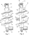
- FIGS. 1 or 2 are shown. Due to the largely same structure of the two augers 10 is a description directly with reference to both figures.
- the auger 10 has a tubular central shaft 14, which is arranged coaxially to a vertical axis 12.
- the term "vertical” refers to the usual arrangement of the auger 10 in operation, and in certain cases also deviations of the screw arrangement occur by a few degrees different from the vertical and are included.
- a pilot 16 is arranged as a centering tip.
- a connecting device 28 is arranged, which is designed in particular for connection to a Kelly bar.
- a removal device 18 which is constructed of a plurality of Abtragszähnen.
- soil material is removed during operation of the auger 10 and crushed.
- the abraded soil material is conveyed by the ablation device 18 in a rearward area onto a drill spiral 20 which helically extends around the tubular central shaft 18 to an upper end region.
- the drilling helix 20 is constructed in the illustrated schematic embodiment of three drill coils 24, each covering about a full circle.
- the drill bit 20 has a base coil 21, which has a perpendicular to the vertical axis 12 perpendicular or horizontal course in a conventional manner in vertical section.
- a first discharge element 30a is applied on the upper side and a second, smaller discharge element 30b is applied on its lower side.
- the diverting elements 30a, 30b are also helical, but face each other the vertical axis 12 a sharp discharge angle 38.
- the discharge angle 38 is the respective smaller angle, which is spanned by the vertical axis 12 and a discharge surface 32 of the discharge element 30 in vertical section.
- the discharge element 30b widens in the axial direction of the drill spiral 20.
- the obliquely arranged discharge elements 30a, 30b form an approximately wedge-shaped intermediate space 22 between the individual drill coils 24 which extends radially outwardly extended.
- a sliding coating by which the static friction is reduced.
- a sliding coating by which the static friction is reduced.
- a removal device of which in Fig. 2 only nozzle openings 42 are shown on the central shaft 14.
- a lubricating fluid such as a vegetable oil, can be sprayed onto the drilling helix 20 via a feed line (not shown) in the interior of the center shaft 14. The application can take place before and / or during drilling or emptying.
- the auger 10 is faster again after a drilling operation for a further drilling operation available. This can increase the machine usage. To shake off the soil material can also be rotated at a slower speed, which damage to the device can be avoided.
Description
Die Erfindung betrifft eine Bohrschnecke zum Erdbohren mit einem rohrförmigen und zu einer Vertikalachse koaxialen Mittenschaft und mit zumindest einer Bohrwendel aus einem Blech, wobei sich die Bohrwendel wendelförmig um den Mittenschaft erstreckt und daran befestigt, insbesondere angeschweißt ist, gemäß dem Oberbegriff des Anspruchs 1.The invention relates to a drilling auger for earth boring with a central shaft coaxial with a vertical axis and with at least one drill spiral made of a metal sheet, wherein the drill spiral extends helically around the center shaft and is fastened thereto, in particular welded, according to the preamble of claim 1.
Eine derartige Bohrschnecke wird insbesondere mit Bohrgeräten für den Spezialtiefbau eingesetzt, etwa um Gründungspfähle zu erstellen. Die Bohrschnecke wird mittels eines Bohrgerätes in den Erdboden ein- oder mehrmals abgebohrt, bis die gewünschte Tiefe erreicht ist. Am bodenseitigen Ende der Bohrschnecke ist eine Abtragseinrichtung angeordnet, durch welche anstehender Boden abgearbeitet und zerkleinert wird. Das abgetragene Bodenmaterial wird durch die Drehbewegung der angetriebenen Bohrschnecke von der Bohrwendel nach oben gefördert und darauf gelagert. Zur Stützung der Bohrlochwandung kann vorgesehen sein, dass auf den Bohrwendeln ausreichend abgetragenes Bodenmaterial verbleibt oder ein Stützrohr angeordnet ist.Such a drilling auger is used in particular with drilling equipment for special civil engineering, for example to create foundation piles. The auger is drilled in the ground one or more times by means of a drill until the desired depth is reached. At the bottom end of the auger a removal device is arranged, is processed by which pending soil and crushed. The excavated soil material is conveyed upwardly by the rotary movement of the driven auger from the drill spiral and stored thereon. To support the borehole wall, it may be provided that sufficiently removed soil material remains on the boring coils or a support tube is arranged.
Nach dem Herausziehen der Bohrschnecke aus dem Bohrloch sind die Windungen der Bohrwendeln noch mit Bodenmaterial gefüllt. Bei lockerem Bodenmaterial können die Windungen durch intermittierendes Drehen einfach entleert werden. Bei bindigen Böden, etwa bei Lehmböden, ist ein solches Entfernen des Bodenmaterials aus der Bohrschnecke kaum möglich.After removing the auger from the wellbore, the turns of the augers are still filled with soil material. With loosely ground material, the turns can simply be emptied by intermittent turning. In cohesive soils, such as loamy soils, such removal of the soil material from the auger is hardly possible.
Eine gattungsbildende Bohrschnecke ist aus der
Aus der
Eine weitere Reinigungsvorrichtung für eine Bohrschnecke mit einem mechanischen Abstreifen des Bodenmaterials ist aus der
Die Druckschrift
Die
Der Erfindung liegt die Aufgabe zugrunde, eine Bohrschnecke zum Erdbohren anzugeben, welche eine einfache Entleerung eines Zwischenraumes zwischen den Schneckenwindungen ermöglicht.The invention has for its object to provide a drilling auger for Erdbohren, which allows easy emptying of a gap between the screw turns.
Die Aufgabe wird durch eine Bohrschnecke mit den Merkmalen des Anspruchs 1 gelöst. Bevorzugte Ausführungsformen der Erfindung sind in den abhängigen Ansprüchen angegeben. Die erfindungsgemäße Bohrschnecke ist dadurch gekennzeichnet, dass zum radialen Ableiten von abgebohrtem Bodenmaterial an der Bohrwendel eine Ableitfläche vorgesehen ist, welche in einem Vertikalschnitt einen von 90° unterschiedlichen Ableitwinkel zur Vertikalachse aufweist.The object is achieved by a drilling auger with the features of claim 1. Preferred embodiments of the invention are indicated in the dependent claims. The auger according to the invention is characterized in that a discharge surface is provided for the radial discharge of drilled soil material on the drill spiral, which in a vertical section has a deviating angle of 90 ° to the vertical axis.
Ein Grundgedanke der Erfindung liegt darin, die Bohrwendeln radial schräg nach außen anzustellen, so dass das Bodenmaterial auf den Schneckenwendeln nach Austritt aus dem Bohrloch unter Schwerkrafteinwirkung leicht abgleiten kann. Bei einem spitzen Winkel der Schrägstellung oder des Ablenkwinkels zur Mitten- oder Vertikalachse der Bohrschnecke von unter 90°, insbesondere mit einem Winkel zwischen 30° und 80°, insbesondere zwischen 45° und 75°, wird ein leichtes Entleeren der Bohrwendel bevorzugterweise dann erreicht, wenn die Bohrschnecke intermittierend mit häufigem Drehrichtungswechsel gedreht wird. Ein Vertikalschnitt weist eine Schnittebene entlang der Mitten- oder Vertikalachse auf.A basic idea of the invention is to make the boring spirals radially obliquely outwards, so that the soil material on the screw flights can easily slide off after exiting the borehole under the action of gravity. At an acute angle of the skew or the deflection angle to the center or vertical axis of the auger of less than 90 °, in particular at an angle between 30 ° and 80 °, in particular between 45 ° and 75 °, a slight emptying of the drill bit is preferably then achieved when the auger is intermittent is rotated with frequent change of direction. A vertical section has a sectional plane along the center or vertical axis.
Es wurde festgestellt, dass selbst bei bestimmten bindigen Böden mit einer derartigen Ableitfläche ein hinreichendes Entleeren der Bohrwendel erreicht wird, ohne dass eine zusätzliche Reinigungseinrichtung benötigt oder deren Einsatz zumindest erheblich reduziert wird. Die Bohrschnecke kann insbesondere als ein sogenannter Schneckenbohrer mit einer typischen Länge bis zu 3m ausgebildet sein. Die Bohrschnecke kann aber auch länger oder kürzer und mit weiteren Arbeitselementen kombiniert sein.It has been found that even with certain cohesive soils with such a discharge surface sufficient drainage of the drill wire is achieved without the need for additional cleaning device or their use is at least significantly reduced. The auger may in particular be designed as a so-called auger with a typical length of up to 3 m. The auger may also be longer or shorter and combined with other working elements.
Eine bevorzugte Ausführungsform der Erfindung besteht darin, dass sich ein Zwischenraum, welcher zwischen zwei axial benachbarten Windungen der Bohrwendel umgrenzt ist, von der Vertikalachse radial nach außen hin aufweitet. Dieser Zwischenraum, auch Schneckengang genannt, weitet sich also keilartig oder konisch nach außen auf. Diese Aufweitung radial nach außen sorgt für ein besonders gutes Abgleiten des Bodenmaterials von der Bohrwendel.A preferred embodiment of the invention is that a gap, which is bounded between two axially adjacent turns of the drill spiral, widens radially outwardly from the vertical axis. This intermediate space, also called helical flight, thus widened in a wedge-shaped or conical manner to the outside. This expansion radially outwards ensures a particularly good sliding of the soil material from the drill spiral.
Nach der Erfindung ist vorgesehen, dass zum Bilden der Ableitfläche auf eine Bohrwendel mit einem rechtwinkligen Querschnittsverlauf ein Ableitelement aufgebracht ist. Auf diese Weise kann auch eine herkömmliche, bestehende Bohrwendel nachgerüstet werden. Das helixförmige Ableitelement kann dabei eine geringere Material- oder Blechdicke aufweisen als die Bohrwendel. Das Ableitelement kann aber auch ein massiver Kunststoffeinsatz sein, welcher segmentweise auf bestehende Bohrwindungen mit einer horizontalen Ausrichtung in Querschnittsrichtung aufgebracht wird.According to the invention it is provided that a discharge element is applied to form the discharge surface on a drill spiral having a rectangular cross-sectional profile. In this way, a conventional, existing drill spiral can be retrofitted. The helical discharge element can have a smaller material or sheet thickness than the drill spiral. The diverter can also be a solid plastic insert, which is applied in segments to existing drill coils with a horizontal orientation in the cross-sectional direction.
Fertigungstechnisch bevorzugt ist es, dass das Ableitelement aus einem Blech gebildet ist. Das Stahlblech wird insbesondere auf eine metallische Bohrwendel und einen metallischen Mittenschaft aufgeschweißt.In terms of manufacturing technology, it is preferred that the diverting element is formed from a metal sheet. The steel sheet is welded in particular to a metallic drill spiral and a metallic center shaft.
Eine weitere bevorzugte Ausgestaltung der Erfindung besteht darin, dass die Ableitfläche auf einer Oberseite, einer Unterseite oder der Ober- und der Unterseite der Bohrwendel angeordnet ist. Eine einfache Anordnung kann insbesondere darin bestehen, dass die Ableitfläche ausschließlich auf der Oberseite der Bohrwendel angeordnet ist. Somit ist also die Auflagefläche des Bodenmaterials auf der Bohrwendel radial nach außen schräg gestellt. In bestimmten Fällen kann aber auch lediglich eine Schrägstellung an der Unterseite der Bohrwendeln oder vorzugsweise an der Ober- und der Unterseite der Bohrwendel vorgesehen sein.A further preferred embodiment of the invention is that the discharge surface on a top, a bottom or the top and bottom of the Drill is arranged. A simple arrangement may consist in particular in that the discharge surface is arranged exclusively on the upper side of the drill spiral. Thus, therefore, the support surface of the soil material is placed on the drill spiral radially outward. In certain cases, however, only an oblique position may be provided on the underside of the drilling helices or preferably on the top and the bottom of the drill helix.
Grundsätzlich ist es nach der Erfindung vorgesehen, dass sich die Ableitfläche entlang der gesamten Bohrwendel erstreckt. Die Bohrwendel ist üblicherweise entlang des gesamten rohrförmigen Mittenschaftes angeordnet und erstreckt sich von einer Unterseite der Bohrschnecke, an welcher die Abtragseinrichtung und eine Zentrierspitze angeordnet sein kann, bis zum oberen Ende, an welcher eine Verbindungs- oder Halteeinrichtung zum Halten oder Antreiben der Schnecke vorgesehen ist. Zur Reduzierung des Herstellungsaufwandes ist es bevorzugt, dass die Ableitfläche nur in einem radialen und/oder axialen Teilbereich der Bohrwendel angeordnet ist. Insbesondere kann die Ableitfläche nur in einem radial inneren Bereich der Bohrwendel angeordnet sein.In principle, it is provided according to the invention that the discharge surface extends along the entire drill spiral. The drilling helix is usually arranged along the entire tubular central shaft and extends from an underside of the auger, on which the removal device and a centering tip can be arranged, to the upper end, to which a connecting or holding device for holding or driving the worm is provided , In order to reduce the manufacturing outlay, it is preferred that the discharge surface is arranged only in a radial and / or axial portion of the drill spiral. In particular, the discharge surface can be arranged only in a radially inner region of the drill spiral.
Eine weitere bevorzugte Ausführungsform der Erfindung besteht darin, dass die Ableitfläche im Querschnitt linear oder bogenförmig ausgebildet ist. Eine lineare Ausbildung ist aus fertigungstechnischer Sicht vorteilhaft, da diese aus einem helixförmig gebogenen Blech gefertigt werden kann. Mittels einer bogen- oder kurvenförmig gestalteten Ableitfläche kann ein Abgleiten oder Abrutschen des Bodenmateriales von der Bohrwendel weiter unterstützt werden.A further preferred embodiment of the invention is that the discharge surface is formed in cross-section linear or arcuate. A linear design is advantageous from a manufacturing point of view, since it can be made from a helically bent sheet metal. By means of a curved or curved Ableitfläche sliding or slipping of the soil material can be further supported by the Bohrwendel.
Grundsätzlich kann die Bohrwendel weitgehend einheitlich entlang der Bohrschnecke ausgebildet sein. Ein differenziertes Abgleitverhalten kann nach der Erfindung dadurch erreicht werden, dass sich der Ableitwinkel im axialen Verlauf der Bohrwendel ändert. So kann etwa der Ableitwinkel in einem oberen Bereich steiler oder flacher sein als in einem unteren Bereich der Bohrwendel.In principle, the drilling helix can be formed largely uniformly along the auger. A differentiated sliding behavior can be achieved according to the invention in that the deflection angle changes in the axial course of the drilling helix. For example, the lead angle may be steeper or shallower in an upper area than in a lower area of the drill bit.
Eine weitere Verbesserung der Bohrwendelentleerung wird nach einer Ausführungsvariante der Erfindung dadurch erzielt, dass die Bohrwendel mit der Ableitfläche mit einer Gleitbeschichtung versehen ist. Die Gleitbeschichtung kann eine Teflonbeschichtung oder eine andere vergleichbare Beschichtung, etwa eine Keramikbeschichtung, sein. Auch bei bindigen Böden kann so die Haftreibung zwischen dem Bodenmaterial und der Bohrwendel reduziert werden, was ein leichteres Abrutschen ermöglicht. Die Gleitbeschichtung kann grundsätzlich auch an dem Mittenschaft angeordnet sein.A further improvement of Bohrwendelentleerung is achieved according to a variant of the invention in that the drill spiral is provided with the discharge surface with a sliding coating. The slip coating may be a Teflon coating or other comparable coating, such as a ceramic coating, his. Even with cohesive soils, the static friction between the soil material and the drill spiral can be reduced, which allows easier slipping. The sliding coating can in principle also be arranged on the center shaft.
Neben einer dauerhaften Gleitbeschichtung kann eine temporäre Gleitbeschichtung, etwa aus einem Flüssigkeitsfilm, etwa einem Ölfilm, vorgesehen werden. Die Gleitbeschichtung kann aus biologisch abbaubaren Schmierölen, insbesondere auf Pflanzenbasis, bestehen. Hierzu gibt es eine Ausführungsform der Erfindung, in der eine Auftragseinrichtung vorgesehen ist, mit welcher die Gleitbeschichtung auf die Bohrwendel aufragbar ist. Die Auftragseinrichtung kann insbesondere eine Sprüh- oder Düseneinrichtung sein, welche entlang der Bohrwendel an verschiedenen Stellen angeordnet ist.In addition to a durable lubricating coating, a temporary lubricating coating, such as a liquid film, such as an oil film, can be provided. The lubricious coating may consist of biodegradable lubricating oils, especially plant based. For this purpose, there is an embodiment of the invention in which an application device is provided, with which the sliding coating can be applied to the drilling helix. In particular, the application device may be a spray or nozzle device which is arranged at different locations along the drill spiral.
Besonders bevorzugt ist es nach der Erfindung, dass die Auftragseinrichtung mindestens eine Düsenöffnung aufweist, welche mit einer Zuführleitung verbunden ist. Insbesondere können mehrere Düsenöffnungen an vorgesehenen Stellen der Bohrwendel angeordnet sein, welche etwa über eine gemeinsame Zuführleitung im Innenraum des rohrförmigen Mittenschaftes miteinander verbunden sind.According to the invention, it is particularly preferred that the application device has at least one nozzle opening which is connected to a supply line. In particular, a plurality of nozzle openings may be arranged at intended locations of the drill spiral, which are connected to one another via a common supply line in the interior of the tubular central shaft.
Die Erfindung betrifft weiterhin ein Bohrgerät zum Erdbohren mit einem im Wesentlichen vertikalen Mast, entlang welchem eine Bohrschnecke verfahrbar und drehend antreibbar angeordnet ist. Ein derartiges Bohrgerät, wie es etwa aus der eingangs genannten
Die Erfindung wird nachfolgend anhand von bevorzugten Ausführungsbeispielen weiter beschrieben, welche schematisch in den beigefügten Zeichnungen dargestellt sind. In der Zeichnung zeigen:
- Fig. 1
- eine Seitenansicht einer erfindungsgemäßen Bohrschnecke und
- Fig. 2
- eine Seitenansicht einer weiteren Bohrschnecke ähnlich zu der von
Fig. 1 mit einem teilweisen Vertikalschnitt.
- Fig. 1
- a side view of a drilling screw according to the invention and
- Fig. 2
- a side view of another auger similar to that of
Fig. 1 with a partial vertical section.
Die Erfindung wird nachfolgend anhand von zwei Ausführungsbeispielen einer erfindungsgemäßen Bohrschnecke 10 näher beschrieben, welche schematisch in den
Die erfindungsgemäße Bohrschnecke 10 weist einen rohrförmigen Mittenschaft 14 auf, welcher koaxial zu einer Vertikalachse 12 angeordnet ist. Der Begriff "vertikal" bezieht sich auf die übliche Anordnung der Bohrschnecke 10 im Betrieb, wobei in bestimmten Fällen auch Abweichungen der Schneckenanordnung um einige Grad abweichend von der Vertikalen auftreten und mitumfasst sind. Am unteren Ende des rohrförmigen Mittenschaftes 14 ist ein Pilot 16 als Zentrierspitze angeordnet. Am oberen Ende ist eine Verbindungseinrichtung 28 angeordnet, welche insbesondere zur Verbindung mit einer Kellystange ausgebildet ist.The
Am unteren Ende des Mittenschaftes 14 erstreckt sich in radialer Richtung eine Abtragseinrichtung 18, welche aus mehreren Abtragszähnen aufgebaut ist. Durch die Abtragseinrichtung 18 wird Bodenmaterial beim Betrieb der Bohrschnecke 10 abgetragen und zerkleinert. Das abgetragene Bodenmaterial wird von der Abtragseinrichtung 18 in einen rückwärtigen Bereich auf eine Bohrwendel 20 gefördert, welche sich helixförmig um den rohrförmigen Mittenschaft 18 bis zu einem oberen Endbereich erstreckt.At the lower end of the
Die Bohrwendel 20 ist in der dargestellten schematischen Ausführungsform aus drei Bohrwindungen 24 aufgebaut, welche jeweils etwa einen Vollkreis abdecken. Wie insbesondere aus der Teilschnittdarstellung von
Wie insbesondere im Verlauf des unteren Ableitelementes 30b zu ersehen ist, verbreitert sich das Ableitelement 30b im axialen Verlauf der Bohrwendel 20. Durch die schräg gestellten Ableitelemente 30a, 30b wird zwischen den einzelnen Bohrwendeln 24 ein etwa keilförmiger Zwischenraum 22 ausgebildet, welcher sich radial nach außen hin erweitert. Durch diesen keilförmigen, sich erweiternden Zwischenraum 22 und der schräg gestellten Ableitfläche 32 des oberen Ableitelementes 30a wird ein leichteres Abrutschen des abgetragenen Bodenmateriales von der Bohrwendel 20 erreicht, wenn die Bohrschnecke 10 aus dem Bohrloch herausgezogen ist. Dies erlaubt auch bei bindigen Böden eine gute Entleerung der Bohrwendel 20 der Bohrschnecke 10 durch intermittierendes, also schnell wechselndes Drehen der Bohrschnecke 10.As can be seen in particular in the course of the
Zur Verbesserung der Entleerung kann auf die Ableitfläche 32 zumindest des oberen Ableitelementes 30a eine Gleitbeschichtung aufgebracht sein, durch welche die Haftreibung reduziert ist. Im Ausführungsbeispiel nach
Durch die einfachere und damit schnellere Entleerung der Bohrwendel 24 steht die Bohrschnecke 10 nach einem Bohrvorgang wieder schneller für einen weiteren Bohrvorgang zur Verfügung. Damit kann die Maschinennutzung erhöht werden. Zum Abschütteln des Bodenmaterials kann auch mit geringerer Geschwindigkeit gedreht werden, wodurch Beschädigungen am Gerät vermieden werden können.Due to the easier and thus faster emptying of the
Claims (12)
- Auger for soil drilling with a central shaft (14) which is tubular and coaxial to a vertical axis (12) and with at least one drill flight (20) made of a sheet metal, wherein the drill flight (20) extends helically around the central shaft (14) and is fixed thereon, and on the drill flight (20) a discharge element (30) having a rectangular cross-sectional course is arranged in order to form a discharge surface (32),
wherein for the radial discharge of drilled soil material the discharge surface (32) is positioned in a radially outward inclined manner on the drill flight (20) and, in a vertical section, has a discharge angle (38) that differs from 90° with respect to the vertical axis (12),
characterized in that
the discharge surface (32) is arranged in a radially internal portion of the drill flight (20). - Auger according to claim 1,
characterized in that
the drill flight is welded to the central shaft (14). - Auger according to claim 1 or 2,
characterized in that
a space (22) which is defined between two axially adjacent turns (24) of the drill flight (20) widens radially outwards from the vertical axis (12). - Auger according to claim 3,
characterized in that
the discharge element (30) is formed of a sheet metal. - Auger according to any one of claims 1 to 4,
characterized in that
the discharge surface (32) is arranged on an upper side, an underside or on the upper side and the underside of the drill flight (32). - Auger according to any one of claims 1 to 5,
characterized in that
the discharge surface (32) is only arranged in an axial portion of the drill flight (20). - Auger according to any one of claims 1 to 6,
characterized in that
the discharge surface (32) is designed in a linear or arched manner in cross-section. - Auger according to any one of claims 1 to 7,
characterized in that
the discharge angle (38) changes in the axial course of the drill flight (20). - Auger according to any one of claims 1 to 6,
characterized in that
the drill flight (20) with the discharge surface (32) is provided with a slide coating. - Auger according to claim 9,
characterized in that
an application means is provided, with which the slide coating can be applied onto the drill flight (20). - Auger according to claim 10,
characterized in that
the application means has at least one nozzle opening (42) which is connected to a supply line. - Drilling apparatus for soil drilling
with a substantially vertical mast, along which an auger (10) can be moved and driven in a rotating manner,
characterized in that
an auger (10) according to any one of claims 1 to 11 is provided.
Priority Applications (2)
| Application Number | Priority Date | Filing Date | Title |
|---|---|---|---|
| EP13193903.5A EP2876246B1 (en) | 2013-11-21 | 2013-11-21 | Auger drive for drilling into soil |
| CN201410670151.8A CN104653110B (en) | 2013-11-21 | 2014-11-21 | For the auger of soil drilling |
Applications Claiming Priority (1)
| Application Number | Priority Date | Filing Date | Title |
|---|---|---|---|
| EP13193903.5A EP2876246B1 (en) | 2013-11-21 | 2013-11-21 | Auger drive for drilling into soil |
Publications (2)
| Publication Number | Publication Date |
|---|---|
| EP2876246A1 EP2876246A1 (en) | 2015-05-27 |
| EP2876246B1 true EP2876246B1 (en) | 2019-05-01 |
Family
ID=49641601
Family Applications (1)
| Application Number | Title | Priority Date | Filing Date |
|---|---|---|---|
| EP13193903.5A Active EP2876246B1 (en) | 2013-11-21 | 2013-11-21 | Auger drive for drilling into soil |
Country Status (2)
| Country | Link |
|---|---|
| EP (1) | EP2876246B1 (en) |
| CN (1) | CN104653110B (en) |
Families Citing this family (4)
| Publication number | Priority date | Publication date | Assignee | Title |
|---|---|---|---|---|
| EP3361040B1 (en) * | 2017-02-13 | 2019-11-27 | BAUER Maschinen GmbH | Soil processing tool and method for creating a hole in the soil |
| CN106869775B (en) * | 2017-03-08 | 2018-11-27 | 杭州富阳飞尚装饰工程有限公司 | A kind of arc ground pile auger of municipal administration pile foundation engineering |
| CN111980593B (en) * | 2020-09-10 | 2022-05-17 | 贵州财经大学 | Drilling device for oil exploitation |
| CN113250610B (en) * | 2021-06-07 | 2022-11-08 | 山东科技大学 | Spiral propelling type underground exploration trolley |
Citations (1)
| Publication number | Priority date | Publication date | Assignee | Title |
|---|---|---|---|---|
| US2981403A (en) * | 1957-04-15 | 1961-04-25 | Joy Mfg Co | Conveying apparatus |
Family Cites Families (8)
| Publication number | Priority date | Publication date | Assignee | Title |
|---|---|---|---|---|
| DE2059232B1 (en) * | 1970-12-02 | 1972-03-09 | Werkzeugbau Gmbh | Rock drill |
| DE8437600U1 (en) | 1984-12-21 | 1988-09-08 | Bauer Spezialtiefbau Gmbh, 8898 Schrobenhausen, De | |
| DE3446900C2 (en) | 1984-12-21 | 1986-10-23 | Karl Bauer Spezialtiefbau GmbH & Co KG, 8898 Schrobenhausen | Method and device for cleaning the helix of an auger |
| CN1078519A (en) * | 1992-05-12 | 1993-11-17 | 王英权 | Pile-making method by drilling-slurry and drilling tool rotary spray apparatus |
| GB9719254D0 (en) * | 1997-09-11 | 1997-11-12 | Limited | Earthworking equipment |
| US6321861B1 (en) * | 1999-06-15 | 2001-11-27 | Henry S. Leichter | Auger |
| ITUD20020117A1 (en) | 2002-05-30 | 2003-12-01 | Casagrande Spa | CLEANING DEVICE FOR PROPELLER TOOLS AND CLEANING PROCEDURE OF A PROPELLER TOOL ADOPTING SUCH DEVICE |
| EP1895090B1 (en) * | 2006-08-23 | 2008-10-15 | BAUER Maschinen GmbH | Method and apparatus for creating a borehole in the ground |
-
2013
- 2013-11-21 EP EP13193903.5A patent/EP2876246B1/en active Active
-
2014
- 2014-11-21 CN CN201410670151.8A patent/CN104653110B/en active Active
Patent Citations (1)
| Publication number | Priority date | Publication date | Assignee | Title |
|---|---|---|---|---|
| US2981403A (en) * | 1957-04-15 | 1961-04-25 | Joy Mfg Co | Conveying apparatus |
Also Published As
| Publication number | Publication date |
|---|---|
| CN104653110A (en) | 2015-05-27 |
| EP2876246A1 (en) | 2015-05-27 |
| CN104653110B (en) | 2017-06-20 |
Similar Documents
| Publication | Publication Date | Title |
|---|---|---|
| EP1895090B1 (en) | Method and apparatus for creating a borehole in the ground | |
| EP2562310B1 (en) | Submarine drilling assembly and method for producing a borehole in a sea floor | |
| EP2876246B1 (en) | Auger drive for drilling into soil | |
| EP2133507B1 (en) | Drilling device and drilling method | |
| EP0355379A2 (en) | Drilling-injection anchor | |
| EP2863003A2 (en) | Expanding tool and device for expanding a passage in the ground | |
| EP0855489B1 (en) | Earth displacement drill | |
| EP2770156A1 (en) | Drilling tool and method for drilling in soil | |
| DE3446902A1 (en) | Device for discharging cuttings from the auger of an auger drilling appliance for earth bores | |
| EP1491716A2 (en) | Method for drilling a borehole and wet boring tool | |
| EP2011958B1 (en) | Auger | |
| EP1905945A1 (en) | Auger for drilling an earth borehole | |
| EP0837190A2 (en) | Process and device for the controlled in-ground realisation of piles and bulkheads | |
| DE3423789C2 (en) | Drilling device for rock drilling | |
| EP2666911B1 (en) | Method for producing a floor mortar wall in the floor | |
| DE4107834A1 (en) | Hollow displacement auger - has drive shaft extending longitudinally through its centre, with pointed tip, and has anti-buckling discs fitted at intervals along drive shaft, requiring minimum torque for control | |
| EP3361040B1 (en) | Soil processing tool and method for creating a hole in the soil | |
| DE202015102848U1 (en) | Core drilling tool for rock drilling | |
| DE19651586C2 (en) | Drilling device for partial displacement piles | |
| EP1580323B1 (en) | Auger and method of installing piles in a ground by means of said auger | |
| DE2657751B1 (en) | Overlay drill rods | |
| DE3513194C1 (en) | Apparatus for penetrating soil strata near the surface | |
| DE102004062129B4 (en) | Tunneling machine for horizontal propulsion of underground pipe tunnels | |
| EP3067512B1 (en) | Rotary drilling tool, drilling device and method for creating a borehole in the ground | |
| DE2845316C2 (en) | Apparatus for producing a borehole for a casing string which can be pressed into the borehole |
Legal Events
| Date | Code | Title | Description |
|---|---|---|---|
| PUAI | Public reference made under article 153(3) epc to a published international application that has entered the european phase |
Free format text: ORIGINAL CODE: 0009012 |
|
| 17P | Request for examination filed |
Effective date: 20131121 |
|
| AK | Designated contracting states |
Kind code of ref document: A1 Designated state(s): AL AT BE BG CH CY CZ DE DK EE ES FI FR GB GR HR HU IE IS IT LI LT LU LV MC MK MT NL NO PL PT RO RS SE SI SK SM TR |
|
| AX | Request for extension of the european patent |
Extension state: BA ME |
|
| R17P | Request for examination filed (corrected) |
Effective date: 20150708 |
|
| RBV | Designated contracting states (corrected) |
Designated state(s): AL AT BE BG CH CY CZ DE DK EE ES FI FR GB GR HR HU IE IS IT LI LT LU LV MC MK MT NL NO PL PT RO RS SE SI SK SM TR |
|
| STAA | Information on the status of an ep patent application or granted ep patent |
Free format text: STATUS: EXAMINATION IS IN PROGRESS |
|
| 17Q | First examination report despatched |
Effective date: 20170824 |
|
| GRAP | Despatch of communication of intention to grant a patent |
Free format text: ORIGINAL CODE: EPIDOSNIGR1 |
|
| STAA | Information on the status of an ep patent application or granted ep patent |
Free format text: STATUS: GRANT OF PATENT IS INTENDED |
|
| INTG | Intention to grant announced |
Effective date: 20181205 |
|
| GRAS | Grant fee paid |
Free format text: ORIGINAL CODE: EPIDOSNIGR3 |
|
| GRAA | (expected) grant |
Free format text: ORIGINAL CODE: 0009210 |
|
| STAA | Information on the status of an ep patent application or granted ep patent |
Free format text: STATUS: THE PATENT HAS BEEN GRANTED |
|
| AK | Designated contracting states |
Kind code of ref document: B1 Designated state(s): AL AT BE BG CH CY CZ DE DK EE ES FI FR GB GR HR HU IE IS IT LI LT LU LV MC MK MT NL NO PL PT RO RS SE SI SK SM TR |
|
| REG | Reference to a national code |
Ref country code: GB Ref legal event code: FG4D Free format text: NOT ENGLISH |
|
| REG | Reference to a national code |
Ref country code: CH Ref legal event code: EP Ref country code: AT Ref legal event code: REF Ref document number: 1127116 Country of ref document: AT Kind code of ref document: T Effective date: 20190515 |
|
| REG | Reference to a national code |
Ref country code: DE Ref legal event code: R096 Ref document number: 502013012741 Country of ref document: DE |
|
| REG | Reference to a national code |
Ref country code: IE Ref legal event code: FG4D Free format text: LANGUAGE OF EP DOCUMENT: GERMAN |
|
| REG | Reference to a national code |
Ref country code: NL Ref legal event code: MP Effective date: 20190501 |
|
| REG | Reference to a national code |
Ref country code: LT Ref legal event code: MG4D |
|
| PG25 | Lapsed in a contracting state [announced via postgrant information from national office to epo] |
Ref country code: NO Free format text: LAPSE BECAUSE OF FAILURE TO SUBMIT A TRANSLATION OF THE DESCRIPTION OR TO PAY THE FEE WITHIN THE PRESCRIBED TIME-LIMIT Effective date: 20190801 Ref country code: HR Free format text: LAPSE BECAUSE OF FAILURE TO SUBMIT A TRANSLATION OF THE DESCRIPTION OR TO PAY THE FEE WITHIN THE PRESCRIBED TIME-LIMIT Effective date: 20190501 Ref country code: NL Free format text: LAPSE BECAUSE OF FAILURE TO SUBMIT A TRANSLATION OF THE DESCRIPTION OR TO PAY THE FEE WITHIN THE PRESCRIBED TIME-LIMIT Effective date: 20190501 Ref country code: LT Free format text: LAPSE BECAUSE OF FAILURE TO SUBMIT A TRANSLATION OF THE DESCRIPTION OR TO PAY THE FEE WITHIN THE PRESCRIBED TIME-LIMIT Effective date: 20190501 Ref country code: ES Free format text: LAPSE BECAUSE OF FAILURE TO SUBMIT A TRANSLATION OF THE DESCRIPTION OR TO PAY THE FEE WITHIN THE PRESCRIBED TIME-LIMIT Effective date: 20190501 Ref country code: AL Free format text: LAPSE BECAUSE OF FAILURE TO SUBMIT A TRANSLATION OF THE DESCRIPTION OR TO PAY THE FEE WITHIN THE PRESCRIBED TIME-LIMIT Effective date: 20190501 Ref country code: PT Free format text: LAPSE BECAUSE OF FAILURE TO SUBMIT A TRANSLATION OF THE DESCRIPTION OR TO PAY THE FEE WITHIN THE PRESCRIBED TIME-LIMIT Effective date: 20190901 Ref country code: SE Free format text: LAPSE BECAUSE OF FAILURE TO SUBMIT A TRANSLATION OF THE DESCRIPTION OR TO PAY THE FEE WITHIN THE PRESCRIBED TIME-LIMIT Effective date: 20190501 Ref country code: FI Free format text: LAPSE BECAUSE OF FAILURE TO SUBMIT A TRANSLATION OF THE DESCRIPTION OR TO PAY THE FEE WITHIN THE PRESCRIBED TIME-LIMIT Effective date: 20190501 |
|
| PG25 | Lapsed in a contracting state [announced via postgrant information from national office to epo] |
Ref country code: BG Free format text: LAPSE BECAUSE OF FAILURE TO SUBMIT A TRANSLATION OF THE DESCRIPTION OR TO PAY THE FEE WITHIN THE PRESCRIBED TIME-LIMIT Effective date: 20190801 Ref country code: GR Free format text: LAPSE BECAUSE OF FAILURE TO SUBMIT A TRANSLATION OF THE DESCRIPTION OR TO PAY THE FEE WITHIN THE PRESCRIBED TIME-LIMIT Effective date: 20190802 Ref country code: LV Free format text: LAPSE BECAUSE OF FAILURE TO SUBMIT A TRANSLATION OF THE DESCRIPTION OR TO PAY THE FEE WITHIN THE PRESCRIBED TIME-LIMIT Effective date: 20190501 Ref country code: RS Free format text: LAPSE BECAUSE OF FAILURE TO SUBMIT A TRANSLATION OF THE DESCRIPTION OR TO PAY THE FEE WITHIN THE PRESCRIBED TIME-LIMIT Effective date: 20190501 |
|
| PG25 | Lapsed in a contracting state [announced via postgrant information from national office to epo] |
Ref country code: IS Free format text: LAPSE BECAUSE OF FAILURE TO SUBMIT A TRANSLATION OF THE DESCRIPTION OR TO PAY THE FEE WITHIN THE PRESCRIBED TIME-LIMIT Effective date: 20190901 |
|
| PG25 | Lapsed in a contracting state [announced via postgrant information from national office to epo] |
Ref country code: RO Free format text: LAPSE BECAUSE OF FAILURE TO SUBMIT A TRANSLATION OF THE DESCRIPTION OR TO PAY THE FEE WITHIN THE PRESCRIBED TIME-LIMIT Effective date: 20190501 Ref country code: SK Free format text: LAPSE BECAUSE OF FAILURE TO SUBMIT A TRANSLATION OF THE DESCRIPTION OR TO PAY THE FEE WITHIN THE PRESCRIBED TIME-LIMIT Effective date: 20190501 Ref country code: CZ Free format text: LAPSE BECAUSE OF FAILURE TO SUBMIT A TRANSLATION OF THE DESCRIPTION OR TO PAY THE FEE WITHIN THE PRESCRIBED TIME-LIMIT Effective date: 20190501 Ref country code: DK Free format text: LAPSE BECAUSE OF FAILURE TO SUBMIT A TRANSLATION OF THE DESCRIPTION OR TO PAY THE FEE WITHIN THE PRESCRIBED TIME-LIMIT Effective date: 20190501 Ref country code: EE Free format text: LAPSE BECAUSE OF FAILURE TO SUBMIT A TRANSLATION OF THE DESCRIPTION OR TO PAY THE FEE WITHIN THE PRESCRIBED TIME-LIMIT Effective date: 20190501 |
|
| REG | Reference to a national code |
Ref country code: DE Ref legal event code: R097 Ref document number: 502013012741 Country of ref document: DE |
|
| PG25 | Lapsed in a contracting state [announced via postgrant information from national office to epo] |
Ref country code: SM Free format text: LAPSE BECAUSE OF FAILURE TO SUBMIT A TRANSLATION OF THE DESCRIPTION OR TO PAY THE FEE WITHIN THE PRESCRIBED TIME-LIMIT Effective date: 20190501 |
|
| PLBE | No opposition filed within time limit |
Free format text: ORIGINAL CODE: 0009261 |
|
| STAA | Information on the status of an ep patent application or granted ep patent |
Free format text: STATUS: NO OPPOSITION FILED WITHIN TIME LIMIT |
|
| PG25 | Lapsed in a contracting state [announced via postgrant information from national office to epo] |
Ref country code: TR Free format text: LAPSE BECAUSE OF FAILURE TO SUBMIT A TRANSLATION OF THE DESCRIPTION OR TO PAY THE FEE WITHIN THE PRESCRIBED TIME-LIMIT Effective date: 20190501 |
|
| 26N | No opposition filed |
Effective date: 20200204 |
|
| PG25 | Lapsed in a contracting state [announced via postgrant information from national office to epo] |
Ref country code: PL Free format text: LAPSE BECAUSE OF FAILURE TO SUBMIT A TRANSLATION OF THE DESCRIPTION OR TO PAY THE FEE WITHIN THE PRESCRIBED TIME-LIMIT Effective date: 20190501 |
|
| PG25 | Lapsed in a contracting state [announced via postgrant information from national office to epo] |
Ref country code: SI Free format text: LAPSE BECAUSE OF FAILURE TO SUBMIT A TRANSLATION OF THE DESCRIPTION OR TO PAY THE FEE WITHIN THE PRESCRIBED TIME-LIMIT Effective date: 20190501 |
|
| REG | Reference to a national code |
Ref country code: CH Ref legal event code: PL |
|
| PG25 | Lapsed in a contracting state [announced via postgrant information from national office to epo] |
Ref country code: MC Free format text: LAPSE BECAUSE OF FAILURE TO SUBMIT A TRANSLATION OF THE DESCRIPTION OR TO PAY THE FEE WITHIN THE PRESCRIBED TIME-LIMIT Effective date: 20190501 Ref country code: CH Free format text: LAPSE BECAUSE OF NON-PAYMENT OF DUE FEES Effective date: 20191130 Ref country code: LI Free format text: LAPSE BECAUSE OF NON-PAYMENT OF DUE FEES Effective date: 20191130 Ref country code: LU Free format text: LAPSE BECAUSE OF NON-PAYMENT OF DUE FEES Effective date: 20191121 |
|
| REG | Reference to a national code |
Ref country code: BE Ref legal event code: MM Effective date: 20191130 |
|
| PG25 | Lapsed in a contracting state [announced via postgrant information from national office to epo] |
Ref country code: FR Free format text: LAPSE BECAUSE OF NON-PAYMENT OF DUE FEES Effective date: 20191130 Ref country code: IE Free format text: LAPSE BECAUSE OF NON-PAYMENT OF DUE FEES Effective date: 20191121 |
|
| PG25 | Lapsed in a contracting state [announced via postgrant information from national office to epo] |
Ref country code: BE Free format text: LAPSE BECAUSE OF NON-PAYMENT OF DUE FEES Effective date: 20191130 |
|
| REG | Reference to a national code |
Ref country code: AT Ref legal event code: MM01 Ref document number: 1127116 Country of ref document: AT Kind code of ref document: T Effective date: 20191121 |
|
| PG25 | Lapsed in a contracting state [announced via postgrant information from national office to epo] |
Ref country code: AT Free format text: LAPSE BECAUSE OF NON-PAYMENT OF DUE FEES Effective date: 20191121 |
|
| PG25 | Lapsed in a contracting state [announced via postgrant information from national office to epo] |
Ref country code: CY Free format text: LAPSE BECAUSE OF FAILURE TO SUBMIT A TRANSLATION OF THE DESCRIPTION OR TO PAY THE FEE WITHIN THE PRESCRIBED TIME-LIMIT Effective date: 20190501 |
|
| PG25 | Lapsed in a contracting state [announced via postgrant information from national office to epo] |
Ref country code: MT Free format text: LAPSE BECAUSE OF FAILURE TO SUBMIT A TRANSLATION OF THE DESCRIPTION OR TO PAY THE FEE WITHIN THE PRESCRIBED TIME-LIMIT Effective date: 20190501 Ref country code: HU Free format text: LAPSE BECAUSE OF FAILURE TO SUBMIT A TRANSLATION OF THE DESCRIPTION OR TO PAY THE FEE WITHIN THE PRESCRIBED TIME-LIMIT; INVALID AB INITIO Effective date: 20131121 |
|
| PG25 | Lapsed in a contracting state [announced via postgrant information from national office to epo] |
Ref country code: MK Free format text: LAPSE BECAUSE OF FAILURE TO SUBMIT A TRANSLATION OF THE DESCRIPTION OR TO PAY THE FEE WITHIN THE PRESCRIBED TIME-LIMIT Effective date: 20190501 |
|
| PGFP | Annual fee paid to national office [announced via postgrant information from national office to epo] |
Ref country code: GB Payment date: 20231107 Year of fee payment: 11 |
|
| PGFP | Annual fee paid to national office [announced via postgrant information from national office to epo] |
Ref country code: IT Payment date: 20231115 Year of fee payment: 11 Ref country code: DE Payment date: 20231107 Year of fee payment: 11 |