EP2876238A1 - Receiving element for a steel door frame and steel door frame with the same - Google Patents
Receiving element for a steel door frame and steel door frame with the same Download PDFInfo
- Publication number
- EP2876238A1 EP2876238A1 EP14190287.4A EP14190287A EP2876238A1 EP 2876238 A1 EP2876238 A1 EP 2876238A1 EP 14190287 A EP14190287 A EP 14190287A EP 2876238 A1 EP2876238 A1 EP 2876238A1
- Authority
- EP
- European Patent Office
- Prior art keywords
- receiving element
- leg
- element according
- steel frame
- carrier
- Prior art date
- Legal status (The legal status is an assumption and is not a legal conclusion. Google has not performed a legal analysis and makes no representation as to the accuracy of the status listed.)
- Granted
Links
- 229910000831 Steel Inorganic materials 0.000 title claims abstract description 32
- 239000010959 steel Substances 0.000 title claims abstract description 32
- 210000001364 upper extremity Anatomy 0.000 claims abstract description 17
- 238000003780 insertion Methods 0.000 claims abstract description 7
- 230000037431 insertion Effects 0.000 claims abstract description 7
- 210000003414 extremity Anatomy 0.000 claims abstract description 5
- 239000002184 metal Substances 0.000 claims description 7
- 238000003466 welding Methods 0.000 claims description 5
- 210000002105 tongue Anatomy 0.000 description 7
- 238000004519 manufacturing process Methods 0.000 description 3
- 238000005452 bending Methods 0.000 description 2
- 238000009434 installation Methods 0.000 description 2
- 239000000463 material Substances 0.000 description 2
- 238000000034 method Methods 0.000 description 2
- 238000003860 storage Methods 0.000 description 2
- 230000000052 comparative effect Effects 0.000 description 1
- 238000005520 cutting process Methods 0.000 description 1
- 230000003993 interaction Effects 0.000 description 1
- 230000013011 mating Effects 0.000 description 1
- 230000000630 rising effect Effects 0.000 description 1
- 230000006641 stabilisation Effects 0.000 description 1
- 238000011105 stabilization Methods 0.000 description 1
- 230000000087 stabilizing effect Effects 0.000 description 1
Images

Classifications
-
- E—FIXED CONSTRUCTIONS
- E05—LOCKS; KEYS; WINDOW OR DOOR FITTINGS; SAFES
- E05D—HINGES OR SUSPENSION DEVICES FOR DOORS, WINDOWS OR WINGS
- E05D7/00—Hinges or pivots of special construction
- E05D7/04—Hinges adjustable relative to the wing or the frame
- E05D7/0415—Hinges adjustable relative to the wing or the frame with adjusting drive means
- E05D7/0423—Screw-and-nut mechanisms
-
- E—FIXED CONSTRUCTIONS
- E05—LOCKS; KEYS; WINDOW OR DOOR FITTINGS; SAFES
- E05D—HINGES OR SUSPENSION DEVICES FOR DOORS, WINDOWS OR WINGS
- E05D11/00—Additional features or accessories of hinges
-
- E—FIXED CONSTRUCTIONS
- E05—LOCKS; KEYS; WINDOW OR DOOR FITTINGS; SAFES
- E05D—HINGES OR SUSPENSION DEVICES FOR DOORS, WINDOWS OR WINGS
- E05D15/00—Suspension arrangements for wings
-
- E—FIXED CONSTRUCTIONS
- E05—LOCKS; KEYS; WINDOW OR DOOR FITTINGS; SAFES
- E05D—HINGES OR SUSPENSION DEVICES FOR DOORS, WINDOWS OR WINGS
- E05D7/00—Hinges or pivots of special construction
- E05D7/04—Hinges adjustable relative to the wing or the frame
-
- E—FIXED CONSTRUCTIONS
- E06—DOORS, WINDOWS, SHUTTERS, OR ROLLER BLINDS IN GENERAL; LADDERS
- E06B—FIXED OR MOVABLE CLOSURES FOR OPENINGS IN BUILDINGS, VEHICLES, FENCES OR LIKE ENCLOSURES IN GENERAL, e.g. DOORS, WINDOWS, BLINDS, GATES
- E06B1/00—Border constructions of openings in walls, floors, or ceilings; Frames to be rigidly mounted in such openings
- E06B1/04—Frames for doors, windows, or the like to be fixed in openings
- E06B1/12—Metal frames
-
- E—FIXED CONSTRUCTIONS
- E06—DOORS, WINDOWS, SHUTTERS, OR ROLLER BLINDS IN GENERAL; LADDERS
- E06B—FIXED OR MOVABLE CLOSURES FOR OPENINGS IN BUILDINGS, VEHICLES, FENCES OR LIKE ENCLOSURES IN GENERAL, e.g. DOORS, WINDOWS, BLINDS, GATES
- E06B1/00—Border constructions of openings in walls, floors, or ceilings; Frames to be rigidly mounted in such openings
- E06B1/04—Frames for doors, windows, or the like to be fixed in openings
- E06B1/52—Frames specially adapted for doors
-
- E—FIXED CONSTRUCTIONS
- E05—LOCKS; KEYS; WINDOW OR DOOR FITTINGS; SAFES
- E05D—HINGES OR SUSPENSION DEVICES FOR DOORS, WINDOWS OR WINGS
- E05D7/00—Hinges or pivots of special construction
- E05D7/04—Hinges adjustable relative to the wing or the frame
- E05D2007/0476—Pocket hinges
-
- E—FIXED CONSTRUCTIONS
- E05—LOCKS; KEYS; WINDOW OR DOOR FITTINGS; SAFES
- E05Y—INDEXING SCHEME RELATING TO HINGES OR OTHER SUSPENSION DEVICES FOR DOORS, WINDOWS OR WINGS AND DEVICES FOR MOVING WINGS INTO OPEN OR CLOSED POSITION, CHECKS FOR WINGS AND WING FITTINGS NOT OTHERWISE PROVIDED FOR, CONCERNED WITH THE FUNCTIONING OF THE WING
- E05Y2600/00—Mounting or coupling arrangements for elements provided for in this subclass
- E05Y2600/50—Mounting methods; Positioning
- E05Y2600/52—Toolless
- E05Y2600/53—Snapping
Definitions
- the invention relates to a receiving element for a steel frame for receiving a door hinge with a carrier.
- the carrier has a two side legs and a connecting leg connecting the two side legs existing U-shaped portion and two adjoining each side leg mounting flanges.
- To the receiving element also includes a counterpart, which encloses a receiving space with the carrier and having a connecting leg opposite cover plate.
- a fastening device for fixing an inserted into the receiving space hinge strap of a door hinge is arranged, which is supported on the connecting leg and the cover plate.
- cover plate From the cover plate are two bearing limbs, which abut with their outer surfaces on the inside of the inner sides of the side legs and wherein the front of the cover plate is followed by a front leg with a recess for insertion of the hinge strap in the receiving space.
- Such a receiving element is made DE 199 30 448 A1 and is manufactured and sold by the applicant, for example under the type designation Variant VX7611 3D. It is fastened on the inside in a steel frame with the mounting flanges, so that the cover plate rests on the inside of the steel frame. As a result, the counterpart is held on the sheet-shaped carrier.
- Such a receiving element can be charged only limited. For particularly heavy door leaves, such. As fire protection or hospital doors this type of support is no longer sufficient.
- the receiving element can no longer be securely held together by the contact pressure on the steel frame.
- the object of the invention is to improve the load capacity of the receiving element with simple means, without this making the pre-assembly or assembly process more difficult.
- Solution to this problem and subject of the invention is a receiving element with the features of claim 1 and a steel frame with the features of claim 15th
- the front leg is fastened to the carrier by means of at least one latching connection.
- a latching connection leads to no additional effort during pre-assembly, since this can already be locked by inserting the counterpart in the carrier.
- the latching connection is aligned so that it prevents a pulling apart of counterpart and carrier. Since already relative movements in all other directions are prevented by the U-shaped profile of the carrier, the counterpart is securely fixed by the locking connection according to the invention in all directions of movement.
- the front leg has at least one latching lug, which engages in a, arranged on a side leg, associated notch and thereby forms the latching connection.
- the locking lug and / or the sheet surrounding the notch may be equipped with an insertion bevel, which simplifies the insertion of the counterpart in the carrier. Latch and notch can be made during the production process with simple means of a sheet material.
- the carrier has a rear leg perpendicular to the side legs of the U-shaped section.
- the plant legs of the counterpart meet with their rear edges on the front of the rear leg. This results in an additional leadership.
- a web is preferably bent, which surrounds the rear leg and rests against the rear side.
- the web covers more than 50%, in particular more than 75% of the back of the rear leg.
- the web and the rear leg share a particularly large contact surface, which ensures a secure support.
- the web and the rear leg are fastened to each other by means of at least one latching connection.
- locking elements may be formed from sheet metal tongues, which are notched out of the sheet material and bent by a small angle.
- the surface of the tongue forms a bevel rising continuously from the plane of the sheet, and the notched end edge forms an abutment of the snap-in connection.
- Such a tongue tongue may cooperate with an associated slot or window in the corresponding part. The end edge of the tongue is in the locked state on the inside of the window or slot.
- At least one latching connection between the web and the rear leg is aligned with the attachment of the fastening device to the carrier and counterpart.
- the fastening device is adjustable in at least one spatial direction.
- the position of the band tab held in the receiving element can be adjusted according to requirements, e.g. the position and / or the pressure of the door leaf can be determined.
- the fastening device with adjusting spindles is displaceable along an axis.
- Adjusting spindles represent a mechanically particularly simple, self-locking linear adjustment drive.
- the adjusting spindles are rotatably mounted on bulges of the connecting leg. This eliminates additional holes and / or parts for rotatable mounting, whereby the manufacturing process can be further simplified and the manufacturing cost can be reduced.
- the mounting flanges on welding humps serve as defined contact points during connection welding to the steel frame and thereby simplify (electro) welding.
- a preferred embodiment teaches that the side legs and the associated bearing limbs are fastened to one another in each case by means of at least one latching connection.
- the latching connection can be formed, for example, by a stamped into the sheet ramp-shaped Rastbuckel and an associated latching window.
- This additional locking connection on the narrow sides of the receiving element is particularly stable because the fixed by the mounting flanges U-shaped support in an installation situation can not be pushed apart.
- the locking connections are aligned with the axes of rotation of the adjusting spindles.
- the assembly can be arranged with a recess with the width of the latching window at a locking connection with a locking window in the plant leg in addition to the side facing away from the front panel side of the support leg. Between recess and locking window remains a bridge, so that the stability of the plant leg is not affected.
- the counterpart can be positioned with the recess on the associated latching hump of the outer leg. By subsequent pressure loading of the Rastbuckel is pushed into the locking window and thus generates the locking connection.
- the carrier and / or counterpart are made of a weldable sheet metal.
- the forms described in the embodiments can be produced in particular by cutting and bending operations of a metal sheet.
- the receiving element produced in this way has a uniform wall thickness. By local deformation and cuts the elements of the snap-in connections according to the invention can be formed.
- an angle is bent on the front side of the connecting leg. This is suitably bent to the side of the receiving space by an angle of about 90 °. As a result, an additional stabilization of the U-shaped carrier is achieved. A bending of the connecting leg is made more difficult.
- the angle extends substantially over the entire length - but at least 95% - of the length of the connecting leg.
- the Front of the angle and the front legs of the counterpart form a flush finish.
- angles and front legs abut each other with their end faces and thus form an additional support.
- a steel frame is provided with at least one receiving element described above. Due to the particularly stable receiving element, the steel frame is suitable for carrying particularly heavy doors.
- the receiving element is welded to the inside of the steel frame. But other connection methods such as screwing or riveting can be used without restriction.
- the counterpart between the steel frame and the carrier welded thereto is clamped.
- the load exerted by a held in the receiving element door leaf load is not held solely by the latching connection or the interaction of steel frame and carrier, but distributed evenly.
- the clamping means and / or adjusting spindles of the receiving element are accessible through recesses on the steel frame. In this way, a held in the receiving element door hinge can also be subsequently adjusted and / or removed.
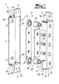
- the Fig.1 shows an exploded view of a receiving element according to the invention.
- the receiving element has a support 1 formed from a sheet steel and a counterpart 2 also formed from a sheet steel.
- the components of a fastening device 3 are shown explosively, which is arranged in the mounted state in a space enclosed by the support 1 and the counterpart 2 receiving space 4.
- the carrier 1 has a two side legs 5 and the two side legs 5 connecting connecting leg 6 existing U-shaped section. At the end facing away from the connecting leg 6 of the side legs 5 are mounting flanges 7 from. These are arranged substantially parallel to the connecting leg 6 and, in the present exemplary embodiment, have welding bosses 8 for easier mounting on a steel frame.
- the counterpart 2 includes a cover plate 9, which is arranged in the mounted state at the opposite end of the receiving space 4 and substantially parallel to the connecting leg 6.
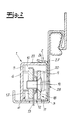
- a comparative consideration with the Fig. 2 one assumes that there abut two of the cover plate 9 projecting abutment leg 10 with its outer surfaces inside on the inner sides of the side legs 5.
- the front leg 11 is fastened to the carrier 1 by means of a latching connection.
- the front leg 11 has two latching lugs 14, which engage in each case in an associated, arranged on a side leg 5 notch 15.
- the locking lugs 14 and the side legs 5 each have an insertion bevel 16a, 16b.
- the fastening device 3 is used for fixing the inserted into the receiving space 4 hinge plate 13 and is supported on the connecting leg 6 and the cover plate 9.
- the hinge plate 13 is clamped between a guide plate 17 and a clamping plate 18 by three clamping screws 19.
- the fastening device 3 is arranged displaceably in the tape receiving element along an axis.
- the guide plate 17 is movably guided along two adjusting spindles 20.
- the adjusting spindles 20 surround with a concave portion projections 21, which are formed from the sheet of the connecting leg 6. With a concave portion opposite the tapered portion on which a hexagonal opening is arranged for receiving an adjusting tool, the adjusting spindles 20 engage in associated openings 22 of the cover plate 9 a. As a result, the adjusting spindles 20 are rotatably mounted on two sides and securely held between the carrier 1 and the counterpart 2.
- the carrier 1 has a side leg 5 of the U-shaped section perpendicular rear leg 23.
- the contact legs 10 of the counterpart 2 with their rear edges to the front of the rear leg 23.
- a web 24 is bent, which engages around the rear leg 23 and rests against the rear side.
- the web 24 is chamfered at its end to facilitate insertion of the rear leg 23 of the carrier 1 between the web 24 and the abutment legs 10.
- the web 24 overlaps the rear leg 23 only to a small extent.
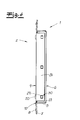
- the web 24 extends almost over the entire width of the rear web 23rd
- the latching connection is formed by a sheet metal tongue 29, which is notched out of the sheet of the rear leg 23 and bent by a small angle.
- the sheet metal tongue 29 cooperates with an associated opening 30 of the web 24.
- the rear leg 23 opposite to the front end of the connecting leg 6, an angle 31 for stabilizing the U-shaped support is arranged.
- the front surface of the angle 31 terminates flush with the front of the front leg 11.
- Angle 31 and front legs 11 abut each other with their end faces and are supported on each other.
- ramp-shaped locking boss 25 are arranged, which cooperate with associated latching windows 26 of the plant leg 10.
- the Rastbuckel 25 are formed by local deformation of the side legs 5.
- the in the Fig. 2 and 3 each section shown represents an installation situation.
- the receiving element according to the invention is on the inside of a Steel frame 27 arranged.
- the carrier 1 is welded to the mounting flanges 7 on the inside of the steel frame 27.
- the counterpart 2 is clamped between the steel frame 27 and the carrier 1. Additional holding forces are generated by the latching connection according to the invention.
- the clamping screws 19 and the adjusting spindles 20 are accessible through associated recesses 28 in steel frame 27 and cover plate 9 from the outside.
- Fig. 4 is the back of the receiving element in the embodiment according to Fig. 3 shown.
- the reference numbers are limited to the lower half, but are also used in the symmetrical upper part application.
- the web 24 covers the back of the rear web 23 almost completely.
- the web 24 is pierced by latching windows 30 in which associated sheet metal tongues 29 engage. Two of these snap-in connections 29, 30 are arranged in alignment with the axis of rotation of the adjusting spindles 20.
Abstract
Die Erfindung betrifft ein Aufnahmeelement für eine Stahlzarge mit einem Träger (1), welcher aus zwei Seitenschenkeln (5) und einem die beiden Seitenschenkel (5) verbindenden Verbindungsschenkel (6) bestehenden U-förmigen Abschnitt aufweist. An die Seitenschenkel (5) schließen jeweils Befestigungsflansche (7) an. Das Aufnahmeelement umfasst ferner ein Gegenstück (2), welches mit dem Träger (1) einen Aufnahmeraum (4) umschließt und eine dem Verbindungsschenkel (6) gegenüber angeordnete Deckplatte (9) aufweist. In dem Aufnahmeraum (4) ist eine Befestigungseinrichtung (3) zur Fixierung eines in den Aufnahmeraum (4) eingeschobenen Bandlappens (13) eines Türbandes angeordnet. Die Befestigungseinrichtung (3) ist an dem Verbindungsschenkel (6) und an der Deckplatte (9) abgestützt. Von der Deckplatte (9) stehen zwei Anlageschenkel (10) ab, welche mit ihren Außenflächen innenseitig an den Innenseiten der Seitenschenkel (5) anliegen. An der Vorderseite der Deckplatte (9) schließt ein Frontschenkel (11) mit einer Ausnehmung (12) zum Einschieben des Bandlappens (13) in den Aufnahmeraum (4) an. Erfindungsgemäß ist der Frontschenkel (11) mittels einer Rastverbindung an dem Träger (1) befestigt.The invention relates to a receiving element for a steel frame with a support (1), which has two U-shaped section consisting of two side legs (5) and a connecting leg (6) connecting the two side legs (5). Attach to the side legs (5) each mounting flanges (7). The receiving element further comprises a counterpart (2) which encloses a receiving space (4) with the carrier (1) and has a cover plate (9) arranged opposite the connecting leg (6). In the receiving space (4) a fastening device (3) for fixing a in the receiving space (4) inserted band tab (13) of a door hinge is arranged. The fastening device (3) is supported on the connecting leg (6) and on the cover plate (9). From the cover plate (9) are two bearing limbs (10) from which rest with their outer surfaces on the inside of the inner sides of the side legs (5). At the front of the cover plate (9) includes a front leg (11) with a recess (12) for insertion of the hinge flap (13) in the receiving space (4). According to the invention, the front leg (11) is fastened to the carrier (1) by means of a latching connection.
Description
Die Erfindung betrifft ein Aufnahmeelement für eine Stahlzarge zur Aufnahme eines Türbandes mit einem Träger. Der Träger weist einen aus zwei Seitenschenkeln und einem die beiden Seitenschenkel verbindenden Verbindungsschenkel bestehenden U-förmigen Abschnitt und zwei jeweils an einen Seitenschenkel anschließende Befestigungsflansche auf. Zu dem Aufnahmeelement gehört ebenfalls ein Gegenstück, welches mit dem Träger einen Aufnahmeraum umschließt und eine dem Verbindungsschenkel gegenüber angeordnete Deckplatte aufweist. In dem Aufnahmeraum ist eine Befestigungseinrichtung zur Fixierung eines in den Aufnahmeraum eingeschobenen Bandlappens eines Türbandes angeordnet, welche an dem Verbindungsschenkel und der Deckplatte abgestützt ist. Von der Deckplatte stehen zwei Anlageschenkel ab, welche mit ihren Außenflächen innenseitig an den Innenseiten der Seitenschenkel anliegen und wobei an die Vorderseite der Deckplatte ein Frontschenkel mit einer Ausnehmung zum Einschieben des Bandlappens in den Aufnahmeraum anschließt.The invention relates to a receiving element for a steel frame for receiving a door hinge with a carrier. The carrier has a two side legs and a connecting leg connecting the two side legs existing U-shaped portion and two adjoining each side leg mounting flanges. To the receiving element also includes a counterpart, which encloses a receiving space with the carrier and having a connecting leg opposite cover plate. In the receiving space, a fastening device for fixing an inserted into the receiving space hinge strap of a door hinge is arranged, which is supported on the connecting leg and the cover plate. From the cover plate are two bearing limbs, which abut with their outer surfaces on the inside of the inner sides of the side legs and wherein the front of the cover plate is followed by a front leg with a recess for insertion of the hinge strap in the receiving space.
Ein derartiges Aufnahmeelement ist aus
Hierbei ist nachteilig, dass ein solches Aufnahmeelement nur begrenzt belastet werden kann. Bei besonders schweren Türblättern, wie z. B. bei Brandschutzoder Krankenhaustüren ist diese Art der Abstützung nicht mehr ausreichend. Das Aufnahmeelement kann durch die Anpresskraft an die Stahlzarge nicht mehr sicher zusammengehalten werden.It is disadvantageous that such a receiving element can be charged only limited. For particularly heavy door leaves, such. As fire protection or hospital doors this type of support is no longer sufficient. The receiving element can no longer be securely held together by the contact pressure on the steel frame.
Vor diesem Hintergrund liegt der Erfindung die Aufgabe zugrunde, mit einfachen Mitteln die Belastbarkeit des Aufnahmeelementes zu verbessern, ohne dass hierdurch der Vormontage- oder der Montageprozess erschwert werden.Against this background, the object of the invention is to improve the load capacity of the receiving element with simple means, without this making the pre-assembly or assembly process more difficult.
Lösung dieser Aufgabe und Gegenstand der Erfindung ist ein Aufnahmeelement mit den Merkmalen von Anspruch 1 sowie eine Stahlzarge mit den Merkmalen von Anspruch 15.Solution to this problem and subject of the invention is a receiving element with the features of
Erfindungsgemäß ist der Frontschenkel mittels zumindest einer Rastverbindung an dem Träger befestigt. Eine solche Rastverbindung führt zu keinem zusätzlichen Aufwand während der Vormontage, da diese bereits durch das Einlegen des Gegenstücks in dem Träger verriegelt werden kann. Die Rastverbindung ist dabei so ausgerichtet, dass sie ein Auseinanderziehen von Gegenstück und Träger verhindert. Da bereits Relativbewegungen in allen anderen Richtungen durch das U-förmige Profil des Trägers verhindert werden, ist das Gegenstück durch die erfindungsgemäße Rastverbindung in allen Bewegungsrichtungen sicher festgelegt.According to the invention, the front leg is fastened to the carrier by means of at least one latching connection. Such a latching connection leads to no additional effort during pre-assembly, since this can already be locked by inserting the counterpart in the carrier. The latching connection is aligned so that it prevents a pulling apart of counterpart and carrier. Since already relative movements in all other directions are prevented by the U-shaped profile of the carrier, the counterpart is securely fixed by the locking connection according to the invention in all directions of movement.
Vorzugsweise weist der Frontschenkel zumindest eine Rastnase auf, welche in eine an einem Seitenschenkel angeordnete, zugeordnete Auskerbung eingreift und dadurch die Rastverbindung bildet. Die Rastnase und/oder das die Auskerbung umgebende Blech kann mit einer Einführschräge ausgestattet sein, welche das Einschieben des Gegenstücks in den Träger vereinfacht. Rastnase und Auskerbung können während des Produktionsprozesses mit einfachen Mitteln aus einem Blechmaterial hergestellt werden.Preferably, the front leg has at least one latching lug, which engages in a, arranged on a side leg, associated notch and thereby forms the latching connection. The locking lug and / or the sheet surrounding the notch may be equipped with an insertion bevel, which simplifies the insertion of the counterpart in the carrier. Latch and notch can be made during the production process with simple means of a sheet material.
In einer bevorzugten Ausgestaltung weist der Träger einen zu den Seitenschenkeln des U-förmigen Abschnittes senkrecht stehenden hinteren Schenkel auf. Die Anlageschenkel des Gegenstücks stoßen dabei mit ihren hinteren Kanten auf die Vorderseite des hinteren Schenkels. Hierdurch ergibt sich eine zusätzliche Führung.In a preferred embodiment, the carrier has a rear leg perpendicular to the side legs of the U-shaped section. The plant legs of the counterpart meet with their rear edges on the front of the rear leg. This results in an additional leadership.
An der Hinterseite der Deckplatte ist bevorzugt ein Steg umgebogen, welcher den hinteren Schenkel umgreift und an dessen Rückseite anliegt. Durch eine solche Ausgestaltung wird eine sichere Führung und Lagerung des Gegenstücks an dem Träger gewährleistet. Aufgrund dieser Lagerung ist das Gegenstück nur in einem Freiheitsgrad bewegbar, wobei diese Bewegung durch die erfindungsgemäße Rastverbindung sicher unterbunden werden kann.At the rear of the cover plate, a web is preferably bent, which surrounds the rear leg and rests against the rear side. Such a configuration ensures secure guidance and storage of the counterpart on the carrier. Because of this storage, the counterpart is movable only in one degree of freedom, said movement can be reliably prevented by the latching connection according to the invention.
Zweckmäßigerweise deckt der Steg mehr als 50 %, insbesondere mehr als 75 % der Rückseite des hinteren Schenkels ab. Hierdurch teilen sich der Steg und der hintere Schenkel eine besonders große Anlagefläche, welche eine sichere Abstützung gewährleistet.Conveniently, the web covers more than 50%, in particular more than 75% of the back of the rear leg. As a result, the web and the rear leg share a particularly large contact surface, which ensures a secure support.
In einer besonders bevorzugten Ausgestaltung sind der Steg und der hintere Schenkel mittels zumindest einer Rastverbindung aneinander befestigt. Dazu können beispielsweise Rastelemente aus Blechzungen gebildet sein, welche aus dem Blechmaterial ausgeklinkt und um einen geringen Winkel umgebogen werden. Hierdurch bildet die Oberfläche der Zunge eine aus der Ebene des Bleches kontinuierlich ansteigende Auflaufschräge und die ausgeklinkte Abschlusskante ein Widerlager der Rastverbindung. Eine solche Blechzunge kann mit einem zugeordneten Schlitz oder Fenster in dem korrespondierenden Teil zusammenwirken. Die Abschlusskante der Blechzunge liegt im verrasteten Zustand an der Innenseite des Fensters oder Schlitzes an.In a particularly preferred embodiment, the web and the rear leg are fastened to each other by means of at least one latching connection. For this example, locking elements may be formed from sheet metal tongues, which are notched out of the sheet material and bent by a small angle. As a result, the surface of the tongue forms a bevel rising continuously from the plane of the sheet, and the notched end edge forms an abutment of the snap-in connection. Such a tongue tongue may cooperate with an associated slot or window in the corresponding part. The end edge of the tongue is in the locked state on the inside of the window or slot.
Bevorzugt fluchtet zumindest eine Rastverbindung zwischen Steg und hinterem Schenkel mit der Befestigung der Befestigungseinrichtung an dem Träger und Gegenstück.Preferably, at least one latching connection between the web and the rear leg is aligned with the attachment of the fastening device to the carrier and counterpart.
Zweckmäßigerweise ist die Befestigungseinrichtung in zumindest einer Raumrichtung verstellbar. Hierdurch lässt sich die Position des in dem Aufnahmeelement gehaltenen Bandlappens den Anforderungen entsprechend einstellen, z.B. kann die Position und/oder der Andruck des Türflügels festgelegt werden.Conveniently, the fastening device is adjustable in at least one spatial direction. In this way, the position of the band tab held in the receiving element can be adjusted according to requirements, e.g. the position and / or the pressure of the door leaf can be determined.
Vorzugsweise ist die Befestigungseinrichtung mit Verstellspindeln entlang einer Achse verschiebbar. Verstellspindeln stellen einen mechanisch besonders einfachen, selbstsichernden linearen Einstellantrieb dar.Preferably, the fastening device with adjusting spindles is displaceable along an axis. Adjusting spindles represent a mechanically particularly simple, self-locking linear adjustment drive.
In einer besonders bevorzugten Ausgestaltung sind die Verstellspindeln auf Ausbuchtungen des Verbindungsschenkels drehbar gelagert. Hierdurch entfallen zusätzliche Bohrungen und/oder Teile zur drehbaren Lagerung, wodurch der Herstellungsprozess weiter vereinfacht und die Herstellungskosten gesenkt werden können.In a particularly preferred embodiment, the adjusting spindles are rotatably mounted on bulges of the connecting leg. This eliminates additional holes and / or parts for rotatable mounting, whereby the manufacturing process can be further simplified and the manufacturing cost can be reduced.
Zweckmäßigerweise weisen die Befestigungsflansche Schweißbuckel auf. Diese dienen beim Verbindungsschweißen zu der Stahlzarge als definierte Anlagepunkte und vereinfachen hierdurch das (Elektro-) Schweißen.Conveniently, the mounting flanges on welding humps. These serve as defined contact points during connection welding to the steel frame and thereby simplify (electro) welding.
Zur weiteren Stabilisierung von Träger und Gegenstück lehrt eine bevorzugte Ausführung, dass die Seitenschenkel und die zugeordneten Anlageschenkel jeweils mittels zumindest einer Rastverbindung aneinander befestigt sind. Die Rastverbindung kann beispielsweise durch einen in das Blech eingeprägten rampenförmigen Rastbuckel und ein zugeordnetes Rastfenster gebildet sein. Diese zusätzliche Rastverbindung an den Schmalseiten des Aufnahmeelementes ist besonders stabil, da der durch die Befestigungsflansche fixierte U-förmige Träger in einer Einbausituation nicht mehr auseinandergedrückt werden kann. Zweckmäßigerweise fluchten die Rastverbindungen mit den Drehachsen der Verstellspindeln. Zur Vereinfachung der Montage kann bei einer Rastverbindung mit einem Rastfenster im Anlageschenkel zusätzlich an der von der Frontplatte abgewandten Seite des Anlageschenkels eine Aussparung mit der Breite des Rastfensters angeordnet sein. Zwischen Aussparung und Rastfenster verbleibt ein Steg, so dass die Stabilität des Anlageschenkels nicht in Mitleidenschaft gezogen wird. Bei der Montage kann das Gegenstück mit der Aussparung auf dem zugeordneten Rastbuckel der Außenschenkel positioniert werden. Durch anschließende Druckbelastung wird der Rastbuckel in das Rastfenster geschoben und erzeugt so die Rastverbindung.To further stabilize the carrier and its counterpart, a preferred embodiment teaches that the side legs and the associated bearing limbs are fastened to one another in each case by means of at least one latching connection. The latching connection can be formed, for example, by a stamped into the sheet ramp-shaped Rastbuckel and an associated latching window. This additional locking connection on the narrow sides of the receiving element is particularly stable because the fixed by the mounting flanges U-shaped support in an installation situation can not be pushed apart. Conveniently, the locking connections are aligned with the axes of rotation of the adjusting spindles. To simplify the assembly can be arranged with a recess with the width of the latching window at a locking connection with a locking window in the plant leg in addition to the side facing away from the front panel side of the support leg. Between recess and locking window remains a bridge, so that the stability of the plant leg is not affected. During assembly, the counterpart can be positioned with the recess on the associated latching hump of the outer leg. By subsequent pressure loading of the Rastbuckel is pushed into the locking window and thus generates the locking connection.
Zweckmäßigerweise sind Träger und/oder Gegenstück aus einem schweißbaren Metallblech gefertigt. Die in den Ausführungsbeispielen beschriebenen Formen lassen sich insbesondere durch Schneid- und Biegeoperationen eines Metallbleches herstellen. Das so hergestellte Aufnahmeelement weist eine einheitliche Wandstärke auf. Durch lokale Umformung und Einschnitte können die Elemente der erfindungsgemäßen Rastverbindungen gebildet werden.Conveniently, the carrier and / or counterpart are made of a weldable sheet metal. The forms described in the embodiments can be produced in particular by cutting and bending operations of a metal sheet. The receiving element produced in this way has a uniform wall thickness. By local deformation and cuts the elements of the snap-in connections according to the invention can be formed.
In einer bevorzugten Ausgestaltung ist an der Frontseite des Verbindungsschenkels ein Winkel abgekantet. Dieser ist zweckmäßigerweise zur Seite des Aufnahmeraumes um einen Winkel von etwa 90° umgebogen. Hierdurch wird eine zusätzliche Stabilisierung des U-förmigen Trägers erreicht. Ein Durchbiegen des Verbindungsschenkels wird erschwert.In a preferred embodiment, an angle is bent on the front side of the connecting leg. This is suitably bent to the side of the receiving space by an angle of about 90 °. As a result, an additional stabilization of the U-shaped carrier is achieved. A bending of the connecting leg is made more difficult.
Besonders bevorzugt erstreckt sich der Winkel im Wesentlichen über die gesamte Länge - jedoch zumindest 95 % - der Länge des Verbindungsschenkels. Um ein einheitliches Erscheinungsbild zu erzeugen, können die Frontseite des Winkels und der Frontschenkel des Gegenstücks eine bündige Abschlussfläche bilden.Particularly preferably, the angle extends substantially over the entire length - but at least 95% - of the length of the connecting leg. To create a uniform appearance, the Front of the angle and the front legs of the counterpart form a flush finish.
Zweckmäßigerweise stoßen Winkel und Frontschenkel mit ihren Stirnseiten gegeneinander und bilden so eine zusätzliche Abstützung.Conveniently, the angles and front legs abut each other with their end faces and thus form an additional support.
Ein weiterer Aspekt der Erfindung besteht darin, dass eine Stahlzarge mit zumindest einem zuvor beschriebenen Aufnahmeelement versehen ist. Durch das besonders stabile Aufnahmeelement ist die Stahlzarge geeignet, besonders schwere Türen zu tragen.Another aspect of the invention is that a steel frame is provided with at least one receiving element described above. Due to the particularly stable receiving element, the steel frame is suitable for carrying particularly heavy doors.
Zweckmäßigerweise ist das Aufnahmeelement mit der Innenseite der Stahlzarge verschweißt. Aber auch andere Verbindungsmethoden wie beispielsweise Verschrauben oder Vernieten sind ohne Einschränkung verwendbar.Conveniently, the receiving element is welded to the inside of the steel frame. But other connection methods such as screwing or riveting can be used without restriction.
Bevorzugter Weise ist das Gegenstück zwischen der Stahlzarge und dem damit verschweißten Träger eingespannt. Hierdurch wird die durch ein in dem Aufnahmeelement gehaltenes Türblatt ausgeübte Last nicht allein von der Rastverbindung oder dem Zusammenwirken von Stahlzarge und Träger gehalten, sondern verteilt sich darauf gleichmäßig.Preferably, the counterpart between the steel frame and the carrier welded thereto is clamped. As a result, the load exerted by a held in the receiving element door leaf load is not held solely by the latching connection or the interaction of steel frame and carrier, but distributed evenly.
Besonders bevorzugt sind die Klemmmittel und/oder Verstellspindeln des Aufnahmeelements durch Aussparungen an der Stahlzarge zugänglich. Hierdurch kann ein in dem Aufnahmeelement gehaltenes Türband auch nachträglich verstellt und/oder entfernt werden.Particularly preferably, the clamping means and / or adjusting spindles of the receiving element are accessible through recesses on the steel frame. In this way, a held in the receiving element door hinge can also be subsequently adjusted and / or removed.
Die Erfindung soll anhand den nachfolgenden, lediglich ein Ausführungsbeispiel darstellenden Zeichnungen erläutert werden. Es zeigen schematisch
- Fig. 1
- eine Explosionsdarstellung eines erfindungsgemäßen Aufnahmeelementes,
- Fig. 2
- einen Horizontalschnitt durch ein in einer Stahlzarge montiertes erfindungsgemäßes Aufnahmeelement,
- Fig. 3
- einen Horizontalschnitt durch ein in einer Stahlzarge montiertes Aufnahmeelement gemäß einer alternativen Ausgestaltung der Erfindung und
- Fig. 4
- eine Rückansicht des in
Fig. 3 dargestellten Aufnahmeelementes.
- Fig. 1
- an exploded view of a receiving element according to the invention,
- Fig. 2
- a horizontal section through a mounted in a steel frame inventive receiving element,
- Fig. 3
- a horizontal section through a mounted in a steel frame receiving element according to an alternative embodiment of the invention and
- Fig. 4
- a rear view of the in
Fig. 3 shown receiving element.
Die
Zu dem Gegenstück 2 gehört eine Deckplatte 9, welche im montierten Zustand am gegenüberliegenden Ende des Aufnahmeraumes 4 und im Wesentlichen parallel zum Verbindungsschenkel 6 angeordnet ist. Einer vergleichenden Betrachtung mit der
Die Befestigungseinrichtung 3 dient zur Fixierung des in den Aufnahmeraum 4 eingeschobenen Bandlappens 13 und ist an dem Verbindungsschenkel 6 und der Deckplatte 9 abgestützt. Dazu wird der Bandlappen 13 zwischen einer Führungsplatte 17 und einer Klemmplatte 18 durch drei Klemmschrauben 19 eingespannt.The
Zusätzlich ist die Befestigungseinrichtung 3 entlang einer Achse verschiebbar in dem Bandaufnahmeelement angeordnet. Dazu ist die Führungsplatte 17 entlang zweier Verstellspindeln 20 bewegbar geführt. Die Verstellspindeln 20 umgreifen mit einem konkaven Bereich Vorsprünge 21, welche aus dem Blech des Verbindungsschenkels 6 ausgeformt sind. Mit einem dem konkaven Abschnitt gegenüberliegenden verjüngten Bereich, an dem auch eine Sechskantöffnung zur Aufnahme eines Verstellwerkzeuges angeordnet ist, greifen die Verstellspindeln 20 in zugeordnete Öffnungen 22 der Deckplatte 9 ein. Dadurch sind die Verstellspindeln 20 an zwei Seiten drehbar gelagert und sicher zwischen dem Träger 1 und dem Gegenstück 2 gehalten.In addition, the
Weiterhin weist der Träger 1 einen zu den Seitenschenkeln 5 des U-förmigen Abschnittes senkrecht stehenden hinteren Schenkel 23 auf. Im zusammengesetzten Zustand stoßen die Anlageschenkel 10 des Gegenstücks 2 mit ihren hinteren Kanten auf die Vorderseite des hinteren Schenkels 23. An der Hinterseite der Deckplatte 9 ist ein Steg 24 umgebogen, der den hinteren Schenkel 23 umgreift und an dessen Rückseite anliegt. Der Steg 24 ist an seinem Ende abgeschrägt, um ein Einführen des hinteren Schenkels 23 des Trägers 1 zwischen dem Steg 24 und den Anlageschenkeln 10 zu vereinfachen. In den Ausführungen gemäß
In dem Ausführungsbeispiel gemäß
An den Seitenschenkeln 5 sind rampenförmige Rastbuckel 25 angeordnet, welche mit zugeordneten Rastfenstern 26 der Anlageschenkel 10 zusammenwirken. Die Rastbuckel 25 sind durch lokale Umformung der Seitenschenkel 5 gebildet.On the
Der in den
In der
In dem Ausführungsbeispiel nach den
Claims (18)
mit einem Träger (1), welcher einen aus zwei Seitenschenkeln (5) und einem die beiden Seitenschenkel (5) verbindenden Verbindungsschenkel (6) bestehenden U-förmigen Abschnitt und zwei jeweils an einen Seitenschenkel (5) anschließende Befestigungsflansche (7) aufweist,
mit einem Gegenstück (2), welches mit dem Träger (1) einen Aufnahmeraum (4) umschließt und eine dem Verbindungsschenkel (6) gegenüber angeordnete Deckplatte (9) aufweist, und
mit einer in dem Aufnahmeraum (4) angeordneten Befestigungseinrichtung (3) zur Fixierung eines in den Aufnahmeraum (4) eingeschobenen Bandlappens (13) eines Türbandes, welche an dem Verbindungsschenkel (6) und der Deckplatte (9) abgestützt ist,
wobei von der Deckplatte (9) zwei Anlageschenkel (10) abstehen, welche mit ihren Außenflächen innenseitig an den Innenseiten der Seitenschenkel (5) anliegen, und wobei an die Vorderseite der Deckplatte (9) ein Frontschenkel (11) mit einer Ausnehmung (12) zum Einschieben des Bandlappens (13) in den Aufnahmeraum (4) anschließt, dadurch gekennzeichnet, dass der Frontschenkel (11) mittels zumindest einer Rastverbindung an dem Träger (1) befestigt ist.Receiving element for a steel frame (27)
with a carrier (1), which has a U-shaped section consisting of two side legs (5) and a connecting leg (6) connecting the two side legs (5) and two fastening flanges (7) each adjoining a side leg (5),
with a counterpart (2) which encloses a receiving space (4) with the carrier (1) and has a cover plate (9) arranged opposite the connecting leg (6), and
with a fastening device (3) arranged in the receiving space (4) for fixing a hinge (13) of a door hinge inserted in the receiving space (4), which is supported on the connecting leg (6) and the cover plate (9),
wherein from the cover plate (9) two abutment legs (10) protrude, which abut with their outer surfaces on the inside of the inner sides of the side legs (5), and wherein at the front of the cover plate (9) has a front leg (11) with a recess (12) for insertion of the hinge flap (13) in the receiving space (4) connects, characterized in that the front leg (11) by means of at least one latching connection to the support (1) is attached.
Priority Applications (1)
| Application Number | Priority Date | Filing Date | Title |
|---|---|---|---|
| PL14190287T PL2876238T3 (en) | 2013-11-26 | 2014-10-24 | Receiving element for a steel door frame and steel door frame with the same |
Applications Claiming Priority (1)
| Application Number | Priority Date | Filing Date | Title |
|---|---|---|---|
| DE201310113056 DE102013113056B3 (en) | 2013-11-26 | 2013-11-26 | Receiving element for retaining door hinge in steel frame, has cover plate including front leg with recess for insertion of hinge strap into receiving space, where front leg is attached to support by snap connection |
Publications (2)
| Publication Number | Publication Date |
|---|---|
| EP2876238A1 true EP2876238A1 (en) | 2015-05-27 |
| EP2876238B1 EP2876238B1 (en) | 2019-04-17 |
Family
ID=51019337
Family Applications (1)
| Application Number | Title | Priority Date | Filing Date |
|---|---|---|---|
| EP14190287.4A Active EP2876238B1 (en) | 2013-11-26 | 2014-10-24 | Receiving element for a steel door frame and steel door frame with the same |
Country Status (6)
| Country | Link |
|---|---|
| US (1) | US9650819B2 (en) |
| EP (1) | EP2876238B1 (en) |
| CN (1) | CN104675245B (en) |
| DE (1) | DE102013113056B3 (en) |
| PL (1) | PL2876238T3 (en) |
| RU (1) | RU2672023C2 (en) |
Families Citing this family (6)
| Publication number | Priority date | Publication date | Assignee | Title |
|---|---|---|---|---|
| DE202015104235U1 (en) * | 2015-08-11 | 2015-08-19 | Simonswerk, Gesellschaft mit beschränkter Haftung | Door construction and mounting element for this |
| CH711502A1 (en) * | 2015-09-08 | 2017-03-15 | Keller Zargen Ag | <TITLE> Metal frame profile. |
| CN108756551B (en) * | 2018-05-26 | 2019-10-22 | 浙江鼎立实业有限公司 | A kind of realized using screw thread self-locking function can the parked door hinge of random angle |
| CA3057670A1 (en) | 2019-08-29 | 2021-02-28 | L.E. Johnson Products, Inc. | Pocket door frame |
| USD959239S1 (en) * | 2019-10-03 | 2022-08-02 | L.E. Johnson Products, Inc. | Pocket door frame stud |
| USD960687S1 (en) * | 2019-12-18 | 2022-08-16 | Randy C. Underwood | Gate hanging bracket |
Citations (2)
| Publication number | Priority date | Publication date | Assignee | Title |
|---|---|---|---|---|
| DE19930448A1 (en) | 1999-07-02 | 2001-01-11 | Simonswerk Gmbh | Fastening device for hinge hinges |
| DE102009017029B3 (en) * | 2009-04-09 | 2010-08-26 | Simonswerk, Gesellschaft mit beschränkter Haftung | Band support for steel frame, has flange attached to inner surface of steel frame, which is extended to front side of wall protection box, and holding piece supported at side wall, upper wall and lower wall of protection box |
Family Cites Families (11)
| Publication number | Priority date | Publication date | Assignee | Title |
|---|---|---|---|---|
| US923250A (en) * | 1908-11-17 | 1909-06-01 | Brown Davis Hardware Company | Hinge. |
| DE1683591A1 (en) * | 1968-03-08 | 1971-02-11 | Franz Schwarte Fa | Wall protection box for steel frames |
| US5075928A (en) * | 1990-08-17 | 1991-12-31 | The Stanley Works | Concealed architectural hinge assembly |
| US5193308A (en) * | 1992-07-22 | 1993-03-16 | The Stanley Works | Snap-in hinge for doors with hollow metal frames |
| DE10153778B4 (en) * | 2001-10-31 | 2004-07-22 | Simonswerk, Gmbh | Concealed door hinge for swiveling mounting of a door leaf on a door frame |
| US20060076348A1 (en) * | 2004-10-12 | 2006-04-13 | Thomas & Betts International, Inc. | Electrical outlet box having attachable walls |
| US20090057303A1 (en) * | 2007-08-31 | 2009-03-05 | Leviton Manufacturing Company, Inc. | Modular wall housing unit for electrical components |
| CN201363026Y (en) * | 2008-12-30 | 2009-12-16 | 邓超 | 180 degrees integral rotation adjustable concealed hinge |
| CN201763102U (en) * | 2010-08-26 | 2011-03-16 | 宋武景 | Left and right adjustable plastic steel window hinge |
| CN202249364U (en) * | 2011-09-16 | 2012-05-30 | 叶庆荣 | Hinge set hidden structure for door frame and door leaf |
| CN203034974U (en) * | 2012-12-06 | 2013-07-03 | 叶庆荣 | A concealed hinge and a combination structure thereof |
-
2013
- 2013-11-26 DE DE201310113056 patent/DE102013113056B3/en active Active
-
2014
- 2014-10-24 EP EP14190287.4A patent/EP2876238B1/en active Active
- 2014-10-24 PL PL14190287T patent/PL2876238T3/en unknown
- 2014-11-21 US US14/550,252 patent/US9650819B2/en active Active
- 2014-11-25 CN CN201410685771.9A patent/CN104675245B/en not_active Expired - Fee Related
- 2014-11-25 RU RU2014147456A patent/RU2672023C2/en active
Patent Citations (2)
| Publication number | Priority date | Publication date | Assignee | Title |
|---|---|---|---|---|
| DE19930448A1 (en) | 1999-07-02 | 2001-01-11 | Simonswerk Gmbh | Fastening device for hinge hinges |
| DE102009017029B3 (en) * | 2009-04-09 | 2010-08-26 | Simonswerk, Gesellschaft mit beschränkter Haftung | Band support for steel frame, has flange attached to inner surface of steel frame, which is extended to front side of wall protection box, and holding piece supported at side wall, upper wall and lower wall of protection box |
Also Published As
| Publication number | Publication date |
|---|---|
| RU2014147456A (en) | 2016-06-10 |
| CN104675245B (en) | 2018-08-31 |
| US9650819B2 (en) | 2017-05-16 |
| RU2672023C2 (en) | 2018-11-08 |
| DE102013113056B3 (en) | 2014-07-10 |
| EP2876238B1 (en) | 2019-04-17 |
| CN104675245A (en) | 2015-06-03 |
| RU2014147456A3 (en) | 2018-05-30 |
| PL2876238T3 (en) | 2019-09-30 |
| US20150143754A1 (en) | 2015-05-28 |
Similar Documents
| Publication | Publication Date | Title |
|---|---|---|
| EP2876238B1 (en) | Receiving element for a steel door frame and steel door frame with the same | |
| DE102015120542B3 (en) | Adjustable door hinge | |
| EP3572605A1 (en) | Hinge arrangement for a switchgear cabinet housing, and corresponding switchgear cabinet housing | |
| DE10115124A1 (en) | Security device for a door window of a motor vehicle | |
| AT519077B1 (en) | Device for releasably securing a front panel to a drawer and method for mounting or dismounting a front panel on a drawer | |
| EP3238569B1 (en) | Device for applying a rear wall to a mobile piece of furniture | |
| EP3197318B1 (en) | Adjustment device | |
| AT404380B (en) | DEVICE, IN PARTICULAR DISTANCE ANCHOR FOR ADJUSTMENT AND FASTENING OF FRAME | |
| EP1708592B1 (en) | Drawer comprising two lateral frames and a cover | |
| DE112018000009T5 (en) | Longitudinal adjuster for a vehicle seat | |
| EP3034734B1 (en) | Hinge for a door or a window | |
| EP2951374B1 (en) | Running part for guiding a furniture part in a guiding direction via a guiding rail, and furniture fitting | |
| DE102007053340A1 (en) | Corner guide for a drive rod fitting system for a window or door leaf | |
| DE202016106504U1 (en) | Assembly tool for mounting a cabinet door to a cabinet housing and a corresponding cabinet assembly | |
| WO2017072106A1 (en) | Guide assembly for sliding doors and cupboard unit | |
| EP2594165B1 (en) | Clamp holder for fixing an object, in particular a cable tensioning device for a sun screen or blind, to a window or door frame | |
| DE102015101575B4 (en) | Elongated polygonal profile and angle element and manufacturing method produced therefrom | |
| DE4342758C2 (en) | Door for vehicle body | |
| EP3173556A1 (en) | Mounting element for attaching door hinges | |
| DE102016004915B3 (en) | Fitting for a window, method for producing the fitting and corresponding window | |
| DE2423436A1 (en) | HINGE | |
| EP3665038A1 (en) | Longitudinal adjuster for a vehicle seat | |
| DE102021129914B3 (en) | door hinge | |
| EP1101008A1 (en) | Drive rod fitting with corner deflection | |
| EP2240651A1 (en) | Profiled strip device |
Legal Events
| Date | Code | Title | Description |
|---|---|---|---|
| PUAI | Public reference made under article 153(3) epc to a published international application that has entered the european phase |
Free format text: ORIGINAL CODE: 0009012 |
|
| 17P | Request for examination filed |
Effective date: 20141024 |
|
| AK | Designated contracting states |
Kind code of ref document: A1 Designated state(s): AL AT BE BG CH CY CZ DE DK EE ES FI FR GB GR HR HU IE IS IT LI LT LU LV MC MK MT NL NO PL PT RO RS SE SI SK SM TR |
|
| AX | Request for extension of the european patent |
Extension state: BA ME |
|
| R17P | Request for examination filed (corrected) |
Effective date: 20151126 |
|
| RBV | Designated contracting states (corrected) |
Designated state(s): AL AT BE BG CH CY CZ DE DK EE ES FI FR GB GR HR HU IE IS IT LI LT LU LV MC MK MT NL NO PL PT RO RS SE SI SK SM TR |
|
| GRAP | Despatch of communication of intention to grant a patent |
Free format text: ORIGINAL CODE: EPIDOSNIGR1 |
|
| STAA | Information on the status of an ep patent application or granted ep patent |
Free format text: STATUS: GRANT OF PATENT IS INTENDED |
|
| INTG | Intention to grant announced |
Effective date: 20181207 |
|
| GRAS | Grant fee paid |
Free format text: ORIGINAL CODE: EPIDOSNIGR3 |
|
| GRAA | (expected) grant |
Free format text: ORIGINAL CODE: 0009210 |
|
| STAA | Information on the status of an ep patent application or granted ep patent |
Free format text: STATUS: THE PATENT HAS BEEN GRANTED |
|
| AK | Designated contracting states |
Kind code of ref document: B1 Designated state(s): AL AT BE BG CH CY CZ DE DK EE ES FI FR GB GR HR HU IE IS IT LI LT LU LV MC MK MT NL NO PL PT RO RS SE SI SK SM TR |
|
| REG | Reference to a national code |
Ref country code: GB Ref legal event code: FG4D Free format text: NOT ENGLISH |
|
| REG | Reference to a national code |
Ref country code: CH Ref legal event code: EP |
|
| REG | Reference to a national code |
Ref country code: DE Ref legal event code: R096 Ref document number: 502014011446 Country of ref document: DE |
|
| REG | Reference to a national code |
Ref country code: AT Ref legal event code: REF Ref document number: 1121730 Country of ref document: AT Kind code of ref document: T Effective date: 20190515 Ref country code: IE Ref legal event code: FG4D Free format text: LANGUAGE OF EP DOCUMENT: GERMAN |
|
| REG | Reference to a national code |
Ref country code: CH Ref legal event code: NV Representative=s name: KELLER AND PARTNER PATENTANWAELTE AG, CH |
|
| REG | Reference to a national code |
Ref country code: NL Ref legal event code: FP |
|
| REG | Reference to a national code |
Ref country code: LT Ref legal event code: MG4D |
|
| PG25 | Lapsed in a contracting state [announced via postgrant information from national office to epo] |
Ref country code: ES Free format text: LAPSE BECAUSE OF FAILURE TO SUBMIT A TRANSLATION OF THE DESCRIPTION OR TO PAY THE FEE WITHIN THE PRESCRIBED TIME-LIMIT Effective date: 20190417 Ref country code: LT Free format text: LAPSE BECAUSE OF FAILURE TO SUBMIT A TRANSLATION OF THE DESCRIPTION OR TO PAY THE FEE WITHIN THE PRESCRIBED TIME-LIMIT Effective date: 20190417 Ref country code: HR Free format text: LAPSE BECAUSE OF FAILURE TO SUBMIT A TRANSLATION OF THE DESCRIPTION OR TO PAY THE FEE WITHIN THE PRESCRIBED TIME-LIMIT Effective date: 20190417 Ref country code: SE Free format text: LAPSE BECAUSE OF FAILURE TO SUBMIT A TRANSLATION OF THE DESCRIPTION OR TO PAY THE FEE WITHIN THE PRESCRIBED TIME-LIMIT Effective date: 20190417 Ref country code: NO Free format text: LAPSE BECAUSE OF FAILURE TO SUBMIT A TRANSLATION OF THE DESCRIPTION OR TO PAY THE FEE WITHIN THE PRESCRIBED TIME-LIMIT Effective date: 20190717 Ref country code: PT Free format text: LAPSE BECAUSE OF FAILURE TO SUBMIT A TRANSLATION OF THE DESCRIPTION OR TO PAY THE FEE WITHIN THE PRESCRIBED TIME-LIMIT Effective date: 20190817 Ref country code: FI Free format text: LAPSE BECAUSE OF FAILURE TO SUBMIT A TRANSLATION OF THE DESCRIPTION OR TO PAY THE FEE WITHIN THE PRESCRIBED TIME-LIMIT Effective date: 20190417 Ref country code: AL Free format text: LAPSE BECAUSE OF FAILURE TO SUBMIT A TRANSLATION OF THE DESCRIPTION OR TO PAY THE FEE WITHIN THE PRESCRIBED TIME-LIMIT Effective date: 20190417 |
|
| PG25 | Lapsed in a contracting state [announced via postgrant information from national office to epo] |
Ref country code: RS Free format text: LAPSE BECAUSE OF FAILURE TO SUBMIT A TRANSLATION OF THE DESCRIPTION OR TO PAY THE FEE WITHIN THE PRESCRIBED TIME-LIMIT Effective date: 20190417 Ref country code: LV Free format text: LAPSE BECAUSE OF FAILURE TO SUBMIT A TRANSLATION OF THE DESCRIPTION OR TO PAY THE FEE WITHIN THE PRESCRIBED TIME-LIMIT Effective date: 20190417 Ref country code: GR Free format text: LAPSE BECAUSE OF FAILURE TO SUBMIT A TRANSLATION OF THE DESCRIPTION OR TO PAY THE FEE WITHIN THE PRESCRIBED TIME-LIMIT Effective date: 20190718 Ref country code: BG Free format text: LAPSE BECAUSE OF FAILURE TO SUBMIT A TRANSLATION OF THE DESCRIPTION OR TO PAY THE FEE WITHIN THE PRESCRIBED TIME-LIMIT Effective date: 20190717 |
|
| PG25 | Lapsed in a contracting state [announced via postgrant information from national office to epo] |
Ref country code: IS Free format text: LAPSE BECAUSE OF FAILURE TO SUBMIT A TRANSLATION OF THE DESCRIPTION OR TO PAY THE FEE WITHIN THE PRESCRIBED TIME-LIMIT Effective date: 20190817 |
|
| REG | Reference to a national code |
Ref country code: DE Ref legal event code: R097 Ref document number: 502014011446 Country of ref document: DE |
|
| PG25 | Lapsed in a contracting state [announced via postgrant information from national office to epo] |
Ref country code: CZ Free format text: LAPSE BECAUSE OF FAILURE TO SUBMIT A TRANSLATION OF THE DESCRIPTION OR TO PAY THE FEE WITHIN THE PRESCRIBED TIME-LIMIT Effective date: 20190417 Ref country code: SK Free format text: LAPSE BECAUSE OF FAILURE TO SUBMIT A TRANSLATION OF THE DESCRIPTION OR TO PAY THE FEE WITHIN THE PRESCRIBED TIME-LIMIT Effective date: 20190417 Ref country code: EE Free format text: LAPSE BECAUSE OF FAILURE TO SUBMIT A TRANSLATION OF THE DESCRIPTION OR TO PAY THE FEE WITHIN THE PRESCRIBED TIME-LIMIT Effective date: 20190417 Ref country code: DK Free format text: LAPSE BECAUSE OF FAILURE TO SUBMIT A TRANSLATION OF THE DESCRIPTION OR TO PAY THE FEE WITHIN THE PRESCRIBED TIME-LIMIT Effective date: 20190417 Ref country code: RO Free format text: LAPSE BECAUSE OF FAILURE TO SUBMIT A TRANSLATION OF THE DESCRIPTION OR TO PAY THE FEE WITHIN THE PRESCRIBED TIME-LIMIT Effective date: 20190417 |
|
| PLBE | No opposition filed within time limit |
Free format text: ORIGINAL CODE: 0009261 |
|
| STAA | Information on the status of an ep patent application or granted ep patent |
Free format text: STATUS: NO OPPOSITION FILED WITHIN TIME LIMIT |
|
| PG25 | Lapsed in a contracting state [announced via postgrant information from national office to epo] |
Ref country code: SM Free format text: LAPSE BECAUSE OF FAILURE TO SUBMIT A TRANSLATION OF THE DESCRIPTION OR TO PAY THE FEE WITHIN THE PRESCRIBED TIME-LIMIT Effective date: 20190417 Ref country code: IT Free format text: LAPSE BECAUSE OF FAILURE TO SUBMIT A TRANSLATION OF THE DESCRIPTION OR TO PAY THE FEE WITHIN THE PRESCRIBED TIME-LIMIT Effective date: 20190417 |
|
| 26N | No opposition filed |
Effective date: 20200120 |
|
| PG25 | Lapsed in a contracting state [announced via postgrant information from national office to epo] |
Ref country code: TR Free format text: LAPSE BECAUSE OF FAILURE TO SUBMIT A TRANSLATION OF THE DESCRIPTION OR TO PAY THE FEE WITHIN THE PRESCRIBED TIME-LIMIT Effective date: 20190417 |
|
| PG25 | Lapsed in a contracting state [announced via postgrant information from national office to epo] |
Ref country code: MC Free format text: LAPSE BECAUSE OF FAILURE TO SUBMIT A TRANSLATION OF THE DESCRIPTION OR TO PAY THE FEE WITHIN THE PRESCRIBED TIME-LIMIT Effective date: 20190417 Ref country code: SI Free format text: LAPSE BECAUSE OF FAILURE TO SUBMIT A TRANSLATION OF THE DESCRIPTION OR TO PAY THE FEE WITHIN THE PRESCRIBED TIME-LIMIT Effective date: 20190417 |
|
| PG25 | Lapsed in a contracting state [announced via postgrant information from national office to epo] |
Ref country code: LU Free format text: LAPSE BECAUSE OF NON-PAYMENT OF DUE FEES Effective date: 20191024 |
|
| GBPC | Gb: european patent ceased through non-payment of renewal fee |
Effective date: 20191024 |
|
| REG | Reference to a national code |
Ref country code: CH Ref legal event code: PFA Owner name: SIMONSWERK, GESELLSCHAFT MIT BESCHRAENKTER HAF, DE Free format text: FORMER OWNER: SIMONSWERK, GESELLSCHAFT MIT BESCHRAENKTER HAFTUNG, DE |
|
| PG25 | Lapsed in a contracting state [announced via postgrant information from national office to epo] |
Ref country code: IE Free format text: LAPSE BECAUSE OF NON-PAYMENT OF DUE FEES Effective date: 20191024 Ref country code: GB Free format text: LAPSE BECAUSE OF NON-PAYMENT OF DUE FEES Effective date: 20191024 Ref country code: FR Free format text: LAPSE BECAUSE OF NON-PAYMENT OF DUE FEES Effective date: 20191031 |
|
| PG25 | Lapsed in a contracting state [announced via postgrant information from national office to epo] |
Ref country code: CY Free format text: LAPSE BECAUSE OF FAILURE TO SUBMIT A TRANSLATION OF THE DESCRIPTION OR TO PAY THE FEE WITHIN THE PRESCRIBED TIME-LIMIT Effective date: 20190417 |
|
| PG25 | Lapsed in a contracting state [announced via postgrant information from national office to epo] |
Ref country code: MT Free format text: LAPSE BECAUSE OF FAILURE TO SUBMIT A TRANSLATION OF THE DESCRIPTION OR TO PAY THE FEE WITHIN THE PRESCRIBED TIME-LIMIT Effective date: 20190417 Ref country code: HU Free format text: LAPSE BECAUSE OF FAILURE TO SUBMIT A TRANSLATION OF THE DESCRIPTION OR TO PAY THE FEE WITHIN THE PRESCRIBED TIME-LIMIT; INVALID AB INITIO Effective date: 20141024 |
|
| PGFP | Annual fee paid to national office [announced via postgrant information from national office to epo] |
Ref country code: NL Payment date: 20211020 Year of fee payment: 8 |
|
| PGFP | Annual fee paid to national office [announced via postgrant information from national office to epo] |
Ref country code: BE Payment date: 20211020 Year of fee payment: 8 |
|
| PG25 | Lapsed in a contracting state [announced via postgrant information from national office to epo] |
Ref country code: MK Free format text: LAPSE BECAUSE OF FAILURE TO SUBMIT A TRANSLATION OF THE DESCRIPTION OR TO PAY THE FEE WITHIN THE PRESCRIBED TIME-LIMIT Effective date: 20190417 |
|
| PGFP | Annual fee paid to national office [announced via postgrant information from national office to epo] |
Ref country code: PL Payment date: 20221014 Year of fee payment: 9 |
|
| REG | Reference to a national code |
Ref country code: NL Ref legal event code: MM Effective date: 20221101 |
|
| REG | Reference to a national code |
Ref country code: BE Ref legal event code: MM Effective date: 20221031 |
|
| PG25 | Lapsed in a contracting state [announced via postgrant information from national office to epo] |
Ref country code: NL Free format text: LAPSE BECAUSE OF NON-PAYMENT OF DUE FEES Effective date: 20221101 |
|
| PG25 | Lapsed in a contracting state [announced via postgrant information from national office to epo] |
Ref country code: BE Free format text: LAPSE BECAUSE OF NON-PAYMENT OF DUE FEES Effective date: 20221031 |
|
| PGFP | Annual fee paid to national office [announced via postgrant information from national office to epo] |
Ref country code: DE Payment date: 20231024 Year of fee payment: 10 Ref country code: CH Payment date: 20231102 Year of fee payment: 10 Ref country code: AT Payment date: 20231020 Year of fee payment: 10 |
|
| PGFP | Annual fee paid to national office [announced via postgrant information from national office to epo] |
Ref country code: PL Payment date: 20231013 Year of fee payment: 10 |