EP2876193A1 - Cleaning device, drafting device, and spinning unit - Google Patents
Cleaning device, drafting device, and spinning unit Download PDFInfo
- Publication number
- EP2876193A1 EP2876193A1 EP14190657.8A EP14190657A EP2876193A1 EP 2876193 A1 EP2876193 A1 EP 2876193A1 EP 14190657 A EP14190657 A EP 14190657A EP 2876193 A1 EP2876193 A1 EP 2876193A1
- Authority
- EP
- European Patent Office
- Prior art keywords
- drafting
- cleaning device
- roller
- contact member
- cleaning
- Prior art date
- Legal status (The legal status is an assumption and is not a legal conclusion. Google has not performed a legal analysis and makes no representation as to the accuracy of the status listed.)
- Granted
Links
- 238000004140 cleaning Methods 0.000 title claims abstract description 130
- 238000009987 spinning Methods 0.000 title claims description 58
- 230000002093 peripheral effect Effects 0.000 claims abstract description 25
- 239000000835 fiber Substances 0.000 claims description 76
- 238000004804 winding Methods 0.000 claims description 24
- 238000011176 pooling Methods 0.000 description 12
- 238000011144 upstream manufacturing Methods 0.000 description 10
- 230000004048 modification Effects 0.000 description 6
- 238000012986 modification Methods 0.000 description 6
- 230000002035 prolonged effect Effects 0.000 description 4
- 230000007547 defect Effects 0.000 description 3
- 238000012423 maintenance Methods 0.000 description 3
- 239000002184 metal Substances 0.000 description 3
- 239000002923 metal particle Substances 0.000 description 3
- 239000011347 resin Substances 0.000 description 3
- 229920005989 resin Polymers 0.000 description 3
- 230000002159 abnormal effect Effects 0.000 description 2
- 238000001514 detection method Methods 0.000 description 2
- 239000000463 material Substances 0.000 description 2
- 230000003287 optical effect Effects 0.000 description 2
- 238000007790 scraping Methods 0.000 description 2
- 239000000126 substance Substances 0.000 description 2
- 238000005299 abrasion Methods 0.000 description 1
- 238000009825 accumulation Methods 0.000 description 1
- 239000000853 adhesive Substances 0.000 description 1
- 230000001070 adhesive effect Effects 0.000 description 1
- 239000002390 adhesive tape Substances 0.000 description 1
- 238000010042 air jet spinning Methods 0.000 description 1
- 230000003139 buffering effect Effects 0.000 description 1
- 239000013013 elastic material Substances 0.000 description 1
- 239000003292 glue Substances 0.000 description 1
- 239000004519 grease Substances 0.000 description 1
- 238000012544 monitoring process Methods 0.000 description 1
Images





Classifications
-
- D—TEXTILES; PAPER
- D01—NATURAL OR MAN-MADE THREADS OR FIBRES; SPINNING
- D01H—SPINNING OR TWISTING
- D01H5/00—Drafting machines or arrangements ; Threading of roving into drafting machine
- D01H5/18—Drafting machines or arrangements without fallers or like pinned bars
- D01H5/60—Arrangements maintaining drafting elements free of fibre accumulations
- D01H5/62—Non-rotary cleaning pads or plates; Scrapers
Definitions
- the present invention mainly relates to a structure for cleaning a drafting roller used in a drafting device.
- a spinning frame including a drafting device that drafts a fiber bundle (sliver) is known in the art.
- the drafting device typically includes plural pairs of drafting rollers. Each pair of the drafting rollers includes opposing drafting rollers. The plural pairs of the drafting rollers are mutually made to rotate at different speeds to draft the fiber bundle.
- a cleaning device disclosed in Japanese Patent Application Laid-open No. 2006-22443 includes a holder member and a scraper member.
- the holder member is a cylindrical member that is supported by a bearing house of a drafting roller.
- the scraper member is arranged on the holder member and it is caused to press contact the outer peripheral surface of the drafting roller by using an urging member.
- This structure allows scraping and removal of the fibers adhering to the outer peripheral surface of the drafting roller.
- the scraper member can be attached or detached by inserting the holder member into or removing the holder member from the bearing house.
- An object of the present invention is to provide a cleaning device with a contact member that firmly presses against a drafting roller and in which the contact member can be easily attached and detached.
- a cleaning device includes a contact member and a mounting magnet.
- the contact member includes a cleaning member that comes into contact with and cleans an outer peripheral surface of a drafting roller.
- the mounting magnet brings the contact member into direct contact with the drafting roller by an action of a magnetic force acting on the drafting roller via the contact member.
- a drafting device includes the above cleaning device and a drafting roller pair.
- the drafting roller pair includes the drafting roller and an opposing roller that is arranged opposed to the drafting roller. The accompanying rotation of the contact member with the rotation of the drafting roller is prevented.
- the drafting device further includes a suction device that removes, by suction, the fibers removed by the cleaning device.
- a spinning unit includes the above drafting device, a spinning device, and a winding device.
- the spinning device twists a fiber bundle conveyed from the drafting device and forms a spun yarn.
- the winding device winds the spun yarn.
- a spinning machine 1 shown in FIG. 1 includes plural spinning units 2 arranged side by side, a yarn joining carrier 3, a motor box 4, a blower box 80, and a main control device 90.
- the main control device 90 centrally manages all the components of the spinning machine 1, and includes a monitor 91 and input keys 92. By operating appropriate ones of the input keys 92, an operator can have the settings and/or status of a specific spinning unit 2 or all the spinning units 2 displayed on the monitor 91.
- each spinning unit 2 includes a drafting device 7, a spinning device 9, a yarn pooling device 14, and a winding device 70, sequentially arranged in the mentioned order from upstream to downstream.
- the terms "upstream” and “downstream” refer to upstream and downstream of a running direction of a fiber bundle 8 and a spun yarn 10 during spinning.
- Each of the spinning units 2 first spins the fiber bundle 8 being conveyed from the drafting device 7 to form the spun yarn 10 in the spinning device 9, and then winds the spun yarn 10 with the winding device 70 to form a package 45.
- the drafting device 7 is arranged in an upper part of a housing 5 of the spinning machine 1.
- the drafting device 7 drafts a sliver 6 (i.e., stretches a fiber bundle) that is supplied from a not shown sliver case via a sliver guide 20 until the sliver 6 attains a predetermined thickness.
- the fiber bundle 8 drafted by the drafting device 7 is supplied to the spinning device 9. The structure and operation of the drafting device 7 is explained later.
- the spinning device 9 twists the fiber bundle 8 supplied by the drafting device 7 and forms the spun yarn 10.
- an air-jet spinning device that twists the fiber bundle 8 by using a swirling air current has been used.
- the spinning device 9 includes, though not shown in the drawings or explained in detail in the specification, a fiber guiding member, a swirling air current generating nozzle, and a hollow guide shaft member.
- the fiber guiding member guides the fiber bundle 8 conveyed from the drafting device 7 into a spinning chamber formed inside the spinning device 9.
- the swirling air current generating nozzle is arranged around a path of the fiber bundle 8. Air is blown from the swirling air current generating nozzle to generate a swirling air current inside the spinning chamber.
- the swirling air current causes the fiber end of the fiber bundle 8 guided into the spinning chamber to be reversed and swirled.
- the hollow guide shaft member guides the spun yarn 10 from within the spinning chamber to the outside of the spinning device 9.
- a yarn quality measuring device 12 and a spinning sensor 13 are arranged downstream of the spinning device 9.
- the spun yarn 10 that is spun in the spinning device 9 passes through the yarn quality measuring device 12 and the spinning sensor 13.
- the yarn quality measuring device 12 monitors a thickness of the running spun yarn 10 by using a not shown optical sensor. When a yarn defect (a portion of the spun yarn 10 having an abnormal thickness) is detected, the yarn quality measuring device 12 transmits a yarn defect detection signal to a not shown unit controller.
- the sensor of the yarn quality measuring device 12 is not limited to the optical sensor; it can be an electrostatic capacitive sensor. Moreover, the yarn quality measuring device 12 can also detect a foreign substance included in the spun yarn 10 as a yarn defect.
- the spinning sensor 13 is arranged immediately downstream of the yarn quality measuring device 12.
- the spinning sensor 13 detects a tension on the spun yarn 10 in a position between the spinning device 9 and the yarn pooling device 14.
- the spinning sensor 13 transmits a detection signal representing the detected tension to the unit controller.
- the unit controller detects abnormal portions, such as weak yarn, by monitoring the tension detected by the spinning sensor 13.
- the yarn pooling device 14 is arranged downstream of the yarn quality measuring device 12 and the spinning sensor 13. As shown in FIG. 2 , the yarn pooling device 14 includes a yarn pooling roller 15 and a motor 16 that drives the yarn pooling roller 15 to rotate.
- the yarn pooling roller 15 temporarily pools the spun yarn 10 by winding a certain amount of the spun yarn 10 on an outer peripheral surface thereof.
- the spun yarn 10 is drawn from the spinning device 9 and conveyed to the downstream side at a predetermined speed by causing the yarn pooling roller 15 to rotate at a predetermined rotational speed with the spun yarn 10 wound on the outer peripheral surface thereof. Because the spun yarn 10 can be temporarily pooled on the outer peripheral surface of the yarn pooling roller 15, the yarn pooling device 14 can be made to function as a kind of buffer.
- the buffering function of the yarn pooling device 14 avoids troubles (for example, slackening of the spun yarn 10) caused by a mismatch in a spinning speed of the spinning device 9 and a winding speed (the speed of the spun yarn 10 being wound into the package 45) due to some reason.
- a yarn guide 17 and the winding device 70 are arranged downstream of the yarn pooling device 14.
- the winding device 70 includes a cradle arm 71 that is supported to be swingable about a shaft 73.
- the cradle arm 71 rotatably supports a bobbin 48 onto which the spun yarn 10 is wound.
- the winding device 70 includes a winding drum (contact roller) 72, a traverse device 75, and a not shown winding drum driving motor.
- the driving force of the winding drum driving motor is transmitted to the winding drum 72, causing the winding drum 72 to rotate in a state of being in contact with an outer peripheral surface of the bobbin 48 or the package 45.
- the traverse device 75 includes a traverse guide 76 that is engageable with the spun yarn 10.
- the yarn joining carrier 3 includes a yarn joining device 43, a suction pipe 44, and a suction mouth 46.
- the yarn joining carrier 3 travels over a rail 41 up to the particular spinning unit 2 and then stops.
- the suction pipe 44 swings upward about a shaft, and sucks and catches the spun yarn 10 discharged from the spinning device 9. Then, the suction pipe 44 swings downward about the shaft to guide the spun yarn 10 to the yarn joining device 43.
- the suction mouth 46 swings downward about a shaft, and sucks and catches the spun yarn 10 from the package 45 supported by the winding device 70. Then, the suction mouth 46 swings upward about the shaft to guide the spun yarn 10 to the yarn joining device 43.
- the yarn joining device 43 joins the guided spun yarns 10 together.
- the structure and the operation of the drafting device 7 are explained in detail below. First, the structure and the operation of the drafting roller of the drafting device 7 are explained.
- the drafting device 7 includes, in addition to the cylindrical sliver guide 20 that guides the sliver 6, drafting roller pairs constituted by opposing bottom rollers (drafting rollers) and top rollers (opposing rollers).
- the bottom rollers are located on the backside (bottom side) of the spinning machine 1 and the top rollers are located on the front side (top side) of the spinning machine 1.
- the drafting device 7 according to the present embodiment is configured as a so-called four-line drafting device that includes, sequentially from upstream, a back roller pair, a third roller pair, a middle roller pair, and a front roller pair.
- the third roller pair corresponds to the drafting roller pair that is the third pair from downstream in a drafting direction.
- the top rollers include, sequentially from upstream, a back top roller 21, a third top roller 22, a middle top roller 24 with an apron belt 23 stretched thereon, and a front top roller 25.
- the bottom rollers include, sequentially from upstream, a back bottom roller 26, a third bottom roller 27, a middle bottom roller 28 with the apron belt 23 stretched thereon, and a front bottom roller 29.
- Each of the top rollers 21, 22, 24, and 25 is a roller with an outer peripheral surface made of an elastic material, such as rubber. Each of the top rollers 21, 22, 24, and 25 is supported by a not shown bearing, etc., to be rotatable about an axis thereof. Each of the bottom rollers 26, 27, 28, and 29 is a roller made of metal and is configured to be driven to rotate about an axis thereof.
- the drafting device 7 includes a not shown urging unit that urges each of the top rollers 21, 22, 24, and 25 toward its opposing bottom roller among the bottom rollers 26, 27, 28, and 29. Because of the urging unit, the outer peripheral surfaces of the top rollers 21, 22, 24, and 25 are in elastic contact with outer peripheral surfaces of the bottom rollers 26, 27, 28, and 29. With this structure, when the bottom rollers 26, 27, 28, and 29 are driven to rotate, the top rollers 21, 22, 24, and 25 are driven to rotate following the rotation of the bottom rollers 26, 27, 28, and 29, respectively.
- the drafting device 7 conveys the fiber bundle 8 toward the downstream side by nipping the fiber bundle 8 between the rotating top rollers 21, 22, 24, and 25 and the bottom rollers 26, 27, 28, and 29.
- the rotational speed of each drafting roller pair is faster than the rotational speed of the adjacent drafting roller pair on its upstream.
- the fiber bundle 8 is stretched (drafted) between adjacent drafting roller pairs, and becomes thinner as it progresses toward the downstream side.
- the degree to which the fiber bundle 8 is drafted can be varied by suitably setting the rotational speed of each of the bottom rollers 26, 27, 28, and 29.
- the fiber bundle 8 that has been drafted to the desired thickness can be supplied to the spinning device 9.
- the spun yarn 10 of a desired yarn count (thickness) can be spun by the spinning device 9.
- FIGS. 3 and 4 A structure for cleaning the drafting rollers (concretely, the back bottom roller 26 and the third bottom roller 27) is explained.
- An axial direction of the drafting roller is referred to simply as "the axial direction" in the following explanation.
- the top rollers have been omitted.
- a drafting roller support base (drafting roller support member) 31 that rotatably supports the back bottom roller 26 and the third bottom roller 27 is arranged on each end of the back bottom roller 26 and the third bottom roller 27 in the axial direction thereof.
- a stopper 32 is attached onto an upper surface (surface that faces towards the top roller) of the drafting roller support base 31.
- the stopper 32 is a metal plate, a part of which is bent at substantially right angle. That is, the stopper 32 has a part that is parallel to the upper surface of the drafting roller support base 31 and a part that is bent downward and is perpendicular to the upper surface.
- a suction device 33 is arranged below the middle bottom roller 28 (on the opposite side of the middle top roller 24).
- the suction device 33 includes a suction port 33a and a suction pipe 33b.
- the suction device 33 is connected to a not shown negative pressure source that generates a suction air current in the suction port 33a.
- the suction air current of the suction device 33 sucks up the fibers removed by a cleaning device 60, the fibers that fall during drafting, and the like.
- the unwanted fibers sucked up by the suction port 33a are ejected to the outside via the suction pipe 33b.
- one fiber storing portion 34 is arranged below each of the back bottom roller 26 and the third bottom roller 27.
- the fiber storing portion 34 has a fiber storing space for temporarily storing the fibers removed by the cleaning device 60, the fibers that fall during drafting, and the like.
- the unwanted fibers in the fiber storing space are sucked up by the suction device 33.
- an operator can manually remove the fibers when the unwanted fibers that are not yet sucked up by the suction device 33 accumulate to a certain level in the fiber storing space.
- One cleaning device 60 is mounted onto each of the back bottom roller 26 and the third bottom roller 27. Because the structure of the cleaning device 60, the manner in which it is mounted, etc., are identical for both the back bottom roller 26 and the third bottom roller 27, the following explanation of the cleaning device 60 mounted onto the third bottom roller 27 with reference to FIGS. 6A and 8 also applies to the cleaning device 60 mounted onto the back bottom roller 26.
- FIGS. 6A and 8 are drawings showing the cleaning device 60 mounted onto the third bottom roller 27. Another cleaning device 60 is similarly mounted onto the back bottom roller 26. The cleaning device 60 removes fibers and/or oil/grease from the outer peripheral surface of the rotating third bottom roller 27 by being in contact with the third bottom roller 27.
- the cleaning device 60 includes a magnet case 61, an inner yoke (yoke) 62, an outer yoke (yoke) 63, mounting magnets 64, and a contact member 65.
- the cleaning device 60 is mounted onto the third bottom roller 27 by the action of the magnetic force of the mounting magnets 64.
- the magnet case 61 is made of resin and houses the mounting magnets 64.
- the magnet case 61 is box-shaped with one side (the side where the third bottom roller 27 is located and the contact member 65 is arranged) open.
- the magnet case 61 includes a base plate 61a, arms (projecting members) 61b, grip members 61c, and engaging members 61d.
- the base plate 61a forms the bottom surface of the box-shaped magnet case 61.
- a hole for inserting a screw is formed in the base plate 61a.
- the arms 61b position the cleaning device 60 by making contact with the stopper 32.
- the arms 61b extend in the axial direction on either side of the magnet case 61.
- the cleaning device 60 is fixed to the third bottom roller 27 by the mounting magnets 64 and attempts to rotate integrally with the third bottom roller 27.
- the stopper 32 By arranging the stopper 32 at a position further downstream than the cleaning device 60 in the rotational direction, the rotation of the cleaning device 60 can be stopped.
- the cleaning device 60 removes the fibers adhering to the third bottom roller 27 by scraping against the outer peripheral surface thereof.
- the stopper 32 restricts only one surface of the arm 61b. Consequently, even if the cleaning device 60 is arranged, for example, further upstream than the stopper 32 in the rotational direction, the cleaning device 60 rotates with the third bottom roller 27, and thereafter is brought to a stop by the stopper 32. In this manner, the proposed structure of the cleaning device 60 according to the present embodiment allows easy attachment of the cleaning device 60.
- the grip members 61c are used by the operator to grip and remove the cleaning device 60 mounted onto the third bottom roller 27 (see FIG. 4 ).
- One grip member 61c is arranged on one end region (end and its vicinity) and the other grip member 61c is arranged on the other end region (end and its vicinity) in the axial direction (longitudinal direction of the contact member 65).
- the grip members 61c extend upward (toward the top roller) from the magnet case 61.
- the two grip members 61c enable the operator to easily remove the cleaning device 60 even if the magnetic force of the mounting magnets 64 is strong. Moreover, because the grip members 61c are arranged on either side of the mid portion (and avoiding the mid portion) in the axial direction, the grip members 61c can be prevented from coming into contact with the sliver 6 or the fiber bundle 8.
- the inner yoke 62 and the outer yoke 63 function to control the direction in which the magnetic force acts, thereby causing the magnetic force to act more strongly toward the third bottom roller 27, and in addition, prevent the magnetic force from acting in other directions.
- the outer yoke 63 prevents leakage of the magnetic force and prevents the cleaning device 60 from adhering to metal components present around the cleaning device 60.
- the inner yoke 62 has a U-shaped cross-section. The open part of the U-shaped inner yoke 62 faces the third bottom roller 27, with the inner yoke 62 arranged on the surface of the base plate 61a that is on the side of the third bottom roller 27.
- the outer yoke 63 is a flat plate-shaped member and is arranged on the surface of the base plate 61a that is on the opposite side of the third bottom roller 27 such that the inner yoke 62 and the outer yoke 63 are arranged on either side of the base plate 61a. In this manner, the inner yoke 62 and the outer yoke 63 cover at least a portion among the plural surfaces of the mounting magnets 64 except the surface where the contact member 65 is arranged.
- a hole into which a screw (mounting member) 66 can be inserted is formed in each of the magnet case 61 and the outer yoke 63 at mutually corresponding positions.
- a screw hole into which the screw 66 can be fitted is formed in the inner yoke 62 at a position that is aligned with the holes in the magnet case 61 and the outer yoke 63.
- the contact member 65, the inner yoke 62, the magnet case 61, and the outer yoke 63 are arranged in this order, by inserting the screw 66 from the side of the outer yoke 63, with the magnet case 61 sandwiched between the outer yoke 63 and the contact member 65, the inner yoke 62 and the outer yoke 63 together can be fixed to the magnet case 61.
- a mounting member other than the screw 66 can be used for this fixing.
- two mounting magnets 64 are arranged in the cleaning device 60 on either side of the mid portion in the axial direction (with a gap between the mounting magnets 64). That is, one mounting magnet 64 is arranged on one side relative to the mid portion of the cleaning device 60 in the axial direction and the other mounting magnet 64 is arranged on the other side relative to the mid portion of the cleaning device 60 in the axial direction.
- the mounting magnets 64 are fixed to the inner yoke 62 (that is, the magnet case 61) with glue (adhesive substance) or an adhesive tape, or such like.
- glue adheresive substance
- an adhesive tape or such like.
- the mounting magnets 64 are covered all around by the contact member 65 and are therefore not exposed to the outside. Hence, the magnetic forces of the mounting magnets 64 act via the contact member 65.
- the mounting magnets 64 are not arranged at the mid portion of the cleaning device 60 in the axial direction, metal particles do not adhere to the mid portion. Hence, the mid portion of the third bottom roller 27 (where the sliver 6 or the fiber bundle 8 comes into contact) does not get damaged. The sliver 6 or the fiber bundle 8 does not necessarily pass through the mid portion of the third bottom roller 27. If the sliver 6 or the fiber bundle 8 passes through a portion other than the mid portion of the third bottom roller 27, the mounting magnets 64 can be arranged at the portions other than the portion through which the sliver 6 or the fiber bundle 8 passes.
- the contact member 65 is made of resin and functions to remove the fibers adhering to the outer peripheral surface of the third bottom roller 27 by being in contact with the third bottom roller 27.
- the contact member 65 includes engaging members 65a, first protrusions (cleaning members) 65b, and a second protrusion (cleaning member) 65c.
- the engaging members 65a of the contact member 65 are engageable with the engaging members 61d of the magnet case 61 through a snap-fit attachment by employing the elasticity of the resin material.
- the contact member 65 can be easily replaced. Consequently, the contact member 65 can be easily replaced with another contact member 65 that is suitable to the winding conditions, etc.
- the structure in which the contact member 65 is attached by a snap-fit attachment and the other components are firmly fixed with the screw 66 has other advantages as explained below. Because the contact member 65 and the mounting magnets 64 are not directly fixed to each other, when the cleaning device 60 is removed from the third bottom roller 27, the force acting on the contact member 65 (particularly, the contact portion formed by the engaging members 65a and 61d) can be suppressed. Consequently, the load on the contact member 65 can be suppressed, and thereby, life thereof can be prolonged.
- the first protrusions 65b and the second protrusion 65c protrude toward the third bottom roller 27 (outward from the contact member 65).
- the first protrusions 65b that are located downstream in the rotational direction of the third bottom roller 27 are formed on the two ends in the axial direction and not in the mid portion in the axial direction.
- the second protrusion 65c that is located upstream in the rotational direction of the third bottom roller 27 is formed over the entire length in the axial direction.
- the longitudinal directions of the first protrusions 65b and the second protrusion 65c match the axial direction (longitudinal direction of the contact member 65).
- the first protrusions 65b and the second protrusion 65c are parallel to each other in the longitudinal direction.
- the cleaning device 60 instead of collecting between the first protrusions 65b and the second protrusion 65c, the unwanted fibers fall outside from the gap between the two first protrusions 65b. In this manner, the fibers are prevented from adhering between the first protrusions 65b and the second protrusion 65c, and the outer peripheral surface of the third bottom roller 27. Consequently, maintenance cycle can be prolonged.
- the arrangement of the two protrusions (the first protrusions 65b and the second protrusion 65c) parallel to each other in the axial direction allows the contact member 65 to be stably pressed against the cylindrical third bottom roller 27.
- the conventional cleaning device which is disclosed in Japanese Patent Application Laid-open No. 2006-22443 , is large-sized because it requires a holder member and a support member. Consequently, the conventional cleaning device has to be arranged in the fiber storing space.
- the size of the cleaning device 60 according to the present embodiment that is mounted through the magnetic force can be greatly reduced.
- the cleaning device 60 can be arranged outside the fiber storing space. Consequently, a larger fiber storing space can be procured, and hence, the maintenance cycle can be prolonged.
- FIG. 6A when viewed from the axial direction of the third bottom roller 27, the size of the cleaning device 60 in the vertical direction and the horizontal direction is smaller than the diameter of the third bottom roller 27.
- the cleaning device 60 includes the contact member 65 and the mounting magnets 64.
- the contact member 65 includes the first protrusions 65b and the second protrusion 65c that come into contact with and clean the outer peripheral surface of the third bottom roller 27.
- the magnetic force of the mounting magnets 64 acts on the third bottom roller 27 via the contact member 65, and causes the contact member 65 to come directly into contact with the third bottom roller 27.
- the contact member 65 is brought firmly into contact with the third bottom roller 27 by the action of the magnetic force. Furthermore, the attaching and detaching operations of the cleaning device 60 are simplified.
- the cleaning device 60 includes the magnet case 61 that houses the mounting magnets 64 and that is engageable with the contact member 65.
- the mounting magnets 64 are attached to the magnet case 61 but not to the contact member 65.
- the drafting device 7 includes the drafting roller support base 31 that rotatably supports the third bottom roller 27.
- the cleaning device 60 includes the arms 61b that project outward in the axial direction of the third bottom roller 27.
- the drafting roller support base 31 (concretely, the stopper 32) positions the cleaning device 60 by coming into contact with the arms 61b (concretely, from among the plural surfaces of the arms 61b, the surface of the arms 61b that lies downstream in the rotational direction of the third bottom roller 27).
- the attaching and detaching operations of the cleaning device 60 are made easier. Even if the mounting position of the cleaning device 60 is shifted from its correct position, the cleaning device 60 is moved to the correct position by the rotation of the third bottom roller 27.
- the shape of the contact member 65 differs from that of the above embodiment.
- the contact member 65 according to the modification includes a flat cleaning surface (cleaning member) 65d.
- the contact member 65 according to the modification removes the fibers adhering to the outer peripheral surface of the third bottom roller 27 by pressing the cleaning surface 65d against the third bottom roller 27.
- the shape of the contact member 65 can be selected appropriately.
- contact members with and without protrusions, with various numbers of protrusions, with various shapes of the protrusions, etc. can be prepared and used appropriately depending on the requirement.
- the number of the mounting magnets 64 and their arrangement is not limited, and can be changed to suit the requirement. For example, only one mounting magnet 64 can be arranged or a third mounting magnet 64 can be arranged even in the mid portion in the axial direction.
- the position of the suction port 33a of the suction device 33 can be changed to suit the requirement.
- the suction port 33a can be arranged below the back bottom roller 26.
- the cleaning device 60 can be mounted at any position peripheral to the drafting roller. In the present embodiment, the cleaning device 60 is mounted on both the back bottom roller 26 and the third bottom roller 27. However, because unwanted fibers are more likely to adhere to the third bottom roller 27, the cleaning device 60 can be mounted only on the third bottom roller 27 and not on the back bottom roller 26. It should be noted that, the cleaning device 60 can be mounted on drafting rollers other than the back bottom roller 26 and the third bottom roller 27.
- the arrangement of the drafting rollers and the opposing rollers of the drafting device 7 according the present embodiment is merely an example.
- the positional relationship between the drafting rollers and the opposing rollers, the number of drafting roller pairs, etc., can be changed to suit the requirement.
- the drafting rollers can be arranged above the top rollers, and the cleaning device can be arranged on the drafting roller.
- a cleaning device includes a contact member and a mounting magnet.
- the contact member includes a cleaning member that comes into contact with and cleans an outer peripheral surface of a drafting roller.
- the mounting magnet brings the contact member into direct contact with the drafting roller by an action of a magnetic force acting on the drafting roller via the contact member.
- the contact member is brought firmly into contact with the drafting roller by the magnetic force. Furthermore, the operations of attaching the cleaning device to and detaching the cleaning device from the drafting roller are simplified.
- the cleaning device further includes a magnet case that houses the mounting magnet and is engageable with the contact member, and the contact member is attachable to and detachable from the mounting magnet or the magnet case.
- the mounting magnet is attached to the magnet case.
- the mounting magnet is arranged in plurality with a gap between adjacent mounting magnets.
- grip members are arranged for an operator to grip the cleaning device with.
- One grip member is arranged on one end region in a longitudinal direction of the contact member and the other grip member is arranged on the other end region in the longitudinal direction of the contact member.
- the operator can easily grip and remove the cleaning device.
- the arrangement of the grip members away from the mid portion in the axial direction of the drafting roller prevents the grip members from coming in the way of the fiber bundle that is passing through.
- the cleaning member is a flat surface.
- the cleaning member is constituted by at least two protrusions that protrude outward, the at least two protrusions are parallel to each other, and a longitudinal direction of the protrusions and a longitudinal direction of the contact member match.
- the fibers adhering to the drafting roller can be easily removed by cleaning the drafting roller by bringing the protrusions into contact with the drafting roller.
- the contact member can be more stably pressed against the drafting roller.
- a yoke is arranged that covers at least, from among plural surfaces of the mounting magnet, a portion of the surfaces other than the surface where the contact member is arranged.
- the magnetic force that is used to mount the cleaning device onto the drafting roller can be made stronger, and metal particles can be prevented from adhering around the cleaning device.
- the contact member, the magnet case, and the yoke are arranged in this order, and the yoke is mounted onto the magnet case by inserting a mounting tool from a side of the yoke.
- the contact member is attached to the magnet case by a snap-fit attachment.
- the contact member can be easily replaced and parts other the contact member can be firmly fixed.
- a drafting device includes the above cleaning device and a drafting roller pair.
- the drafting roller pair includes the drafting roller and an opposing roller that is arranged opposed to the drafting roller. The accompanying rotation of the contact member with the rotation of the drafting roller is prevented.
- the drafting device further includes a suction device that removes, by suction, the fibers removed by the cleaning device.
- the contact member is brought firmly into contact with the drafting roller by the magnetic force. Furthermore, the operations of attaching the cleaning device to and detaching the cleaning device from the drafting roller are simplified.
- the drafting device includes a drafting roller support member that rotatably supports the drafting roller.
- the cleaning device includes a protrusion that protrudes outward with respect to an axial direction of the drafting roller. The cleaning device is positioned by the drafting roller support member being into contact with the protrusion.
- the attaching and detaching operations of the cleaning device are made easier. Even if the attachment position of the cleaning device is shifted from the correct position, the cleaning device is moved to the correct position with the rotation of the drafting roller.
- the drafting device includes at least three drafting roller pairs.
- the cleaning device is arranged on the third drafting roller pair from a downstream side.
- the drafting device further includes a fiber storing portion that has a fiber storing space for keeping the fibers removed by the cleaning device.
- the cleaning device is arranged outside the fiber storing space.
- a spinning unit includes the above drafting device, a spinning device, and a winding device.
- the spinning device twists a fiber bundle conveyed from the drafting device and forms a spun yarn.
- the winding device winds the spun yarn.
- the contact member in the spinning unit, the contact member can be brought firmly into contact with the drafting roller. Furthermore, in the spinning unit, the operations of attaching the cleaning member to and detaching the cleaning member from the drafting roller are simplified. Particularly, because often several spinning units are arranged side by side, the advantage that the cleaning device can be easily mounted and dismounted is more effectively demonstrated.
Landscapes
- Engineering & Computer Science (AREA)
- Mechanical Engineering (AREA)
- Textile Engineering (AREA)
- Spinning Or Twisting Of Yarns (AREA)
Abstract
Description
- The present invention mainly relates to a structure for cleaning a drafting roller used in a drafting device.
- A spinning frame including a drafting device that drafts a fiber bundle (sliver) is known in the art. The drafting device typically includes plural pairs of drafting rollers. Each pair of the drafting rollers includes opposing drafting rollers. The plural pairs of the drafting rollers are mutually made to rotate at different speeds to draft the fiber bundle.
- When the fiber bundle is drafted by the drafting device, fibers from the fiber bundle may adhere to outer peripheral surfaces of the drafting rollers. Large amounts of foreign matter adhering to the outer peripheral surfaces of the drafting rollers result in a drop in a quality of a yarn being formed in the spinning device on a downstream side, leading to yarn breakage, etc. Hence, to take care of this issue, a structure for cleaning the outer peripheral surfaces of the drafting rollers of the drafting device has been known in the art.
- For example, a cleaning device disclosed in Japanese Patent Application Laid-open No.
2006-22443 - This structure allows scraping and removal of the fibers adhering to the outer peripheral surface of the drafting roller. The scraper member can be attached or detached by inserting the holder member into or removing the holder member from the bearing house.
- In the cleaning device, it is necessary to firmly press the scraper member to the drafting roller to reliably remove the fibers adhering to the outer peripheral surface of the drafting roller. However, if the fibers get stuck between the scraper member and the drafting roller, the fibers adhering to the outer peripheral surface of the drafting roller cannot be removed, resulting in accumulation of large amounts of adhering fibers.
- One approach could be to increase an urging force by the urging member. However, in the structure disclosed in Japanese Patent Application Laid-open No.
2006-22443 - An object of the present invention is to provide a cleaning device with a contact member that firmly presses against a drafting roller and in which the contact member can be easily attached and detached.
- A cleaning device according to an aspect of the present invention includes a contact member and a mounting magnet. The contact member includes a cleaning member that comes into contact with and cleans an outer peripheral surface of a drafting roller. The mounting magnet brings the contact member into direct contact with the drafting roller by an action of a magnetic force acting on the drafting roller via the contact member.
- A drafting device according to another aspect of the present invention includes the above cleaning device and a drafting roller pair. The drafting roller pair includes the drafting roller and an opposing roller that is arranged opposed to the drafting roller. The accompanying rotation of the contact member with the rotation of the drafting roller is prevented. The drafting device further includes a suction device that removes, by suction, the fibers removed by the cleaning device.
- A spinning unit according to still another aspect of the present invention includes the above drafting device, a spinning device, and a winding device. The spinning device twists a fiber bundle conveyed from the drafting device and forms a spun yarn. The winding device winds the spun yarn.
-
-
FIG. 1 is a front view of an overall structure of a spinning machine according to an embodiment of the present invention; -
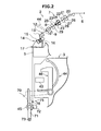
FIG. 2 is a side view of a spinning unit; -
FIG. 3 is a top view of a drafting device; -
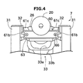
FIG. 4 is a view of the drafting device from an upstream side (from a direction shown by an arrow A inFIG. 3 ); -
FIG. 5 is a side cross-sectional view of the drafting device taken along a line B-B shown inFIG. 3 ; -
FIG. 6A is a side cross-sectional view of a cleaning device; -
FIG. 6B is a drawing showing a schematic shape of protrusions arranged on the cleaning device; -
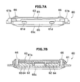
FIG. 7A is a top view of the cleaning device; -
FIG. 7B is a cross-sectional view of the cleaning device; and -
FIG. 8 is a side cross-sectional view of a modification of the drafting device. - Exemplary embodiments of a spinning machine (spinning frame) according to the present invention are explained in detail below with reference to the accompanying drawings. A spinning machine 1 shown in
FIG. 1 includesplural spinning units 2 arranged side by side, ayarn joining carrier 3, amotor box 4, ablower box 80, and amain control device 90. - The
main control device 90 centrally manages all the components of the spinning machine 1, and includes amonitor 91 andinput keys 92. By operating appropriate ones of theinput keys 92, an operator can have the settings and/or status of aspecific spinning unit 2 or all thespinning units 2 displayed on themonitor 91. - As shown in
FIG. 2 , eachspinning unit 2 includes adrafting device 7, aspinning device 9, ayarn pooling device 14, and awinding device 70, sequentially arranged in the mentioned order from upstream to downstream. The terms "upstream" and "downstream" refer to upstream and downstream of a running direction of afiber bundle 8 and aspun yarn 10 during spinning. Each of thespinning units 2 first spins thefiber bundle 8 being conveyed from thedrafting device 7 to form thespun yarn 10 in thespinning device 9, and then winds thespun yarn 10 with thewinding device 70 to form apackage 45. - The
drafting device 7 is arranged in an upper part of ahousing 5 of the spinning machine 1. Thedrafting device 7 drafts a sliver 6 (i.e., stretches a fiber bundle) that is supplied from a not shown sliver case via asliver guide 20 until thesliver 6 attains a predetermined thickness. Thefiber bundle 8 drafted by thedrafting device 7 is supplied to thespinning device 9. The structure and operation of thedrafting device 7 is explained later. - The
spinning device 9 twists thefiber bundle 8 supplied by thedrafting device 7 and forms thespun yarn 10. In the present embodiment, an air-jet spinning device that twists thefiber bundle 8 by using a swirling air current has been used. Concretely, thespinning device 9 includes, though not shown in the drawings or explained in detail in the specification, a fiber guiding member, a swirling air current generating nozzle, and a hollow guide shaft member. The fiber guiding member guides thefiber bundle 8 conveyed from thedrafting device 7 into a spinning chamber formed inside thespinning device 9. The swirling air current generating nozzle is arranged around a path of thefiber bundle 8. Air is blown from the swirling air current generating nozzle to generate a swirling air current inside the spinning chamber. The swirling air current causes the fiber end of thefiber bundle 8 guided into the spinning chamber to be reversed and swirled. The hollow guide shaft member guides the spunyarn 10 from within the spinning chamber to the outside of thespinning device 9. - A yarn
quality measuring device 12 and a spinningsensor 13 are arranged downstream of thespinning device 9. The spunyarn 10 that is spun in thespinning device 9 passes through the yarnquality measuring device 12 and the spinningsensor 13. - The yarn
quality measuring device 12 monitors a thickness of the running spunyarn 10 by using a not shown optical sensor. When a yarn defect (a portion of the spunyarn 10 having an abnormal thickness) is detected, the yarnquality measuring device 12 transmits a yarn defect detection signal to a not shown unit controller. The sensor of the yarnquality measuring device 12 is not limited to the optical sensor; it can be an electrostatic capacitive sensor. Moreover, the yarnquality measuring device 12 can also detect a foreign substance included in the spunyarn 10 as a yarn defect. - The spinning
sensor 13 is arranged immediately downstream of the yarnquality measuring device 12. The spinningsensor 13 detects a tension on the spunyarn 10 in a position between the spinningdevice 9 and theyarn pooling device 14. The spinningsensor 13 transmits a detection signal representing the detected tension to the unit controller. The unit controller detects abnormal portions, such as weak yarn, by monitoring the tension detected by the spinningsensor 13. - The
yarn pooling device 14 is arranged downstream of the yarnquality measuring device 12 and the spinningsensor 13. As shown inFIG. 2 , theyarn pooling device 14 includes ayarn pooling roller 15 and amotor 16 that drives theyarn pooling roller 15 to rotate. - The
yarn pooling roller 15 temporarily pools the spunyarn 10 by winding a certain amount of the spunyarn 10 on an outer peripheral surface thereof. The spunyarn 10 is drawn from thespinning device 9 and conveyed to the downstream side at a predetermined speed by causing theyarn pooling roller 15 to rotate at a predetermined rotational speed with the spunyarn 10 wound on the outer peripheral surface thereof. Because the spunyarn 10 can be temporarily pooled on the outer peripheral surface of theyarn pooling roller 15, theyarn pooling device 14 can be made to function as a kind of buffer. The buffering function of theyarn pooling device 14 avoids troubles (for example, slackening of the spun yarn 10) caused by a mismatch in a spinning speed of thespinning device 9 and a winding speed (the speed of the spunyarn 10 being wound into the package 45) due to some reason. - A
yarn guide 17 and the windingdevice 70 are arranged downstream of theyarn pooling device 14. The windingdevice 70 includes acradle arm 71 that is supported to be swingable about ashaft 73. Thecradle arm 71 rotatably supports abobbin 48 onto which the spunyarn 10 is wound. - The winding
device 70 includes a winding drum (contact roller) 72, atraverse device 75, and a not shown winding drum driving motor. The driving force of the winding drum driving motor is transmitted to the windingdrum 72, causing the windingdrum 72 to rotate in a state of being in contact with an outer peripheral surface of thebobbin 48 or thepackage 45. Thetraverse device 75 includes atraverse guide 76 that is engageable with the spunyarn 10. By driving the windingdrum 72 by the winding drum driving motor while causing thetraverse guide 76 to reciprocate by a not shown driving unit, the windingdevice 70 causes thepackage 45 that is in contact with the windingdrum 72 to rotate, and winds the spunyarn 10 onto thebobbin 48 while traversing the spunyarn 10. - As shown in
FIGS. 1 and2 , theyarn joining carrier 3 includes ayarn joining device 43, asuction pipe 44, and asuction mouth 46. When a yarn breakage or a yarn cut occurs in acertain spinning unit 2, theyarn joining carrier 3 travels over arail 41 up to theparticular spinning unit 2 and then stops. Thesuction pipe 44 swings upward about a shaft, and sucks and catches the spunyarn 10 discharged from thespinning device 9. Then, thesuction pipe 44 swings downward about the shaft to guide the spunyarn 10 to theyarn joining device 43. Thesuction mouth 46 swings downward about a shaft, and sucks and catches the spunyarn 10 from thepackage 45 supported by the windingdevice 70. Then, thesuction mouth 46 swings upward about the shaft to guide the spunyarn 10 to theyarn joining device 43. Theyarn joining device 43 joins the guided spunyarns 10 together. - The structure and the operation of the
drafting device 7 are explained in detail below. First, the structure and the operation of the drafting roller of thedrafting device 7 are explained. - As shown in
FIG. 2 , thedrafting device 7 includes, in addition to the cylindrical sliver guide 20 that guides thesliver 6, drafting roller pairs constituted by opposing bottom rollers (drafting rollers) and top rollers (opposing rollers). The bottom rollers are located on the backside (bottom side) of the spinning machine 1 and the top rollers are located on the front side (top side) of the spinning machine 1. Thedrafting device 7 according to the present embodiment is configured as a so-called four-line drafting device that includes, sequentially from upstream, a back roller pair, a third roller pair, a middle roller pair, and a front roller pair. Hence, the third roller pair corresponds to the drafting roller pair that is the third pair from downstream in a drafting direction. - The top rollers include, sequentially from upstream, a back
top roller 21, a thirdtop roller 22, a middletop roller 24 with anapron belt 23 stretched thereon, and a fronttop roller 25. The bottom rollers include, sequentially from upstream, aback bottom roller 26, a thirdbottom roller 27, amiddle bottom roller 28 with theapron belt 23 stretched thereon, and afront bottom roller 29. - Each of the
top rollers top rollers bottom rollers - The
drafting device 7 includes a not shown urging unit that urges each of thetop rollers bottom rollers top rollers bottom rollers bottom rollers top rollers bottom rollers - The
drafting device 7 conveys thefiber bundle 8 toward the downstream side by nipping thefiber bundle 8 between the rotatingtop rollers bottom rollers drafting device 7, the rotational speed of each drafting roller pair is faster than the rotational speed of the adjacent drafting roller pair on its upstream. Hence, thefiber bundle 8 is stretched (drafted) between adjacent drafting roller pairs, and becomes thinner as it progresses toward the downstream side. - The degree to which the
fiber bundle 8 is drafted can be varied by suitably setting the rotational speed of each of thebottom rollers fiber bundle 8 that has been drafted to the desired thickness can be supplied to thespinning device 9. Accordingly, the spunyarn 10 of a desired yarn count (thickness) can be spun by thespinning device 9. - A structure for cleaning the drafting rollers (concretely, the
back bottom roller 26 and the third bottom roller 27) is explained. An axial direction of the drafting roller is referred to simply as "the axial direction" in the following explanation. InFIGS. 3 and4 , the top rollers have been omitted. - As shown in
FIG. 3 , a drafting roller support base (drafting roller support member) 31 that rotatably supports theback bottom roller 26 and the thirdbottom roller 27 is arranged on each end of theback bottom roller 26 and the thirdbottom roller 27 in the axial direction thereof. - As shown in
FIGS. 3 and4 , astopper 32 is attached onto an upper surface (surface that faces towards the top roller) of the draftingroller support base 31. Thestopper 32 is a metal plate, a part of which is bent at substantially right angle. That is, thestopper 32 has a part that is parallel to the upper surface of the draftingroller support base 31 and a part that is bent downward and is perpendicular to the upper surface. - As shown in
FIG. 5 , asuction device 33 is arranged below the middle bottom roller 28 (on the opposite side of the middle top roller 24). Thesuction device 33 includes asuction port 33a and asuction pipe 33b. Thesuction device 33 is connected to a not shown negative pressure source that generates a suction air current in thesuction port 33a. The suction air current of thesuction device 33 sucks up the fibers removed by acleaning device 60, the fibers that fall during drafting, and the like. The unwanted fibers sucked up by thesuction port 33a are ejected to the outside via thesuction pipe 33b. - In the
drafting device 7, onefiber storing portion 34 is arranged below each of theback bottom roller 26 and the thirdbottom roller 27. Thefiber storing portion 34 has a fiber storing space for temporarily storing the fibers removed by thecleaning device 60, the fibers that fall during drafting, and the like. The unwanted fibers in the fiber storing space are sucked up by thesuction device 33. Alternatively, an operator can manually remove the fibers when the unwanted fibers that are not yet sucked up by thesuction device 33 accumulate to a certain level in the fiber storing space. - One
cleaning device 60 is mounted onto each of theback bottom roller 26 and the thirdbottom roller 27. Because the structure of thecleaning device 60, the manner in which it is mounted, etc., are identical for both theback bottom roller 26 and the thirdbottom roller 27, the following explanation of thecleaning device 60 mounted onto the thirdbottom roller 27 with reference toFIGS. 6A and8 also applies to thecleaning device 60 mounted onto theback bottom roller 26.FIGS. 6A and8 are drawings showing thecleaning device 60 mounted onto the thirdbottom roller 27. Anothercleaning device 60 is similarly mounted onto theback bottom roller 26. Thecleaning device 60 removes fibers and/or oil/grease from the outer peripheral surface of the rotating thirdbottom roller 27 by being in contact with the thirdbottom roller 27. - As shown in
FIG. 6A , thecleaning device 60 includes amagnet case 61, an inner yoke (yoke) 62, an outer yoke (yoke) 63, mountingmagnets 64, and acontact member 65. Thecleaning device 60 is mounted onto the thirdbottom roller 27 by the action of the magnetic force of the mountingmagnets 64. - The
magnet case 61 is made of resin and houses the mountingmagnets 64. Themagnet case 61 is box-shaped with one side (the side where the thirdbottom roller 27 is located and thecontact member 65 is arranged) open. Themagnet case 61 includes abase plate 61a, arms (projecting members) 61b,grip members 61c, and engagingmembers 61d. - The
base plate 61a forms the bottom surface of the box-shapedmagnet case 61. A hole for inserting a screw is formed in thebase plate 61a. - As shown in
FIG. 4 , thearms 61b position thecleaning device 60 by making contact with thestopper 32. Thearms 61b extend in the axial direction on either side of themagnet case 61. - To explain in more detail, the
cleaning device 60 is fixed to the thirdbottom roller 27 by the mountingmagnets 64 and attempts to rotate integrally with the thirdbottom roller 27. By arranging thestopper 32 at a position further downstream than thecleaning device 60 in the rotational direction, the rotation of thecleaning device 60 can be stopped. - With this structure, the
cleaning device 60 removes the fibers adhering to the thirdbottom roller 27 by scraping against the outer peripheral surface thereof. In the present embodiment, thestopper 32 restricts only one surface of thearm 61b. Consequently, even if thecleaning device 60 is arranged, for example, further upstream than thestopper 32 in the rotational direction, thecleaning device 60 rotates with the thirdbottom roller 27, and thereafter is brought to a stop by thestopper 32. In this manner, the proposed structure of thecleaning device 60 according to the present embodiment allows easy attachment of thecleaning device 60. - The
grip members 61c are used by the operator to grip and remove thecleaning device 60 mounted onto the third bottom roller 27 (seeFIG. 4 ). Onegrip member 61c is arranged on one end region (end and its vicinity) and theother grip member 61c is arranged on the other end region (end and its vicinity) in the axial direction (longitudinal direction of the contact member 65). Thegrip members 61c extend upward (toward the top roller) from themagnet case 61. - The two
grip members 61c enable the operator to easily remove thecleaning device 60 even if the magnetic force of the mountingmagnets 64 is strong. Moreover, because thegrip members 61c are arranged on either side of the mid portion (and avoiding the mid portion) in the axial direction, thegrip members 61c can be prevented from coming into contact with thesliver 6 or thefiber bundle 8. - The
inner yoke 62 and theouter yoke 63 function to control the direction in which the magnetic force acts, thereby causing the magnetic force to act more strongly toward the thirdbottom roller 27, and in addition, prevent the magnetic force from acting in other directions. Theouter yoke 63, in particular, prevents leakage of the magnetic force and prevents thecleaning device 60 from adhering to metal components present around thecleaning device 60. As shown inFIG. 6A , theinner yoke 62 has a U-shaped cross-section. The open part of the U-shapedinner yoke 62 faces the thirdbottom roller 27, with theinner yoke 62 arranged on the surface of thebase plate 61a that is on the side of the thirdbottom roller 27. Theouter yoke 63 is a flat plate-shaped member and is arranged on the surface of thebase plate 61a that is on the opposite side of the thirdbottom roller 27 such that theinner yoke 62 and theouter yoke 63 are arranged on either side of thebase plate 61a. In this manner, theinner yoke 62 and theouter yoke 63 cover at least a portion among the plural surfaces of the mountingmagnets 64 except the surface where thecontact member 65 is arranged. - A hole into which a screw (mounting member) 66 can be inserted is formed in each of the
magnet case 61 and theouter yoke 63 at mutually corresponding positions. A screw hole into which thescrew 66 can be fitted is formed in theinner yoke 62 at a position that is aligned with the holes in themagnet case 61 and theouter yoke 63. In a structure in which thecontact member 65, theinner yoke 62, themagnet case 61, and theouter yoke 63 are arranged in this order, by inserting thescrew 66 from the side of theouter yoke 63, with themagnet case 61 sandwiched between theouter yoke 63 and thecontact member 65, theinner yoke 62 and theouter yoke 63 together can be fixed to themagnet case 61. A mounting member other than thescrew 66 can be used for this fixing. - As shown in
FIG. 7B , two mountingmagnets 64 are arranged in thecleaning device 60 on either side of the mid portion in the axial direction (with a gap between the mounting magnets 64). That is, one mountingmagnet 64 is arranged on one side relative to the mid portion of thecleaning device 60 in the axial direction and the other mountingmagnet 64 is arranged on the other side relative to the mid portion of thecleaning device 60 in the axial direction. The mountingmagnets 64 are fixed to the inner yoke 62 (that is, the magnet case 61) with glue (adhesive substance) or an adhesive tape, or such like. The mountingmagnets 64 are covered all around by thecontact member 65 and are therefore not exposed to the outside. Hence, the magnetic forces of the mountingmagnets 64 act via thecontact member 65. Because the mountingmagnets 64 are not arranged at the mid portion of thecleaning device 60 in the axial direction, metal particles do not adhere to the mid portion. Hence, the mid portion of the third bottom roller 27 (where thesliver 6 or thefiber bundle 8 comes into contact) does not get damaged. Thesliver 6 or thefiber bundle 8 does not necessarily pass through the mid portion of the thirdbottom roller 27. If thesliver 6 or thefiber bundle 8 passes through a portion other than the mid portion of the thirdbottom roller 27, the mountingmagnets 64 can be arranged at the portions other than the portion through which thesliver 6 or thefiber bundle 8 passes. - The
contact member 65 is made of resin and functions to remove the fibers adhering to the outer peripheral surface of the thirdbottom roller 27 by being in contact with the thirdbottom roller 27. Thecontact member 65 includes engagingmembers 65a, first protrusions (cleaning members) 65b, and a second protrusion (cleaning member) 65c. - As shown in
FIG. 6A , the engagingmembers 65a of thecontact member 65 are engageable with the engagingmembers 61d of themagnet case 61 through a snap-fit attachment by employing the elasticity of the resin material. In this manner, by having a structure in which thecontact member 65 is attached by a snap-fit attachment and the other components are firmly fixed with thescrew 66, thecontact member 65 can be easily replaced. Consequently, thecontact member 65 can be easily replaced with anothercontact member 65 that is suitable to the winding conditions, etc. - The structure in which the
contact member 65 is attached by a snap-fit attachment and the other components are firmly fixed with thescrew 66 has other advantages as explained below. Because thecontact member 65 and the mountingmagnets 64 are not directly fixed to each other, when thecleaning device 60 is removed from the thirdbottom roller 27, the force acting on the contact member 65 (particularly, the contact portion formed by the engagingmembers contact member 65 can be suppressed, and thereby, life thereof can be prolonged. - As shown in
FIG. 6A , thefirst protrusions 65b and thesecond protrusion 65c protrude toward the third bottom roller 27 (outward from the contact member 65). As shown inFIG. 6B , thefirst protrusions 65b that are located downstream in the rotational direction of the thirdbottom roller 27 are formed on the two ends in the axial direction and not in the mid portion in the axial direction. Thesecond protrusion 65c that is located upstream in the rotational direction of the thirdbottom roller 27 is formed over the entire length in the axial direction. The longitudinal directions of thefirst protrusions 65b and thesecond protrusion 65c match the axial direction (longitudinal direction of the contact member 65). Thefirst protrusions 65b and thesecond protrusion 65c are parallel to each other in the longitudinal direction. - With this structure, during the removal of the unwanted fibers by using the
cleaning device 60, instead of collecting between thefirst protrusions 65b and thesecond protrusion 65c, the unwanted fibers fall outside from the gap between the twofirst protrusions 65b. In this manner, the fibers are prevented from adhering between thefirst protrusions 65b and thesecond protrusion 65c, and the outer peripheral surface of the thirdbottom roller 27. Consequently, maintenance cycle can be prolonged. In thecleaning device 60, the arrangement of the two protrusions (thefirst protrusions 65b and thesecond protrusion 65c) parallel to each other in the axial direction allows thecontact member 65 to be stably pressed against the cylindrical thirdbottom roller 27. - The conventional cleaning device, which is disclosed in Japanese Patent Application Laid-open No.
2006-22443 cleaning device 60 according to the present embodiment that is mounted through the magnetic force can be greatly reduced. Hence, thecleaning device 60 can be arranged outside the fiber storing space. Consequently, a larger fiber storing space can be procured, and hence, the maintenance cycle can be prolonged. Furthermore, as shown inFIG. 6A , when viewed from the axial direction of the thirdbottom roller 27, the size of thecleaning device 60 in the vertical direction and the horizontal direction is smaller than the diameter of the thirdbottom roller 27. - As explained above, the
cleaning device 60 according to the present embodiment includes thecontact member 65 and the mountingmagnets 64. Thecontact member 65 includes thefirst protrusions 65b and thesecond protrusion 65c that come into contact with and clean the outer peripheral surface of the thirdbottom roller 27. The magnetic force of the mountingmagnets 64 acts on the thirdbottom roller 27 via thecontact member 65, and causes thecontact member 65 to come directly into contact with the thirdbottom roller 27. - With this structure, the
contact member 65 is brought firmly into contact with the thirdbottom roller 27 by the action of the magnetic force. Furthermore, the attaching and detaching operations of thecleaning device 60 are simplified. - The
cleaning device 60 according to the present embodiment includes themagnet case 61 that houses the mountingmagnets 64 and that is engageable with thecontact member 65. The mountingmagnets 64 are attached to themagnet case 61 but not to thecontact member 65. - With this structure, during the removal of the
cleaning device 60 from the thirdbottom roller 27, no force is exerted on thecontact member 65. Consequently, thecontact member 65 can be prevented from deforming. - The
drafting device 7 according to the present embodiment includes the draftingroller support base 31 that rotatably supports the thirdbottom roller 27. Thecleaning device 60 includes thearms 61b that project outward in the axial direction of the thirdbottom roller 27. The drafting roller support base 31 (concretely, the stopper 32) positions thecleaning device 60 by coming into contact with thearms 61b (concretely, from among the plural surfaces of thearms 61b, the surface of thearms 61b that lies downstream in the rotational direction of the third bottom roller 27). - With this structure, the attaching and detaching operations of the
cleaning device 60 are made easier. Even if the mounting position of thecleaning device 60 is shifted from its correct position, thecleaning device 60 is moved to the correct position by the rotation of the thirdbottom roller 27. - A modification of the above embodiment is explained below with reference to
FIG. 8 . Parts in the modification that are identical to or similar to the above embodiment are denoted by the same reference numerals and their description is omitted. - In the modification, the shape of the
contact member 65 differs from that of the above embodiment. Concretely, thecontact member 65 according to the modification includes a flat cleaning surface (cleaning member) 65d. Thecontact member 65 according to the modification removes the fibers adhering to the outer peripheral surface of the thirdbottom roller 27 by pressing thecleaning surface 65d against the thirdbottom roller 27. - Exemplary embodiments of the present invention are explained above; however, the structures explained above can be modified as follows.
- The shape of the
contact member 65 can be selected appropriately. For example, contact members with and without protrusions, with various numbers of protrusions, with various shapes of the protrusions, etc., can be prepared and used appropriately depending on the requirement. - The number of the mounting
magnets 64 and their arrangement is not limited, and can be changed to suit the requirement. For example, only one mountingmagnet 64 can be arranged or athird mounting magnet 64 can be arranged even in the mid portion in the axial direction. - The position of the
suction port 33a of thesuction device 33 can be changed to suit the requirement. For example, thesuction port 33a can be arranged below theback bottom roller 26. - The
cleaning device 60 can be mounted at any position peripheral to the drafting roller. In the present embodiment, thecleaning device 60 is mounted on both theback bottom roller 26 and the thirdbottom roller 27. However, because unwanted fibers are more likely to adhere to the thirdbottom roller 27, thecleaning device 60 can be mounted only on the thirdbottom roller 27 and not on theback bottom roller 26. It should be noted that, thecleaning device 60 can be mounted on drafting rollers other than theback bottom roller 26 and the thirdbottom roller 27. - The arrangement of the drafting rollers and the opposing rollers of the
drafting device 7 according the present embodiment is merely an example. The positional relationship between the drafting rollers and the opposing rollers, the number of drafting roller pairs, etc., can be changed to suit the requirement. In an exemplary arrangement, the drafting rollers can be arranged above the top rollers, and the cleaning device can be arranged on the drafting roller. - A cleaning device according to an aspect of the present invention includes a contact member and a mounting magnet. The contact member includes a cleaning member that comes into contact with and cleans an outer peripheral surface of a drafting roller. The mounting magnet brings the contact member into direct contact with the drafting roller by an action of a magnetic force acting on the drafting roller via the contact member.
- With this structure, the contact member is brought firmly into contact with the drafting roller by the magnetic force. Furthermore, the operations of attaching the cleaning device to and detaching the cleaning device from the drafting roller are simplified.
- It is preferable that, the cleaning device further includes a magnet case that houses the mounting magnet and is engageable with the contact member, and the contact member is attachable to and detachable from the mounting magnet or the magnet case.
- With this structure, because contact members of different materials and/or shapes suitable to the winding conditions, etc., can be used, a versatile cleaning device is realized. Even if the contact member is damaged, only the contact member needs to be replaced. Consequently, cost can be reduced.
- It is preferable that, in the cleaning device, the mounting magnet is attached to the magnet case.
- With this structure, during the removal of the cleaning device from the drafting roller, no force is exerted on the contact member (concretely, on the cleaning member). Consequently, the contact member can be prevented from deforming even with repeated attaching and detaching operations.
- It is preferable that, in the cleaning device, the mounting magnet is arranged in plurality with a gap between adjacent mounting magnets.
- With this structure, even if metal particles, etc., get stuck on the surface of the contact member, the part of the drafting roller through which a sliver or a fiber bundle passes can be prevented from being damaged.
- It is preferable that, in the cleaning device, grip members are arranged for an operator to grip the cleaning device with. One grip member is arranged on one end region in a longitudinal direction of the contact member and the other grip member is arranged on the other end region in the longitudinal direction of the contact member.
- By arranging two grip members, the operator can easily grip and remove the cleaning device. The arrangement of the grip members away from the mid portion in the axial direction of the drafting roller prevents the grip members from coming in the way of the fiber bundle that is passing through.
- It is preferable that, in the cleaning device, the cleaning member is a flat surface.
- With this structure, abrasion caused by the cleaning member can be prevented compared to a case where cleaning is performed by protrusions.
- It is preferable that, in the cleaning device, the cleaning member is constituted by at least two protrusions that protrude outward, the at least two protrusions are parallel to each other, and a longitudinal direction of the protrusions and a longitudinal direction of the contact member match.
- With this structure, the fibers adhering to the drafting roller can be easily removed by cleaning the drafting roller by bringing the protrusions into contact with the drafting roller. In particular, by having two parallel protrusions arranged parallel to each other in a longitudinal direction of the contact member, the contact member can be more stably pressed against the drafting roller.
- It is preferable that, in the cleaning device, a yoke is arranged that covers at least, from among plural surfaces of the mounting magnet, a portion of the surfaces other than the surface where the contact member is arranged.
- With this structure, the magnetic force that is used to mount the cleaning device onto the drafting roller can be made stronger, and metal particles can be prevented from adhering around the cleaning device.
- It is preferable that, in the cleaning device, the contact member, the magnet case, and the yoke are arranged in this order, and the yoke is mounted onto the magnet case by inserting a mounting tool from a side of the yoke. The contact member is attached to the magnet case by a snap-fit attachment.
- With this structure, the contact member can be easily replaced and parts other the contact member can be firmly fixed.
- A drafting device according to another aspect of the present invention includes the above cleaning device and a drafting roller pair. The drafting roller pair includes the drafting roller and an opposing roller that is arranged opposed to the drafting roller. The accompanying rotation of the contact member with the rotation of the drafting roller is prevented. The drafting device further includes a suction device that removes, by suction, the fibers removed by the cleaning device.
- With this structure, the contact member is brought firmly into contact with the drafting roller by the magnetic force. Furthermore, the operations of attaching the cleaning device to and detaching the cleaning device from the drafting roller are simplified.
- It is preferable that the drafting device includes a drafting roller support member that rotatably supports the drafting roller. The cleaning device includes a protrusion that protrudes outward with respect to an axial direction of the drafting roller. The cleaning device is positioned by the drafting roller support member being into contact with the protrusion.
- With this structure, the attaching and detaching operations of the cleaning device are made easier. Even if the attachment position of the cleaning device is shifted from the correct position, the cleaning device is moved to the correct position with the rotation of the drafting roller.
- It is preferable that the drafting device includes at least three drafting roller pairs. The cleaning device is arranged on the third drafting roller pair from a downstream side.
- With this structure, because the cleaning device is mounted onto the drafting roller to which unwanted fibers are likely to adhere thereon, the unwanted fibers can be effectively removed.
- It is preferable that the drafting device further includes a fiber storing portion that has a fiber storing space for keeping the fibers removed by the cleaning device. The cleaning device is arranged outside the fiber storing space.
- With this structure, a larger fiber storing space can be procured, and hence, the maintenance cycle can be prolonged.
- A spinning unit according to still another aspect of the present invention includes the above drafting device, a spinning device, and a winding device. The spinning device twists a fiber bundle conveyed from the drafting device and forms a spun yarn. The winding device winds the spun yarn.
- With this structure, in the spinning unit, the contact member can be brought firmly into contact with the drafting roller. Furthermore, in the spinning unit, the operations of attaching the cleaning member to and detaching the cleaning member from the drafting roller are simplified. Particularly, because often several spinning units are arranged side by side, the advantage that the cleaning device can be easily mounted and dismounted is more effectively demonstrated.
Claims (15)
- A cleaning device (60) comprising:a contact member (65) including a cleaning member (65b, 65c; 65d) adapted to be brought into contact with and to clean an outer peripheral surface of a drafting roller (26, 27, 29); anda mounting magnet (64) adapted to bring the contact member (65) into direct contact with the drafting roller (26, 27, 29) by an action of a magnetic force acting on the drafting roller (26, 27, 29) via the contact member (65).
- The cleaning device (60) as claimed in Claim 1, further comprising a magnet case (61) adapted to house the mounting magnet (64) and to be engageable with the contact member (65),
wherein the contact member (65) is adapted to be attachable to and detachable from the mounting magnet (64) or the magnet case (61). - The cleaning device (60) as claimed in Claim 2, wherein the mounting magnet (64) is attached to the magnet case (61).
- The cleaning device (60) as claimed in any one of Claims 1 to 3, wherein the mounting magnet (64) is arranged in plurality with a gap between adjacent mounting magnets (64).
- The cleaning device (60) as claimed in any one of Claims 1 to 4, further comprising a first grip member (61c) and a second grip member (61c) adapted to be gripped by an operator,
wherein the first grip member (61c) is arranged on one end region in a longitudinal direction of the contact member (65) and the second grip member (61c) is arranged on the other end region in the longitudinal direction of the contact member (65). - The cleaning device (60) as claimed in any one of Claims 1 to 5, wherein the cleaning member (65b, 65c; 65d) is a flat surface.
- The cleaning device (60) as claimed in any one of Claims 1 to 5, wherein the cleaning member (65b, 65c; 65d) is constituted by at least two protrusions (65b, 65c) that protrude outward,
the at least two protrusions (65b, 65c) are parallel to each other, and
a longitudinal direction of the protrusions (65b, 65c) and a longitudinal direction of the contact member (65) match. - The cleaning device (60) as claimed in any one of Claims 1 to 7, further comprising a yoke (62) adapted to cover at least, from among plural surfaces of the mounting magnet (64), a portion of the surfaces other than the surface where the contact member (65) is arranged.
- The cleaning device (60) as claimed in Claim 8, wherein the contact member (65), the magnet case (61), and the yoke (62) are arranged in this order, and the yoke (62) is mounted onto the magnet case (61) by inserting a mounting member (66) from a side of the yoke (62), and
the contact member (65) is attached to the magnet case (61) by a snap-fit attachment. - A drafting device (7) comprising:the cleaning device (60) as claimed in any one of Claims 1 to 9; anda drafting roller pair including the drafting roller (26, 27, 29) and an opposing roller (21, 22, 25) that is arranged opposed to the drafting roller (26, 27, 29),wherein accompanying rotation of the contact member (65) with rotation of the drafting roller (26, 27, 29) is prevented.
- The drafting device (7) as claimed in Claim 10, further comprising a suction device (33) adapted to remove, by suction, fibers removed by the cleaning device (60).
- The drafting device (7) as claimed in Claim 10 or 11, further comprising a drafting roller support member (31) adapted to rotatably support the drafting roller (26, 27, 29),
wherein the cleaning device (60) includes a protrusion (61b) that protrudes outward with respect to an axial direction of the drafting roller (26, 27, 29), and
the cleaning device (60) is adapted to be positioned by the drafting roller support member (31) being into contact with the protrusion (61b). - The drafting device (7) as claimed in any one of Claims 10 to 12, comprising at least three drafting roller pairs,
wherein the cleaning device (60) is arranged on a third drafting roller pair (22, 27) from a downstream side in a drafting direction. - The drafting device (7) as claimed in any one of Claims 10 to 13, further comprising a fiber storing portion (34) having a fiber storing space adapted to keep fibers removed by the cleaning device (60),
wherein the cleaning device (60) is arranged outside the fiber storing space. - A spinning unit (2) comprising:the drafting device (7) as claimed in any one of Claims 10 to 14;a spinning device (9) adapted to twist a fiber bundle (8) conveyed from the drafting device (7) and form a spun yarn (10); anda winding device (70) adapted to wind the spun yarn (10).
Applications Claiming Priority (1)
| Application Number | Priority Date | Filing Date | Title |
|---|---|---|---|
| JP2013241301A JP2015101797A (en) | 2013-11-21 | 2013-11-21 | Cleaning device, draft device and spinning unit |
Publications (2)
| Publication Number | Publication Date |
|---|---|
| EP2876193A1 true EP2876193A1 (en) | 2015-05-27 |
| EP2876193B1 EP2876193B1 (en) | 2017-07-05 |
Family
ID=51842381
Family Applications (1)
| Application Number | Title | Priority Date | Filing Date |
|---|---|---|---|
| EP14190657.8A Not-in-force EP2876193B1 (en) | 2013-11-21 | 2014-10-28 | Cleaning device, drafting device, and spinning unit |
Country Status (3)
| Country | Link |
|---|---|
| EP (1) | EP2876193B1 (en) |
| JP (1) | JP2015101797A (en) |
| CN (2) | CN204644540U (en) |
Cited By (2)
| Publication number | Priority date | Publication date | Assignee | Title |
|---|---|---|---|---|
| EP3260585A1 (en) * | 2016-06-24 | 2017-12-27 | Murata Machinery, Ltd. | Cleaning device for drafting roller |
| CN107938043A (en) * | 2018-01-02 | 2018-04-20 | 江阴市华方新技术科研有限公司 | The cleaning device of carry-over pinch rolls |
Families Citing this family (4)
| Publication number | Priority date | Publication date | Assignee | Title |
|---|---|---|---|---|
| JP2015101797A (en) * | 2013-11-21 | 2015-06-04 | 村田機械株式会社 | Cleaning device, draft device and spinning unit |
| JP6475669B2 (en) | 2016-07-13 | 2019-02-27 | 矢崎総業株式会社 | connector |
| DE102021107791A1 (en) * | 2021-03-29 | 2022-09-29 | Saurer Spinning Solutions Gmbh & Co. Kg | Device and method for carrying out cleaning of a cop tube arranged on a arbor of a movable carrier of a cop and tube transport system |
| CN113388934B (en) * | 2021-06-03 | 2022-04-29 | 东台市润生纺机专件有限公司 | High-precision roller for double-core-spun yarn |
Citations (5)
| Publication number | Priority date | Publication date | Assignee | Title |
|---|---|---|---|---|
| GB909073A (en) * | 1959-06-13 | 1962-10-24 | Ferdinand Reiterer | Improvements in cleaning devices for machines for treating fibrous products |
| US3101504A (en) * | 1959-09-12 | 1963-08-27 | Luwa Ag | Cleaning device for yarn carrying rotary cylinders of textile machines |
| JPS6324279U (en) * | 1986-07-28 | 1988-02-17 | ||
| JPH1077529A (en) * | 1996-09-05 | 1998-03-24 | Toyota Autom Loom Works Ltd | Apparatus for preventing magnet type clearer roller from dropping in spinning machine and tool for preventing dropping |
| JP2006022443A (en) | 2004-07-09 | 2006-01-26 | Murata Mach Ltd | Cleaning apparatus for draft roller |
Family Cites Families (4)
| Publication number | Priority date | Publication date | Assignee | Title |
|---|---|---|---|---|
| JPH08187469A (en) * | 1995-01-10 | 1996-07-23 | Toray Ind Inc | Roller cleaning device |
| JPH0978364A (en) * | 1995-09-14 | 1997-03-25 | Toray Ind Inc | Roller cleaning scraper device |
| JP2013067871A (en) * | 2011-09-20 | 2013-04-18 | Murata Mach Ltd | Draft device and spinning machine |
| JP2015101797A (en) * | 2013-11-21 | 2015-06-04 | 村田機械株式会社 | Cleaning device, draft device and spinning unit |
-
2013
- 2013-11-21 JP JP2013241301A patent/JP2015101797A/en active Pending
-
2014
- 2014-10-28 EP EP14190657.8A patent/EP2876193B1/en not_active Not-in-force
- 2014-11-03 CN CN201420648512.4U patent/CN204644540U/en not_active Withdrawn - After Issue
- 2014-11-03 CN CN201410608247.1A patent/CN104651990B/en active Active
Patent Citations (5)
| Publication number | Priority date | Publication date | Assignee | Title |
|---|---|---|---|---|
| GB909073A (en) * | 1959-06-13 | 1962-10-24 | Ferdinand Reiterer | Improvements in cleaning devices for machines for treating fibrous products |
| US3101504A (en) * | 1959-09-12 | 1963-08-27 | Luwa Ag | Cleaning device for yarn carrying rotary cylinders of textile machines |
| JPS6324279U (en) * | 1986-07-28 | 1988-02-17 | ||
| JPH1077529A (en) * | 1996-09-05 | 1998-03-24 | Toyota Autom Loom Works Ltd | Apparatus for preventing magnet type clearer roller from dropping in spinning machine and tool for preventing dropping |
| JP2006022443A (en) | 2004-07-09 | 2006-01-26 | Murata Mach Ltd | Cleaning apparatus for draft roller |
Cited By (2)
| Publication number | Priority date | Publication date | Assignee | Title |
|---|---|---|---|---|
| EP3260585A1 (en) * | 2016-06-24 | 2017-12-27 | Murata Machinery, Ltd. | Cleaning device for drafting roller |
| CN107938043A (en) * | 2018-01-02 | 2018-04-20 | 江阴市华方新技术科研有限公司 | The cleaning device of carry-over pinch rolls |
Also Published As
| Publication number | Publication date |
|---|---|
| CN204644540U (en) | 2015-09-16 |
| CN104651990B (en) | 2019-04-09 |
| EP2876193B1 (en) | 2017-07-05 |
| CN104651990A (en) | 2015-05-27 |
| JP2015101797A (en) | 2015-06-04 |
Similar Documents
| Publication | Publication Date | Title |
|---|---|---|
| EP2876193B1 (en) | Cleaning device, drafting device, and spinning unit | |
| EP2573226B1 (en) | Draft device and spinning machine | |
| JP2013049932A (en) | Spinning machine | |
| CN210104152U (en) | Spinning machine | |
| CN106048789B (en) | Drafting device and spinning machine | |
| EP2671982A1 (en) | Spinning machine | |
| JP2013160678A (en) | Fiber strand monitoring device, winding unit, and yarn winder | |
| CN104828649A (en) | Yarn catching device and yarn winding machine | |
| JP2016188444A (en) | Cleaning device, draft machine, and spinning machine | |
| CN108977945B (en) | Roller unit, draft device, and spinning machine | |
| EP2921577B1 (en) | Draft device and spinning machine | |
| EP2921578A2 (en) | Belt guide roller, cleaning device, draft device, and spinning machine | |
| EP3026152B1 (en) | Fiber collecting device, drafting device, and spinning machine | |
| CN107541819B (en) | Cleaning device for drafting roller and drafting device | |
| CN105793479B (en) | Fiber discharger and weaving loom | |
| EP3037374A1 (en) | Textile machine | |
| EP1726695A1 (en) | Core yarn production method and apparatus | |
| CN112831869B (en) | Cleaning device, drafting device and spinning machine | |
| EP2966199B1 (en) | Spinning machine and spinning method | |
| JP2020133037A (en) | Cover for draft machine, draft machine and spinning machine | |
| JP2023183564A (en) | spinning machine | |
| JP2015067440A (en) | Textile machine | |
| JP2020134245A (en) | Yarn tension detecting device and winding unit |
Legal Events
| Date | Code | Title | Description |
|---|---|---|---|
| PUAI | Public reference made under article 153(3) epc to a published international application that has entered the european phase |
Free format text: ORIGINAL CODE: 0009012 |
|
| 17P | Request for examination filed |
Effective date: 20141028 |
|
| AK | Designated contracting states |
Kind code of ref document: A1 Designated state(s): AL AT BE BG CH CY CZ DE DK EE ES FI FR GB GR HR HU IE IS IT LI LT LU LV MC MK MT NL NO PL PT RO RS SE SI SK SM TR |
|
| AX | Request for extension of the european patent |
Extension state: BA ME |
|
| R17P | Request for examination filed (corrected) |
Effective date: 20151022 |
|
| RBV | Designated contracting states (corrected) |
Designated state(s): AL AT BE BG CH CY CZ DE DK EE ES FI FR GB GR HR HU IE IS IT LI LT LU LV MC MK MT NL NO PL PT RO RS SE SI SK SM TR |
|
| GRAP | Despatch of communication of intention to grant a patent |
Free format text: ORIGINAL CODE: EPIDOSNIGR1 |
|
| INTG | Intention to grant announced |
Effective date: 20161111 |
|
| GRAJ | Information related to disapproval of communication of intention to grant by the applicant or resumption of examination proceedings by the epo deleted |
Free format text: ORIGINAL CODE: EPIDOSDIGR1 |
|
| INTC | Intention to grant announced (deleted) | ||
| GRAP | Despatch of communication of intention to grant a patent |
Free format text: ORIGINAL CODE: EPIDOSNIGR1 |
|
| INTG | Intention to grant announced |
Effective date: 20170301 |
|
| GRAS | Grant fee paid |
Free format text: ORIGINAL CODE: EPIDOSNIGR3 |
|
| GRAA | (expected) grant |
Free format text: ORIGINAL CODE: 0009210 |
|
| AK | Designated contracting states |
Kind code of ref document: B1 Designated state(s): AL AT BE BG CH CY CZ DE DK EE ES FI FR GB GR HR HU IE IS IT LI LT LU LV MC MK MT NL NO PL PT RO RS SE SI SK SM TR |
|
| REG | Reference to a national code |
Ref country code: GB Ref legal event code: FG4D |
|
| REG | Reference to a national code |
Ref country code: CH Ref legal event code: EP |
|
| REG | Reference to a national code |
Ref country code: AT Ref legal event code: REF Ref document number: 906680 Country of ref document: AT Kind code of ref document: T Effective date: 20170715 |
|
| REG | Reference to a national code |
Ref country code: IE Ref legal event code: FG4D |
|
| REG | Reference to a national code |
Ref country code: DE Ref legal event code: R096 Ref document number: 602014011441 Country of ref document: DE |
|
| REG | Reference to a national code |
Ref country code: NL Ref legal event code: MP Effective date: 20170705 |
|
| REG | Reference to a national code |
Ref country code: AT Ref legal event code: MK05 Ref document number: 906680 Country of ref document: AT Kind code of ref document: T Effective date: 20170705 |
|
| REG | Reference to a national code |
Ref country code: LT Ref legal event code: MG4D |
|
| PG25 | Lapsed in a contracting state [announced via postgrant information from national office to epo] |
Ref country code: HR Free format text: LAPSE BECAUSE OF FAILURE TO SUBMIT A TRANSLATION OF THE DESCRIPTION OR TO PAY THE FEE WITHIN THE PRESCRIBED TIME-LIMIT Effective date: 20170705 Ref country code: NO Free format text: LAPSE BECAUSE OF FAILURE TO SUBMIT A TRANSLATION OF THE DESCRIPTION OR TO PAY THE FEE WITHIN THE PRESCRIBED TIME-LIMIT Effective date: 20171005 Ref country code: FI Free format text: LAPSE BECAUSE OF FAILURE TO SUBMIT A TRANSLATION OF THE DESCRIPTION OR TO PAY THE FEE WITHIN THE PRESCRIBED TIME-LIMIT Effective date: 20170705 Ref country code: AT Free format text: LAPSE BECAUSE OF FAILURE TO SUBMIT A TRANSLATION OF THE DESCRIPTION OR TO PAY THE FEE WITHIN THE PRESCRIBED TIME-LIMIT Effective date: 20170705 Ref country code: NL Free format text: LAPSE BECAUSE OF FAILURE TO SUBMIT A TRANSLATION OF THE DESCRIPTION OR TO PAY THE FEE WITHIN THE PRESCRIBED TIME-LIMIT Effective date: 20170705 Ref country code: SE Free format text: LAPSE BECAUSE OF FAILURE TO SUBMIT A TRANSLATION OF THE DESCRIPTION OR TO PAY THE FEE WITHIN THE PRESCRIBED TIME-LIMIT Effective date: 20170705 Ref country code: LT Free format text: LAPSE BECAUSE OF FAILURE TO SUBMIT A TRANSLATION OF THE DESCRIPTION OR TO PAY THE FEE WITHIN THE PRESCRIBED TIME-LIMIT Effective date: 20170705 |
|
| PG25 | Lapsed in a contracting state [announced via postgrant information from national office to epo] |
Ref country code: IS Free format text: LAPSE BECAUSE OF FAILURE TO SUBMIT A TRANSLATION OF THE DESCRIPTION OR TO PAY THE FEE WITHIN THE PRESCRIBED TIME-LIMIT Effective date: 20171105 Ref country code: LV Free format text: LAPSE BECAUSE OF FAILURE TO SUBMIT A TRANSLATION OF THE DESCRIPTION OR TO PAY THE FEE WITHIN THE PRESCRIBED TIME-LIMIT Effective date: 20170705 Ref country code: ES Free format text: LAPSE BECAUSE OF FAILURE TO SUBMIT A TRANSLATION OF THE DESCRIPTION OR TO PAY THE FEE WITHIN THE PRESCRIBED TIME-LIMIT Effective date: 20170705 Ref country code: RS Free format text: LAPSE BECAUSE OF FAILURE TO SUBMIT A TRANSLATION OF THE DESCRIPTION OR TO PAY THE FEE WITHIN THE PRESCRIBED TIME-LIMIT Effective date: 20170705 Ref country code: GR Free format text: LAPSE BECAUSE OF FAILURE TO SUBMIT A TRANSLATION OF THE DESCRIPTION OR TO PAY THE FEE WITHIN THE PRESCRIBED TIME-LIMIT Effective date: 20171006 Ref country code: PL Free format text: LAPSE BECAUSE OF FAILURE TO SUBMIT A TRANSLATION OF THE DESCRIPTION OR TO PAY THE FEE WITHIN THE PRESCRIBED TIME-LIMIT Effective date: 20170705 Ref country code: BG Free format text: LAPSE BECAUSE OF FAILURE TO SUBMIT A TRANSLATION OF THE DESCRIPTION OR TO PAY THE FEE WITHIN THE PRESCRIBED TIME-LIMIT Effective date: 20171005 |
|
| REG | Reference to a national code |
Ref country code: DE Ref legal event code: R097 Ref document number: 602014011441 Country of ref document: DE |
|
| PG25 | Lapsed in a contracting state [announced via postgrant information from national office to epo] |
Ref country code: RO Free format text: LAPSE BECAUSE OF FAILURE TO SUBMIT A TRANSLATION OF THE DESCRIPTION OR TO PAY THE FEE WITHIN THE PRESCRIBED TIME-LIMIT Effective date: 20170705 Ref country code: DK Free format text: LAPSE BECAUSE OF FAILURE TO SUBMIT A TRANSLATION OF THE DESCRIPTION OR TO PAY THE FEE WITHIN THE PRESCRIBED TIME-LIMIT Effective date: 20170705 |
|
| PLBE | No opposition filed within time limit |
Free format text: ORIGINAL CODE: 0009261 |
|
| STAA | Information on the status of an ep patent application or granted ep patent |
Free format text: STATUS: NO OPPOSITION FILED WITHIN TIME LIMIT |
|
| PG25 | Lapsed in a contracting state [announced via postgrant information from national office to epo] |
Ref country code: SM Free format text: LAPSE BECAUSE OF FAILURE TO SUBMIT A TRANSLATION OF THE DESCRIPTION OR TO PAY THE FEE WITHIN THE PRESCRIBED TIME-LIMIT Effective date: 20170705 Ref country code: SK Free format text: LAPSE BECAUSE OF FAILURE TO SUBMIT A TRANSLATION OF THE DESCRIPTION OR TO PAY THE FEE WITHIN THE PRESCRIBED TIME-LIMIT Effective date: 20170705 Ref country code: IT Free format text: LAPSE BECAUSE OF FAILURE TO SUBMIT A TRANSLATION OF THE DESCRIPTION OR TO PAY THE FEE WITHIN THE PRESCRIBED TIME-LIMIT Effective date: 20170705 Ref country code: MC Free format text: LAPSE BECAUSE OF FAILURE TO SUBMIT A TRANSLATION OF THE DESCRIPTION OR TO PAY THE FEE WITHIN THE PRESCRIBED TIME-LIMIT Effective date: 20170705 Ref country code: EE Free format text: LAPSE BECAUSE OF FAILURE TO SUBMIT A TRANSLATION OF THE DESCRIPTION OR TO PAY THE FEE WITHIN THE PRESCRIBED TIME-LIMIT Effective date: 20170705 |
|
| 26N | No opposition filed |
Effective date: 20180406 |
|
| REG | Reference to a national code |
Ref country code: IE Ref legal event code: MM4A |
|
| REG | Reference to a national code |
Ref country code: FR Ref legal event code: ST Effective date: 20180629 |
|
| PG25 | Lapsed in a contracting state [announced via postgrant information from national office to epo] |
Ref country code: LU Free format text: LAPSE BECAUSE OF NON-PAYMENT OF DUE FEES Effective date: 20171028 |
|
| REG | Reference to a national code |
Ref country code: BE Ref legal event code: MM Effective date: 20171031 |
|
| PG25 | Lapsed in a contracting state [announced via postgrant information from national office to epo] |
Ref country code: SI Free format text: LAPSE BECAUSE OF FAILURE TO SUBMIT A TRANSLATION OF THE DESCRIPTION OR TO PAY THE FEE WITHIN THE PRESCRIBED TIME-LIMIT Effective date: 20170705 Ref country code: BE Free format text: LAPSE BECAUSE OF NON-PAYMENT OF DUE FEES Effective date: 20171031 Ref country code: FR Free format text: LAPSE BECAUSE OF NON-PAYMENT OF DUE FEES Effective date: 20171031 |
|
| PG25 | Lapsed in a contracting state [announced via postgrant information from national office to epo] |
Ref country code: MT Free format text: LAPSE BECAUSE OF NON-PAYMENT OF DUE FEES Effective date: 20171028 |
|
| PG25 | Lapsed in a contracting state [announced via postgrant information from national office to epo] |
Ref country code: IE Free format text: LAPSE BECAUSE OF NON-PAYMENT OF DUE FEES Effective date: 20171028 |
|
| GBPC | Gb: european patent ceased through non-payment of renewal fee |
Effective date: 20181028 |
|
| PG25 | Lapsed in a contracting state [announced via postgrant information from national office to epo] |
Ref country code: HU Free format text: LAPSE BECAUSE OF FAILURE TO SUBMIT A TRANSLATION OF THE DESCRIPTION OR TO PAY THE FEE WITHIN THE PRESCRIBED TIME-LIMIT; INVALID AB INITIO Effective date: 20141028 |
|
| PG25 | Lapsed in a contracting state [announced via postgrant information from national office to epo] |
Ref country code: CY Free format text: LAPSE BECAUSE OF FAILURE TO SUBMIT A TRANSLATION OF THE DESCRIPTION OR TO PAY THE FEE WITHIN THE PRESCRIBED TIME-LIMIT Effective date: 20170705 Ref country code: GB Free format text: LAPSE BECAUSE OF NON-PAYMENT OF DUE FEES Effective date: 20181028 |
|
| PGFP | Annual fee paid to national office [announced via postgrant information from national office to epo] |
Ref country code: CZ Payment date: 20190925 Year of fee payment: 6 |
|
| PG25 | Lapsed in a contracting state [announced via postgrant information from national office to epo] |
Ref country code: MK Free format text: LAPSE BECAUSE OF FAILURE TO SUBMIT A TRANSLATION OF THE DESCRIPTION OR TO PAY THE FEE WITHIN THE PRESCRIBED TIME-LIMIT Effective date: 20170705 |
|
| PGFP | Annual fee paid to national office [announced via postgrant information from national office to epo] |
Ref country code: DE Payment date: 20191021 Year of fee payment: 6 |
|
| PG25 | Lapsed in a contracting state [announced via postgrant information from national office to epo] |
Ref country code: TR Free format text: LAPSE BECAUSE OF FAILURE TO SUBMIT A TRANSLATION OF THE DESCRIPTION OR TO PAY THE FEE WITHIN THE PRESCRIBED TIME-LIMIT Effective date: 20170705 |
|
| PGFP | Annual fee paid to national office [announced via postgrant information from national office to epo] |
Ref country code: CH Payment date: 20191021 Year of fee payment: 6 |
|
| PG25 | Lapsed in a contracting state [announced via postgrant information from national office to epo] |
Ref country code: PT Free format text: LAPSE BECAUSE OF FAILURE TO SUBMIT A TRANSLATION OF THE DESCRIPTION OR TO PAY THE FEE WITHIN THE PRESCRIBED TIME-LIMIT Effective date: 20170705 |
|
| PG25 | Lapsed in a contracting state [announced via postgrant information from national office to epo] |
Ref country code: AL Free format text: LAPSE BECAUSE OF FAILURE TO SUBMIT A TRANSLATION OF THE DESCRIPTION OR TO PAY THE FEE WITHIN THE PRESCRIBED TIME-LIMIT Effective date: 20170705 |
|
| REG | Reference to a national code |
Ref country code: DE Ref legal event code: R119 Ref document number: 602014011441 Country of ref document: DE |
|
| REG | Reference to a national code |
Ref country code: CH Ref legal event code: PL |
|
| PG25 | Lapsed in a contracting state [announced via postgrant information from national office to epo] |
Ref country code: CZ Free format text: LAPSE BECAUSE OF NON-PAYMENT OF DUE FEES Effective date: 20201028 Ref country code: DE Free format text: LAPSE BECAUSE OF NON-PAYMENT OF DUE FEES Effective date: 20210501 |
|
| PG25 | Lapsed in a contracting state [announced via postgrant information from national office to epo] |
Ref country code: CH Free format text: LAPSE BECAUSE OF NON-PAYMENT OF DUE FEES Effective date: 20201031 Ref country code: LI Free format text: LAPSE BECAUSE OF NON-PAYMENT OF DUE FEES Effective date: 20201031 |