EP2875751B1 - Tool for cleaning surfaces - Google Patents
Tool for cleaning surfaces Download PDFInfo
- Publication number
- EP2875751B1 EP2875751B1 EP14198348.6A EP14198348A EP2875751B1 EP 2875751 B1 EP2875751 B1 EP 2875751B1 EP 14198348 A EP14198348 A EP 14198348A EP 2875751 B1 EP2875751 B1 EP 2875751B1
- Authority
- EP
- European Patent Office
- Prior art keywords
- coupling
- attachment element
- handle
- attachment
- tool according
- Prior art date
- Legal status (The legal status is an assumption and is not a legal conclusion. Google has not performed a legal analysis and makes no representation as to the accuracy of the status listed.)
- Active
Links
Images




Classifications
-
- A—HUMAN NECESSITIES
- A46—BRUSHWARE
- A46B—BRUSHES
- A46B5/00—Brush bodies; Handles integral with brushware
- A46B5/002—Brush bodies; Handles integral with brushware having articulations, joints or flexible portions
- A46B5/0054—Brush bodies; Handles integral with brushware having articulations, joints or flexible portions designed to allow relative positioning of the head to body
- A46B5/0058—Mechanical joint or hinge made up of several components
-
- A—HUMAN NECESSITIES
- A46—BRUSHWARE
- A46B—BRUSHES
- A46B5/00—Brush bodies; Handles integral with brushware
- A46B5/002—Brush bodies; Handles integral with brushware having articulations, joints or flexible portions
- A46B5/0054—Brush bodies; Handles integral with brushware having articulations, joints or flexible portions designed to allow relative positioning of the head to body
- A46B5/0075—Brush bodies; Handles integral with brushware having articulations, joints or flexible portions designed to allow relative positioning of the head to body being adjustable and stable during use
- A46B5/0083—Mechanical joint allowing adjustment in at least one plane
-
- A—HUMAN NECESSITIES
- A46—BRUSHWARE
- A46B—BRUSHES
- A46B7/00—Bristle carriers arranged in the brush body
- A46B7/04—Bristle carriers arranged in the brush body interchangeably removable bristle carriers
-
- A—HUMAN NECESSITIES
- A46—BRUSHWARE
- A46B—BRUSHES
- A46B2200/00—Brushes characterized by their functions, uses or applications
- A46B2200/30—Brushes for cleaning or polishing
- A46B2200/302—Broom
Definitions
- the present invention relates to a tool for cleaning surfaces, in particular indoor and outdoor floors.
- tools for cleaning surfaces in particular floors, such as, for example, brooms
- floors such as, for example, brooms
- the bristles may consist of threads made of plastics, or other material, for example at a maximum tilt of 30o in relation to the supporting plate and with a maximum axial length of 15 centimetres. This tilt is made along the longitudinal axis of the supporting plate.
- the main drawback which is encountered above all in brooms for cleaning large surfaces, consists of the great stress to which the user is subject when he uses the broom. In fact, in use, the user grips the handle with both hands and to these all the mechanical stress is transmitted that arises from the friction between the bristles and the floor affected by cleaning.
- a further drawback that is found in the aforesaid brooms derives from the system for fixing the handle to the aforesaid plate.
- the end portion of the handle intended to be fixed to the plate is deformed so as to take on a substantially flat configuration. It appears obvious that such a deformation operation is not only expensive but causes less mechanical resistance of the handle with a consequent great risk of breakage of the handle at the deformed end.
- brooms comprise a supporting element of the bristles and a handle connected to said supporting element by damping means suitable for damping mechanical stress transmitted along said handle.
- Brooms are further known that comprise: a supporting element of the bristles, a coupling element that extends from a surface of the supporting element, and a handle connected to the coupling element, with an axial end portion of said handle that is associated with connecting means suitable for connecting said axial end portion of said handle to said coupling element.
- the position of the handle in relation to the supporting plate of the bristles is substantially fixed, which makes the use of the tool inconvenient, in particular when portions of surfaces have to be cleaned that, in order to be reached easily, would require the tilt of the handle to be modified in relation to the supporting plate of the bristles.
- EP 1782712 discloses a tool for cleaning surfaces having a casing wherein is mounted, with the possibility of upwards and downwards displacement, a plate holding the corresponding bristles that emerge from the orifices (6) of a grille fixed on the lower edge of the casing.
- the tool further comprises an attachment element on which the corresponding handle is mounted, the attachment element being provided with means of connection to the bristle support plate, with the possibility of rotation with respect thereto, and with positioning means in cavities or indentations of the casing to hold a vertical or inclined position the attachment element and, therefore, a position of maximum lowering of the plate or maximum raising thereof, so that the bristles totally or partially emerge through the grille to form a brush with long bristles or a brush with shorter bristles.
- a tool for cleaning surfaces comprising a supporting element that holds a plurality of bristles, or groups of bristles and a handle for gripping and manoeuvring said tool, characterised in that it further comprises a coupling element that can be connected removably to said supporting element and to which said handle (106) can be removably connected.
- the tool according to the invention enables the supporting element of the bristles to be replaced simply and rapidly when the latter are worn.
- an attachment element to which said handle is fixable in a movable manner, said attachment element having an angular position that is adjustable in relation to said coupling element.
- damping means is provided between said handle and said attachment element, to damp and/or absorb possible anomalous stress, arising, for example, from blows of the supporting element of the bristles against obstacles whilst the tool is used.
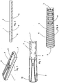
- FIGS 1 to 4 there is shown a supporting element for bristles 1 of a tool for cleaning surfaces according to the invention, which is configured to be coupled simply and rapidly with a coupling element, which will be disclosed below, intended for receiving a handle for gripping and moving the tool.
- the support for bristles 1 is provided, in a first face 2 intended for receiving said coupling element, with a seat 3 intended to be coupled with said coupling element; the seat 3 is provided with a series of protrusions 4 suitable for preventing movements of the coupling element in a direction that is perpendicular to the supporting element 1.
- a second face 5 of the supporting element 1 opposite the first face 2 is provided with a plurality of grooves 6 intended for receiving groups of bristles for removing dust and other solid substances from surfaces, said bristles being made, for example, of plastics or other materials, also of natural origin.
- the grooves 6 preferably have a circumference arc configuration.
- a hole 7 intended for receiving a fixing element 34a ( Figure 15 ), for example a screw, or other suitable fixing means, for fixing the coupling element to the supporting element 1. It is advantageous for the width of the supporting element 1 to increase progressively to a front end 2a thereof. This makes the tool cleaning action more effective.
- FIGS 5 to 8 there is shown a first embodiment of a coupling element 8, which does not form part of the present invention, suitable for coupling with the supporting element 1; the coupling element 8 is intended for coupling with a gripping element, for example a handle, by means of which it is possible to grip and handle the tool according to the invention, to remove dust or other dirt from a surface.
- a gripping element for example a handle
- the coupling element 8 comprises a body 9 provided with a base 10 suitable for being slidingly inserted into the seat 3 of the supporting element 1.
- the base 10 is provided peripherally with a groove 11 intended for coupling with the protrusions 4 of the supporting element 1, so that movements of the coupling element 8 are prevented in a direction that is perpendicular to the seat 3 of the supporting element 1.
- the coupling element 8 comprises an attachment element 12 on which said handle can be inserted and fixed.
- the attachment element 12 is preferably tilted by an angle ⁇ in relation to a perpendicular to the base 10, the angle ⁇ being preferably comprised between approximately 15° and approximately 30°.
- the attachment element 12 is provided with a shank 13 intended to be inserted into a hollow end of said handle.
- the shank 13 is provided with two through holes 14 and 15 intended for receiving the stem of a respective bolt for coupling and fixing said handle to the shank 13.
- a respective end 14a, 15a of said through holes is shaped so as to receive the nut of the bolt; the shaped ends 14a, 15a are made on opposite sides of the shank 13 so that the handle of the tool can be mounted only on a preset angular position on the shank 13, which is particularly advantageous in the case of a handle with an ergonomic shape, to prevent the handle being mounted in an incorrect position.
- FIG. 8 to 10 there is shown a second embodiment of a coupling element 8 in which the body 9 is provided with a cradle element 17 intended for coupling with an angularly movable attachment element, for example the attachment element 18 in Figure 11 , which will be disclosed in detail below.
- protrusions 19 On the bottom of the cradle 17 there are provided protrusions 19, for example in the form of toothing that is intended for fixing the angular position of the angularly movable attachment element.
- the cradle 17 is provided with side walls 20 in each of which there is provided a respective through hole 21 intended for receiving a pivot 22 ( Figure 18 ) that constitutes the rotation axis of the attachment element in relation to the cradle 17.
- the bottom of the cradle 17 with the protrusions 19 can be made of an interchangeable insert, for example made of a material with great resistance to wear.
- a respective slot 23 is further made through which a locking element 24 can be inserted ( Figure 14 ) that is coupled with the attachment element 18 to lock the angular position thereof in relation to the cradle 17.
- FIGS 11 to 13 there is shown the attachment element 18 that comprises a body 25 provided above with a shank 13 intended for coupling with said handle.
- two through holes 14 and 15 are made that are intended for receiving the stem of a respective bolt for fixing said handle to the shank 13.
- a respective end 14a, 15a of said through holes is shaped so as to receive the nut of the bolt; the shaped ends 14a, 15a are made on opposite sides of the shank 13, to enable mounting of the handle in a predefined angular position in relation to the shank 13, as mentioned before.
- a through hole 26 intended for receiving the pivot 22 that constitutes the rotation axis of the attachment element 18 in relation to the cradle 17 of the coupling element 8.
- a seat 27 intended for receiving a positioning element 28 ( Figures 16 a , 16 b ) intended for coupling with the protrusions 19 obtained on the bottom of the cradle 17 of the coupling element 8 to determine the angular position of the attachment element 18 in relation to the cradle 17.
- the positioning element 28 comprises a body 29 in the lower face of which there are obtained protrusions 30, for example in the shape of toothing, shaped so as to couple with the protrusions 19 of the cradle 17 to determine the angular positioning of the attachment element 18 in the cradle 17.
- the body 29 can move in the seat 27 guided by the walls of the seat.
- the body 29 is provided with a slot 31 that can be used for the passage of the locking element 24, if it is present.
- the movement of the body 29 is contrasted by an elastic element 32, for example a coil spring wound around an upper protrusion 33 of the body 29 and compressed between the body 29 and a bottom wall 34 of the seat 27.
- the walls of the seat 27 enable the positioning element 28 to move in a direction substantially perpendicular to the bottom of the cradle 17, so that the protrusions 30 disengage from the protrusions 19 of the cradle 17 to enable the angular position of the attachment element 18 to be modified.
- the locking element 24 is optional inasmuch as the positioning element 28 is already effective for maintaining the angular position of the attachment element 18 in the cradle, owing to the action of the spring 32. In order to vary the angle, it will be sufficient to give a thrust to the handle so as to overcome the force of the spring.
- the locking element 24 can consist of a screw 24a and of a nut 24b, by screwing which on the screw 24a it is possible to lock the attachment element 18 in the cradle 17 in a set angular position.
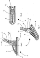
- the attachment element 38 comprises a body 39 provided above with a shank 13 intended for coupling with said handle.
- two through holes 14 and 15 are made that are intended for receiving the stem of a respective bolt for fixing the handle to the shank 13.
- a respective end 14a, 15a of said through holes is shaped so as to receive the nut of the bolt; the shaped ends 14a, 15a are made on opposite sides of the shank 13 to enable the handle to be mounted in a preset angular position in relation to the shank 13, as mentioned before.
- a seat 41 intended for receiving a damping element 42 ( Figures 23 to 25 ) the function of which will be explained in detail below.
- a damping element 42 Figures 23 to 25
- respective further through holes 41b are made that are aligned together and with the through holes 40 to enable the pivot 22 to pass through.
- the damping element 42 which comprises a body 43 in the top part of which, terminating above with a curved face 43a, there are obtained, on respective opposite faces 46, respective first seats 44 and second seats 45, intended for housing a respective torsion spring 50 ( Figure 26 ).
- respective through holes 47 are obtained that are aligned with one another, through which the locking element 24 is intended to pass when the damping element 42 is inserted into the seat 41 of the attachment element 38.
- the further through hole 48 is used for the passage of the pivot 22 when the damping element 42 is inserted into the seat 41 of the attachment element 38.
- a seat 49 is made that is intended for receiving the positioning element 28 disclosed above.
- the attachment element 38 When, during use of the tool according to the invention the supporting element 1 of the bristles 3 knocks against an obstacle, the attachment element 38, to which the handle of the tool is connected, can rotate by a few degrees around the pivot 22, in relation to the attachment element 38, the rotation being contrasted elastically by the torsion springs 50, which are mounted in the respective seats 44, 45 and elastically absorb the stress due to the impact of the supporting element 1 against an obstacle, so that said stress is not transmitted unchanged to the handle.
- the torsion springs are mounted so as to act in opposite directions, so as to enable rotation of the attachment element 38 to be contrasted elastically both in a clockwise and anticlockwise direction.
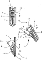
- FIGS 32 and 33 there is shown a third embodiment of an attachment element 51 according to the invention that is associable with the coupling element 8.
- the attachment element 51 comprises a body 52 provided with a shank 13 intended for coupling with a handle of the tool according to the invention.
- two through transverse holes 14 and 15 are made to receive the stem of a respective bolt for coupling and fixing said handle to the shank 13.
- a respective end 14a, 15a of said through holes is shaped so as to receive the nut of the bolt; the shaped ends 14a, 15a are made on opposite sides of the shank 13, to enable the handle to be mounted in a predefined angular position in relation to the shank 13, as mentioned before.
- a through hole 26 intended for receiving the pivot 22 that constitutes the rotation axis of the attachment element 51 in relation to the cradle 17 of the coupling element 8.
- respective through holes 54 are made that are aligned with one another and with the slits 23 of the coupling element 8 and are intended for receiving a further pivot 55 that protrudes from both ends from the through holes 54, to engage in the slits 23, so as to act as a stroke-stop element for the rotation of the attachment element 51 in relation to the coupling element 8.
- the attachment element 52 is not lockable in a fixed angular position in relation to the coupling element 8, but can rotate freely in relation thereto around the pivot 22, the rotation being elastically contrasted by the torsion springs 50 and limited by the interaction between the slits 23 and the further pivot 55: in fact, when through the effect of the rotation of the attachment element 51 the further pivot 55 knocks against the end edges of the slits 23, the rotation of the attachment element 51 stops.
- the size of the rotation of the attachment element 51 obviously depends on the length of the slits.
- This embodiment of the attachment element 52 is advantageously usable when it is foreseeable that the tool according to the invention has to be used in conditions that require frequent handle tilt variations to reach all the zones of the surface to be cleaned.
- torsion springs 50 are replaced by a leaf spring 56, associated with a damping element 42a.
- the leaf spring 56 is inserted between the upper curved surface 43a of the damping element 42a and the bottom of the seat 41 of the attachment element 38.
- the leaf spring 56 has on both sides two notches 56a, that divide each side of the spring into a central part 56b and two side parts 56c, that diverge in relation to the central part 56b.
- the side parts 56c interact with the body of the attachment element 38a to damp possible stress transmitted to the handle of the tool according to the invention by blows of the supporting element 1 against obstacles, performing the same function as the torsion springs 50 disclosed with reference to the previously disclosed attachment element 38.
- the central parts 56b of each side of the spring interact with respective protuberances 56d provided on opposite walls 46 of the damping element 42a to maintain the latter in position.
- the leaf spring 56 in relation to the torsion springs 50, has the advantage of having greater resistance to stress and greater ease of assembly.
- the coupling element 57 comprises a body 58 consisting of two walls 59 parallel to one another, partially connected by a connecting element 60, so that a space 61 between the two walls 59 remains accessible above from the outside.
- each wall 59 is connected to a horizontal fixing plate 62, provided with a series of holes 63 through which the fixing elements 73 ( Figure 42 ) can pass to connect the coupling element 57 to the supporting plate 1 of the bristles.
- Said fixing elements 73 may, for example, be self-tapping screws.
- each of the walls 59 there is made a slot 64 substantially with a circumference configuration, a plurality of further holes 65, arranged on a circumference arc internally concentric with respect to the slot 64 and a still further hole 66 the centre of which coincides substantially with the centre of the circumferences along which are arranged the slot 64 and the further holes 65.
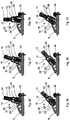
- the coupling element 57 is associable with a fourth embodiment of an attachment element 67, not forming part of the present invention, which is shown in Figures 39 to 47 .
- the attachment element 67 comprises a body 68 provided above with a shank 13 intended to be inserted into a hollow end of the handle of the tool according to the invention.
- the shank 13 is provided with two through holes 14 and 15 intended for receiving the stem of a respective bolt for coupling and fixing said handle to the shank 13.
- a respective end 14a, 15a of said through holes is shaped so as to receive the nut of the bolt; the shaped ends 14a, 15a are made on opposite sides of the shank 13, to enable a mounting of the handle in a preset angular position in relation to the shank 13, as mentioned before.
- the lower part 69 of the body 68 has a shape and dimensions such as to be inserted with minimum clearance into the space 61 between the walls 59 of the coupling element 57.
- a through hole 70 that, when the attachment element 67 is inserted into the space 61 between the walls 59 of the coupling element 57, is intended to be aligned with the holes 66 of said walls 59 to receive a pivot 70a ( Figure 44 ) constituting a rotation axis of the attachment element 67 in relation to the coupling element 57.
- the hole 70 can be made of dimensions such as to receive a bush that is free to rotate in the hole 70, that protrudes slightly from the ends of said hole 70 and through which the pivot 70a is passed. The bush is used to prevent possible friction between the attachment element 67 and the walls 59 of the coupling element 57, which would hinder the rotation of the attachment element 67 around the pivot 70a.
- a slot 71 is further made, having a circumference arc configuration intended to be aligned with the holes 65 made in the walls 59 of the coupling element 57, when the attachment element 67 is inserted into the space 61 between the walls 59 of said coupling element 57.
- Said holes 65 and said slot 71 are used to define the angular excursion of the attachment element 67 in relation to the coupling element 57.
- a plug 72 By inserting a plug 72 into a pair of corresponding holes 65 of the walls 59 the latter acts as a stroke stop for the angular excursion of the attachment element 67 in relation to the coupling element 57.
- the plug 72 passes through the slot 71 and when, through the effect of rotation of the attachment element 67 it comes into contact with an end wall of the slot 71, it prevents further rotation of the attachment element 67 in the direction of said end wall.
- the body 68 has a protrusion 74 on which is fixed an end of an elastic element 75, for example a coil spring, the opposite end of which is fixed to a fixing element 76 provided on the connecting element 60.
- an elastic element 75 for example a coil spring
- the elastic element 75 is used to absorb and dampen stress due to blows of the supporting element 1 against possible obstacles during use of the tool according to the invention.
- the angular position of the attachment element 67 in relation to the coupling element 57 can be fixed by a locking element 77, for example consisting of a bolt, the stem of which passes through the slots 64 of the walls 59 of the coupling element 57 and through a through hole 78 made in the body 68 of the attachment element 67.
- a further elastic element 81 for example a coil spring, for adjusting the clamping force exerted by the locking element 77.
- This clamping force determines the friction resistance that develops between the walls 59 of the coupling element 57 and the body 68 of the attachment element 67 and which contrasts the rotation of the attachment element 67 in relation to the coupling element 57, so as to enable or prevent rotation movements of the attachment element 67 according to whether, during use of the tool according to the invention, a variation of the angle of the element 67 in relation to the element 57 is necessary or not.
- FIG 48 there is illustrated a version of the coupling between the attachment element 67 and the coupling element 57, not forming part of the present invention, in which there is no elastic element 75.
- the damping of stress due to possible blows of the tool against an obstacle is entrusted to the friction resistance between the walls 59 of the coupling element 57 and the body 68 of the attachment element 67, which is adjustable by tightening the bolt 77 and the further spring 81 inserted onto the shaft of the bolt 77.
- FIG. 49 to 51 there is illustrated a fifth embodiment of an attachment element 82, not forming part of the present invention, associable with the coupling element 57.
- the attachment element 82 comprises a body 83 provided above with a shank 13 intended to be inserted into a hollow end of the handle of the tool according to the invention.
- the shank 13 is provided with two through holes 14 and 15 intended for receiving the stem of a respective bolt for coupling and fixing said handle to the shank 13.
- a respective end 14a, 15a of said through holes is shaped so as to receive the nut of the bolt; the shaped ends 14a, 15a are made on opposite sides of the shank 13, to enable a mounting of the handle in a preset angular position in relation to the shank 13, as mentioned before.
- the lower part 84 of the body 83 has a shape and dimensions such as to be inserted with minimum clearance into the space 61 between the walls 59 of the coupling element 57.
- a through hole 84a is made that, when the attachment element 82 is inserted into the space 61 between the walls 59 of the coupling element 57, is intended to align itself on the holes 66 of said walls 59 to receive the pivot 70a constituting the rotation axis of the attachment element 82 in relation to the coupling element 57.
- Said pivot 70a can be housed inside a bush, as already disclosed above.
- a seat 85 is further obtained that is intended for housing an elastic element 86 ( Figures 52 and 53 ), for example a coil spring.
- the seat 85 communicates at an end with a slot 87 into which a bush 88 is inserted into which the spindle of the locking element 77 disclosed above passes.
- the slot 87 has a shape and dimensions such as to permit small rotations of the attachment element 82 in relation to the coupling element 57 when the locking element is in the clamping position.
- the attachment element 82 has the advantage that the springing force provided by the spring 85 is constant in any corresponding angular position of the attachment element in relation to the coupling element.
- the slot 87 and the bush 88 can be dimensioned so that the bush 88 can receive the coil spring 81, to adjust the clamping force exerted by the locking element 77.
- the coil spring 81 is thus not visible on the outside of the coupling element, making the aesthetics thereof more appealing.
- FIG 54 there is shown a fourth embodiment of a coupling element 89 not forming part of the present invention.
- the coupling element 89 is suitable for coupling with the attachment elements 67, or 82.
- the coupling element 89 is provided with a base 90 suitable for being slidingly inserted into the seat 3 of the supporting element 1.
- the base 90 is provided peripherally with a groove 91, intended for coupling with the protrusions 4 of the supporting element 1, so that movements of the coupling element 89 are prevented in a direction perpendicular to the seat 3 of the supporting element 1.
- the coupling element 89 further comprises two walls 92 that are parallel to one another that rise from the base 90 and are substantially perpendicular thereto; the two walls 92 define a space 93 together into which the lower part 69, respectively 84, of an attachment element 67, respectively 82, is inserted.
- each of the walls 92 there is made a slot 94, with a substantially circumference arc configuration, intended for the passage of the stem of the bolt 80, to enable or prevent a possible variation of the angular position of the attachment element.
- the slot 94 is surrounded by respective seats 99 and 100 made respectively on the external side and on the internal side of the respective wall 94, said seats 99, 100 being suitable for housing respective wearproof elements (not shown) the object of which is to prevent progressive wear to the walls 94 through the effect of the friction that develops between the walls 94 and the attachment element when the locking element is clamped.
- Each wall 92 is further provided with a hole 95 that is intended to align itself with the hole 70, respectively 84a, of the attachment element 67, respectively 82, for receiving the pivot 70a constituting the rotation axis of the attachment element 67, respectively 82, in relation to the coupling element 89.
- FIGS 55 and 56 there is illustrated an adapting element 96, not forming part of the present invention, that is insertible in a shapingly coupled manner onto the shank 13 of an attachment element and is intended to be inserted into the hollow end of the handle of the tool.
- an adapting element 96 By varying the external diameter of the adapting element 96 it is possible to couple handles of various diameter with the attachment element.
- the adapting element 96 is provided with holes 97 for passing fixing elements of the handle to the shank 13.
- the shaping coupling between the adapting element 96 and the shank 13 is made in such a manner that when the handle of the attachment element is extracted the adaptor remains fixed to the shank 13.
- FIG 57 there is illustrated a sixth embodiment of an attachment element 101, not forming part of the present invention, associable with the coupling element 57, or 89.
- the attachment element 101 comprises a body 102 provided above with a shank 13 intended to be inserted into a hollow end of the handle of the tool according to the invention.
- the shank 13 is provided with two through holes 14 and 15 intended for receiving the stem of a respective bolt for coupling and fixing said handle to the shank 13.
- a respective end 14a, 15a of said through holes is shaped so as to receive the nut of the bolt; the shaped ends 14a, 15a are made on opposite sides of the shank 13, to enable a mounting of the handle in a preset angular position in relation to the shank 13, as mentioned before.
- the lower part 104 of the body 102 has a shape and dimensions such as to be inserted with minimum clearance into the space 61 between the walls 59 of the coupling element 57, and the space 93 between the walls 92 of the coupling element 89.
- a through hole 105 that, when the attachment element 101 is inserted into the space 61 between the walls 59 of the coupling element 57, or into the space 93 between the walls 92 of the coupling element 89, is intended to be aligned with the holes 66 of said walls 59, or with the holes 95 of said walls 92, to receive the pivot 70a constituting the rotation axis of the attachment element 101 in relation to the coupling element 57, or 89.
- Said pivot 70a can be housed inside a bush, as already disclosed above.
- the further through hole 103 and said bush can be dimensioned so that the bush can receive the coil spring 81 to adjust the clamping force exerted by the locking element 77.
- the coil spring 81 will thus not be visible from the outside of the coupling element, making the aesthetics thereof more appealing.
- the handle 105 at the end thereof intended to be coupled with the shank 13 of the attachment element, is provided with a first hole 107, intended to be aligned with the end of the hole 14 of the shank 13 opposite the seat 14a, and with a second hole 108, intended to be aligned with the end of the hole 15 of the shank 13 opposite the seat 15a.
- the arrangement of the holes 107 and 108 is such that the handle 105 can be mounted on the shank 13 in a preset angular position, that position, i.e. in which the holes 107 and 108 are aligned with the holes 14 and 15 of the shank 13, as disclosed above.
- the handle 105 has an ergonomic shape that requires a preset mounting position, inasmuch as the arrangement of the holes 107 and 108 prevents the handle being mounted in a position that is not correct, i.e. in a position other than the preset position.
- the holes 97 of the adapting element will be aligned with the holes 107 and 108 of the handle 105 and with the holes 14 and 15 of the shank 13.
Landscapes
- Engineering & Computer Science (AREA)
- Mechanical Engineering (AREA)
- Cleaning Implements For Floors, Carpets, Furniture, Walls, And The Like (AREA)
- Brushes (AREA)
- Workshop Equipment, Work Benches, Supports, Or Storage Means (AREA)
Priority Applications (1)
| Application Number | Priority Date | Filing Date | Title |
|---|---|---|---|
| PL14198348T PL2875751T3 (pl) | 2007-06-22 | 2008-06-18 | Narzędzie do czyszczenia powierzchni |
Applications Claiming Priority (2)
| Application Number | Priority Date | Filing Date | Title |
|---|---|---|---|
| IT000215A ITMO20070215A1 (it) | 2007-06-22 | 2007-06-22 | Attrezzo per pulire superfici |
| EP08762908.5A EP2164361B1 (en) | 2007-06-22 | 2008-06-18 | Tool for cleaning surfaces |
Related Parent Applications (1)
| Application Number | Title | Priority Date | Filing Date |
|---|---|---|---|
| EP08762908.5A Division EP2164361B1 (en) | 2007-06-22 | 2008-06-18 | Tool for cleaning surfaces |
Publications (2)
| Publication Number | Publication Date |
|---|---|
| EP2875751A1 EP2875751A1 (en) | 2015-05-27 |
| EP2875751B1 true EP2875751B1 (en) | 2016-08-24 |
Family
ID=40125853
Family Applications (2)
| Application Number | Title | Priority Date | Filing Date |
|---|---|---|---|
| EP14198348.6A Active EP2875751B1 (en) | 2007-06-22 | 2008-06-18 | Tool for cleaning surfaces |
| EP08762908.5A Active EP2164361B1 (en) | 2007-06-22 | 2008-06-18 | Tool for cleaning surfaces |
Family Applications After (1)
| Application Number | Title | Priority Date | Filing Date |
|---|---|---|---|
| EP08762908.5A Active EP2164361B1 (en) | 2007-06-22 | 2008-06-18 | Tool for cleaning surfaces |
Country Status (10)
| Country | Link |
|---|---|
| US (1) | US9307825B2 (pl) |
| EP (2) | EP2875751B1 (pl) |
| CN (1) | CN101795598B (pl) |
| CA (1) | CA2691946C (pl) |
| DK (1) | DK2875751T3 (pl) |
| ES (2) | ES2603069T3 (pl) |
| IT (1) | ITMO20070215A1 (pl) |
| PL (2) | PL2875751T3 (pl) |
| RU (1) | RU2478328C2 (pl) |
| WO (1) | WO2009001186A2 (pl) |
Families Citing this family (5)
| Publication number | Priority date | Publication date | Assignee | Title |
|---|---|---|---|---|
| FR3034968B1 (fr) * | 2015-04-15 | 2019-06-14 | L'oreal | Mecanisme d'articulation d'un dispositif d'application de produit cosmetique, dispositif, methode d'application et procede de fabrication associes |
| KR101796645B1 (ko) * | 2015-09-04 | 2017-11-10 | 신일산업 주식회사 | 청소기의 핸들각도 조절장치 |
| KR101796646B1 (ko) * | 2015-09-04 | 2017-11-10 | 신일산업 주식회사 | 스팀 청소기 |
| ITUA20162136A1 (it) * | 2016-03-31 | 2017-10-01 | Nuova F Lli Dondi S R L | Attacco per attrezzi per pulizia |
| IT202300022956A1 (it) * | 2023-10-31 | 2025-05-01 | Nuova F Lli Dondi S R L | Attrezzo di pulitura di superfici |
Family Cites Families (30)
| Publication number | Priority date | Publication date | Assignee | Title |
|---|---|---|---|---|
| US881782A (en) * | 1907-04-24 | 1908-03-10 | George F Elliott | Intrenching-tool. |
| US974331A (en) * | 1909-10-04 | 1910-11-01 | John Aasen | Wrench. |
| US1755486A (en) * | 1929-07-22 | 1930-04-22 | Ross E Odell | Wrench |
| US2304745A (en) * | 1941-02-25 | 1942-12-08 | Apex Electrical Mfg Co | Handle and latch construction |
| US4819294A (en) * | 1987-03-06 | 1989-04-11 | Thomas Industries, Inc. | Pad-type applicator with adjusting handle |
| IT214851Z2 (it) | 1988-06-06 | 1990-06-18 | Diap Srl | Grazie ad una robusta spazzola spazzolone dotato di un boccaglio realizzata in resine termoplastiche per il manico regolabile in inclinazione, in grado di ripulire e livellare suoli di qualsiasi genere |
| DE3937718A1 (de) * | 1989-11-13 | 1991-05-16 | Henkel Kgaa | Mopbezug mit einer tasche und einer lasche |
| US5414889A (en) * | 1994-01-14 | 1995-05-16 | M. B. Walton, Inc. | Broom with position-maintaining multi-angle handle interconnector |
| DE4424428A1 (de) | 1994-07-12 | 1996-01-18 | Coronet Werke Gmbh | Vorrichtung zum lösbaren Befestigen von Reinigungsgeräten |
| US5615442A (en) | 1995-12-20 | 1997-04-01 | Vining Industries, Inc. | Mop including mop connector |
| ES1037421Y (es) * | 1997-05-30 | 1998-11-01 | Lekue S L | Dispositivo de limpieza. |
| CA2226465C (en) | 1998-01-07 | 2001-06-19 | David E. Herbut | Adjustable connector device for a curling broom |
| US6315341B1 (en) * | 2000-08-11 | 2001-11-13 | Sandra Leon | Shovel having an adjustable blade angle |
| TW505012U (en) * | 2000-12-27 | 2002-10-01 | Jung-Yuan Jiang | Improved structure of the cleaning brush |
| US20030009839A1 (en) * | 2001-06-25 | 2003-01-16 | Streutker Alen David | Cleaning implement and joint therefor |
| US20030180085A1 (en) * | 2002-03-19 | 2003-09-25 | Hughes David P. | All in one home and yard maintenance tool package and method therefor |
| JP4041706B2 (ja) * | 2002-07-22 | 2008-01-30 | ユニ・チャーム株式会社 | 清掃用保持具およびその清掃用保持具を用いた清掃物品 |
| WO2005044042A2 (en) | 2003-07-03 | 2005-05-19 | Freudenberg Household Products Lp | Broom, method, and broom display |
| US7032941B2 (en) * | 2003-08-06 | 2006-04-25 | Heneveld William R | Tool including adjustable handle |
| US20060191088A1 (en) * | 2003-08-15 | 2006-08-31 | Goulet Matthew G | Paint application device |
| JP4365231B2 (ja) | 2003-09-09 | 2009-11-18 | アズマ工業株式会社 | 柄付き清掃具 |
| US7491005B2 (en) * | 2004-05-27 | 2009-02-17 | Aquastar, Inc; Aquastar Usa | Mop/cleaner handle |
| US20060037159A1 (en) * | 2004-08-18 | 2006-02-23 | Meiko Pet Corporation. | Aquarium cleaning mop |
| US20060117511A1 (en) | 2004-12-02 | 2006-06-08 | Weaver Jace A | Pushbroom with support brace |
| US7891898B2 (en) * | 2005-01-28 | 2011-02-22 | S.C. Johnson & Son, Inc. | Cleaning pad for wet, damp or dry cleaning |
| ATE390865T1 (de) | 2005-11-04 | 2008-04-15 | Rayen Sl | Verstellbarer besen |
| CN2877416Y (zh) * | 2006-04-04 | 2007-03-14 | 陆建新 | 刷柄角度可调式平板刷 |
| US7401538B2 (en) * | 2006-06-12 | 2008-07-22 | Chin-Shun Cheng | F figure wrench |
| US7735182B2 (en) * | 2006-07-18 | 2010-06-15 | Kimberly-Clark Worldwide, Inc. | Mop assembly with reversible head |
| US7509893B2 (en) * | 2007-06-27 | 2009-03-31 | Proxene Tools Co., Ltd. | Locking device for locking pivotable head of hand tool |
-
2007
- 2007-06-22 IT IT000215A patent/ITMO20070215A1/it unknown
-
2008
- 2008-06-18 ES ES14198348.6T patent/ES2603069T3/es active Active
- 2008-06-18 CA CA2691946A patent/CA2691946C/en not_active Expired - Fee Related
- 2008-06-18 EP EP14198348.6A patent/EP2875751B1/en active Active
- 2008-06-18 US US12/666,092 patent/US9307825B2/en active Active
- 2008-06-18 ES ES08762908.5T patent/ES2532379T3/es active Active
- 2008-06-18 WO PCT/IB2008/001582 patent/WO2009001186A2/en not_active Ceased
- 2008-06-18 PL PL14198348T patent/PL2875751T3/pl unknown
- 2008-06-18 DK DK14198348.6T patent/DK2875751T3/en active
- 2008-06-18 CN CN2008801008662A patent/CN101795598B/zh not_active Expired - Fee Related
- 2008-06-18 RU RU2010101928/12A patent/RU2478328C2/ru active
- 2008-06-18 EP EP08762908.5A patent/EP2164361B1/en active Active
- 2008-06-18 PL PL08762908T patent/PL2164361T3/pl unknown
Also Published As
| Publication number | Publication date |
|---|---|
| WO2009001186A3 (en) | 2009-02-26 |
| EP2164361A2 (en) | 2010-03-24 |
| CN101795598A (zh) | 2010-08-04 |
| EP2875751A1 (en) | 2015-05-27 |
| EP2164361B1 (en) | 2014-12-17 |
| CA2691946A1 (en) | 2008-12-31 |
| ITMO20070215A1 (it) | 2008-12-23 |
| RU2478328C2 (ru) | 2013-04-10 |
| RU2010101928A (ru) | 2011-07-27 |
| CN101795598B (zh) | 2012-03-28 |
| ES2603069T3 (es) | 2017-02-23 |
| CA2691946C (en) | 2015-11-10 |
| US9307825B2 (en) | 2016-04-12 |
| PL2164361T3 (pl) | 2015-05-29 |
| PL2875751T3 (pl) | 2017-04-28 |
| ES2532379T3 (es) | 2015-03-26 |
| WO2009001186A2 (en) | 2008-12-31 |
| DK2875751T3 (en) | 2016-12-12 |
| US20100205759A1 (en) | 2010-08-19 |
Similar Documents
| Publication | Publication Date | Title |
|---|---|---|
| EP2164361B1 (en) | Tool for cleaning surfaces | |
| US8708059B2 (en) | Mounting assembly for handle for power tool | |
| US8234756B2 (en) | Handle for power tool | |
| CA2678666C (en) | Offset taping knife | |
| US20060123575A1 (en) | Adjustable holder for cleaning implement | |
| CN104755365A (zh) | 有弹性的自行车把手 | |
| CA2912331A1 (en) | Handle for cleaning tool or similar | |
| CN102483083A (zh) | 用于工具和手柄的连接组件 | |
| WO2007029016A1 (en) | Tool handles | |
| CA2359806A1 (en) | Paintbrush with adjustable head | |
| US9517548B2 (en) | Device and method for holding a tool bit | |
| JP6341453B2 (ja) | エレベータの敷居清掃装置および取付治具 | |
| KR20220013684A (ko) | 휴대용 마사지기 | |
| US20220364375A1 (en) | Tool for the mechanical treatment of a concrete floor | |
| US2804637A (en) | Sweeping brush with frictionally adjustable handle | |
| KR200205512Y1 (ko) | 길이와 각도조절이 가능한 빗자루 | |
| WO2007010357A2 (en) | Working tool | |
| KR101547433B1 (ko) | 계단용 논슬립 전동 청소장치 | |
| WO2004060131A1 (en) | Roller-type mop | |
| EP1782712B1 (en) | Adjustable broom | |
| CN223196019U (zh) | 角度可调的手持式洗地机 | |
| KR200357999Y1 (ko) | 거울이 부착된 브러쉬 | |
| KR200446040Y1 (ko) | 블라인드 클리너 | |
| KR200173304Y1 (ko) | 길이조절이 가능한 봉 | |
| KR20260067168A (ko) | 밀대걸레용 보조조립부재 |
Legal Events
| Date | Code | Title | Description |
|---|---|---|---|
| PUAI | Public reference made under article 153(3) epc to a published international application that has entered the european phase |
Free format text: ORIGINAL CODE: 0009012 |
|
| 17P | Request for examination filed |
Effective date: 20141216 |
|
| AC | Divisional application: reference to earlier application |
Ref document number: 2164361 Country of ref document: EP Kind code of ref document: P |
|
| AK | Designated contracting states |
Kind code of ref document: A1 Designated state(s): AT BE BG CH CY CZ DE DK EE ES FI FR GB GR HR HU IE IS IT LI LT LU LV MC MT NL NO PL PT RO SE SI SK TR |
|
| R17P | Request for examination filed (corrected) |
Effective date: 20151127 |
|
| RBV | Designated contracting states (corrected) |
Designated state(s): AT BE BG CH CY CZ DE DK EE ES FI FR GB GR HR HU IE IS IT LI LT LU LV MC MT NL NO PL PT RO SE SI SK TR |
|
| GRAP | Despatch of communication of intention to grant a patent |
Free format text: ORIGINAL CODE: EPIDOSNIGR1 |
|
| RIC1 | Information provided on ipc code assigned before grant |
Ipc: A46B 5/00 20060101AFI20160210BHEP Ipc: A46B 7/04 20060101ALI20160210BHEP |
|
| INTG | Intention to grant announced |
Effective date: 20160309 |
|
| GRAS | Grant fee paid |
Free format text: ORIGINAL CODE: EPIDOSNIGR3 |
|
| GRAA | (expected) grant |
Free format text: ORIGINAL CODE: 0009210 |
|
| RIN1 | Information on inventor provided before grant (corrected) |
Inventor name: DONDI, ANDREA Inventor name: DONDI, ROBERTO |
|
| AC | Divisional application: reference to earlier application |
Ref document number: 2164361 Country of ref document: EP Kind code of ref document: P |
|
| AK | Designated contracting states |
Kind code of ref document: B1 Designated state(s): AT BE BG CH CY CZ DE DK EE ES FI FR GB GR HR HU IE IS IT LI LT LU LV MC MT NL NO PL PT RO SE SI SK TR |
|
| REG | Reference to a national code |
Ref country code: GB Ref legal event code: FG4D |
|
| REG | Reference to a national code |
Ref country code: CH Ref legal event code: EP |
|
| REG | Reference to a national code |
Ref country code: AT Ref legal event code: REF Ref document number: 822242 Country of ref document: AT Kind code of ref document: T Effective date: 20160915 |
|
| REG | Reference to a national code |
Ref country code: IE Ref legal event code: FG4D |
|
| REG | Reference to a national code |
Ref country code: DE Ref legal event code: R096 Ref document number: 602008045947 Country of ref document: DE |
|
| REG | Reference to a national code |
Ref country code: CH Ref legal event code: NV Representative=s name: FIAMMENGHI-FIAMMENGHI, CH |
|
| REG | Reference to a national code |
Ref country code: RO Ref legal event code: EPE |
|
| REG | Reference to a national code |
Ref country code: NL Ref legal event code: FP |
|
| REG | Reference to a national code |
Ref country code: DK Ref legal event code: T3 Effective date: 20161207 |
|
| REG | Reference to a national code |
Ref country code: LT Ref legal event code: MG4D |
|
| REG | Reference to a national code |
Ref country code: AT Ref legal event code: MK05 Ref document number: 822242 Country of ref document: AT Kind code of ref document: T Effective date: 20160824 |
|
| PG25 | Lapsed in a contracting state [announced via postgrant information from national office to epo] |
Ref country code: HR Free format text: LAPSE BECAUSE OF FAILURE TO SUBMIT A TRANSLATION OF THE DESCRIPTION OR TO PAY THE FEE WITHIN THE PRESCRIBED TIME-LIMIT Effective date: 20160824 Ref country code: FI Free format text: LAPSE BECAUSE OF FAILURE TO SUBMIT A TRANSLATION OF THE DESCRIPTION OR TO PAY THE FEE WITHIN THE PRESCRIBED TIME-LIMIT Effective date: 20160824 Ref country code: LT Free format text: LAPSE BECAUSE OF FAILURE TO SUBMIT A TRANSLATION OF THE DESCRIPTION OR TO PAY THE FEE WITHIN THE PRESCRIBED TIME-LIMIT Effective date: 20160824 Ref country code: NO Free format text: LAPSE BECAUSE OF FAILURE TO SUBMIT A TRANSLATION OF THE DESCRIPTION OR TO PAY THE FEE WITHIN THE PRESCRIBED TIME-LIMIT Effective date: 20161124 |
|
| REG | Reference to a national code |
Ref country code: ES Ref legal event code: FG2A Ref document number: 2603069 Country of ref document: ES Kind code of ref document: T3 Effective date: 20170223 |
|
| PG25 | Lapsed in a contracting state [announced via postgrant information from national office to epo] |
Ref country code: GR Free format text: LAPSE BECAUSE OF FAILURE TO SUBMIT A TRANSLATION OF THE DESCRIPTION OR TO PAY THE FEE WITHIN THE PRESCRIBED TIME-LIMIT Effective date: 20161125 Ref country code: SE Free format text: LAPSE BECAUSE OF FAILURE TO SUBMIT A TRANSLATION OF THE DESCRIPTION OR TO PAY THE FEE WITHIN THE PRESCRIBED TIME-LIMIT Effective date: 20160824 Ref country code: LV Free format text: LAPSE BECAUSE OF FAILURE TO SUBMIT A TRANSLATION OF THE DESCRIPTION OR TO PAY THE FEE WITHIN THE PRESCRIBED TIME-LIMIT Effective date: 20160824 Ref country code: PT Free format text: LAPSE BECAUSE OF FAILURE TO SUBMIT A TRANSLATION OF THE DESCRIPTION OR TO PAY THE FEE WITHIN THE PRESCRIBED TIME-LIMIT Effective date: 20161226 Ref country code: AT Free format text: LAPSE BECAUSE OF FAILURE TO SUBMIT A TRANSLATION OF THE DESCRIPTION OR TO PAY THE FEE WITHIN THE PRESCRIBED TIME-LIMIT Effective date: 20160824 |
|
| PG25 | Lapsed in a contracting state [announced via postgrant information from national office to epo] |
Ref country code: EE Free format text: LAPSE BECAUSE OF FAILURE TO SUBMIT A TRANSLATION OF THE DESCRIPTION OR TO PAY THE FEE WITHIN THE PRESCRIBED TIME-LIMIT Effective date: 20160824 |
|
| REG | Reference to a national code |
Ref country code: FR Ref legal event code: PLFP Year of fee payment: 10 |
|
| REG | Reference to a national code |
Ref country code: DE Ref legal event code: R097 Ref document number: 602008045947 Country of ref document: DE |
|
| PG25 | Lapsed in a contracting state [announced via postgrant information from national office to epo] |
Ref country code: SK Free format text: LAPSE BECAUSE OF FAILURE TO SUBMIT A TRANSLATION OF THE DESCRIPTION OR TO PAY THE FEE WITHIN THE PRESCRIBED TIME-LIMIT Effective date: 20160824 Ref country code: BE Free format text: LAPSE BECAUSE OF FAILURE TO SUBMIT A TRANSLATION OF THE DESCRIPTION OR TO PAY THE FEE WITHIN THE PRESCRIBED TIME-LIMIT Effective date: 20160824 Ref country code: BG Free format text: LAPSE BECAUSE OF FAILURE TO SUBMIT A TRANSLATION OF THE DESCRIPTION OR TO PAY THE FEE WITHIN THE PRESCRIBED TIME-LIMIT Effective date: 20161124 |
|
| PLBE | No opposition filed within time limit |
Free format text: ORIGINAL CODE: 0009261 |
|
| STAA | Information on the status of an ep patent application or granted ep patent |
Free format text: STATUS: NO OPPOSITION FILED WITHIN TIME LIMIT |
|
| 26N | No opposition filed |
Effective date: 20170526 |
|
| PG25 | Lapsed in a contracting state [announced via postgrant information from national office to epo] |
Ref country code: SI Free format text: LAPSE BECAUSE OF FAILURE TO SUBMIT A TRANSLATION OF THE DESCRIPTION OR TO PAY THE FEE WITHIN THE PRESCRIBED TIME-LIMIT Effective date: 20160824 |
|
| PG25 | Lapsed in a contracting state [announced via postgrant information from national office to epo] |
Ref country code: MC Free format text: LAPSE BECAUSE OF FAILURE TO SUBMIT A TRANSLATION OF THE DESCRIPTION OR TO PAY THE FEE WITHIN THE PRESCRIBED TIME-LIMIT Effective date: 20160824 |
|
| REG | Reference to a national code |
Ref country code: IE Ref legal event code: MM4A |
|
| PG25 | Lapsed in a contracting state [announced via postgrant information from national office to epo] |
Ref country code: LU Free format text: LAPSE BECAUSE OF NON-PAYMENT OF DUE FEES Effective date: 20170618 Ref country code: IE Free format text: LAPSE BECAUSE OF NON-PAYMENT OF DUE FEES Effective date: 20170618 |
|
| REG | Reference to a national code |
Ref country code: FR Ref legal event code: PLFP Year of fee payment: 11 |
|
| PGFP | Annual fee paid to national office [announced via postgrant information from national office to epo] |
Ref country code: NL Payment date: 20180626 Year of fee payment: 11 |
|
| PGFP | Annual fee paid to national office [announced via postgrant information from national office to epo] |
Ref country code: RO Payment date: 20180608 Year of fee payment: 11 |
|
| PG25 | Lapsed in a contracting state [announced via postgrant information from national office to epo] |
Ref country code: MT Free format text: LAPSE BECAUSE OF NON-PAYMENT OF DUE FEES Effective date: 20170618 |
|
| PGFP | Annual fee paid to national office [announced via postgrant information from national office to epo] |
Ref country code: CH Payment date: 20180704 Year of fee payment: 11 Ref country code: DK Payment date: 20180625 Year of fee payment: 11 |
|
| PG25 | Lapsed in a contracting state [announced via postgrant information from national office to epo] |
Ref country code: HU Free format text: LAPSE BECAUSE OF FAILURE TO SUBMIT A TRANSLATION OF THE DESCRIPTION OR TO PAY THE FEE WITHIN THE PRESCRIBED TIME-LIMIT; INVALID AB INITIO Effective date: 20080618 |
|
| PG25 | Lapsed in a contracting state [announced via postgrant information from national office to epo] |
Ref country code: CY Free format text: LAPSE BECAUSE OF FAILURE TO SUBMIT A TRANSLATION OF THE DESCRIPTION OR TO PAY THE FEE WITHIN THE PRESCRIBED TIME-LIMIT Effective date: 20160824 |
|
| REG | Reference to a national code |
Ref country code: DK Ref legal event code: EBP Effective date: 20190630 |
|
| PG25 | Lapsed in a contracting state [announced via postgrant information from national office to epo] |
Ref country code: RO Free format text: LAPSE BECAUSE OF NON-PAYMENT OF DUE FEES Effective date: 20190618 |
|
| REG | Reference to a national code |
Ref country code: CH Ref legal event code: PL |
|
| REG | Reference to a national code |
Ref country code: NL Ref legal event code: MM Effective date: 20190701 |
|
| PG25 | Lapsed in a contracting state [announced via postgrant information from national office to epo] |
Ref country code: NL Free format text: LAPSE BECAUSE OF NON-PAYMENT OF DUE FEES Effective date: 20190701 |
|
| PG25 | Lapsed in a contracting state [announced via postgrant information from national office to epo] |
Ref country code: CH Free format text: LAPSE BECAUSE OF NON-PAYMENT OF DUE FEES Effective date: 20190630 Ref country code: LI Free format text: LAPSE BECAUSE OF NON-PAYMENT OF DUE FEES Effective date: 20190630 |
|
| PG25 | Lapsed in a contracting state [announced via postgrant information from national office to epo] |
Ref country code: DK Free format text: LAPSE BECAUSE OF NON-PAYMENT OF DUE FEES Effective date: 20190630 Ref country code: IS Free format text: LAPSE BECAUSE OF FAILURE TO SUBMIT A TRANSLATION OF THE DESCRIPTION OR TO PAY THE FEE WITHIN THE PRESCRIBED TIME-LIMIT Effective date: 20161224 |
|
| PGFP | Annual fee paid to national office [announced via postgrant information from national office to epo] |
Ref country code: CZ Payment date: 20210608 Year of fee payment: 14 |
|
| PGFP | Annual fee paid to national office [announced via postgrant information from national office to epo] |
Ref country code: TR Payment date: 20210608 Year of fee payment: 14 Ref country code: GB Payment date: 20210628 Year of fee payment: 14 |
|
| PGFP | Annual fee paid to national office [announced via postgrant information from national office to epo] |
Ref country code: DE Payment date: 20220629 Year of fee payment: 15 |
|
| PG25 | Lapsed in a contracting state [announced via postgrant information from national office to epo] |
Ref country code: CZ Free format text: LAPSE BECAUSE OF NON-PAYMENT OF DUE FEES Effective date: 20220618 |
|
| GBPC | Gb: european patent ceased through non-payment of renewal fee |
Effective date: 20220618 |
|
| PG25 | Lapsed in a contracting state [announced via postgrant information from national office to epo] |
Ref country code: GB Free format text: LAPSE BECAUSE OF NON-PAYMENT OF DUE FEES Effective date: 20220618 |
|
| PGFP | Annual fee paid to national office [announced via postgrant information from national office to epo] |
Ref country code: FR Payment date: 20230626 Year of fee payment: 16 |
|
| PGFP | Annual fee paid to national office [announced via postgrant information from national office to epo] |
Ref country code: PL Payment date: 20230602 Year of fee payment: 16 |
|
| PGFP | Annual fee paid to national office [announced via postgrant information from national office to epo] |
Ref country code: ES Payment date: 20230703 Year of fee payment: 16 |
|
| REG | Reference to a national code |
Ref country code: DE Ref legal event code: R119 Ref document number: 602008045947 Country of ref document: DE |
|
| PG25 | Lapsed in a contracting state [announced via postgrant information from national office to epo] |
Ref country code: DE Free format text: LAPSE BECAUSE OF NON-PAYMENT OF DUE FEES Effective date: 20240103 |
|
| PG25 | Lapsed in a contracting state [announced via postgrant information from national office to epo] |
Ref country code: TR Free format text: LAPSE BECAUSE OF NON-PAYMENT OF DUE FEES Effective date: 20220618 |
|
| PG25 | Lapsed in a contracting state [announced via postgrant information from national office to epo] |
Ref country code: FR Free format text: LAPSE BECAUSE OF NON-PAYMENT OF DUE FEES Effective date: 20240630 |
|
| REG | Reference to a national code |
Ref country code: ES Ref legal event code: FD2A Effective date: 20250801 |
|
| PG25 | Lapsed in a contracting state [announced via postgrant information from national office to epo] |
Ref country code: ES Free format text: LAPSE BECAUSE OF NON-PAYMENT OF DUE FEES Effective date: 20240619 |
|
| PG25 | Lapsed in a contracting state [announced via postgrant information from national office to epo] |
Ref country code: PL Free format text: LAPSE BECAUSE OF NON-PAYMENT OF DUE FEES Effective date: 20240618 |
|
| PGFP | Annual fee paid to national office [announced via postgrant information from national office to epo] |
Ref country code: IT Payment date: 20250625 Year of fee payment: 18 |