EP2874032B1 - Target signature closed loop control system and method - Google Patents
Target signature closed loop control system and method Download PDFInfo
- Publication number
- EP2874032B1 EP2874032B1 EP14191361.6A EP14191361A EP2874032B1 EP 2874032 B1 EP2874032 B1 EP 2874032B1 EP 14191361 A EP14191361 A EP 14191361A EP 2874032 B1 EP2874032 B1 EP 2874032B1
- Authority
- EP
- European Patent Office
- Prior art keywords
- signature
- section
- machine
- cavities
- event timing
- Prior art date
- Legal status (The legal status is an assumption and is not a legal conclusion. Google has not performed a legal analysis and makes no representation as to the accuracy of the status listed.)
- Active
Links
- 238000000034 method Methods 0.000 title claims description 73
- 230000008569 process Effects 0.000 claims description 50
- 239000011521 glass Substances 0.000 claims description 36
- 238000005259 measurement Methods 0.000 claims description 26
- 238000000605 extraction Methods 0.000 claims description 14
- 238000012544 monitoring process Methods 0.000 claims description 8
- 230000004044 response Effects 0.000 claims description 8
- 238000010238 partial least squares regression Methods 0.000 claims description 6
- 230000008859 change Effects 0.000 claims description 4
- 230000005855 radiation Effects 0.000 claims description 4
- 238000012935 Averaging Methods 0.000 claims description 3
- 230000003467 diminishing effect Effects 0.000 claims description 3
- 238000004458 analytical method Methods 0.000 claims description 2
- 238000003384 imaging method Methods 0.000 claims description 2
- 230000001131 transforming effect Effects 0.000 claims 1
- 239000013598 vector Substances 0.000 description 39
- 239000011159 matrix material Substances 0.000 description 19
- 238000013459 approach Methods 0.000 description 8
- 238000007496 glass forming Methods 0.000 description 7
- 238000000513 principal component analysis Methods 0.000 description 6
- 230000000875 corresponding effect Effects 0.000 description 5
- 230000033001 locomotion Effects 0.000 description 5
- 230000002596 correlated effect Effects 0.000 description 4
- 238000009826 distribution Methods 0.000 description 4
- 238000004519 manufacturing process Methods 0.000 description 4
- 230000004048 modification Effects 0.000 description 4
- 238000012986 modification Methods 0.000 description 4
- 230000009286 beneficial effect Effects 0.000 description 3
- 230000001276 controlling effect Effects 0.000 description 3
- 230000004075 alteration Effects 0.000 description 2
- 230000008901 benefit Effects 0.000 description 2
- 238000006243 chemical reaction Methods 0.000 description 2
- 238000000354 decomposition reaction Methods 0.000 description 2
- 230000003292 diminished effect Effects 0.000 description 2
- 238000007689 inspection Methods 0.000 description 2
- 230000009467 reduction Effects 0.000 description 2
- 238000004088 simulation Methods 0.000 description 2
- 230000009466 transformation Effects 0.000 description 2
- 230000003321 amplification Effects 0.000 description 1
- 230000015572 biosynthetic process Effects 0.000 description 1
- 230000008878 coupling Effects 0.000 description 1
- 238000010168 coupling process Methods 0.000 description 1
- 238000005859 coupling reaction Methods 0.000 description 1
- 230000003247 decreasing effect Effects 0.000 description 1
- 238000011161 development Methods 0.000 description 1
- 230000000694 effects Effects 0.000 description 1
- 238000005516 engineering process Methods 0.000 description 1
- 238000002474 experimental method Methods 0.000 description 1
- 230000004907 flux Effects 0.000 description 1
- 238000009472 formulation Methods 0.000 description 1
- 238000012417 linear regression Methods 0.000 description 1
- 239000000203 mixture Substances 0.000 description 1
- 238000003199 nucleic acid amplification method Methods 0.000 description 1
- 238000005457 optimization Methods 0.000 description 1
- 238000013488 ordinary least square regression Methods 0.000 description 1
- 238000005096 rolling process Methods 0.000 description 1
- 230000035945 sensitivity Effects 0.000 description 1
- 238000001228 spectrum Methods 0.000 description 1
- 238000007619 statistical method Methods 0.000 description 1
- 238000012360 testing method Methods 0.000 description 1
Images


Classifications
-
- G—PHYSICS
- G05—CONTROLLING; REGULATING
- G05B—CONTROL OR REGULATING SYSTEMS IN GENERAL; FUNCTIONAL ELEMENTS OF SUCH SYSTEMS; MONITORING OR TESTING ARRANGEMENTS FOR SUCH SYSTEMS OR ELEMENTS
- G05B19/00—Programme-control systems
- G05B19/02—Programme-control systems electric
- G05B19/04—Programme control other than numerical control, i.e. in sequence controllers or logic controllers
- G05B19/0405—Programme-control specially adapted for machine tool control and not otherwise provided for
-
- G—PHYSICS
- G05—CONTROLLING; REGULATING
- G05B—CONTROL OR REGULATING SYSTEMS IN GENERAL; FUNCTIONAL ELEMENTS OF SUCH SYSTEMS; MONITORING OR TESTING ARRANGEMENTS FOR SUCH SYSTEMS OR ELEMENTS
- G05B19/00—Programme-control systems
- G05B19/02—Programme-control systems electric
- G05B19/04—Programme control other than numerical control, i.e. in sequence controllers or logic controllers
- G05B19/042—Programme control other than numerical control, i.e. in sequence controllers or logic controllers using digital processors
-
- G—PHYSICS
- G05—CONTROLLING; REGULATING
- G05B—CONTROL OR REGULATING SYSTEMS IN GENERAL; FUNCTIONAL ELEMENTS OF SUCH SYSTEMS; MONITORING OR TESTING ARRANGEMENTS FOR SUCH SYSTEMS OR ELEMENTS
- G05B19/00—Programme-control systems
- G05B19/02—Programme-control systems electric
- G05B19/418—Total factory control, i.e. centrally controlling a plurality of machines, e.g. direct or distributed numerical control [DNC], flexible manufacturing systems [FMS], integrated manufacturing systems [IMS], computer integrated manufacturing [CIM]
- G05B19/41875—Total factory control, i.e. centrally controlling a plurality of machines, e.g. direct or distributed numerical control [DNC], flexible manufacturing systems [FMS], integrated manufacturing systems [IMS], computer integrated manufacturing [CIM] characterised by quality surveillance of production
-
- G—PHYSICS
- G06—COMPUTING; CALCULATING OR COUNTING
- G06T—IMAGE DATA PROCESSING OR GENERATION, IN GENERAL
- G06T7/00—Image analysis
- G06T7/0002—Inspection of images, e.g. flaw detection
- G06T7/0004—Industrial image inspection
- G06T7/001—Industrial image inspection using an image reference approach
-
- G—PHYSICS
- G05—CONTROLLING; REGULATING
- G05B—CONTROL OR REGULATING SYSTEMS IN GENERAL; FUNCTIONAL ELEMENTS OF SUCH SYSTEMS; MONITORING OR TESTING ARRANGEMENTS FOR SUCH SYSTEMS OR ELEMENTS
- G05B2219/00—Program-control systems
- G05B2219/20—Pc systems
- G05B2219/25—Pc structure of the system
- G05B2219/25391—Start, stop sequence of different parts of machine, copier, textile, glass
-
- G—PHYSICS
- G05—CONTROLLING; REGULATING
- G05B—CONTROL OR REGULATING SYSTEMS IN GENERAL; FUNCTIONAL ELEMENTS OF SUCH SYSTEMS; MONITORING OR TESTING ARRANGEMENTS FOR SUCH SYSTEMS OR ELEMENTS
- G05B2219/00—Program-control systems
- G05B2219/20—Pc systems
- G05B2219/26—Pc applications
- G05B2219/2635—Glass forming
-
- G—PHYSICS
- G05—CONTROLLING; REGULATING
- G05B—CONTROL OR REGULATING SYSTEMS IN GENERAL; FUNCTIONAL ELEMENTS OF SUCH SYSTEMS; MONITORING OR TESTING ARRANGEMENTS FOR SUCH SYSTEMS OR ELEMENTS
- G05B2219/00—Program-control systems
- G05B2219/30—Nc systems
- G05B2219/42—Servomotor, servo controller kind till VSS
- G05B2219/42036—Adaptive control, adaptive nonlinear control
-
- G—PHYSICS
- G05—CONTROLLING; REGULATING
- G05B—CONTROL OR REGULATING SYSTEMS IN GENERAL; FUNCTIONAL ELEMENTS OF SUCH SYSTEMS; MONITORING OR TESTING ARRANGEMENTS FOR SUCH SYSTEMS OR ELEMENTS
- G05B2219/00—Program-control systems
- G05B2219/30—Nc systems
- G05B2219/42—Servomotor, servo controller kind till VSS
- G05B2219/42058—General predictive controller GPC
-
- G—PHYSICS
- G05—CONTROLLING; REGULATING
- G05B—CONTROL OR REGULATING SYSTEMS IN GENERAL; FUNCTIONAL ELEMENTS OF SUCH SYSTEMS; MONITORING OR TESTING ARRANGEMENTS FOR SUCH SYSTEMS OR ELEMENTS
- G05B2219/00—Program-control systems
- G05B2219/30—Nc systems
- G05B2219/42—Servomotor, servo controller kind till VSS
- G05B2219/42307—Compare actual feedback with predicted, simulated value to detect run away
-
- G—PHYSICS
- G06—COMPUTING; CALCULATING OR COUNTING
- G06T—IMAGE DATA PROCESSING OR GENERATION, IN GENERAL
- G06T2207/00—Indexing scheme for image analysis or image enhancement
- G06T2207/10—Image acquisition modality
- G06T2207/10024—Color image
-
- Y—GENERAL TAGGING OF NEW TECHNOLOGICAL DEVELOPMENTS; GENERAL TAGGING OF CROSS-SECTIONAL TECHNOLOGIES SPANNING OVER SEVERAL SECTIONS OF THE IPC; TECHNICAL SUBJECTS COVERED BY FORMER USPC CROSS-REFERENCE ART COLLECTIONS [XRACs] AND DIGESTS
- Y02—TECHNOLOGIES OR APPLICATIONS FOR MITIGATION OR ADAPTATION AGAINST CLIMATE CHANGE
- Y02P—CLIMATE CHANGE MITIGATION TECHNOLOGIES IN THE PRODUCTION OR PROCESSING OF GOODS
- Y02P90/00—Enabling technologies with a potential contribution to greenhouse gas [GHG] emissions mitigation
- Y02P90/02—Total factory control, e.g. smart factories, flexible manufacturing systems [FMS] or integrated manufacturing systems [IMS]
Landscapes
- Engineering & Computer Science (AREA)
- Physics & Mathematics (AREA)
- General Physics & Mathematics (AREA)
- Automation & Control Theory (AREA)
- Quality & Reliability (AREA)
- General Engineering & Computer Science (AREA)
- Manufacturing & Machinery (AREA)
- Computer Vision & Pattern Recognition (AREA)
- Theoretical Computer Science (AREA)
- Feedback Control In General (AREA)
- Incineration Of Waste (AREA)
Description
- The present invention relates generally to the operation of an I.S. (Individual Section) machine that manufactures glass containers, and more particularly to improving process yield and quality while reducing dependence on operator skill by automatically adjusting I.S. machine timing and motions.
- A system and method for monitoring hot glass containers at the hot end as they stream from an I.S. machine manufacturing them is disclosed in European Patent Application Publication No.
EP2 336 740 A1, to Holtkamp et al. , entitled "Method and System for Monitoring and Controlling a Glass Container Forming Process," inU.S. Patent No. 8,462,203, to Holtkamp et al. , entitled "Method and System for Monitoring and Controlling a Glass Container Forming Process," and in U.S. Patent Application Publication No.US 2011 0141265 A1, to Holtkamp et al. , entitled "System and Method for Monitoring Hot Glass Containers to Enhance Their Quality and Control the Forming Process," all three of which are assigned to the assignee of the present patent application. - While these systems and methods enable the quality of hot glass containers manufactured by an I.S. machine to be monitored, it would be beneficial to use the large amount of information available on the characteristics of the hot glass containers provided by these systems and methods to further enhance the quality of the hot glass containers being manufactured by the I.S. machine. In this regard, it would be beneficial to use some of the information regarding the characteristics of the hot glass containers provided by these systems and methods to automatically control the operation of the I.S. machine to further enhance the quality of the hot glass containers being produced.
- In general, automatic adjustment of the machine to maintain glass distribution based upon the information available on the characteristics of the hot glass containers has not been accomplished in the past, and would thus represent a new development. Fundamentally, the best glass distribution will be achieved when the operating conditions of the I.S. machine are closest to the conditions for which the parison/blank molds have been designed. If conditions change, the glass distribution may also be impacted.
- It will thus be appreciated that it would be desirable to provide a system and method to improve process yield and quality while reducing dependence on operator skill by automatically adjusting I.S. machine timing and motions.
-
US 2012/0226378 discloses a system and method for the optimisation of the cycles of events occurring in an I.S. machine by monitoring the hot glass containers after manufacture. Container measurements are taken from images of containers, and a controller computes adjustments to maintain the measured container properties as close as possible to target setpoints. - The subject matter discussed in this background of the invention section should not be assumed to be prior art merely as a result of its mention in the background of the invention section. Similarly, a problem mentioned in the background of the invention section or associated with the subject matter of the background of the invention section should not be assumed to have been previously recognized in the prior art. The subject matter in the background of the invention section merely represents different approaches, which in and of themselves may also be inventions.
- According to various embodiments of the invention, there is provided a system as defined in any one of the appended
claims 1 to 12. There is further provided a method as defined in any one of the appended claims 13 to 15. The disadvantages and limitations of the background art discussed above are overcome by the present invention. With this invention, a system and a method improve process yield and quality while reducing dependence on operator skill by automatically adjusting I.S. machine timing and motions. Container pixel data information indicative of certain measurements of hot glass containers manufactured by the I.S. machine obtained with a multipoint, multispectral glass container measurement system is mathematically transformed into a reduced dimensional measured signature. Event timing signals to operate the cavities of the section of the I.S. machine in response to the measured signature and a preferred target signature are produced to automatically adjust the event timing of operations in the cavities of the section of the I.S. machine to diminish variations in the measured signature. - The target signature closed loop control system of the present invention provides a system and a method to improve process yield and quality while reducing dependence on operator skill by automatically adjusting I.S. machine timing and motions. The diminishing of variations in the measured signature may comprise diminishing variations in the measured signature from the preferred target signature, so that variations between the measured signature and the preferred target signature are diminished. Optionally, an error signal between the measured signature and the preferred target signature may be calculated to determine the automatic adjustment of the event timing.
- These and other advantages of the present invention are best understood with reference to the drawings, in which:
-
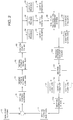
FIG. 1 is a functional schematic depiction of a target signature closed loop control system implementing a first embodiment of the present invention; -
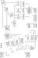
FIG. 2 is a functional schematic depiction of a section average closed loop control system implementing a second embodiment of the present invention; -
FIG. 3 is a functional schematic depiction of a section average and cavity control closed loop control system implementing a third embodiment of the present invention; -
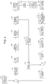
FIG. 4 is a functional schematic depiction of an internal control closed loop control system implementing a fourth embodiment of the present invention; and -
FIG. 5 is a functional schematic depiction of an internal model control closed loop control system implementing a fifth embodiment of the present invention. - The proposed invention utilizes a feedback control loop, an implementation of which is illustrated schematically in
FIG. 1 . A glass formingphysical process 30 createshot glass containers 32. The electromagnetic (EM) energy radiated from, reflected off, or transmitted through thehot glass containers 32 are detected by a multipoint,multispectral measurement system 34, which providespixel data 36 collectively representing eachhot glass container 32 passing the multipoint,multispectral measurement system 34, whichpixel data 36 provide a multipoint measurement of eachhot glass container 32. The measurement may for example be made using an area or line scan camera that is sensitive in the infrared and visible portions of the EM spectrum. Thepixel data 36 corresponds to the measurement emanating from various points of eachhot glass container 32 and/or its immediate surroundings, and this set of m individual pixel values is represented as the m-dimensional vector, x. - The multipoint,
multispectral measurement system 34 may for example be as described in European Patent Application Publication No.EP 2 336 740 A1U.S. Patent No. 8,462,203 , or U.S. Patent Application Publication No.US 2011 0141265 A1 . The multipoint,multispectral measurement system 34 is arranged and configured to monitor radiation emitted by thehot glass containers 32 after they are formed and before they are cooled as they are conveyed away from the I.S. machine. The multipoint,multispectral measurement system 34 includes at least one imaging device for monitoring radiation emitted by thehot glass containers 32 after they are formed and as they are conveyed away from the I.S. machine. - This pixel data vector x is then mathematically transformed in a
signature extraction block 38 to produce a measuredsignature 40, which may be an r-dimensional vector t(x). The length (number of dimensions) r is typically less than m (as discussed subsequently). There are many possible choices for the mathematical transformation accomplished in thesignature extraction block 38, but the general purpose is to provide a reduced dimensional (relative to the original number of pixels) set of values that are correlated with undesirable variations in thehot glass containers 32. - The technique that may be used by the
signature extraction block 38 for this purpose may be Principle Component Analysis (a mathematical procedure that uses orthogonal transformation to convert a set of observations of possibly correlated variables into a set of values of linearly uncorrelated variables called principal components), or through the use of Partial Least Squares regression (a statistical method that finds a linear regression model by projecting the predicted variables and the observable variables to a new space). Both of these approaches will be discussed in detail below. The set of values contained in t(x) will be referred to as the measuredsignature 40. It may be understood that if the variations in the measured signature 40 t(x) can be diminished, then undesirable variations in thehot glass containers 32 will also be reduced. - To accomplish the desired reduction in variability of the measured signature 40 t(x), the measured signature 40 t(x) for each
hot glass container 32 is fed back to acontrol algorithm 42, which computes adjustments to desired thermal formingdurations 44 the purpose of which is to maintain value of t(x) as close as possible to a preferred signature setpoint 46 t(x)target for the signature setpoint. Thepreferred signature setpoint 46 could be chosen, for example, as a value that had previously provided desirablehot glass containers 32. Thepreferred signature setpoint 46 constitutes a preferred target signature. - In order to maintain the measured signature 40 t(x) close to t(x)target, the
control algorithm 42 computes the desired thermal forming durations 44 u (e.g. mold contact time, stretch time, blank contact time) to be applied to the I.S. machine. The thermal forming durations 44 u denotes a length Nu vector of values, where Nu is the number of adjusted values. Many different control algorithms could be used to actually compute the adjustment values. One possibility is to utilize multiple individual Proportional-Integral-Derivative ("PID") control loops with particular process inputs tied to particular elements of the signature vector. A Multiple-Input, Multiple-Output ("MIMO") controller could also be used to account for coupling between the variables. As will be discussed below, one attractive algorithm for this purpose would be a form of what is known in the control literature as internal model control, in which an approximate process model is utilized in the computation of the process adjustments. - Since in general multiple interrelated changes must be made to the timing of the machine events in order to achieve the desired changes in thermal forming duration, a thermal forming
timing adjustment block 48 is used to compute the required detailed timing adjustments. In general, due to constraints of available cycle time, timing sequence requirements, and mechanical interference, it may not be possible to exactly achieve the desired thermal formingdurations 44. It is the function of the thermal formingtiming adjustment block 48 to approximate the desired values within allowable constraints. - Constraints may be derived from externally set inputs such as a
cycle rate 50 or otheradjustable limits 52, or they may be computed using a process model together with data for this process model, which may be contained within the thermal formingtiming adjustment block 48. The computations within the thermal formingtiming adjustment block 48 may take different forms, and may for example include an optimization as discussed withinU.S. Patent Nos. 7,489,983 ,6,722,158 ,6,711,916 ,6,705,120 ,6,705,119 ,6,606,886 ,6,604,386 ,6,604,385 ,6,604,384 , and6,604,383 , which are all assigned to the assignee of the present patent application. Since it may be advantageous for thecontrol algorithm 42 to be aware of constraint values, so as to cause thecontrol algorithm 42 to stay within the allowed limits, these limit values can be communicated to thecontrol algorithm 42 either directly as adjustable limit values 54, or aslimits 56 outputted from the thermal formingtiming adjustment block 48. - The thermal forming
timing adjustment block 48 provides machine timing signals 58 to operate acontainer forming machine 60. Thecontainer forming machine 60 producesmechanical motions 62 which implement the glass formingphysical process 30. Also affecting the glass formingphysical process 30 are toolingthermal boundary conditions 64. Finally, the glass formingphysical process 30 causes glass-tooling interface forces and fluxes 66 which affect the operation of thecontainer forming machine 60. - With regard to the dimensions m, r, and Nu of the pixel data vector, the signature vector, and the process adjustment vector, respectively, it may be noted that in general the number of quantities that can be controlled is limited by the number of adjustable process inputs. That is, we cannot control more than Nu quantities. Therefore, a key aspect of the signature extraction process is to reduce the original m dimensions of pixel data which will generally be greater than Nu down to a smaller number of relevant values that can be controlled with the available number of inputs. In general, it will be required that r is less than or equal to Nu. The number of adjustable inputs Nu is limited by the desired complexity of the control (it may be undesirable to adjust more than a few variables) and also the number of effective control inputs. That is, if there are only a few essential process adjustments that actually effect what we care about in the process, then it isn't beneficial to adjust additional variables.
- The target signature closed loop control system shown in
FIG. 1 provides a high level view of the overall control system for an I.S. machine. In fact, the overall I.S. machine is made of multiple sections, and the overall structure shown inFIG. 1 could be implemented as a set of independent control loops for each section (except if I.S. machine speed control is varied, which would be applicable to the entire I.S. machine). Such a section average control structure is shown in the functional schematic ofFIG. 2 . Referring now toFIG. 2 , this operation can be described as follows. A sectionaverage signature 70 is subtracted from asignature setpoint 72 by asummer 74. The resulting error signal is fed to asection control algorithm 76. Thesignature setpoint 72 constitutes a preferred target signature. - The
section control algorithm 76 computes a set of desired thermal formingdurations 78 that are input to a thermal formingtiming adjustment system 80. The thermal formingtiming adjustment system 80 computes common event timing values 82 for the section. This set of common event timing values 82 is applied to the section. The section, typically produces multiple streams of containers. If there are k mold cavities on the blank side, and k mold cavities on the blow side, we will consider the overall section to be made up of k subprocesses each producing a stream of containers that we designate here as acavity 1process 84, acavity 2process 86, up to acavity k process 88. The hot containers from each of thecavity 1process 84, thecavity 2process 86, and thecavity k process 88, which are respectively shown ascavity 1containers 90,cavity 2containers 92, andcavity k containers 94 are placed onto a flight conveyor (not shown herein) where they, along with the hot containers from the other sections not shown inFIG. 2 , pass a multipoint,multispectral measurement system 96. - As was the case in the system shown in
FIG. 1 , the multipoint,multispectral measurement system 96 shown inFIG. 2 may be as described in European Patent Application Publication No.EP 2 336 740 A1U.S. Patent No. 8,462,203 , and U.S. Patent Application Publication No.US 2011 0141265 A1 . - The multipoint,
multispectral measurement system 96 produces a serial stream ofcontainer pixel vectors 98 corresponding to the passing containers. Thesecontainer pixel vectors 98 are sent to asignature extraction block 100 that transforms the pixel vector from each container to a corresponding reduceddimension signature value 102 vector. The stream of reduced dimension signature values 102 (one for each hot container that has passed the multipoint, multispectral measurement system 96) is provided as an input to asection aggregator 104. Thesection aggregator 104 collects together the reduced dimension signature values 102 corresponding to the last measured machine cycle's production from a given section, and outputs k signature vectors shown as acavity 1signature 106, acavity 2signature 108, and acavity k signature 110, respectively corresponding to the first cavity, the second cavity, up to the kth cavity representing the last measured cycle's production from a given section. The set of k signature vectors including thecavity 1signature 106, thecavity 2signature 108, and thecavity k signature 110 is then averaged by asection averaging block 112 to produce the sectionaverage signature 70, completing the loop. - A further elaboration of the basic structure shown in
FIG. 2 can be implemented to take advantage of adjustable parameters that are available for individual cavities within a section (as opposed to adjustments that are common to the whole section). One possible implementation for a control structure to provide for automatic adjustment to the parameters that are common to all of the cavities as well as those parameters that are individually adjustable is shown inFIG. 3 . Operation of a section average and cavity control system will be described with reference to this figure. - The main section average control loop operates as described with reference to
FIG. 2 , with the same reference numerals being used on the same components of the system. Additionally, a cascade structure has been added, in which the sectionaverage signature 70 provides a setpoint to k individual cavity control algorithms including acavity 1control algorithm 120, acavity 2control algorithm 122, and a cavityk control algorithm 124. Each of the individual control algorithms then adjusts the cavity specific parameters in order to get the individual cavity to match the section average as closely as possible. - Referring to the
cavity 1 control loop, asummer 126 subtracts thecavity 1signature 106 from the sectionaverage signature 70 to produce a resultingsection 1 error signal that is fed to thecavity 1control algorithm 120. Based on thissection 1 error signal, thecavity 1control algorithm 120 computes desired values for thecavity 1 which form an additional part of the desired thermal formingdurations 78. Similarly, referring to thecavity 2 control loop, asummer 128 subtracts thecavity 2signature 108 from the sectionaverage signature 70 to produce a resultingsection 2 error signal that is fed to thecavity 2control algorithm 122. Based on thissection 2 error signal, thecavity 2control algorithm 122 computes desired values for thecavity 2 which also form an additional part of the desired thermal formingdurations 78. Likewise, referring to the cavity k control loop, asummer 130 subtracts thecavity k signature 110 from the sectionaverage signature 70 to produce a resulting section k error signal that is fed to the cavityk control algorithm 124. Based on this section k error signal, the cavityk control algorithm 124 computes desired values for the cavity k which form yet another part of the desired thermal formingdurations 78. - The thermal forming
timing adjustment system 80 uses the values computed by thecavity 1control algorithm 120, thecavity 2control algorithm 122, and the cavityk control algorithm 124, along with the values computed by thesection control algorithm 76, to compute all of the event angles for the section. The common event timing values 82 that are common to the entire section are applied to all of the machine cavities (as was the case in the system ofFIG. 2 ). The cavity specific event values, in contrast, are applied only to the specific cavity of the machine. Thus,cavity 1 event values 132 are applied to thecavity 1process 84,cavity 2 event values 134 are applied to thecavity 2process 86, and cavity k event values 136 are applied to thecavity k process 88. - This use of cavity specific event values in addition to cavity specific event values results in modification to the formation of the containers from the respective cavities, which after being measured and analyzed by the multipoint,
multispectral measurement system 96, thecontainer pixel vectors 98, and thesignature extraction block 100 is manifest as a change to the signatures from each cavity. These additional cavity feedback loop operate to provide fine adjustments to each of the cavities. - Two possible implementations of the signature extraction blocks 38, 100 will now be described. The first implementation utilizes a methodology known as principal component analysis ("PCA"). The second implementation utilizes a methodology known as partial least squares regression. In either case, the overall goal is to take a relatively large number of pixel data points and transform them into a much smaller number of essential variables, which are then controlled. The two approaches differ in their criteria for choosing the essential variables. For the principal component analysis approach, the criterion is to capture as much of the variance in the original set of images as possible using a small number of variables. For the partial least squares regression, the criterion is to choose a representation in which the variability in the transformed image data is maximally correlated with the variability in some set of separately measured quality variables (e.g., from cold end inspection data).
- First, a collection of n container images is gathered. Each container image is represented by a set of m pixel values stored in a length m column vector of pixel values, x[i] where i is the ith container in the collection. An n row by m column matrix X is formed, where the ith row in X is given by x T[i], where the superscript T denotes the transpose. It is desirable to form a new, smaller set of variables to describe the ith container, which is denoted as the length r vector t[k] with r<m. Thus, rather than requiring m values to describe the image of a hot container, we can use only r values to describe the same container.
- Of course, for the technique to be useful, the t[i] values must in some sense contain the important aspects of the images. Specifically, using principal component analysis, the linear combinations of the individual pixel values that have the maximum variance are identified. This captures the key variability in the data in the new variable t[i], which will be referred to here as the signature. The specific computation is performed as follows:
- Define the covariance matrix C xx as:

- Define a new vector t as a linear combination of the columns of x given by:

- The variance is given by:

- Substituting for t from
Equation 2 into Equation 3 gives:
- And substituting for the covariance matrix from
Equation 1 gives:
- Since Cxx is real and symmetric, it can be factored (see for example Strang, Gilbert, Linear Algebra and Its Applications, Academic Press, Second Edition 1980) as:

- Combining Equations 5 and 6 gives:


- Similarly, the next largest variance, for any other direction which is orthogonal to t1 will be in given by w2 aligned with the second eigenvector of Cxx. Continuing with this approach we find that the directions of maximum variance are defined by:

- The largest variance will then occur in the directions given by the columns of T with the greatest amount of variability captured in the first column of T, the next greatest in the second column and so on. Thus we can capture a large proportion of the variability in the data, by retaining only the first r<m columns of T. The value of r needed to capture a given proportion of the total variability depends on the degree of correlation in the original data. For the pixel values in the container images, which are highly correlated with neighboring pixels, we can expect that r will be much less than m (For example, for a 256x256 pixel image we would have m = 65536 (2562=65536) we might need to retain only the first 10 to 20 columns of t to capture a sufficient proportion of the variability. Defining the reduced set of variables, Tr and Vr given by retaining only the first r columns of T and V, we obtained the transformed variables (known as Principal Components) as:

- Once the matrix Vr has been computed, it is saved and then used to transform each subsequent new container image xnew to the new transformed vector tnew using:

- As in
Alternative 1, a collection of n container images is gathered. Each container image is represented by a set of m pixel values stored in a length m column vector of pixel values, x[i] where i is the ith container in the collection. An n row by m column matrix X is then formed where the ith row in X is given by xT[i]. For each of these hot containers, p quality-related variables (e.g. wall thickness, lean, ovality ...) are measured which we denote as the length p column vector y[k]. These are collected together in an n row by p column matrix Y, where the ith row in Y is given by y T[i]. (The elements of y are assumed here to already be appropriately scaled or normalized so that deviations in the individual quality variables are comparable and the columns of Y have zero mean) - It is desired to form a new, smaller set of variables to describe the ith container, which is denoted as the length r vector t[k] with r<m. Thus, rather than requiring m values to describe the image of a container, only r values may be used instead. Of course, for the technique to be useful, the t[i] values must, in some sense, contain the important aspects of the images. Specifically, using partial least squares regression, the linear combinations of the individual pixel values that have the maximum covariance with the quality variables are identified. Intuitively, the aspect of the variability in the images that is most closely related to the variability in the quality is sought, which is the most important matter. The specific computation may be performed as follows.
- The Cross Covariance matrix, Cyx is defined as:

- The directions of maximum covariance between the input (image data) and output (quality data) are being sought. Two particular input and output vectors, p and q, are defined as:

- The covariance cpq between p and q is given by:

- Substituting for p and q from Equation 13 into Equation 14 gives:

- Substituting for the cross covariance matrix Cyx from Equation 12 into Equation 15 gives:

- Let:

- So from Equations 16 and Equations 17:

- Since f is a unit vector, cpq will be maximized when f and r* are collinear. Therefore, define f* as:

- Substituting into Equation 18, the maximal value of the covariance cpq* is given by:

- This can be found by using the singular value decomposition (see Strang, Gilbert, Linear Algebra and Its Applications, Academic Press, Second Edition 1980) to factor Cyx as:

- The internal structure of S is given by:

- Substituting for Cyx from Equation 21 into Equation 17 gives:

- From the structure of the singular value decomposition, it can be seen that the maximum amplification (the largest r* will occur for g1*=v1, the first column of V. The corresponding r, and therefore, f, will be aligned with the first column (singular vector) of W. Similarly, the next largest covariance, for any other direction which is orthogonal to p1=Xg1 will be in given by g2 aligned with the second column of Cyx. Continuing with this approach, it is found that the directions of maximum covariance are defined by the transformed variables:

- To obtain a reduced dimension signature, we retain only the first r singular vectors and singular values with r<m. That is we define Vr and Wr as the first r columns of V and W respectively. Once Vr are obtained, they are saved and new values of the signature vector tnew are computed from new image vectors xnew using:

- It is also possible to advantageously obtain an immediate prediction of the quality variables (which normally isn't available until after the hot containers pass through the Lehr to the cold end inspection, which may be from 30-60 minutes) by regressing the transformed quality variables U as a function of the transformed input variables T.
- Specifically, we use ordinary least squares regression (see Strang, Gilbert, Linear Algebra and Its Applications, Academic Press, Second Edition 1980) to find a matrix of coefficient values B to minimize the error ε:

- Once the matrix B is obtained, new values of the transformed quality variables are obtained from:

- We also have from the definition of Wr:

- Substituting in Equation 27 for unew from Equation 26 and for tnew from Equation 24 gives an overall expression for computing the predicted quality variables from the input image vector:

- The resulting prediction of the quality variables from Equation 28 may be either displayed to the user to provide a monitoring function, or it can be used as a feedback signal in a closed loop control system. The latter use of a computed measurement as a feedback control is commonly referred to as a "soft sensor" (shortened from software sensor).
- Once the container signature signal is obtained (for example using principal component analysis or partial least squares as described above), it may be fed back to a closed loop controller. The responsibility of the closed loop controller is to automatically adjust the process so as to maintain the signature at some desired value (setpoint). Typically, this desired value of the signature will be obtained by first identifying some exemplar set of containers that are considered good. The average signature value for these containers may be calculated and then used as the setpoint. There are many possible control algorithms that could be used to perform the actual closed loop adjustment. In general, any such algorithm must address the multivariable nature of the control problem, in which Nu different forming durations are adjusted to control the r elements of the signature vector.
- To perform the actual closed loop adjustment, an internal model based control system such as the exemplary control system shown schematically in
FIG. 4 may be used. This system follows the internal model control paradigm (as it is called in the control system literature), and utilizes both apredictive process model 140 and aninverse process model 142. Thepredictive process model 140 is used to compute the expected reaction of the container signature to a change in the forming durations. Theinverse process model 142 computes a set of forming durations which, when applied to the system, will provide an approximation of the desired signature. - The closed loop control shown in
FIG. 4 operates as follows. Desiredsignature setpoints 144 are input to theinverse process model 142. Theinverse process model 142 then computes a set of desired formingdurations 146 that should approximately achieve the desired signature values. The desired formingdurations 146 are then provided to a thermal formingtiming adjustment system 148, which transforms the desired formingdurations 146 into event timing ON/OFF angle values 150 using for example using the cycle optimizer technology as discussed withinU.S. Patent Nos. 7,489,983 ,6,722,158 ,6,711,916 ,6,705,120 ,6,705,119 ,6,606,886 ,6,604,386 ,6,604,385 ,6,604,384 , and6,604,383 , which are all assigned to the assignee of the present patent application. - The event timing ON/OFF angle values 150 are then applied to a glass forming
physical process 152. This results inhot containers 154 leaving the glass formingphysical process 152 with a particular thermal state and glass distribution which is then measured by a multipoint,multispectral measurement system 156. As was the case in the systems shown inFIGS. 1-3 , the multipoint,multispectral measurement system 96 shown inFIG. 2 may be as described in European Patent Application Publication No.EP 2 336 740 A1U.S. Patent No. 8,462,203 , and U.S. Patent Application Publication No.US 2011 0141265 A1 . - The multipoint,
multispectral measurement system 156 produces acontainer pixel vector 158 for eachhot container 154 which it sends to asignature extraction block 160. Thesignature extraction block 160 provides a dimensional reduction to produce asignature value 162 for eachhot container 154 using, for example, the principal component analysis or partial least squares algorithms discussed above. The desired formingdurations 146 are also applied to thepredictive process model 140, which computes predictedsignatures 164 of thehot containers 154. The predictedsignature 164 is subtracted from thesignature value 162 in asummer 166, producing amodeling error signal 168. - If the model of the process was perfect, the
modeling error signal 168 would be zero. However, due to numerous actual factors which cannot be perfectly taken into account, themodeling error signal 168 will generally be nonzero. To account for themodeling error signal 168, asummer 170 subtracts themodeling error signal 168 from acontainer signature setpoint 172, producing a modifiedsetpoint 174. It may be understood that if, due to themodeling error signal 168, the current value of thecontainer signature setpoint 172 produces too great a response, then thecontainer signature setpoint 172 may be modified accordingly to ask for a smaller response, or vice versa. Thecontainer signature setpoint 172 constitutes a preferred target signature. - To provide robustness against high frequency modeling errors, and to avoid reaction to spurious high frequency noise, the modified
setpoint 174 is passed through alow pass filter 176, for example a rolling average value, to produce the filtered, modified desiredsignature setpoint 144, thus completing the control loop. For an overall machine control system, multiple internal model controllers each with the same general structure, and operation as described herein with reference toFIG. 4 , would be implemented. There would preferably at least be one internal model controller per section to regulate the section average signature. If individual cavity level adjustments are used, as was the case in the system described with reference toFIG. 3 , then for each section there would be additional internal model controllers assigned to controlling the cavity signatures as well. - A preferred embodiment of the system shown in
FIG. 4 , would utilize a linear, perturbation model of the forming process in which we have:
- The matrix P could be determined empirically by performing a set of tests on an actual section, in which the input parameters u are varied and the resulting perturbations z are recorded. Alternatively, if a sufficiently accurate simulation model was available, the "experiments" could be performed numerically using the simulation model to obtain a linearized model. In either case, using regression techniques, the resulting data could be fit to an equation of the form of Equation 29. The inverse model could then be obtained using the Moore-Penrose pseudoinverse (Penrose, Roger, A Generalized Inverse for Matrices, Proceedings of the Cambridge Philosophical Society 51:406-413, 1955). So that:

- If the number of available input adjustments (elements of the vector u) is less than the number of signature coordinates then in general it will not be possible to achieve an arbitrary set of signature element values. The formulation in
Equation 30 would provide the set of inputs u that would provide an output z that was as close as possible (in a least square error sense) to the desired values. Alternatively, if there are more adjustable parameters then signature elements, then there are multiple possible solutions (multiple values of u). In this case, the Moore-Penrose pseudoinverse has the desirable property of providing the set of inputs u with the smallest magnitude. - In any practical implementation of the above approach, it will be recognized that the process parameter adjustments cannot be arbitrarily large, and thus appropriate limits have to be applied. One approach to providing such limits is shown in
FIG. 5 , in which an internal model control with limits operates as described with reference toFIG. 4 , with the same reference numerals being used on the same components of the system. - Additionally, a minimum / maximum value limits block 180 has been added which provides the allowed minimum or maximum value to the thermal forming
timing adjustment system 148, which then provides an achievable (limited)output signal 182 to thepredictive process model 140. Note that since the same limited output is applied as the event timing ON/OFF angle values 150 to the glass formingphysical process 152 and as the achievable (limited)output signal 182 to thepredictive process model 140, thepredictive process model 140 "knows" that the achievable (limited)output signal 182 is clipped, and the clipping of the achievable (limited)output signal 182 does not result in creating any additional modeling error. - Although the foregoing description of the present invention has been shown and described with reference to particular embodiments and applications thereof, it has been presented for purposes of illustration and description and is not intended to be exhaustive or to limit the invention to the particular embodiments and applications disclosed. It will be apparent to those having ordinary skill in the art that a number of changes, modifications, variations, or alterations to the invention as described herein may be made, none of which depart from the scope of the appended claims. The particular embodiments and applications were chosen and described to provide the best illustration of the principles of the invention and its practical application to thereby enable one of ordinary skill in the art to utilize the invention in various embodiments and with various modifications as are suited to the particular use contemplated. All such changes, modifications, variations, and alterations should therefore be seen as being within the scope of the present invention as determined by the appended claims when interpreted in accordance with the breadth to which they are fairly, legally, and equitably entitled.
Claims (15)
- A system for automatically adjusting the event timing of operations in cavities of a section of an Individual Section, I.S., machine, comprising:a multipoint, multispectral glass container measurement system (96) that is configured to provide container pixel data information (98) indicative of certain measurements of hot glass containers (90, 92, 94) manufactured by the I.S. machine; anda controller configured to produce event timing signals (82) to operate the cavities of the section of the I.S. machine,characterised in that the system further comprises:a signature extraction block (100) that is configured to mathematically transform container pixel data information into a reduced dimensional measured signature (102), the signature extraction block being arranged to produce reduced dimensional measured signatures (106, 108, 110) for each of the cavities in the section of the I.S. machine; anda section averaging block (112) that is arranged to average the reduced dimensional measured signatures (106, 108, 110) for each of the cavities in the section of the I.S. machine to produce a section average measured signature (70) that is provided to the controller,wherein the controller is configured to produce event timing signals (82) to operate the cavities of the section of the I.S. machine in response to the section average measured signature (70) and a preferred target signature (72) to automatically adjust the event timing of operations in the cavities of the section of the I.S. machine to diminish variations in the section average measured signature (70).
- A system as defined in Claim 1, wherein the glass container measurement system is arranged and configured to monitor radiation emitted by hot glass containers (84, 86, 88) after they are formed and before they are cooled as they are conveyed away from the I.S. machine.
- A system as defined in Claim 1 or 2, wherein the glass container measurement system comprises:
at least one imaging device for monitoring radiation emitted by hot glass containers (84, 86, 88) after they are formed and as they are conveyed away from the I.S. machine. - A system as defined in Claim 1, 2, or 3, wherein the signature extraction block uses Principle Component Analysis to mathematically transform container pixel data information (98) into the reduced dimensional measured signature (102).
- A system as defined in Claim 1, 2, or 3, wherein the signature extraction block uses Partial Least Squares regression to mathematically transform container pixel data information into the reduced dimensional measured signature.
- A system as defined in any preceding Claim, wherein the event timing signals produced by the controller comprise desired thermal forming durations (78) including at least mold contact time, stretch time, and blank contact time.
- A system as defined in any preceding Claim, wherein the controller is arranged to limit the event timing signals by adjustable limit values.
- A system as defined in any preceding Claim, wherein, in addition to the section average measured signature (70) being provided to the controller, the system is arranged to provide the reduced dimensional measured signatures (106, 108, 110) for each of the cavities in the section of the I.S. machine to the controller; and wherein the controller is arranged to provide both common event timing signals (82) to all of the sections of the I.S. machine based upon the section average measured signature (70) as well as unique cavity event timing signals (132, 134, 136) based upon the measured signatures for each of the cavities in the section of the I.S. machine to each of the sections of the I.S. machine.
- A system as defined in any preceding Claim, wherein the controller comprises:an inverse process model module (142) arranged to produce a set of forming durations (146) in response to a desired signature setpoint (144) which forming durations are the basis of the event timing of operations applied to the cavities of the section of the I.S. machine which will provide an approximation of the desired signature setpoint; anda predictive process model module (140) arranged to compute a predicted signature (164) which is the calculated response of the measured signature (162) to a change in the forming durations;wherein the controller is arranged to subtract the predicted signature (164) from the measured signature (162) to produce a modeling error signal (168); andwherein the controller is arranged to subtract the modeling error signal (168) from the preferred target signature (172) to produce a modified setpoint (174) which is the basis for the desired signature setpoint (144).
- A system as defined in Claim 9, additionally comprising:
a low pass filter (176) that filters the modified setpoint (174) to produce the desired signature setpoint (144). - A system as defined in Claim 9 or 10, additionally comprising:
a thermal forming timing adjustment system (148) providing the event timing of operations applied to the cavities of the section of the I.S. machine in response to the forming durations (146) produced by the inverse process model module (142). - A system as defined in Claim 11, additionally comprising:a minimum / maximum value limits block (180) arranged to provide allowed minimum or maximum values to the thermal forming timing adjustment system (148);wherein the thermal forming timing adjustment system (148) is arranged to provide an achievable output signal (182) to the predictive process model (140).
- A method of automatically adjusting the event timing of operations in the cavities of a section of an Individual Section, I.S., machine, comprising:providing container pixel data information (98) indicative of certain measurements of hot glass containers (90, 92, 94) manufactured by the I.S. machine with a multipoint, multispectral glass container measurement system (96);mathematically transforming container pixel data information (98) into a reduced dimensional measured signature (102), reduced dimensional measured signatures (106, 108, 110) being produced for each of the cavities in the section of the I.S. machine;averaging the reduced dimensional measured signatures (106, 108, 110) for each of the cavities in the section of the I.S. machine to produce a section average measured signature (70); andproducing event timing signals (82) to operate the cavities of the section of the I.S. machine in response to the section average measured signature (70) and a preferred target signature (72) to automatically adjust the event timing of operations in the cavities of the section of the I.S. machine to diminish variations in the section average measured signature (70).
- A method as defined in Claim 13, comprising providing common event timing signals (82) to all of the sections of the I.S. machine based upon the section average measured signature (70) and unique cavity event timing signals (132, 134, 136) based upon the measured signatures (106, 108, 110) for each of the cavities in the section of the I.S. machine to each of the sections of the I.S. machine.
- A method as defined in Claim 13, wherein the producing event timing signals (82) step comprises diminishing variations between the measured signature and the preferred target signature by determining an error signal and automatically adjusting the event timing based on the error signal.
Priority Applications (1)
| Application Number | Priority Date | Filing Date | Title |
|---|---|---|---|
| PL14191361T PL2874032T3 (en) | 2013-11-07 | 2014-10-31 | Target signature closed loop control system and method |
Applications Claiming Priority (1)
| Application Number | Priority Date | Filing Date | Title |
|---|---|---|---|
| US14/074,260 US9785132B2 (en) | 2013-11-07 | 2013-11-07 | Target signature closed loop control system and method |
Publications (3)
| Publication Number | Publication Date |
|---|---|
| EP2874032A2 EP2874032A2 (en) | 2015-05-20 |
| EP2874032A3 EP2874032A3 (en) | 2015-07-29 |
| EP2874032B1 true EP2874032B1 (en) | 2020-05-06 |
Family
ID=51868807
Family Applications (1)
| Application Number | Title | Priority Date | Filing Date |
|---|---|---|---|
| EP14191361.6A Active EP2874032B1 (en) | 2013-11-07 | 2014-10-31 | Target signature closed loop control system and method |
Country Status (6)
| Country | Link |
|---|---|
| US (1) | US9785132B2 (en) |
| EP (1) | EP2874032B1 (en) |
| JP (1) | JP6534804B2 (en) |
| ES (1) | ES2796024T3 (en) |
| PL (1) | PL2874032T3 (en) |
| PT (1) | PT2874032T (en) |
Families Citing this family (6)
| Publication number | Priority date | Publication date | Assignee | Title |
|---|---|---|---|---|
| US9458043B2 (en) * | 2013-11-15 | 2016-10-04 | Emhart Glass S.A. | Utilization of wall thickness measurement in combination with thermal imaging of containers |
| US11795093B2 (en) | 2018-03-29 | 2023-10-24 | Emhart Glass S.A. | Multivariable vertical glass distribution control using soft sensor and methods |
| CN108595892A (en) * | 2018-05-11 | 2018-09-28 | 南京林业大学 | Soft-measuring modeling method based on time difference model |
| JP7062577B2 (en) * | 2018-11-21 | 2022-05-06 | 株式会社日立製作所 | Manufacturing condition identification system and method |
| DE102021121305A1 (en) | 2021-08-17 | 2023-02-23 | Krones Aktiengesellschaft | Production plant for the manufacture, treatment and/or filling of containers and methods for the production control and/or plant specification thereof |
| FR3130024B1 (en) * | 2021-12-08 | 2024-04-26 | Konatic | Device for stereovision of a hot translucent container |
Citations (6)
| Publication number | Priority date | Publication date | Assignee | Title |
|---|---|---|---|---|
| EP0873975A2 (en) | 1997-04-21 | 1998-10-28 | Owens-Brockway Glass Container Inc. | Gob arrival timing in an individual section machine glassware forming system |
| US20080013821A1 (en) | 2004-05-20 | 2008-01-17 | Macgregor John F | Method For Controlling The Appearance Of Products And Process Performance By Image Analysis |
| US20110141265A1 (en) | 2009-12-10 | 2011-06-16 | Mark Edwin Holtkamp | System and Method for Monitoring Hot Glass Containers to Enhance Their Quality and Control the Forming Process |
| US20120211331A1 (en) | 2011-02-23 | 2012-08-23 | Simon Jonathan S | System and Method for Controlling Pusher Parameters to Adjust the Placement of Glass Containers on the Conveyor |
| US20120226378A1 (en) | 2011-03-03 | 2012-09-06 | Simon Jonathan S | Closed Loop Cyclic Timing Optimizer Control System And Method |
| US20130178952A1 (en) | 2010-06-28 | 2013-07-11 | Precitec Itm Gmbh | Method for closed-loop controlling a laser processing operation and laser material processing head using the same |
Family Cites Families (18)
| Publication number | Priority date | Publication date | Assignee | Title |
|---|---|---|---|---|
| US6584805B1 (en) * | 1993-08-24 | 2003-07-01 | Coors Brewing Company | Hot bottle inspection apparatus |
| JP4192394B2 (en) * | 2000-04-14 | 2008-12-10 | オムロン株式会社 | air conditioner |
| US6604384B2 (en) | 2001-04-10 | 2003-08-12 | Emhart Glass, S.A. | Control for an I.S. machine |
| US6722158B2 (en) | 2001-04-10 | 2004-04-20 | Emhart Glass S.A. | Control for an I.S. machine |
| US6604385B2 (en) | 2001-04-10 | 2003-08-12 | Emhart Glass, S.A. | Control for an I.S. machine |
| US6604383B2 (en) | 2001-04-10 | 2003-08-12 | Emhart Glass, S.A. | Control for an I.S. machine |
| US6604386B2 (en) | 2001-04-10 | 2003-08-12 | Emhart Glass, S.A. | Control for an I.S. machine |
| US6705120B2 (en) | 2001-04-10 | 2004-03-16 | Emhart Glass S.A. | Control for an I.S. machine |
| US6711916B2 (en) | 2001-04-10 | 2004-03-30 | Emhart Glass S.A. | Control for an I.S. machine |
| US6705119B2 (en) | 2001-04-10 | 2004-03-16 | Emhart Glass S.A. | Control for an I. S. machine |
| US6606886B2 (en) | 2001-04-10 | 2003-08-19 | Emhart Glass, S.A. | Control for an I.S. machine |
| US7489983B2 (en) | 2004-11-03 | 2009-02-10 | Emhart Glass S.A. | Control for an I.S. machine |
| US7685840B2 (en) * | 2006-03-24 | 2010-03-30 | Corning Incorporated | Method of minimizing distortion in a sheet of glass |
| EP2336740B1 (en) | 2009-12-10 | 2014-02-12 | Emhart Glass S.A. | Method and system for monitoring a glass container forming process |
| US9580345B2 (en) * | 2011-04-12 | 2017-02-28 | Emhart Glass S.A. | Closed loop blank mold temperature control system and method |
| JP5808605B2 (en) * | 2011-08-17 | 2015-11-10 | 株式会社日立製作所 | Abnormality detection / diagnosis method and abnormality detection / diagnosis system |
| DE102012002016B4 (en) | 2012-02-03 | 2017-10-05 | Heye International Gmbh | Method for controlling the process parameters of a glass forming machine and use of the method |
| FR2988846B1 (en) * | 2012-03-27 | 2014-04-11 | Msc & Sgcc | METHOD AND INSTALLATION FOR MEASURING THE DISTRIBUTION OF GLASS IN CONTAINERS |
-
2013
- 2013-11-07 US US14/074,260 patent/US9785132B2/en active Active
-
2014
- 2014-10-29 JP JP2014220261A patent/JP6534804B2/en not_active Expired - Fee Related
- 2014-10-31 EP EP14191361.6A patent/EP2874032B1/en active Active
- 2014-10-31 PT PT141913616T patent/PT2874032T/en unknown
- 2014-10-31 ES ES14191361T patent/ES2796024T3/en active Active
- 2014-10-31 PL PL14191361T patent/PL2874032T3/en unknown
Patent Citations (6)
| Publication number | Priority date | Publication date | Assignee | Title |
|---|---|---|---|---|
| EP0873975A2 (en) | 1997-04-21 | 1998-10-28 | Owens-Brockway Glass Container Inc. | Gob arrival timing in an individual section machine glassware forming system |
| US20080013821A1 (en) | 2004-05-20 | 2008-01-17 | Macgregor John F | Method For Controlling The Appearance Of Products And Process Performance By Image Analysis |
| US20110141265A1 (en) | 2009-12-10 | 2011-06-16 | Mark Edwin Holtkamp | System and Method for Monitoring Hot Glass Containers to Enhance Their Quality and Control the Forming Process |
| US20130178952A1 (en) | 2010-06-28 | 2013-07-11 | Precitec Itm Gmbh | Method for closed-loop controlling a laser processing operation and laser material processing head using the same |
| US20120211331A1 (en) | 2011-02-23 | 2012-08-23 | Simon Jonathan S | System and Method for Controlling Pusher Parameters to Adjust the Placement of Glass Containers on the Conveyor |
| US20120226378A1 (en) | 2011-03-03 | 2012-09-06 | Simon Jonathan S | Closed Loop Cyclic Timing Optimizer Control System And Method |
Non-Patent Citations (7)
| Title |
|---|
| ANONYMOUS: "Hot End Imaging", MSC, 8 June 2007 (2007-06-08), pages 1, XP055778310, Retrieved from the Internet <URL:https://web.archive.orq/web/20070608115743> |
| ANONYMOUS: "Hot imaging and cold inspection meet quality demands together", GLASS, November 2006 (2006-11-01), pages 1 - 2, XP055778301 |
| ANONYMOUS: "I-CARE User Manual MSC Inspection worldwide", MSC, 2008, pages 1 - 160, XP055778305 |
| ANONYMOUS: "L'imagerie en bout chaud : I-Care", VERRE, vol. 10, no. 6, December 2004 (2004-12-01), pages 1 - 3, XP055778318 |
| ANONYMOUS: "Process control and flexibility", GLASS WORLDWIDE, 2012, pages 1 - 3, XP055778361 |
| C.DUCHESNEA, J.J.LIU, J.F.MACGREGORCD: "Multivariate image analysis in the process industries: A review", CHEMOMETRICS AND INTELLIGENT LABORATORY SYSTEMS, 16 April 2012 (2012-04-16), pages 117 - 128, XP055778410 |
| MACGREGOR J. F., T.KOURTI, J.LIU, J.BRADLEY, K.DUNNH.YU2: "Multivariate methods for the analysis of ...", IFAC PROCEEDINGS VOLUMES, vol. 40, no. 11, 2007, pages 193 - 198, XP055778393, Retrieved from the Internet <URL:www.sciencedirect.com/journal/ifac-proceedings-volumes/vol/40/issue/11> |
Also Published As
| Publication number | Publication date |
|---|---|
| EP2874032A2 (en) | 2015-05-20 |
| US20150127134A1 (en) | 2015-05-07 |
| US9785132B2 (en) | 2017-10-10 |
| JP2015090710A (en) | 2015-05-11 |
| EP2874032A3 (en) | 2015-07-29 |
| PT2874032T (en) | 2020-05-28 |
| ES2796024T3 (en) | 2020-11-25 |
| JP6534804B2 (en) | 2019-06-26 |
| PL2874032T3 (en) | 2020-10-19 |
Similar Documents
| Publication | Publication Date | Title |
|---|---|---|
| EP2874032B1 (en) | Target signature closed loop control system and method | |
| Stubbs et al. | Fault detection in dynamic processes using a simplified monitoring-specific CVA state space modelling approach | |
| Zhang et al. | Process data modeling using modified kernel partial least squares | |
| WO2002067297A2 (en) | Run-to-run control method for proportional-integral-derivative (pid) controller tuning for rapid thermal processing (rtp) | |
| EP2495630B1 (en) | Closed loop cyclic timing optimizer control system and method | |
| Kestener et al. | Generalizing the wavelet-based multifractal formalism to random vector fields: application to three-dimensional turbulence velocity and vorticity data | |
| WO2017104305A1 (en) | Failure diagnosis device and failure diagnosis method | |
| Yan et al. | Event-triggered sequential fusion estimation with correlated noises | |
| EP2492244B1 (en) | System and method for controlling pusher parameters to adjust the placement of glass containers on a conveyor | |
| CN102754040A (en) | Method for controlling an injection molding process | |
| Montgomery et al. | Ensemble predictions of the 2012 US presidential election | |
| Böhm et al. | Trajectory planning and tracking control for the temperature distribution in a deep drawing tool | |
| Lin et al. | Pose estimation in industrial machine vision systems under sensing dynamics: A statistical learning approach | |
| Jiang et al. | Control-oriented mechatronic design and data analytics for quality-assured laser powder bed fusion additive manufacturing | |
| Thieullen et al. | Application of Principal Components Analysis to improve fault detection and diagnosis on semiconductor manufacturing equipment | |
| JP6402760B2 (en) | Shape control method and apparatus in rolling mill | |
| CN105302197B (en) | The mobile heating control system and method for a kind of temperature intelligent regulation and control | |
| Su et al. | Monitoring pH-shift reactive crystallization of L-Glutamic acid using moving window MPCA | |
| Chen et al. | Performance monitoring of MPCA-based control for multivariable batch control processes | |
| Fu et al. | Support vector regression method for boundary value problems | |
| Zhiyu et al. | A new desirability function based method for multi-response robust parameter design | |
| JP2011226855A (en) | Heat transfer analyzer and heat transfer analysis method | |
| Halawa | Dynamics of closed-loop control system with Smith's controller | |
| Pin et al. | Adaptive task-space control of strip flatness in multiroll mill stands | |
| Kim et al. | An optimal control formulation for dual control problems |
Legal Events
| Date | Code | Title | Description |
|---|---|---|---|
| PUAI | Public reference made under article 153(3) epc to a published international application that has entered the european phase |
Free format text: ORIGINAL CODE: 0009012 |
|
| 17P | Request for examination filed |
Effective date: 20141031 |
|
| AK | Designated contracting states |
Kind code of ref document: A2 Designated state(s): AL AT BE BG CH CY CZ DE DK EE ES FI FR GB GR HR HU IE IS IT LI LT LU LV MC MK MT NL NO PL PT RO RS SE SI SK SM TR |
|
| AX | Request for extension of the european patent |
Extension state: BA ME |
|
| PUAL | Search report despatched |
Free format text: ORIGINAL CODE: 0009013 |
|
| AK | Designated contracting states |
Kind code of ref document: A3 Designated state(s): AL AT BE BG CH CY CZ DE DK EE ES FI FR GB GR HR HU IE IS IT LI LT LU LV MC MK MT NL NO PL PT RO RS SE SI SK SM TR |
|
| AX | Request for extension of the european patent |
Extension state: BA ME |
|
| RIC1 | Information provided on ipc code assigned before grant |
Ipc: G05B 19/042 20060101AFI20150625BHEP Ipc: G06T 7/00 20060101ALI20150625BHEP Ipc: G05B 19/418 20060101ALI20150625BHEP Ipc: G01J 5/00 20060101ALI20150625BHEP Ipc: G05B 19/04 20060101ALI20150625BHEP |
|
| R17P | Request for examination filed (corrected) |
Effective date: 20160122 |
|
| RBV | Designated contracting states (corrected) |
Designated state(s): AL AT BE BG CH CY CZ DE DK EE ES FI FR GB GR HR HU IE IS IT LI LT LU LV MC MK MT NL NO PL PT RO RS SE SI SK SM TR |
|
| STAA | Information on the status of an ep patent application or granted ep patent |
Free format text: STATUS: EXAMINATION IS IN PROGRESS |
|
| 17Q | First examination report despatched |
Effective date: 20190311 |
|
| TPAC | Observations filed by third parties |
Free format text: ORIGINAL CODE: EPIDOSNTIPA |
|
| GRAP | Despatch of communication of intention to grant a patent |
Free format text: ORIGINAL CODE: EPIDOSNIGR1 |
|
| STAA | Information on the status of an ep patent application or granted ep patent |
Free format text: STATUS: GRANT OF PATENT IS INTENDED |
|
| INTG | Intention to grant announced |
Effective date: 20191129 |
|
| TPAC | Observations filed by third parties |
Free format text: ORIGINAL CODE: EPIDOSNTIPA |
|
| GRAS | Grant fee paid |
Free format text: ORIGINAL CODE: EPIDOSNIGR3 |
|
| GRAA | (expected) grant |
Free format text: ORIGINAL CODE: 0009210 |
|
| STAA | Information on the status of an ep patent application or granted ep patent |
Free format text: STATUS: THE PATENT HAS BEEN GRANTED |
|
| AK | Designated contracting states |
Kind code of ref document: B1 Designated state(s): AL AT BE BG CH CY CZ DE DK EE ES FI FR GB GR HR HU IE IS IT LI LT LU LV MC MK MT NL NO PL PT RO RS SE SI SK SM TR |
|
| REG | Reference to a national code |
Ref country code: GB Ref legal event code: FG4D |
|
| REG | Reference to a national code |
Ref country code: CH Ref legal event code: EP Ref country code: AT Ref legal event code: REF Ref document number: 1267790 Country of ref document: AT Kind code of ref document: T Effective date: 20200515 |
|
| REG | Reference to a national code |
Ref country code: IE Ref legal event code: FG4D |
|
| REG | Reference to a national code |
Ref country code: DE Ref legal event code: R096 Ref document number: 602014064859 Country of ref document: DE Ref country code: PT Ref legal event code: SC4A Ref document number: 2874032 Country of ref document: PT Date of ref document: 20200528 Kind code of ref document: T Free format text: AVAILABILITY OF NATIONAL TRANSLATION Effective date: 20200520 |
|
| REG | Reference to a national code |
Ref country code: LT Ref legal event code: MG4D |
|
| REG | Reference to a national code |
Ref country code: NL Ref legal event code: MP Effective date: 20200506 |
|
| PG25 | Lapsed in a contracting state [announced via postgrant information from national office to epo] |
Ref country code: NO Free format text: LAPSE BECAUSE OF FAILURE TO SUBMIT A TRANSLATION OF THE DESCRIPTION OR TO PAY THE FEE WITHIN THE PRESCRIBED TIME-LIMIT Effective date: 20200806 Ref country code: FI Free format text: LAPSE BECAUSE OF FAILURE TO SUBMIT A TRANSLATION OF THE DESCRIPTION OR TO PAY THE FEE WITHIN THE PRESCRIBED TIME-LIMIT Effective date: 20200506 Ref country code: GR Free format text: LAPSE BECAUSE OF FAILURE TO SUBMIT A TRANSLATION OF THE DESCRIPTION OR TO PAY THE FEE WITHIN THE PRESCRIBED TIME-LIMIT Effective date: 20200807 Ref country code: IS Free format text: LAPSE BECAUSE OF FAILURE TO SUBMIT A TRANSLATION OF THE DESCRIPTION OR TO PAY THE FEE WITHIN THE PRESCRIBED TIME-LIMIT Effective date: 20200906 Ref country code: SE Free format text: LAPSE BECAUSE OF FAILURE TO SUBMIT A TRANSLATION OF THE DESCRIPTION OR TO PAY THE FEE WITHIN THE PRESCRIBED TIME-LIMIT Effective date: 20200506 Ref country code: LT Free format text: LAPSE BECAUSE OF FAILURE TO SUBMIT A TRANSLATION OF THE DESCRIPTION OR TO PAY THE FEE WITHIN THE PRESCRIBED TIME-LIMIT Effective date: 20200506 |
|
| REG | Reference to a national code |
Ref country code: ES Ref legal event code: FG2A Ref document number: 2796024 Country of ref document: ES Kind code of ref document: T3 Effective date: 20201125 |
|
| PG25 | Lapsed in a contracting state [announced via postgrant information from national office to epo] |
Ref country code: BG Free format text: LAPSE BECAUSE OF FAILURE TO SUBMIT A TRANSLATION OF THE DESCRIPTION OR TO PAY THE FEE WITHIN THE PRESCRIBED TIME-LIMIT Effective date: 20200806 Ref country code: LV Free format text: LAPSE BECAUSE OF FAILURE TO SUBMIT A TRANSLATION OF THE DESCRIPTION OR TO PAY THE FEE WITHIN THE PRESCRIBED TIME-LIMIT Effective date: 20200506 Ref country code: RS Free format text: LAPSE BECAUSE OF FAILURE TO SUBMIT A TRANSLATION OF THE DESCRIPTION OR TO PAY THE FEE WITHIN THE PRESCRIBED TIME-LIMIT Effective date: 20200506 Ref country code: HR Free format text: LAPSE BECAUSE OF FAILURE TO SUBMIT A TRANSLATION OF THE DESCRIPTION OR TO PAY THE FEE WITHIN THE PRESCRIBED TIME-LIMIT Effective date: 20200506 |
|
| REG | Reference to a national code |
Ref country code: AT Ref legal event code: MK05 Ref document number: 1267790 Country of ref document: AT Kind code of ref document: T Effective date: 20200506 |
|
| PG25 | Lapsed in a contracting state [announced via postgrant information from national office to epo] |
Ref country code: NL Free format text: LAPSE BECAUSE OF FAILURE TO SUBMIT A TRANSLATION OF THE DESCRIPTION OR TO PAY THE FEE WITHIN THE PRESCRIBED TIME-LIMIT Effective date: 20200506 Ref country code: AL Free format text: LAPSE BECAUSE OF FAILURE TO SUBMIT A TRANSLATION OF THE DESCRIPTION OR TO PAY THE FEE WITHIN THE PRESCRIBED TIME-LIMIT Effective date: 20200506 |
|
| PG25 | Lapsed in a contracting state [announced via postgrant information from national office to epo] |
Ref country code: DK Free format text: LAPSE BECAUSE OF FAILURE TO SUBMIT A TRANSLATION OF THE DESCRIPTION OR TO PAY THE FEE WITHIN THE PRESCRIBED TIME-LIMIT Effective date: 20200506 Ref country code: AT Free format text: LAPSE BECAUSE OF FAILURE TO SUBMIT A TRANSLATION OF THE DESCRIPTION OR TO PAY THE FEE WITHIN THE PRESCRIBED TIME-LIMIT Effective date: 20200506 Ref country code: SM Free format text: LAPSE BECAUSE OF FAILURE TO SUBMIT A TRANSLATION OF THE DESCRIPTION OR TO PAY THE FEE WITHIN THE PRESCRIBED TIME-LIMIT Effective date: 20200506 Ref country code: EE Free format text: LAPSE BECAUSE OF FAILURE TO SUBMIT A TRANSLATION OF THE DESCRIPTION OR TO PAY THE FEE WITHIN THE PRESCRIBED TIME-LIMIT Effective date: 20200506 Ref country code: RO Free format text: LAPSE BECAUSE OF FAILURE TO SUBMIT A TRANSLATION OF THE DESCRIPTION OR TO PAY THE FEE WITHIN THE PRESCRIBED TIME-LIMIT Effective date: 20200506 |
|
| REG | Reference to a national code |
Ref country code: DE Ref legal event code: R026 Ref document number: 602014064859 Country of ref document: DE |
|
| PLBI | Opposition filed |
Free format text: ORIGINAL CODE: 0009260 |
|
| PLAX | Notice of opposition and request to file observation + time limit sent |
Free format text: ORIGINAL CODE: EPIDOSNOBS2 |
|
| PG25 | Lapsed in a contracting state [announced via postgrant information from national office to epo] |
Ref country code: SK Free format text: LAPSE BECAUSE OF FAILURE TO SUBMIT A TRANSLATION OF THE DESCRIPTION OR TO PAY THE FEE WITHIN THE PRESCRIBED TIME-LIMIT Effective date: 20200506 |
|
| 26 | Opposition filed |
Opponent name: BOTTERO S.P.A. Effective date: 20210208 |
|
| PG25 | Lapsed in a contracting state [announced via postgrant information from national office to epo] |
Ref country code: SI Free format text: LAPSE BECAUSE OF FAILURE TO SUBMIT A TRANSLATION OF THE DESCRIPTION OR TO PAY THE FEE WITHIN THE PRESCRIBED TIME-LIMIT Effective date: 20200506 |
|
| REG | Reference to a national code |
Ref country code: CH Ref legal event code: PL |
|
| PLBB | Reply of patent proprietor to notice(s) of opposition received |
Free format text: ORIGINAL CODE: EPIDOSNOBS3 |
|
| PG25 | Lapsed in a contracting state [announced via postgrant information from national office to epo] |
Ref country code: MC Free format text: LAPSE BECAUSE OF FAILURE TO SUBMIT A TRANSLATION OF THE DESCRIPTION OR TO PAY THE FEE WITHIN THE PRESCRIBED TIME-LIMIT Effective date: 20200506 Ref country code: LU Free format text: LAPSE BECAUSE OF NON-PAYMENT OF DUE FEES Effective date: 20201031 |
|
| REG | Reference to a national code |
Ref country code: BE Ref legal event code: MM Effective date: 20201031 |
|
| PG25 | Lapsed in a contracting state [announced via postgrant information from national office to epo] |
Ref country code: BE Free format text: LAPSE BECAUSE OF NON-PAYMENT OF DUE FEES Effective date: 20201031 Ref country code: CH Free format text: LAPSE BECAUSE OF NON-PAYMENT OF DUE FEES Effective date: 20201031 Ref country code: LI Free format text: LAPSE BECAUSE OF NON-PAYMENT OF DUE FEES Effective date: 20201031 |
|
| PG25 | Lapsed in a contracting state [announced via postgrant information from national office to epo] |
Ref country code: IE Free format text: LAPSE BECAUSE OF NON-PAYMENT OF DUE FEES Effective date: 20201031 |
|
| PG25 | Lapsed in a contracting state [announced via postgrant information from national office to epo] |
Ref country code: TR Free format text: LAPSE BECAUSE OF FAILURE TO SUBMIT A TRANSLATION OF THE DESCRIPTION OR TO PAY THE FEE WITHIN THE PRESCRIBED TIME-LIMIT Effective date: 20200506 Ref country code: MT Free format text: LAPSE BECAUSE OF FAILURE TO SUBMIT A TRANSLATION OF THE DESCRIPTION OR TO PAY THE FEE WITHIN THE PRESCRIBED TIME-LIMIT Effective date: 20200506 Ref country code: CY Free format text: LAPSE BECAUSE OF FAILURE TO SUBMIT A TRANSLATION OF THE DESCRIPTION OR TO PAY THE FEE WITHIN THE PRESCRIBED TIME-LIMIT Effective date: 20200506 |
|
| PG25 | Lapsed in a contracting state [announced via postgrant information from national office to epo] |
Ref country code: MK Free format text: LAPSE BECAUSE OF FAILURE TO SUBMIT A TRANSLATION OF THE DESCRIPTION OR TO PAY THE FEE WITHIN THE PRESCRIBED TIME-LIMIT Effective date: 20200506 |
|
| PLCK | Communication despatched that opposition was rejected |
Free format text: ORIGINAL CODE: EPIDOSNREJ1 |
|
| APBM | Appeal reference recorded |
Free format text: ORIGINAL CODE: EPIDOSNREFNO |
|
| APBP | Date of receipt of notice of appeal recorded |
Free format text: ORIGINAL CODE: EPIDOSNNOA2O |
|
| APAH | Appeal reference modified |
Free format text: ORIGINAL CODE: EPIDOSCREFNO |
|
| APBQ | Date of receipt of statement of grounds of appeal recorded |
Free format text: ORIGINAL CODE: EPIDOSNNOA3O |
|
| REG | Reference to a national code |
Ref country code: DE Ref legal event code: R082 Ref document number: 602014064859 Country of ref document: DE Representative=s name: MEISSNER BOLTE PATENTANWAELTE RECHTSANWAELTE P, DE |
|
| P01 | Opt-out of the competence of the unified patent court (upc) registered |
Effective date: 20230607 |
|
| PLAB | Opposition data, opponent's data or that of the opponent's representative modified |
Free format text: ORIGINAL CODE: 0009299OPPO |
|
| R26 | Opposition filed (corrected) |
Opponent name: BOTTERO S.P.A. Effective date: 20210208 |
|
| APAH | Appeal reference modified |
Free format text: ORIGINAL CODE: EPIDOSCREFNO |
|
| PGFP | Annual fee paid to national office [announced via postgrant information from national office to epo] |
Ref country code: GB Payment date: 20231027 Year of fee payment: 10 |
|
| PGFP | Annual fee paid to national office [announced via postgrant information from national office to epo] |
Ref country code: ES Payment date: 20231102 Year of fee payment: 10 |
|
| PGFP | Annual fee paid to national office [announced via postgrant information from national office to epo] |
Ref country code: PT Payment date: 20231003 Year of fee payment: 10 Ref country code: IT Payment date: 20231023 Year of fee payment: 10 Ref country code: FR Payment date: 20231025 Year of fee payment: 10 Ref country code: DE Payment date: 20231027 Year of fee payment: 10 Ref country code: CZ Payment date: 20231005 Year of fee payment: 10 |
|
| PGFP | Annual fee paid to national office [announced via postgrant information from national office to epo] |
Ref country code: PL Payment date: 20231003 Year of fee payment: 10 |