EP2336740A1 - Method and system for monitoring and controlling a glass container forming process - Google Patents
Method and system for monitoring and controlling a glass container forming process Download PDFInfo
- Publication number
- EP2336740A1 EP2336740A1 EP09075545A EP09075545A EP2336740A1 EP 2336740 A1 EP2336740 A1 EP 2336740A1 EP 09075545 A EP09075545 A EP 09075545A EP 09075545 A EP09075545 A EP 09075545A EP 2336740 A1 EP2336740 A1 EP 2336740A1
- Authority
- EP
- European Patent Office
- Prior art keywords
- glass container
- curve
- intensity
- forming
- glass
- Prior art date
- Legal status (The legal status is an assumption and is not a legal conclusion. Google has not performed a legal analysis and makes no representation as to the accuracy of the status listed.)
- Granted
Links
- 239000011521 glass Substances 0.000 title claims abstract description 156
- 238000000034 method Methods 0.000 title claims abstract description 60
- 238000012544 monitoring process Methods 0.000 title claims abstract description 11
- 230000005855 radiation Effects 0.000 claims abstract description 47
- 238000005259 measurement Methods 0.000 claims abstract description 29
- 238000012935 Averaging Methods 0.000 claims description 6
- 238000004519 manufacturing process Methods 0.000 abstract description 13
- 238000001816 cooling Methods 0.000 description 9
- 230000007423 decrease Effects 0.000 description 3
- 239000000779 smoke Substances 0.000 description 3
- 239000005356 container glass Substances 0.000 description 2
- 230000007812 deficiency Effects 0.000 description 2
- 238000001514 detection method Methods 0.000 description 2
- 238000007664 blowing Methods 0.000 description 1
- -1 camera settings Substances 0.000 description 1
- 238000009826 distribution Methods 0.000 description 1
- 239000000463 material Substances 0.000 description 1
- 230000007246 mechanism Effects 0.000 description 1
- 239000000203 mixture Substances 0.000 description 1
- 239000006060 molten glass Substances 0.000 description 1
- 238000003825 pressing Methods 0.000 description 1
- 230000001360 synchronised effect Effects 0.000 description 1
Images


Classifications
-
- C—CHEMISTRY; METALLURGY
- C03—GLASS; MINERAL OR SLAG WOOL
- C03B—MANUFACTURE, SHAPING, OR SUPPLEMENTARY PROCESSES
- C03B9/00—Blowing glass; Production of hollow glass articles
- C03B9/30—Details of blowing glass; Use of materials for the moulds
- C03B9/40—Gearing or controlling mechanisms specially adapted for glass-blowing machines
- C03B9/41—Electric or electronic systems
-
- G—PHYSICS
- G05—CONTROLLING; REGULATING
- G05B—CONTROL OR REGULATING SYSTEMS IN GENERAL; FUNCTIONAL ELEMENTS OF SUCH SYSTEMS; MONITORING OR TESTING ARRANGEMENTS FOR SUCH SYSTEMS OR ELEMENTS
- G05B11/00—Automatic controllers
- G05B11/01—Automatic controllers electric
- G05B11/011—Automatic controllers electric details of the correcting means
-
- G—PHYSICS
- G01—MEASURING; TESTING
- G01J—MEASUREMENT OF INTENSITY, VELOCITY, SPECTRAL CONTENT, POLARISATION, PHASE OR PULSE CHARACTERISTICS OF INFRARED, VISIBLE OR ULTRAVIOLET LIGHT; COLORIMETRY; RADIATION PYROMETRY
- G01J5/00—Radiation pyrometry, e.g. infrared or optical thermometry
- G01J5/0003—Radiation pyrometry, e.g. infrared or optical thermometry for sensing the radiant heat transfer of samples, e.g. emittance meter
-
- G—PHYSICS
- G01—MEASURING; TESTING
- G01J—MEASUREMENT OF INTENSITY, VELOCITY, SPECTRAL CONTENT, POLARISATION, PHASE OR PULSE CHARACTERISTICS OF INFRARED, VISIBLE OR ULTRAVIOLET LIGHT; COLORIMETRY; RADIATION PYROMETRY
- G01J5/00—Radiation pyrometry, e.g. infrared or optical thermometry
- G01J5/02—Constructional details
- G01J5/025—Interfacing a pyrometer to an external device or network; User interface
-
- G—PHYSICS
- G01—MEASURING; TESTING
- G01J—MEASUREMENT OF INTENSITY, VELOCITY, SPECTRAL CONTENT, POLARISATION, PHASE OR PULSE CHARACTERISTICS OF INFRARED, VISIBLE OR ULTRAVIOLET LIGHT; COLORIMETRY; RADIATION PYROMETRY
- G01J5/00—Radiation pyrometry, e.g. infrared or optical thermometry
- G01J5/02—Constructional details
- G01J5/08—Optical arrangements
- G01J5/0846—Optical arrangements having multiple detectors for performing different types of detection, e.g. using radiometry and reflectometry channels
-
- G—PHYSICS
- G01—MEASURING; TESTING
- G01J—MEASUREMENT OF INTENSITY, VELOCITY, SPECTRAL CONTENT, POLARISATION, PHASE OR PULSE CHARACTERISTICS OF INFRARED, VISIBLE OR ULTRAVIOLET LIGHT; COLORIMETRY; RADIATION PYROMETRY
- G01J5/00—Radiation pyrometry, e.g. infrared or optical thermometry
- G01J5/10—Radiation pyrometry, e.g. infrared or optical thermometry using electric radiation detectors
-
- G—PHYSICS
- G01—MEASURING; TESTING
- G01N—INVESTIGATING OR ANALYSING MATERIALS BY DETERMINING THEIR CHEMICAL OR PHYSICAL PROPERTIES
- G01N25/00—Investigating or analyzing materials by the use of thermal means
- G01N25/72—Investigating presence of flaws
-
- G—PHYSICS
- G01—MEASURING; TESTING
- G01N—INVESTIGATING OR ANALYSING MATERIALS BY DETERMINING THEIR CHEMICAL OR PHYSICAL PROPERTIES
- G01N33/00—Investigating or analysing materials by specific methods not covered by groups G01N1/00 - G01N31/00
- G01N33/38—Concrete; ceramics; glass; bricks
- G01N33/386—Glass
-
- G—PHYSICS
- G05—CONTROLLING; REGULATING
- G05B—CONTROL OR REGULATING SYSTEMS IN GENERAL; FUNCTIONAL ELEMENTS OF SUCH SYSTEMS; MONITORING OR TESTING ARRANGEMENTS FOR SUCH SYSTEMS OR ELEMENTS
- G05B21/00—Systems involving sampling of the variable controlled
-
- G—PHYSICS
- G01—MEASURING; TESTING
- G01J—MEASUREMENT OF INTENSITY, VELOCITY, SPECTRAL CONTENT, POLARISATION, PHASE OR PULSE CHARACTERISTICS OF INFRARED, VISIBLE OR ULTRAVIOLET LIGHT; COLORIMETRY; RADIATION PYROMETRY
- G01J5/00—Radiation pyrometry, e.g. infrared or optical thermometry
- G01J2005/0077—Imaging
-
- G—PHYSICS
- G01—MEASURING; TESTING
- G01N—INVESTIGATING OR ANALYSING MATERIALS BY DETERMINING THEIR CHEMICAL OR PHYSICAL PROPERTIES
- G01N21/00—Investigating or analysing materials by the use of optical means, i.e. using sub-millimetre waves, infrared, visible or ultraviolet light
- G01N21/84—Systems specially adapted for particular applications
- G01N2021/845—Objects on a conveyor
-
- G—PHYSICS
- G01—MEASURING; TESTING
- G01N—INVESTIGATING OR ANALYSING MATERIALS BY DETERMINING THEIR CHEMICAL OR PHYSICAL PROPERTIES
- G01N21/00—Investigating or analysing materials by the use of optical means, i.e. using sub-millimetre waves, infrared, visible or ultraviolet light
- G01N21/84—Systems specially adapted for particular applications
- G01N21/88—Investigating the presence of flaws or contamination
- G01N21/8851—Scan or image signal processing specially adapted therefor, e.g. for scan signal adjustment, for detecting different kinds of defects, for compensating for structures, markings, edges
- G01N2021/8887—Scan or image signal processing specially adapted therefor, e.g. for scan signal adjustment, for detecting different kinds of defects, for compensating for structures, markings, edges based on image processing techniques
-
- G—PHYSICS
- G01—MEASURING; TESTING
- G01N—INVESTIGATING OR ANALYSING MATERIALS BY DETERMINING THEIR CHEMICAL OR PHYSICAL PROPERTIES
- G01N21/00—Investigating or analysing materials by the use of optical means, i.e. using sub-millimetre waves, infrared, visible or ultraviolet light
- G01N21/84—Systems specially adapted for particular applications
- G01N21/88—Investigating the presence of flaws or contamination
- G01N21/90—Investigating the presence of flaws or contamination in a container or its contents
- G01N2021/9063—Hot-end container inspection
Definitions
- the present invention relates to a method and system for monitoring and controlling a glass container forming process.
- the forming process is accomplished by a forming machine which may contain multiple independent sections, each section consisting of at least one forming station.
- the method comprises the steps of measuring radiation emitted by each hot glass container immediately after the forming machine. Based on these measurements, information and control signals may be generated to adjust the glass container forming process in order to improve the quality of the glass containers and by doing so reduce the number of bad glass containers produced.
- a system of this type is disclosed in the European Patent EP 1525469 B1 , which describes a system for analyzing and monitoring a production process for glass products.
- the system is sensitive to radiation in the Near Infra Red (NIR) region solely and it measures the NIR radiation of hot glass products, determines the average radiation intensity for at least two measurement regions, compares this average intensity with a reference value, compares deviations between the measurement regions, and, based on this comparison, when necessary generates an error signal.
- NIR Near Infra Red
- a cooling curve is calculated and used as a reference to compensate for the difference in the amount of radiation of glass products due to different cooling times.
- the system may generate error signals even when there is a change in the amount of radiation which is not brought about due to a change in the forming process, but is due instead to changes in the various conditions and parameters, such as, among others, the ambient temperature, ambient humidity, production speed, cooling air temperature, cooling air humidity, glass material composition, camera settings, smoke and dirt in the air, pollution of the optics, and container weight.
- Another disadvantage of the system is that when starting the production of a glass container which has been produced earlier, the above mentioned conditions and parameters may have been changed, in which case the reference values and/or cooling curves used for the previous production may not be useful for the current production. In such a case, each time a new reference and/or a cooling curve is required, which will lengthen the start up time and is therefore not desirable.
- a primary object of the present invention is to provide a method for monitoring and controlling a glass container forming process which is independent of the above mentioned conditions and parameters and with which it is possible to produce glass containers with a high and constant quality.
- Another object of the present invention is to generate a unique master reference which serves as a quality reference for the type of container produced, in order to produce glass containers at each forming station with the same quality depicted by this master reference and to decrease the time necessary to start up the forming process.
- This unique master reference may be stored and used to monitor and control the same forming machine or another forming machine producing the same particular glass container type at a different location.
- Yet a further object of the present invention is to eliminate the requirement of having an operator monitoring the process constantly by instead controlling the forming machine automatically.
- the present invention relates to a method for monitoring and controlling a glass container forming process.
- the method comprises the steps of measuring radiation emitted by hot glass containers immediately after the forming machine with a camera sensitive to the radiation emitted by the hot glass containers.
- the glass container image generated by the camera is arranged in a finite number of image lines, each image line having a finite number of pixels characterized in that the method further comprises the following steps for each glass container measured from each forming station:
- a cooling curve is used to compensate for these different cooling times.
- this cooling curve is based on absolute intensity values, and is therefore sensitive to changes in above-mentioned conditions and parameters.
- the intensity-ratio curve of the hot glass containers compensates for the temperature of the glass container. When a glass container from a forming station further away (lower temperature) has the same glass distribution as a glass container from a forming station closer to the measurement unit, the intensity-ratio curves from both glass containers will be the same.
- the intensity-ratio curve of a hot glass container can further be compared with a master reference.
- the master reference is unique for each particular glass container type, and thus serves as a quality measure for each particular glass container type.
- a preferred embodiment of method according to the present invention further comprises the following step:
- Averaging the intensity-ratio curves over a number of hot glass containers includes summing the intensity-ratio curves of a number of glass containers and dividing this sum by the number of glass containers.
- Glass containers may be averaged over a period of time, from one or more selected stations, over a number of production cycles, or over just one production cycle.
- This master reference curve can be saved in order to be used when producing the same container type at a later time, either on the same forming machine or on a different forming machine. It can also be used to analyze and compare the current production performance with a past production. If desired, the master reference curve can be continuously updated which may result in an even better quality being achieved for the same container.
- the relative difference curve easily shows how much and where the intensity-ratio curve of a glass container deviates from the master reference curve.
- the relative difference curve can be displayed for each forming station in order to show the quality of the glass containers produced at the forming station. When the quality of a produced glass container is high, the relative difference curve will be close to zero. When the relative difference curves of all containers from all stations are close to zero, the quality of all containers produced by the forming machine will be high and substantially equal.
- the tolerance curve may be constant, tolerating the same amount of deviation for every location on said container.
- the values of the tolerance curve may also be dependant on the location on said container. By doing so, one is for instance able to allow less deviation from the master reference curve for one or more areas of the container where the glass thickness is critical.
- the tolerance values may be positive as well as negative.
- control unit controls the forming process of each forming station by a number of process parameters.
- another preferred embodiment of method according to the present invention comprises the following step:
- the adjustment of the process may be performed automatically and shortly after the detection of a change or an error in the forming process. The adjustment will occur in such a manner that the relative difference curves substantially decreases to zero.
- the measurement may be carried out at any wavelength at which a hot glass container emits radiation. Nevertheless, since the amount of radiation of container glass not only depends on the glass temperature but also on the glass thickness for wavelengths smaller than 3.0 microns, the measurement will be more accurate at wavelengths smaller than 3.0 microns, especially when analyzing relatively thicker glass containers. Therefore, a preferred embodiment method according to the present invention is characterized in that said measurement occurs for wavelengths of between 0.7 and 3.0 microns.
- the present invention also relates to an analytical system for monitoring and controlling a glass container forming process.
- the system comprises at least one measurement unit to measure radiation emitted by each hot glass container immediately after the forming machine.
- the measurement unit may comprise a line-scan or area camera sensitive to the radiation emitted by the hot glass containers.
- the glass container image generated by the camera is arranged in a finite number of image lines, with each image line having a finite number of pixels.
- the processor unit provides calculations, comparisons, and communications with other units, wherein the processor unit is further programmed to carry out the following steps:
- the processor unit is programmed such that it performs above mentioned operation in order to make the measured values of intensities independent not only of changes in parameters and conditions of the environment, process, and measuring equipment, but also independent of the forming station where a hot glass container originates from.
- an average intensity-ratio curve is acquired which is unique for a particular type of glass container.
- the average intensity-ratio curve may serve as a master reference for the quality of glass containers of that particular type. It can also be utilized for another forming machine at a different location when producing the same type of glass container with the same quality requirements.
- the quality of a hot glass container may be analyzed and the possible cause of a deficiency in the forming process may be indicated. Doing this, one can easily see how much and where the intensity ratio curve of a hot glass container deviates from the master reference curve.
- the relative difference curve can be displayed for each forming station in order to show the quality of the produced glass containers and to show the performance of the forming process. When the quality of a produced glass container is high, the relative difference curve will be zero or negligibly small.
- the alarm signal may be used, for instance, to reject glass containers which have an unacceptable quality.
- the tolerance curve may be constant or it may be variable dependant on the location on the glass container.
- the processor unit sends the relative difference curve of each glass container to the forming control unit, and the forming control unit, when necessary, adjusts one or more process parameters. This way, an automatic adjustment of process parameters is feasible shortly after the detection of an error or any detectable deficiency.
- the measurement unit may be sensitive to any wavelength at which a hot glass container emits radiation. Nevertheless, since the amount of radiation of container glass depends on the glass temperature and the glass thickness for wavelengths smaller than 3.0 microns, the measurement will be more accurate at wavelengths smaller than 3.0 microns, especially when analyzing relatively thicker glass containers. Therefore, a preferred embodiment of analytical system according to the present invention is characterized in that the measurement unit is sensitive to wavelengths of between 0.7 and 3.0 microns. More specifically, the measurement unit comprises a Short Wave Infra Red (SWIR) camera, for example a 512 or 1024 pixels line-scan or area SWIR camera.
- SWIR Short Wave Infra Red
- FIG 1 shows an embodiment of the system where the glass container forming machine (1) contains six independent sections (S1), (S2), ... (S6), each of which contains two forming stations (2a) and (2b).
- the forming machine (1) produces twelve glass containers (4).
- Two molten glass gobs (5a) and (5b) are formed at the same moment by the feeder unit (6) and are loaded into the so-called blank moulds (2a) and (2b).
- Each section (S1), (S2), ... (S6) of the forming machine (1) in this embodiment contains two blank moulds (2a) and (2b) in which pre-containers or parisons are formed by pressing or blowing depending on the process type (press-blow or blow-blow).
- the formed parisons are transferred to the so-called blow moulds (3a) and (3b) where the parisons are blown into the final shape of the glass containers (4).
- the mechanisms of the forming machine (1) and the feeder unit (6) are controlled by the control unit (7) through lines (14) and (15), respectively.
- the glass containers (4) are transported by a conveyor belt (13) through a measurement unit (9) which takes images of the hot glass containers (4) and sends these images to a processor unit (10) through a line (11).
- a measurement unit (9) which takes images of the hot glass containers (4) and sends these images to a processor unit (10) through a line (11).
- the number of measurement units (9) may be increased depending on the circumstances and the accuracy to be achieved. However, even with one measurement unit, the achieved accuracy is fairly high.
- the measurement unit (9), an area camera in this embodiment, is preferably sensitive to Short Wave Infra Red (SWIR) radiation.
- SWIR Short Wave Infra Red
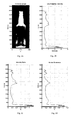
- the image taken by the camera of the hot glass container (4) shown in FIG. 2a preferably contains 512 image-lines, with each image-line preferably containing 200 pixels.
- the processor unit (10) determines for each glass container (4) the total intensity by summing the intensities of all the pixels in the container image.
- the total intensity of the container shown in Fig. 2a has a value of 553.
- the processor unit (10) determines the line radiation intensities by summing for each image-line the intensities of all 200 pixels.
- the line radiation intensities belonging to the glass container image of FIG. 2a is shown in FIG. 2b .
- the processor unit (10) determines the intensity-ratio curve by dividing the line radiation intensities by the total intensity, as shown hereunder: I tot .
- I tot, s the total intensity value of a container image, originating from station (s)
- the intensity-ratio values are expressed in percentages for clarity.
- the intensity-ratio curve depicted in FIG. 2c belongs to the glass container shown in FIG. 2a . Obviously, the order in which these steps occur can be changed as long as the same results are achieved.
- the processor unit (10) determines a master reference curve by averaging intensity-ratio curves from a number of glass containers (4) from all or certain selected forming stations. This master reference curve is unique for the glass container type produced.
- I reference , y ⁇ I ratio , y , s / N
- I reference,y the master reference curve value for line (y).
- N number of glass containers (4) taken into account
- the master reference curve may be stored and used later to decrease the time necessary to start up the production of the particular container (4) on the same or on another forming machine.
- the master reference curve belonging to the container type in this example is shown in FIG. 2d .
- the master reference curve is shown together with the intensity-ratio curve of FIG. 2c .
- ⁇ I s.y the relative difference value at line (y) of a container image originating from the station (s).
- the relative difference curve shows how much and where the intensity-ratio curve of a glass container deviates from the master reference curve.
- the processor unit (10) may display on a connected monitor (not shown) for each forming station the relative difference curve in order to show the quality of the glass containers produced at the forming station.
- FIG. 2f the relative difference curve is shown for the glass container of FIG. 2a with the corresponding intensity-ratio curve shown in FIG. 2c .
- the relative difference curve in FIG. 2f shows a positive deviation in the upper part of the container and a negative deviation in the lower part of the container, indicating too much glass in the upper part of the container and too little glass in the lower part of the container.
- the relative difference curve will be close to zero at every point for high quality glass containers.
- the alarm signal may, for example, be used in order to reject glass containers which have an unacceptable quality.
- the negative tolerance values are set at -30% and the positive tolerance values are set at +30%.
- an alarm signal is generated because the relative difference values for line 300 through line 380 exceed the positive tolerance values.
- the processor unit (10) may send the relative difference curve from each forming station to the control unit (7) over line (12).
- the control unit (7) adjusts the appropriate process parameters until the relative difference curve for each forming station is close to zero. This is then achieved without the need to have an operator monitoring the process continuously.
- the processor unit (10) is synchronized with the forming machine (1) and with conveyor belt (13) in such a way that processor unit (10) knows from which forming station each glass container (4) originates.
Abstract
Description
- The present invention relates to a method and system for monitoring and controlling a glass container forming process. The forming process is accomplished by a forming machine which may contain multiple independent sections, each section consisting of at least one forming station. The method comprises the steps of measuring radiation emitted by each hot glass container immediately after the forming machine. Based on these measurements, information and control signals may be generated to adjust the glass container forming process in order to improve the quality of the glass containers and by doing so reduce the number of bad glass containers produced.
- A system of this type is disclosed in the European Patent
EP 1525469 B1 , which describes a system for analyzing and monitoring a production process for glass products. The system is sensitive to radiation in the Near Infra Red (NIR) region solely and it measures the NIR radiation of hot glass products, determines the average radiation intensity for at least two measurement regions, compares this average intensity with a reference value, compares deviations between the measurement regions, and, based on this comparison, when necessary generates an error signal. In addition, a cooling curve is calculated and used as a reference to compensate for the difference in the amount of radiation of glass products due to different cooling times. - However, the system may generate error signals even when there is a change in the amount of radiation which is not brought about due to a change in the forming process, but is due instead to changes in the various conditions and parameters, such as, among others, the ambient temperature, ambient humidity, production speed, cooling air temperature, cooling air humidity, glass material composition, camera settings, smoke and dirt in the air, pollution of the optics, and container weight.
- These conditions and parameters can drastically alter the measured radiation intensities depending on, for example, whether operating at day or night, different seasons, the production location, and/or the forming machine.
- Consequently, an operator should always be present to monitor the measurement results and the generated error signals carefully, to check the conditions and parameters, and to adjust reference values in order to compensate for continuously changing conditions and parameters. From a practical point of view this is a very undesirable requirement, since labor costs are high and the forming process occurs in an extremely hot and noisy environment where labor conditions are quite unfavorable.
- Another disadvantage of the system is that when starting the production of a glass container which has been produced earlier, the above mentioned conditions and parameters may have been changed, in which case the reference values and/or cooling curves used for the previous production may not be useful for the current production. In such a case, each time a new reference and/or a cooling curve is required, which will lengthen the start up time and is therefore not desirable.
- A primary object of the present invention is to provide a method for monitoring and controlling a glass container forming process which is independent of the above mentioned conditions and parameters and with which it is possible to produce glass containers with a high and constant quality.
- Another object of the present invention is to generate a unique master reference which serves as a quality reference for the type of container produced, in order to produce glass containers at each forming station with the same quality depicted by this master reference and to decrease the time necessary to start up the forming process. This unique master reference may be stored and used to monitor and control the same forming machine or another forming machine producing the same particular glass container type at a different location.
- Yet a further object of the present invention is to eliminate the requirement of having an operator monitoring the process constantly by instead controlling the forming machine automatically.
- To achieve the above mentioned objects, the present invention relates to a method for monitoring and controlling a glass container forming process. The method comprises the steps of measuring radiation emitted by hot glass containers immediately after the forming machine with a camera sensitive to the radiation emitted by the hot glass containers. The glass container image generated by the camera is arranged in a finite number of image lines, each image line having a finite number of pixels characterized in that the method further comprises the following steps for each glass container measured from each forming station:
- a. determining a total radiation intensity for each glass container by summing the intensity values of all the pixels in all the image lines for such glass container;
- b. determining a line radiation intensity for each image line for each glass container by summing the intensity values of all the pixels in such image line for such glass container; and
- c. determining an intensity-ratio curve for each glass container by dividing the line radiation intensities for each image line of such glass container by the total radiation intensity for such glass container.
- The above mentioned problem of changing conditions and parameters is compensated for by dividing the line radiation intensities with the total radiation intensity. This can be explained as follows. When, for example, the radiation of a hot glass container is partly absorbed by some smoke in the air, the line radiation intensities gets lower and the total intensity gets lower. However, the result of dividing the line radiation intensities by the total intensity will not change (the intensity-ratio curve will not change). Obviously, this would not have been the case when, as in the prior art, absolute values of the intensity are used.
- Glass containers originating from forming stations close to the measurement unit when compared to containers from forming stations further away travel a shorter distance to the measurement unit taking less time, and thus cool down less and consequently will have a higher temperature. In the prior art, a cooling curve is used to compensate for these different cooling times. However, this cooling curve is based on absolute intensity values, and is therefore sensitive to changes in above-mentioned conditions and parameters. According to the present invention, the intensity-ratio curve of the hot glass containers compensates for the temperature of the glass container. When a glass container from a forming station further away (lower temperature) has the same glass distribution as a glass container from a forming station closer to the measurement unit, the intensity-ratio curves from both glass containers will be the same.
- The intensity-ratio curve of a hot glass container can further be compared with a master reference. The master reference is unique for each particular glass container type, and thus serves as a quality measure for each particular glass container type. In order to acquire this unique master reference, a preferred embodiment of method according to the present invention further comprises the following step:
- d. determining a master reference curve by averaging the intensity-ratio curves over a predetermined number of hot glass containers from all or a selected number of forming stations.
- Averaging the intensity-ratio curves over a number of hot glass containers includes summing the intensity-ratio curves of a number of glass containers and dividing this sum by the number of glass containers. Glass containers may be averaged over a period of time, from one or more selected stations, over a number of production cycles, or over just one production cycle.
- One may obtain various master reference curves with different forming machine settings, from which the one having to the best performance, producing the best quality of glass containers, may be selected. This master reference curve can be saved in order to be used when producing the same container type at a later time, either on the same forming machine or on a different forming machine. It can also be used to analyze and compare the current production performance with a past production. If desired, the master reference curve can be continuously updated which may result in an even better quality being achieved for the same container.
- Another preferred embodiment of method according to the present invention comprises the following step:
- e. determining a relative difference curve for each hot glass container by subtracting said master reference curve from said intensity-ratio curve of each hot glass container and dividing the result by said master reference curve.
- The relative difference curve easily shows how much and where the intensity-ratio curve of a glass container deviates from the master reference curve. The relative difference curve can be displayed for each forming station in order to show the quality of the glass containers produced at the forming station. When the quality of a produced glass container is high, the relative difference curve will be close to zero. When the relative difference curves of all containers from all stations are close to zero, the quality of all containers produced by the forming machine will be high and substantially equal.
- Another preferred embodiment of method according to the present invention comprises the following steps:
- f. comparing said relative difference curve with a predetermined tolerance curve.
- g. generating an alarm signal if said relative difference curve exceeds said tolerance curve in at least one point.
- By comparing the relative difference curve with a tolerance curve and generating an alarm signal if the difference exceeds the tolerance curve, one can easily determine whether the quality of glass containers produced by a forming station is acceptable or if it has degraded to such a degree that the container is of an inferior quality and therefore unacceptable.
- The tolerance curve may be constant, tolerating the same amount of deviation for every location on said container. However, the values of the tolerance curve may also be dependant on the location on said container. By doing so, one is for instance able to allow less deviation from the master reference curve for one or more areas of the container where the glass thickness is critical. Furthermore, the tolerance values may be positive as well as negative.
- The control unit controls the forming process of each forming station by a number of process parameters. In order to control the forming process automatically, another preferred embodiment of method according to the present invention comprises the following step:
- h. sending said relative difference curve of each hot glass container to said control unit.
- By sending the relative difference curves of glass containers from each forming station to the control unit, the adjustment of the process may be performed automatically and shortly after the detection of a change or an error in the forming process. The adjustment will occur in such a manner that the relative difference curves substantially decreases to zero.
- The measurement may be carried out at any wavelength at which a hot glass container emits radiation. Nevertheless, since the amount of radiation of container glass not only depends on the glass temperature but also on the glass thickness for wavelengths smaller than 3.0 microns, the measurement will be more accurate at wavelengths smaller than 3.0 microns, especially when analyzing relatively thicker glass containers. Therefore, a preferred embodiment method according to the present invention is characterized in that said measurement occurs for wavelengths of between 0.7 and 3.0 microns.
- The present invention also relates to an analytical system for monitoring and controlling a glass container forming process. The system comprises at least one measurement unit to measure radiation emitted by each hot glass container immediately after the forming machine. The measurement unit may comprise a line-scan or area camera sensitive to the radiation emitted by the hot glass containers. The glass container image generated by the camera is arranged in a finite number of image lines, with each image line having a finite number of pixels. The processor unit provides calculations, comparisons, and communications with other units, wherein the processor unit is further programmed to carry out the following steps:
- a. determining a total radiation intensity for each glass container by summing the intensity values of all the pixels in all the image lines for such glass container;
- b. determining a line radiation intensity for each image line for each glass container by summing the intensity values of all the pixels in such image line for such glass container; and
- c. determining an intensity-ratio curve for each glass container by dividing the line radiation intensities for each image line of such glass container by the total radiation intensity for such glass container.
- The processor unit is programmed such that it performs above mentioned operation in order to make the measured values of intensities independent not only of changes in parameters and conditions of the environment, process, and measuring equipment, but also independent of the forming station where a hot glass container originates from.
- A further preferred embodiment of the analytical system according to the present invention is characterized in that the processor unit is further programmed to carry out the following step:
- d. determining a master reference curve by averaging the intensity-ratio curves over a predetermined number of hot glass containers from all or a selected number of forming stations.
- By summing the intensity-ratio curves of a number of hot glass containers and dividing the sum by the number of containers, an average intensity-ratio curve is acquired which is unique for a particular type of glass container. The average intensity-ratio curve may serve as a master reference for the quality of glass containers of that particular type. It can also be utilized for another forming machine at a different location when producing the same type of glass container with the same quality requirements.
- Another preferred embodiment of analytical system according to the present invention is characterized in that the processor unit is further programmed to carry out the following step:
- e. determining a relative difference curve for each hot glass container by subtracting said master reference curve from said intensity-ratio curve of each hot glass container and dividing the result by said master reference curve.
- By determining the relative difference curve, the quality of a hot glass container may be analyzed and the possible cause of a deficiency in the forming process may be indicated. Doing this, one can easily see how much and where the intensity ratio curve of a hot glass container deviates from the master reference curve. The relative difference curve can be displayed for each forming station in order to show the quality of the produced glass containers and to show the performance of the forming process. When the quality of a produced glass container is high, the relative difference curve will be zero or negligibly small.
- Another preferred embodiment of analytical system according to the present invention is characterized in that the processor unit is further programmed to carry out the following step:
- f. comparing said relative difference curve of each hot glass container with a predetermined tolerance curve;
- g. generating an alarm signal if said relative difference curve exceeds said tolerance curve in at least one point.
- Doing this, it can easily be determined whether the quality of the produced glass containers at a forming station is acceptable or not. The alarm signal may be used, for instance, to reject glass containers which have an unacceptable quality. The tolerance curve may be constant or it may be variable dependant on the location on the glass container.
- Still another preferred embodiment of analytical system according to the present invention is characterized in that the processor unit is further programmed to carry out the following step:
- h. sending said relative difference curve of each hot glass container to the forming control unit.
- The processor unit sends the relative difference curve of each glass container to the forming control unit, and the forming control unit, when necessary, adjusts one or more process parameters. This way, an automatic adjustment of process parameters is feasible shortly after the detection of an error or any detectable deficiency.
- The measurement unit may be sensitive to any wavelength at which a hot glass container emits radiation. Nevertheless, since the amount of radiation of container glass depends on the glass temperature and the glass thickness for wavelengths smaller than 3.0 microns, the measurement will be more accurate at wavelengths smaller than 3.0 microns, especially when analyzing relatively thicker glass containers. Therefore, a preferred embodiment of analytical system according to the present invention is characterized in that the measurement unit is sensitive to wavelengths of between 0.7 and 3.0 microns. More specifically, the measurement unit comprises a Short Wave Infra Red (SWIR) camera, for example a 512 or 1024 pixels line-scan or area SWIR camera.
- The invention will be explained in more detail with reference to the appended drawings in which:
-
FIG. 1 shows a schematic view of a forming machine and an embodiment of the analytical system, -
FIG. 2a shows an image of a glass container, -
FIG. 2b shows the line radiation intensities for the glass container shown inFIG. 1 , -
FIG. 2c shows an intensity-ratio curve for the glass container shown inFIG. 1 , -
FIG. 2d shows a master reference curve for the glass container shown inFIG. 1 , -
FIG. 2e shows a master reference curve together with the intensity-ratio curve for the glass container shown inFIG. 1 , and -
FIG. 2f shows a relative difference curve for the glass container shown inFIG. 1 . -
FIG 1 . shows an embodiment of the system where the glass container forming machine (1) contains six independent sections (S1), (S2), ... (S6), each of which contains two forming stations (2a) and (2b). In one production cycle, the forming machine (1) produces twelve glass containers (4). Two molten glass gobs (5a) and (5b) are formed at the same moment by the feeder unit (6) and are loaded into the so-called blank moulds (2a) and (2b). Each section (S1), (S2), ... (S6) of the forming machine (1) in this embodiment contains two blank moulds (2a) and (2b) in which pre-containers or parisons are formed by pressing or blowing depending on the process type (press-blow or blow-blow). The formed parisons are transferred to the so-called blow moulds (3a) and (3b) where the parisons are blown into the final shape of the glass containers (4). The mechanisms of the forming machine (1) and the feeder unit (6) are controlled by the control unit (7) through lines (14) and (15), respectively. The glass containers (4) are transported by a conveyor belt (13) through a measurement unit (9) which takes images of the hot glass containers (4) and sends these images to a processor unit (10) through a line (11). Although in this embodiment one measurement unit (9) is used, the number of measurement units (9) may be increased depending on the circumstances and the accuracy to be achieved. However, even with one measurement unit, the achieved accuracy is fairly high. - The measurement unit (9), an area camera in this embodiment, is preferably sensitive to Short Wave Infra Red (SWIR) radiation. The image taken by the camera of the hot glass container (4) shown in
FIG. 2a preferably contains 512 image-lines, with each image-line preferably containing 200 pixels. - The processor unit (10) determines for each glass container (4) the total intensity by summing the intensities of all the pixels in the container image. The total intensity of the container shown in
Fig. 2a has a value of 553. Next, the processor unit (10) determines the line radiation intensities by summing for each image-line the intensities of all 200 pixels. The line radiation intensities belonging to the glass container image ofFIG. 2a is shown inFIG. 2b . Now, the processor unit (10), determines the intensity-ratio curve by dividing the line radiation intensities by the total intensity, as shown hereunder:
Where:
Itot, s = the total intensity value of a container image, originating from station (s),
Ix,y, s = the intensity value of pixel (x,y) of the container image, originating from station (s) with (y) representing an image-line containing 200 (x) pixels, x=1..200, y=1..512, s=1..12,
Iy, s = the radiation intensity value for image-line (y) of a container image, originating from station (s),
Iratio, y, s = the intensity-ratio value for image-line (y) of a container image, originating from station (s). - The intensity-ratio values are expressed in percentages for clarity. The intensity-ratio curve depicted in
FIG. 2c belongs to the glass container shown inFIG. 2a . Obviously, the order in which these steps occur can be changed as long as the same results are achieved. One can easily see that, for example, an attenuation α of the radiation received from the glass container (4) caused by an ambient parameter (for example smoke in the air) has no influence on the intensity-ratio curve:
- Next, the processor unit (10) determines a master reference curve by averaging intensity-ratio curves from a number of glass containers (4) from all or certain selected forming stations. This master reference curve is unique for the glass container type produced.
- The values of the master reference curve are derived as illustrated below:

Where:
I reference,y = the master reference curve value for line (y).
N = number of glass containers (4) taken into account - The master reference curve may be stored and used later to decrease the time necessary to start up the production of the particular container (4) on the same or on another forming machine. The master reference curve belonging to the container type in this example is shown in
FIG. 2d . InFIG. 2e , the master reference curve is shown together with the intensity-ratio curve ofFIG. 2c . - The processor unit (10) next determines the relative difference curve by subtracting the master reference curve from the intensity-ratio curve and dividing the difference by the master reference curve. This is illustrated hereunder:

- Where:
Δ Is.y = the relative difference value at line (y) of a container image originating from the station (s). - The relative difference curve shows how much and where the intensity-ratio curve of a glass container deviates from the master reference curve. The processor unit (10) may display on a connected monitor (not shown) for each forming station the relative difference curve in order to show the quality of the glass containers produced at the forming station. In
FIG. 2f , the relative difference curve is shown for the glass container ofFIG. 2a with the corresponding intensity-ratio curve shown inFIG. 2c . - In this specific example the relative difference curve in
FIG. 2f shows a positive deviation in the upper part of the container and a negative deviation in the lower part of the container, indicating too much glass in the upper part of the container and too little glass in the lower part of the container. The relative difference curve will be close to zero at every point for high quality glass containers. - Subsequently, the processor unit (10) compares the relative difference curve with predetermined tolerance curves and generates an alarm signal if a relative difference value exceeds the corresponding tolerance value. This is illustrated hereunder: Alarm if:

I T-, y = the negative tolerance value for line (y);
I T+, y = the positive tolerance value for line (y). - The alarm signal may, for example, be used in order to reject glass containers which have an unacceptable quality. In
FIG. 2f the negative tolerance values are set at -30% and the positive tolerance values are set at +30%. InFIG. 2f an alarm signal is generated because the relative difference values forline 300 through line 380 exceed the positive tolerance values. - In order to adjust the forming process automatically, the processor unit (10) may send the relative difference curve from each forming station to the control unit (7) over line (12). The control unit (7) adjusts the appropriate process parameters until the relative difference curve for each forming station is close to zero. This is then achieved without the need to have an operator monitoring the process continuously.
- The processor unit (10) is synchronized with the forming machine (1) and with conveyor belt (13) in such a way that processor unit (10) knows from which forming station each glass container (4) originates.
- The embodiment described above is intended solely to serve as an example, and in no way is intended to restrict the invention. A person skilled in the art given knowledge of this invention will rapidly be able to accomplish other embodiments. Therefore, any variation on the theme and methodology of accomplishing the same that are not described herein would be considered under the scope of the present invention.
Claims (13)
- A method for monitoring and controlling a glass container forming process wherein said forming process is accomplished by a forming machine (1) which contains multiple independent sections each having at least one forming station at which glass containers (4) are formed, comprising the steps of measuring radiation emitted by hot glass containers (4) immediately after said forming machine (1) with a measurement unit (9) sensitive to the radiation emitted by the hot glass containers (4), wherein the measurement unit (9) generates an image of each hot glass container (4) which is arranged in a finite number of image lines, each image line having a finite number of pixels, characterized in that said method further comprises the following steps for each glass container (4) measured from each forming station:a. determining a total radiation intensity for each glass container by summing the intensity values of all the pixels in all the image lines for such glass container;b. determining a line radiation intensity for each image line for each glass container by summing the intensity values of all the pixels in such image line for such glass container; andc. determining an intensity-ratio curve for each glass container by dividing the line radiation intensities for each image line of such glass container by the total radiation intensity for such glass container.
- A method according to Claim 1, characterized in that said method further comprises the following step in order to generate a unique reference with which each glass container from each forming station is compared:d. Determining a master reference curve by averaging said intensity-ratio curves over a predetermined number of said glass containers (4) originating from all or from a selected number of forming stations.
- A method according to Claim 2, characterized in that said method further comprises the following step in order to generate information about the difference between the glass containers produced in a forming station with said master reference curve:e. Determining a relative difference curve for each glass container (4) from each forming station by subtracting said master reference curve from said intensity-ratio curve and dividing the result by said master reference curve.
- A method according to Claim 3, characterized in that said method further comprises the following steps:f. comparing said relative difference curve of each hot glass container (4) with predetermined tolerance curves;g. generating an alarm signal if said relative difference curve exceeds said tolerance curves in at least one point.
- A method according to any of the preceding claims, characterized in that said method further comprises the following step in order to control the forming process automatically:a. sending said relative difference curve of each hot glass container (4) to said control unit (7).
- A method according to any of the preceding claims, characterized in that said measurement occurs for wavelengths of between 0.7 and 3.0 microns.
- A system for monitoring and controlling a glass container forming process, wherein said forming process is accomplished by a forming machine (1) which is controlled by a control unit (7) and which contains multiple independent sections each having at least one forming station at which glass containers (4) are formed, comprising at least one measurement unit (9) sensitive to the radiation emitted by the hot glass containers (4) immediately after said forming machine (1), generating images of each hot glass container (4) arranged in a finite number of image lines, each image line having a finite number of pixels, and a processor unit (10) to provide calculations, comparisons and communications with other units, characterized in that said processor unit (10) is further programmed to carry out the following steps for each glass container (4) measured from each forming station:a. determining a total radiation intensity for each glass container by summing the intensity values of all the pixels in all the image lines for such glass container;b. determining a line radiation intensity for each image line for each glass container by summing the intensity values of all the pixels in such image line for such glass container; andc. determining an intensity-ratio curve for each glass container by dividing the line radiation intensities for each image line of such glass container by the total radiation intensity for such glass container.
- A system according to Claim 7, characterized in that, said processor unit (10) is further programmed to carry out the following step:d. determining a master reference curve by averaging said intensity-ratio curves over a predetermined number of said containers (4) originating from all or from a selected number of forming stations.
- A system according to Claim 8, characterized in that, said processor unit (10) is further programmed to carry out the following steps:e. determining a relative difference curve for each hot glass container (4) by subtracting said master reference curve from said intensity-ratio curve of each hot glass container (4) and dividing the result by said master reference.
- A system according to Claim 9, characterized in that, said processor unit (10) is further programmed to carry out the following steps:f. comparing said relative difference curve of each hot glass container (4) with predetermined tolerance curves.g. generating an alarm signal if said relative difference curve exceeds said tolerance curves in at least one point.
- A system according to any of the Claims 7-10, characterized in that, said processor unit (10) is further programmed to carry out the following step in order to control the forming process automatically:a. sending said relative difference curve of each hot glass container (4) to said control unit (7).
- A system according to any of the Claims 7-11, characterized in that said measurement unit (9) is sensitive to wavelengths of between 0.7 and 3.0 microns.
- A system according to Claim 12, characterized in that said measurement unit (9) comprises a Short Wave Infra Red (SWIR) camera.
Priority Applications (9)
| Application Number | Priority Date | Filing Date | Title |
|---|---|---|---|
| EP09075545.5A EP2336740B1 (en) | 2009-12-10 | 2009-12-10 | Method and system for monitoring a glass container forming process |
| ES09075545.5T ES2446546T3 (en) | 2009-12-10 | 2009-12-10 | Method and system for monitoring a glass container formation process |
| US12/963,405 US9671357B2 (en) | 2009-12-10 | 2010-12-08 | System and method for monitoring hot glass containers to enhance their quality and control the forming process |
| US12/963,370 US8462203B2 (en) | 2009-12-10 | 2010-12-08 | Method and system for monitoring and controlling a glass container forming process |
| ES10194413.0T ES2523872T3 (en) | 2009-12-10 | 2010-12-09 | System and method to monitor hot glass containers to improve their quality and control the formation process |
| EP10194413.0A EP2333502B1 (en) | 2009-12-10 | 2010-12-09 | System and method for monitoring hot glass containers to enhance their quality and control the forming process |
| JP2010275551A JP5662784B2 (en) | 2009-12-10 | 2010-12-10 | System and method for monitoring a hot glass container to improve the quality of the hot glass container and control the molding process |
| JP2010275531A JP5615152B2 (en) | 2009-12-10 | 2010-12-10 | Method and system for monitoring and controlling a glass container forming process |
| US13/910,240 US9036023B2 (en) | 2009-12-10 | 2013-06-05 | Method and system for monitoring and controlling a glass container forming process |
Applications Claiming Priority (1)
| Application Number | Priority Date | Filing Date | Title |
|---|---|---|---|
| EP09075545.5A EP2336740B1 (en) | 2009-12-10 | 2009-12-10 | Method and system for monitoring a glass container forming process |
Publications (2)
| Publication Number | Publication Date |
|---|---|
| EP2336740A1 true EP2336740A1 (en) | 2011-06-22 |
| EP2336740B1 EP2336740B1 (en) | 2014-02-12 |
Family
ID=42124570
Family Applications (2)
| Application Number | Title | Priority Date | Filing Date |
|---|---|---|---|
| EP09075545.5A Not-in-force EP2336740B1 (en) | 2009-12-10 | 2009-12-10 | Method and system for monitoring a glass container forming process |
| EP10194413.0A Active EP2333502B1 (en) | 2009-12-10 | 2010-12-09 | System and method for monitoring hot glass containers to enhance their quality and control the forming process |
Family Applications After (1)
| Application Number | Title | Priority Date | Filing Date |
|---|---|---|---|
| EP10194413.0A Active EP2333502B1 (en) | 2009-12-10 | 2010-12-09 | System and method for monitoring hot glass containers to enhance their quality and control the forming process |
Country Status (4)
| Country | Link |
|---|---|
| US (2) | US8462203B2 (en) |
| EP (2) | EP2336740B1 (en) |
| JP (2) | JP5615152B2 (en) |
| ES (2) | ES2446546T3 (en) |
Cited By (7)
| Publication number | Priority date | Publication date | Assignee | Title |
|---|---|---|---|---|
| EP2492244A2 (en) | 2011-02-23 | 2012-08-29 | Emhart Glass S.A. | System and method for controlling pusher parameters to adjust the placement of glass containers on a conveyor |
| EP2495630A2 (en) | 2011-03-03 | 2012-09-05 | Emhart Glass S.A. | Closed loop cyclic timing optimizer control system and method |
| EP2874032A2 (en) | 2013-11-07 | 2015-05-20 | Emhart Glass S.A. | Target signature closed loop control system and method |
| EP2873652A1 (en) | 2013-11-15 | 2015-05-20 | Emhart Glass S.A. | Utilization of wall thickness measurement in combination with thermal imaging of containers |
| CN104838256A (en) * | 2012-12-04 | 2015-08-12 | 克朗斯股份有限公司 | Inspection method and inspection apparatus for containers |
| CN113916911A (en) * | 2020-06-23 | 2022-01-11 | 同方威视技术股份有限公司 | Method and system for security inspection of articles |
| WO2023070233A1 (en) | 2021-11-01 | 2023-05-04 | Cerrion Ag | Monitoring system for a container glass forming machine |
Families Citing this family (13)
| Publication number | Priority date | Publication date | Assignee | Title |
|---|---|---|---|---|
| US8857213B2 (en) * | 2011-01-12 | 2014-10-14 | Emhart Glass S.A. | Vertical glass distribution habituating control system and method |
| FR2988846B1 (en) * | 2012-03-27 | 2014-04-11 | Msc & Sgcc | METHOD AND INSTALLATION FOR MEASURING THE DISTRIBUTION OF GLASS IN CONTAINERS |
| NL2009980C2 (en) * | 2012-12-13 | 2014-06-16 | Ct Voor Tech Informatica B V | A method of producing glass products from glass product material and an assembly for performing said method. |
| FR3000193B1 (en) * | 2012-12-20 | 2015-01-16 | Msc & Sgcc | METHOD AND DEVICE FOR MEASURING VERTICALITY ON A CONTAINER |
| US9322787B1 (en) * | 2014-10-18 | 2016-04-26 | Emhart Glass S.A. | Glass container inspection machine with a graphic user interface |
| JP6483427B2 (en) * | 2014-12-12 | 2019-03-13 | アンリツインフィビス株式会社 | X-ray inspection equipment |
| JP7344124B2 (en) * | 2017-03-24 | 2023-09-13 | コーニング インコーポレイテッド | System and method for measuring glass temperature during tube conversion |
| FR3074907B1 (en) * | 2017-12-08 | 2019-12-27 | Tiama | METHOD AND MACHINE FOR CONTROLLING A FORMING PROCESS |
| US11795093B2 (en) | 2018-03-29 | 2023-10-24 | Emhart Glass S.A. | Multivariable vertical glass distribution control using soft sensor and methods |
| US10798315B2 (en) * | 2019-03-01 | 2020-10-06 | Owens-Brockway Glass Container Inc. | Removal of interference of absorbers from intensity data |
| DE102019005487B3 (en) | 2019-08-06 | 2020-07-09 | Heye International Gmbh | Method for measuring the wall thickness of a hollow glass article |
| WO2022103262A1 (en) * | 2020-11-11 | 2022-05-19 | Centrum Voor Technische Informatica B.V. | Method for inspecting hollow glass products of glass product material |
| NL2028215B1 (en) * | 2020-11-11 | 2022-06-28 | Centrum Voor Technische Informatica B V | Method of inspecting hollow glass products of glass product material |
Citations (4)
| Publication number | Priority date | Publication date | Assignee | Title |
|---|---|---|---|---|
| US4492476A (en) * | 1981-02-20 | 1985-01-08 | Kirin Beer Kabushiki Kaisha | Defect detecting method and apparatus |
| US5032727A (en) * | 1990-09-14 | 1991-07-16 | Digital Equipment Corporation | Product defect detection using thermal ratio analysis |
| WO2004011935A1 (en) | 2002-07-30 | 2004-02-05 | Xpar Vision B.V. | Analytical system and method for measuring and controlling a production process |
| US20070102628A1 (en) * | 2005-11-07 | 2007-05-10 | Mukesh Prasad | Glass bottle inspection machine |
Family Cites Families (27)
| Publication number | Priority date | Publication date | Assignee | Title |
|---|---|---|---|---|
| US3968368A (en) | 1975-03-10 | 1976-07-06 | Owens-Illinois, Inc. | Inspection apparatus and method for hot glass containers |
| US4064534A (en) | 1976-04-20 | 1977-12-20 | Leone International Sales Corporation | System for monitoring the production of items which are initially difficult to physically inspect |
| GB2149910B (en) | 1983-11-16 | 1986-10-08 | Emhart Ind | Detecting the temperature of moulds of a glassware forming machine of the individual section type |
| JPH0315986A (en) * | 1989-03-28 | 1991-01-24 | Furuno Electric Co Ltd | Surface temperature display device |
| JP2533424B2 (en) * | 1991-11-19 | 1996-09-11 | 石塚硝子株式会社 | Hot-end inspection method for glass bottles |
| US5345389A (en) | 1992-04-21 | 1994-09-06 | Vhc, Ltd. | Electronic controller for a glassware forming machine |
| US6584805B1 (en) | 1993-08-24 | 2003-07-01 | Coors Brewing Company | Hot bottle inspection apparatus |
| NL9301568A (en) | 1993-09-09 | 1995-04-03 | Tce Consultancy & Eng | Analysis system for analyzing, monitoring, diagnosing and / or controlling a production process in which products are heat-treated, production process with an analysis system and a method therefor. |
| JP3290028B2 (en) * | 1994-04-15 | 2002-06-10 | 松下電工株式会社 | Molded product inspection method and molding control method |
| GB9408446D0 (en) | 1994-04-28 | 1994-06-22 | Electronic Automation Ltd | Apparatus and method for inspecting hot glass containers |
| AU6640396A (en) | 1995-07-31 | 1997-02-26 | Coors Brewing Company | Hot bottle inspection apparatus and method |
| NL1003434C2 (en) | 1996-06-26 | 1998-01-07 | Schelde Maritiem B V | Differential drive for a ship with two ship propellers. |
| US6188079B1 (en) | 1999-01-12 | 2001-02-13 | Owens-Brockway Glass Container Inc. | Measurement of hot container wall thickness |
| WO2000056673A1 (en) | 1999-03-24 | 2000-09-28 | Libbey Glass Inc. | Temperature control system for a glassware machine |
| US6639166B1 (en) * | 2000-01-31 | 2003-10-28 | Owens-Brockway Glass Container Inc. | Method and apparatus for inspection of hot glass containers |
| JP2001272209A (en) * | 2000-03-23 | 2001-10-05 | Mitsubishi Electric Engineering Co Ltd | Array position detector for heating moving object |
| US6364216B1 (en) | 2001-02-20 | 2002-04-02 | G&W Electric Co. | Universal power connector for joining flexible cables to rigid devices in any of many configurations |
| JP2002296430A (en) * | 2001-03-30 | 2002-10-09 | Shizuki Electric Co Inc | Image display device |
| DE10140271A1 (en) | 2001-08-16 | 2003-03-06 | Hermann Heye I I | Electronic control for glass molding machines |
| JP2003083718A (en) * | 2001-09-14 | 2003-03-19 | Mitsubishi Electric Engineering Co Ltd | Visual inspection system for high-speed moving body |
| FR2854460B1 (en) | 2003-04-30 | 2005-09-30 | Bsn Glasspack | METHOD AND DEVICE FOR THE HOT INSPECTION OF TRANSLUCENT OR TRANSPARENT HOLLOW OBJECTS |
| US6945662B2 (en) | 2003-06-30 | 2005-09-20 | Emhart Glass S.A. | Container inspection machine |
| JP4354866B2 (en) * | 2004-04-27 | 2009-10-28 | 三菱電機ビルテクノサービス株式会社 | Cold and remote monitoring system |
| US7006937B2 (en) * | 2004-06-01 | 2006-02-28 | American Quality Assurance Corporation | System and method for inspecting articles of manufacture |
| JP4974489B2 (en) * | 2005-07-27 | 2012-07-11 | トヨタ自動車株式会社 | Assembly accuracy measurement system |
| WO2007130962A2 (en) | 2006-05-01 | 2007-11-15 | Critical Care Diagnostics, Inc. | Diagnosis of cardiovascular disease |
| US7436509B2 (en) * | 2006-10-23 | 2008-10-14 | Emhart Glass S.A. | Machine for inspecting glass containers |
-
2009
- 2009-12-10 EP EP09075545.5A patent/EP2336740B1/en not_active Not-in-force
- 2009-12-10 ES ES09075545.5T patent/ES2446546T3/en active Active
-
2010
- 2010-12-08 US US12/963,370 patent/US8462203B2/en not_active Expired - Fee Related
- 2010-12-09 EP EP10194413.0A patent/EP2333502B1/en active Active
- 2010-12-09 ES ES10194413.0T patent/ES2523872T3/en active Active
- 2010-12-10 JP JP2010275531A patent/JP5615152B2/en not_active Expired - Fee Related
- 2010-12-10 JP JP2010275551A patent/JP5662784B2/en not_active Expired - Fee Related
-
2013
- 2013-06-05 US US13/910,240 patent/US9036023B2/en not_active Expired - Fee Related
Patent Citations (5)
| Publication number | Priority date | Publication date | Assignee | Title |
|---|---|---|---|---|
| US4492476A (en) * | 1981-02-20 | 1985-01-08 | Kirin Beer Kabushiki Kaisha | Defect detecting method and apparatus |
| US5032727A (en) * | 1990-09-14 | 1991-07-16 | Digital Equipment Corporation | Product defect detection using thermal ratio analysis |
| WO2004011935A1 (en) | 2002-07-30 | 2004-02-05 | Xpar Vision B.V. | Analytical system and method for measuring and controlling a production process |
| EP1525469B1 (en) | 2002-07-30 | 2006-08-16 | Centrum voor Technische Informatica B.V. | Analytical system and method for measuring and controlling a production process |
| US20070102628A1 (en) * | 2005-11-07 | 2007-05-10 | Mukesh Prasad | Glass bottle inspection machine |
Non-Patent Citations (2)
| Title |
|---|
| DR JOHN CHAN: "Automated inspection and container monitoring at the hot end", INTERNATIONAL GLASS REVIEW, CONTRACT COMMUNICATIONS, LONDON, GB, 1 January 1997 (1997-01-01), pages 109 - 111, XP002991197, ISSN: 1359-4974 * |
| MICHELETTI R: "AUTOMATIC VISUAL INSPECTION FOR GLASS PRODUCTION", ISMCR. PROCEEDINGS OF THE INTERNATIONAL SYMPOSIUM ON MEASUREMENTAND CONTROL IN ROBOTICS, XX, XX, 1 January 1998 (1998-01-01), pages 127 - 131, XP009069952 * |
Cited By (11)
| Publication number | Priority date | Publication date | Assignee | Title |
|---|---|---|---|---|
| EP2492244A2 (en) | 2011-02-23 | 2012-08-29 | Emhart Glass S.A. | System and method for controlling pusher parameters to adjust the placement of glass containers on a conveyor |
| US9233868B2 (en) | 2011-02-23 | 2016-01-12 | Emhart Glass S.A. | System and method for controlling pusher parameters to adjust the placement of glass containers on the conveyor |
| EP2495630A2 (en) | 2011-03-03 | 2012-09-05 | Emhart Glass S.A. | Closed loop cyclic timing optimizer control system and method |
| US9523980B2 (en) | 2011-03-03 | 2016-12-20 | Emhart Glass S.A. | Closed loop cyclic timing optimizer control system and method |
| CN104838256A (en) * | 2012-12-04 | 2015-08-12 | 克朗斯股份有限公司 | Inspection method and inspection apparatus for containers |
| EP2874032A2 (en) | 2013-11-07 | 2015-05-20 | Emhart Glass S.A. | Target signature closed loop control system and method |
| US9785132B2 (en) | 2013-11-07 | 2017-10-10 | Emhart Glass S.A. | Target signature closed loop control system and method |
| EP2873652A1 (en) | 2013-11-15 | 2015-05-20 | Emhart Glass S.A. | Utilization of wall thickness measurement in combination with thermal imaging of containers |
| US9458043B2 (en) | 2013-11-15 | 2016-10-04 | Emhart Glass S.A. | Utilization of wall thickness measurement in combination with thermal imaging of containers |
| CN113916911A (en) * | 2020-06-23 | 2022-01-11 | 同方威视技术股份有限公司 | Method and system for security inspection of articles |
| WO2023070233A1 (en) | 2021-11-01 | 2023-05-04 | Cerrion Ag | Monitoring system for a container glass forming machine |
Also Published As
| Publication number | Publication date |
|---|---|
| US20130269391A1 (en) | 2013-10-17 |
| ES2523872T3 (en) | 2014-12-02 |
| JP5615152B2 (en) | 2014-10-29 |
| EP2333502A2 (en) | 2011-06-15 |
| US9036023B2 (en) | 2015-05-19 |
| JP2011121861A (en) | 2011-06-23 |
| ES2446546T3 (en) | 2014-03-10 |
| JP2011123072A (en) | 2011-06-23 |
| JP5662784B2 (en) | 2015-02-04 |
| EP2333502A3 (en) | 2011-11-09 |
| US8462203B2 (en) | 2013-06-11 |
| EP2336740B1 (en) | 2014-02-12 |
| US20110141264A1 (en) | 2011-06-16 |
| EP2333502B1 (en) | 2014-08-13 |
Similar Documents
| Publication | Publication Date | Title |
|---|---|---|
| EP2336740A1 (en) | Method and system for monitoring and controlling a glass container forming process | |
| AU2003261017B2 (en) | Analytical system and method for measuring and controlling a production process | |
| US9671357B2 (en) | System and method for monitoring hot glass containers to enhance their quality and control the forming process | |
| EP0643297A1 (en) | Analytical system for analyzing, monitoring, diagnosing and/or controlling a process for manufacturing packaging glass products in which the analysis takes place directly after the glass-shaping process | |
| US11772317B2 (en) | Energy efficient blow molder control | |
| US20100236310A1 (en) | Edge flatness monitoring | |
| US20240002270A1 (en) | Multivariable vertical glass distribution control using soft sensor and methods | |
| US10994336B2 (en) | Quality estimation device for additive product | |
| US20220244039A1 (en) | Equipment and method for measuring the thickness of the walls of glass containers | |
| US20210041233A1 (en) | Method for Measuring the Wall Thickness of a Hollow Glass Article | |
| JP5906992B2 (en) | Method for estimating solidification state of slab and continuous casting method | |
| US20240029231A1 (en) | A method for inspecting hollow glass products of glass product material | |
| KR101004931B1 (en) | Bank amount automatic cotrol system | |
| US20240035807A1 (en) | Method for inspecting hollow glass products of glass product material | |
| JP2016225626A (en) | System for quantifying unevenness caused by laser crystallization facility using ultraviolet light source and method of quantifying unevenness caused by laser crystallization facility using ultraviolet light source | |
| WO2023198988A1 (en) | System for monitoring and regulating sections of a machine for forming hollow glass articles and method for monitoring and regulating sections of such a machine | |
| GB2582787A (en) | Temperature mapping apparatus and method | |
| FR3134806A3 (en) | System for controlling and regulating the sections of a machine for forming hollow glass articles and Method for controlling and regulating the sections of such a machine. |
Legal Events
| Date | Code | Title | Description |
|---|---|---|---|
| PUAI | Public reference made under article 153(3) epc to a published international application that has entered the european phase |
Free format text: ORIGINAL CODE: 0009012 |
|
| AK | Designated contracting states |
Kind code of ref document: A1 Designated state(s): AT BE BG CH CY CZ DE DK EE ES FI FR GB GR HR HU IE IS IT LI LT LU LV MC MK MT NL NO PL PT RO SE SI SK SM TR |
|
| AX | Request for extension of the european patent |
Extension state: AL BA RS |
|
| 17P | Request for examination filed |
Effective date: 20111220 |
|
| 17Q | First examination report despatched |
Effective date: 20120228 |
|
| GRAP | Despatch of communication of intention to grant a patent |
Free format text: ORIGINAL CODE: EPIDOSNIGR1 |
|
| RIC1 | Information provided on ipc code assigned before grant |
Ipc: G01J 5/00 20060101AFI20130328BHEP Ipc: G01J 5/08 20060101ALI20130328BHEP Ipc: G01N 33/38 20060101ALI20130328BHEP Ipc: C03B 9/41 20060101ALI20130328BHEP Ipc: G01J 5/02 20060101ALI20130328BHEP Ipc: G01J 5/10 20060101ALI20130328BHEP Ipc: G01N 25/72 20060101ALI20130328BHEP |
|
| INTG | Intention to grant announced |
Effective date: 20130418 |
|
| GRAS | Grant fee paid |
Free format text: ORIGINAL CODE: EPIDOSNIGR3 |
|
| GRAP | Despatch of communication of intention to grant a patent |
Free format text: ORIGINAL CODE: EPIDOSNIGR1 |
|
| INTG | Intention to grant announced |
Effective date: 20130904 |
|
| GRAA | (expected) grant |
Free format text: ORIGINAL CODE: 0009210 |
|
| AK | Designated contracting states |
Kind code of ref document: B1 Designated state(s): AT BE BG CH CY CZ DE DK EE ES FI FR GB GR HR HU IE IS IT LI LT LU LV MC MK MT NL NO PL PT RO SE SI SK SM TR |
|
| REG | Reference to a national code |
Ref country code: GB Ref legal event code: FG4D |
|
| REG | Reference to a national code |
Ref country code: CH Ref legal event code: EP |
|
| REG | Reference to a national code |
Ref country code: AT Ref legal event code: REF Ref document number: 652346 Country of ref document: AT Kind code of ref document: T Effective date: 20140215 |
|
| REG | Reference to a national code |
Ref country code: ES Ref legal event code: FG2A Ref document number: 2446546 Country of ref document: ES Kind code of ref document: T3 Effective date: 20140310 |
|
| REG | Reference to a national code |
Ref country code: IE Ref legal event code: FG4D |
|
| REG | Reference to a national code |
Ref country code: DE Ref legal event code: R096 Ref document number: 602009021757 Country of ref document: DE Effective date: 20140327 |
|
| REG | Reference to a national code |
Ref country code: NL Ref legal event code: VDEP Effective date: 20140212 |
|
| REG | Reference to a national code |
Ref country code: AT Ref legal event code: MK05 Ref document number: 652346 Country of ref document: AT Kind code of ref document: T Effective date: 20140212 |
|
| REG | Reference to a national code |
Ref country code: LT Ref legal event code: MG4D |
|
| PG25 | Lapsed in a contracting state [announced via postgrant information from national office to epo] |
Ref country code: NO Free format text: LAPSE BECAUSE OF FAILURE TO SUBMIT A TRANSLATION OF THE DESCRIPTION OR TO PAY THE FEE WITHIN THE PRESCRIBED TIME-LIMIT Effective date: 20140512 Ref country code: LT Free format text: LAPSE BECAUSE OF FAILURE TO SUBMIT A TRANSLATION OF THE DESCRIPTION OR TO PAY THE FEE WITHIN THE PRESCRIBED TIME-LIMIT Effective date: 20140212 Ref country code: IS Free format text: LAPSE BECAUSE OF FAILURE TO SUBMIT A TRANSLATION OF THE DESCRIPTION OR TO PAY THE FEE WITHIN THE PRESCRIBED TIME-LIMIT Effective date: 20140612 |
|
| PG25 | Lapsed in a contracting state [announced via postgrant information from national office to epo] |
Ref country code: PT Free format text: LAPSE BECAUSE OF FAILURE TO SUBMIT A TRANSLATION OF THE DESCRIPTION OR TO PAY THE FEE WITHIN THE PRESCRIBED TIME-LIMIT Effective date: 20140612 Ref country code: SE Free format text: LAPSE BECAUSE OF FAILURE TO SUBMIT A TRANSLATION OF THE DESCRIPTION OR TO PAY THE FEE WITHIN THE PRESCRIBED TIME-LIMIT Effective date: 20140212 Ref country code: FI Free format text: LAPSE BECAUSE OF FAILURE TO SUBMIT A TRANSLATION OF THE DESCRIPTION OR TO PAY THE FEE WITHIN THE PRESCRIBED TIME-LIMIT Effective date: 20140212 Ref country code: CY Free format text: LAPSE BECAUSE OF FAILURE TO SUBMIT A TRANSLATION OF THE DESCRIPTION OR TO PAY THE FEE WITHIN THE PRESCRIBED TIME-LIMIT Effective date: 20140212 Ref country code: AT Free format text: LAPSE BECAUSE OF FAILURE TO SUBMIT A TRANSLATION OF THE DESCRIPTION OR TO PAY THE FEE WITHIN THE PRESCRIBED TIME-LIMIT Effective date: 20140212 Ref country code: NL Free format text: LAPSE BECAUSE OF FAILURE TO SUBMIT A TRANSLATION OF THE DESCRIPTION OR TO PAY THE FEE WITHIN THE PRESCRIBED TIME-LIMIT Effective date: 20140212 |
|
| PG25 | Lapsed in a contracting state [announced via postgrant information from national office to epo] |
Ref country code: HR Free format text: LAPSE BECAUSE OF FAILURE TO SUBMIT A TRANSLATION OF THE DESCRIPTION OR TO PAY THE FEE WITHIN THE PRESCRIBED TIME-LIMIT Effective date: 20140212 Ref country code: BE Free format text: LAPSE BECAUSE OF FAILURE TO SUBMIT A TRANSLATION OF THE DESCRIPTION OR TO PAY THE FEE WITHIN THE PRESCRIBED TIME-LIMIT Effective date: 20140212 Ref country code: LV Free format text: LAPSE BECAUSE OF FAILURE TO SUBMIT A TRANSLATION OF THE DESCRIPTION OR TO PAY THE FEE WITHIN THE PRESCRIBED TIME-LIMIT Effective date: 20140212 |
|
| PG25 | Lapsed in a contracting state [announced via postgrant information from national office to epo] |
Ref country code: EE Free format text: LAPSE BECAUSE OF FAILURE TO SUBMIT A TRANSLATION OF THE DESCRIPTION OR TO PAY THE FEE WITHIN THE PRESCRIBED TIME-LIMIT Effective date: 20140212 Ref country code: RO Free format text: LAPSE BECAUSE OF FAILURE TO SUBMIT A TRANSLATION OF THE DESCRIPTION OR TO PAY THE FEE WITHIN THE PRESCRIBED TIME-LIMIT Effective date: 20140212 Ref country code: DK Free format text: LAPSE BECAUSE OF FAILURE TO SUBMIT A TRANSLATION OF THE DESCRIPTION OR TO PAY THE FEE WITHIN THE PRESCRIBED TIME-LIMIT Effective date: 20140212 |
|
| REG | Reference to a national code |
Ref country code: DE Ref legal event code: R097 Ref document number: 602009021757 Country of ref document: DE |
|
| PG25 | Lapsed in a contracting state [announced via postgrant information from national office to epo] |
Ref country code: SK Free format text: LAPSE BECAUSE OF FAILURE TO SUBMIT A TRANSLATION OF THE DESCRIPTION OR TO PAY THE FEE WITHIN THE PRESCRIBED TIME-LIMIT Effective date: 20140212 Ref country code: PL Free format text: LAPSE BECAUSE OF FAILURE TO SUBMIT A TRANSLATION OF THE DESCRIPTION OR TO PAY THE FEE WITHIN THE PRESCRIBED TIME-LIMIT Effective date: 20140212 |
|
| PLBE | No opposition filed within time limit |
Free format text: ORIGINAL CODE: 0009261 |
|
| STAA | Information on the status of an ep patent application or granted ep patent |
Free format text: STATUS: NO OPPOSITION FILED WITHIN TIME LIMIT |
|
| 26N | No opposition filed |
Effective date: 20141113 |
|
| REG | Reference to a national code |
Ref country code: DE Ref legal event code: R097 Ref document number: 602009021757 Country of ref document: DE Effective date: 20141113 |
|
| PG25 | Lapsed in a contracting state [announced via postgrant information from national office to epo] |
Ref country code: SI Free format text: LAPSE BECAUSE OF FAILURE TO SUBMIT A TRANSLATION OF THE DESCRIPTION OR TO PAY THE FEE WITHIN THE PRESCRIBED TIME-LIMIT Effective date: 20140212 |
|
| PG25 | Lapsed in a contracting state [announced via postgrant information from national office to epo] |
Ref country code: LU Free format text: LAPSE BECAUSE OF FAILURE TO SUBMIT A TRANSLATION OF THE DESCRIPTION OR TO PAY THE FEE WITHIN THE PRESCRIBED TIME-LIMIT Effective date: 20141210 |
|
| REG | Reference to a national code |
Ref country code: CH Ref legal event code: PL |
|
| REG | Reference to a national code |
Ref country code: IE Ref legal event code: MM4A |
|
| PG25 | Lapsed in a contracting state [announced via postgrant information from national office to epo] |
Ref country code: LI Free format text: LAPSE BECAUSE OF NON-PAYMENT OF DUE FEES Effective date: 20141231 Ref country code: IE Free format text: LAPSE BECAUSE OF NON-PAYMENT OF DUE FEES Effective date: 20141210 Ref country code: CH Free format text: LAPSE BECAUSE OF NON-PAYMENT OF DUE FEES Effective date: 20141231 |
|
| REG | Reference to a national code |
Ref country code: FR Ref legal event code: PLFP Year of fee payment: 7 |
|
| PG25 | Lapsed in a contracting state [announced via postgrant information from national office to epo] |
Ref country code: SM Free format text: LAPSE BECAUSE OF FAILURE TO SUBMIT A TRANSLATION OF THE DESCRIPTION OR TO PAY THE FEE WITHIN THE PRESCRIBED TIME-LIMIT Effective date: 20140212 |
|
| PG25 | Lapsed in a contracting state [announced via postgrant information from national office to epo] |
Ref country code: MC Free format text: LAPSE BECAUSE OF FAILURE TO SUBMIT A TRANSLATION OF THE DESCRIPTION OR TO PAY THE FEE WITHIN THE PRESCRIBED TIME-LIMIT Effective date: 20140212 |
|
| PG25 | Lapsed in a contracting state [announced via postgrant information from national office to epo] |
Ref country code: BG Free format text: LAPSE BECAUSE OF FAILURE TO SUBMIT A TRANSLATION OF THE DESCRIPTION OR TO PAY THE FEE WITHIN THE PRESCRIBED TIME-LIMIT Effective date: 20140212 Ref country code: GR Free format text: LAPSE BECAUSE OF FAILURE TO SUBMIT A TRANSLATION OF THE DESCRIPTION OR TO PAY THE FEE WITHIN THE PRESCRIBED TIME-LIMIT Effective date: 20140513 |
|
| PG25 | Lapsed in a contracting state [announced via postgrant information from national office to epo] |
Ref country code: TR Free format text: LAPSE BECAUSE OF FAILURE TO SUBMIT A TRANSLATION OF THE DESCRIPTION OR TO PAY THE FEE WITHIN THE PRESCRIBED TIME-LIMIT Effective date: 20140212 Ref country code: MT Free format text: LAPSE BECAUSE OF FAILURE TO SUBMIT A TRANSLATION OF THE DESCRIPTION OR TO PAY THE FEE WITHIN THE PRESCRIBED TIME-LIMIT Effective date: 20140212 Ref country code: HU Free format text: LAPSE BECAUSE OF FAILURE TO SUBMIT A TRANSLATION OF THE DESCRIPTION OR TO PAY THE FEE WITHIN THE PRESCRIBED TIME-LIMIT; INVALID AB INITIO Effective date: 20091210 |
|
| REG | Reference to a national code |
Ref country code: FR Ref legal event code: PLFP Year of fee payment: 8 |
|
| PG25 | Lapsed in a contracting state [announced via postgrant information from national office to epo] |
Ref country code: IT Free format text: LAPSE BECAUSE OF NON-PAYMENT OF DUE FEES Effective date: 20151210 |
|
| PG25 | Lapsed in a contracting state [announced via postgrant information from national office to epo] |
Ref country code: IT Free format text: LAPSE BECAUSE OF NON-PAYMENT OF DUE FEES Effective date: 20151210 |
|
| PGRI | Patent reinstated in contracting state [announced from national office to epo] |
Ref country code: IT Effective date: 20170710 |
|
| REG | Reference to a national code |
Ref country code: FR Ref legal event code: PLFP Year of fee payment: 9 |
|
| PG25 | Lapsed in a contracting state [announced via postgrant information from national office to epo] |
Ref country code: MK Free format text: LAPSE BECAUSE OF FAILURE TO SUBMIT A TRANSLATION OF THE DESCRIPTION OR TO PAY THE FEE WITHIN THE PRESCRIBED TIME-LIMIT Effective date: 20140212 |
|
| PGFP | Annual fee paid to national office [announced via postgrant information from national office to epo] |
Ref country code: CZ Payment date: 20191128 Year of fee payment: 11 |
|
| PGFP | Annual fee paid to national office [announced via postgrant information from national office to epo] |
Ref country code: IT Payment date: 20191219 Year of fee payment: 11 Ref country code: FR Payment date: 20191226 Year of fee payment: 11 |
|
| PGFP | Annual fee paid to national office [announced via postgrant information from national office to epo] |
Ref country code: GB Payment date: 20191227 Year of fee payment: 11 Ref country code: ES Payment date: 20200102 Year of fee payment: 11 Ref country code: DE Payment date: 20191231 Year of fee payment: 11 |
|
| REG | Reference to a national code |
Ref country code: DE Ref legal event code: R119 Ref document number: 602009021757 Country of ref document: DE |
|
| PG25 | Lapsed in a contracting state [announced via postgrant information from national office to epo] |
Ref country code: CZ Free format text: LAPSE BECAUSE OF NON-PAYMENT OF DUE FEES Effective date: 20201210 |
|
| GBPC | Gb: european patent ceased through non-payment of renewal fee |
Effective date: 20201210 |
|
| PG25 | Lapsed in a contracting state [announced via postgrant information from national office to epo] |
Ref country code: FR Free format text: LAPSE BECAUSE OF NON-PAYMENT OF DUE FEES Effective date: 20201231 |
|
| PG25 | Lapsed in a contracting state [announced via postgrant information from national office to epo] |
Ref country code: GB Free format text: LAPSE BECAUSE OF NON-PAYMENT OF DUE FEES Effective date: 20201210 Ref country code: DE Free format text: LAPSE BECAUSE OF NON-PAYMENT OF DUE FEES Effective date: 20210701 |
|
| REG | Reference to a national code |
Ref country code: ES Ref legal event code: FD2A Effective date: 20220214 |
|
| PG25 | Lapsed in a contracting state [announced via postgrant information from national office to epo] |
Ref country code: ES Free format text: LAPSE BECAUSE OF NON-PAYMENT OF DUE FEES Effective date: 20201211 |
|
| PG25 | Lapsed in a contracting state [announced via postgrant information from national office to epo] |
Ref country code: IT Free format text: LAPSE BECAUSE OF NON-PAYMENT OF DUE FEES Effective date: 20201210 |