EP2873966B1 - Gasturbinenbauteilüberwachung - Google Patents
Gasturbinenbauteilüberwachung Download PDFInfo
- Publication number
- EP2873966B1 EP2873966B1 EP14190940.8A EP14190940A EP2873966B1 EP 2873966 B1 EP2873966 B1 EP 2873966B1 EP 14190940 A EP14190940 A EP 14190940A EP 2873966 B1 EP2873966 B1 EP 2873966B1
- Authority
- EP
- European Patent Office
- Prior art keywords
- component
- gas turbomachine
- void
- analyzing
- turbomachine component
- Prior art date
- Legal status (The legal status is an assumption and is not a legal conclusion. Google has not performed a legal analysis and makes no representation as to the accuracy of the status listed.)
- Active
Links
- 238000012544 monitoring process Methods 0.000 title description 24
- 238000000034 method Methods 0.000 claims description 110
- 230000008569 process Effects 0.000 claims description 78
- 239000011800 void material Substances 0.000 claims description 42
- 238000001513 hot isostatic pressing Methods 0.000 claims description 38
- 238000002591 computed tomography Methods 0.000 claims description 16
- 230000008439 repair process Effects 0.000 claims description 12
- 230000004044 response Effects 0.000 claims description 7
- 238000004458 analytical method Methods 0.000 claims description 5
- 238000011065 in-situ storage Methods 0.000 claims description 4
- 230000008859 change Effects 0.000 claims description 2
- 239000007789 gas Substances 0.000 description 28
- 238000001514 detection method Methods 0.000 description 11
- 238000004891 communication Methods 0.000 description 8
- 238000003860 storage Methods 0.000 description 7
- 238000009658 destructive testing Methods 0.000 description 6
- 238000012545 processing Methods 0.000 description 6
- 238000013459 approach Methods 0.000 description 5
- 238000010586 diagram Methods 0.000 description 5
- 239000000463 material Substances 0.000 description 5
- 238000004590 computer program Methods 0.000 description 4
- 238000004519 manufacturing process Methods 0.000 description 3
- 230000009286 beneficial effect Effects 0.000 description 2
- 230000001934 delay Effects 0.000 description 2
- 238000005516 engineering process Methods 0.000 description 2
- 230000006870 function Effects 0.000 description 2
- 238000007689 inspection Methods 0.000 description 2
- 238000005259 measurement Methods 0.000 description 2
- 230000037361 pathway Effects 0.000 description 2
- 102200010892 rs1805192 Human genes 0.000 description 2
- 229910045601 alloy Inorganic materials 0.000 description 1
- 239000000956 alloy Substances 0.000 description 1
- 230000008901 benefit Effects 0.000 description 1
- 230000005540 biological transmission Effects 0.000 description 1
- 229910010293 ceramic material Inorganic materials 0.000 description 1
- 238000006243 chemical reaction Methods 0.000 description 1
- 238000001816 cooling Methods 0.000 description 1
- 230000008878 coupling Effects 0.000 description 1
- 238000010168 coupling process Methods 0.000 description 1
- 238000005859 coupling reaction Methods 0.000 description 1
- 230000006837 decompression Effects 0.000 description 1
- 230000007547 defect Effects 0.000 description 1
- 230000006866 deterioration Effects 0.000 description 1
- 230000000694 effects Effects 0.000 description 1
- 238000003384 imaging method Methods 0.000 description 1
- 239000011261 inert gas Substances 0.000 description 1
- 230000010365 information processing Effects 0.000 description 1
- 238000005461 lubrication Methods 0.000 description 1
- 238000002844 melting Methods 0.000 description 1
- 230000008018 melting Effects 0.000 description 1
- 239000002184 metal Substances 0.000 description 1
- 230000007847 structural defect Effects 0.000 description 1
- 229910000601 superalloy Inorganic materials 0.000 description 1
- 238000003466 welding Methods 0.000 description 1
Images
Classifications
-
- G—PHYSICS
- G01—MEASURING; TESTING
- G01M—TESTING STATIC OR DYNAMIC BALANCE OF MACHINES OR STRUCTURES; TESTING OF STRUCTURES OR APPARATUS, NOT OTHERWISE PROVIDED FOR
- G01M15/00—Testing of engines
- G01M15/14—Testing gas-turbine engines or jet-propulsion engines
-
- G—PHYSICS
- G01—MEASURING; TESTING
- G01N—INVESTIGATING OR ANALYSING MATERIALS BY DETERMINING THEIR CHEMICAL OR PHYSICAL PROPERTIES
- G01N23/00—Investigating or analysing materials by the use of wave or particle radiation, e.g. X-rays or neutrons, not covered by groups G01N3/00 – G01N17/00, G01N21/00 or G01N22/00
- G01N23/02—Investigating or analysing materials by the use of wave or particle radiation, e.g. X-rays or neutrons, not covered by groups G01N3/00 – G01N17/00, G01N21/00 or G01N22/00 by transmitting the radiation through the material
- G01N23/04—Investigating or analysing materials by the use of wave or particle radiation, e.g. X-rays or neutrons, not covered by groups G01N3/00 – G01N17/00, G01N21/00 or G01N22/00 by transmitting the radiation through the material and forming images of the material
- G01N23/046—Investigating or analysing materials by the use of wave or particle radiation, e.g. X-rays or neutrons, not covered by groups G01N3/00 – G01N17/00, G01N21/00 or G01N22/00 by transmitting the radiation through the material and forming images of the material using tomography, e.g. computed tomography [CT]
Definitions
- the subject matter disclosed herein relates to turbomachine systems. More particularly, the subject matter disclosed herein relates to observation of gas turbomachine systems.
- Turbomachines for example, gas turbines and/or steam turbines, operate at high temperatures and pressures, which can cause materials in those turbomachines to degrade, and in some cases, fail.
- components are maintained (e.g., treated and/or repaired) using a hot isostatic pressing (HIP) process.
- HIP is a manufacturing process sometimes used to reduce the porosity of a metal (and increase the density of ceramic materials). HIP can improve a material's mechanical properties and workability.
- HIP involves subjecting a component to an increased temperature and isostatic gas pressure in a high-pressure containment vessel, e.g., using an inert gas.
- HIP is used to maintain (e.g., treat and/or repair) components such as nozzles and buckets. It may be beneficial to determine the effectiveness of the HIP process on the component.
- destructive testing is used to determine the creep void or porosity of the component before and after the HIP process. This destructive testing can be expensive and time-consuming. Additionally, in some cases, the destructive testing can require sending the component to an external vendor, which can cause delays and concerns regarding control over technology.
- US 4302256 describes a process where high temperature superalloys, characterized by the presence of such structural defects as cast micropores, and/or grain boundary voids or internal microcracks resulting from high temperature service, are improved in mechanical properties by subjecting said parts to hot isostatic pressure in an autoclave at selected elevated solution temperatures in excess of 50% of the absolute melting point of the alloy and superatmospheric pressures sufficient to remove substantially said defects followed by rapidly cooling the parts in situ from the selected temperature while maintaining the parts under super-atmospheric pressure in the autoclave.
- US 2009/0316853 describes a brilliant x-ray inspection device comprising a brilliant x-ray source and a detector.
- the brilliant x-ray source generates mono-energetic, narrow beam x-rays at an identified energy.
- a portion of an object is positioned within a path of the mono-energetic, narrow beam x-rays.
- the detector generates brilliant x-ray data describing the object in three dimensions based on results of the x-ray scan of the object.
- the brilliant x-ray inspection device then generates a set of brilliant x-ray images of the portion of the object. The features of the object are identified based on the set of brilliant x-ray images.
- EP 2246820 describes a method and system for nondestructively inspecting materials using a three-dimensional imaging scan technique, such as a computed tomography scan, wherein a scan of the material and of a reference standard is performed.
- a three-dimensional imaging scan technique such as a computed tomography scan
- a method includes: analyzing a gas turbomachine component to detect at least one of a void or a porosity of the gas turbomachine component while maintaining a structural integrity of the gas turbomachine component during the analyzing; and providing instructions to perform a hot isostatic pressing (HIP) process on the gas turbomachine component in response to at least one of detecting the void or detecting that the porosity exceeds a threshold.
- HIP hot isostatic pressing
- the subject matter disclosed herein relates to turbomachine systems. More particularly, the subject matter disclosed herein relates to methods for observing gas turbomachine components, e.g., repair of gas turbomachine components.
- hot isostatic pressing is used to maintain (e.g., treat and/or repair) components such as nozzles and buckets. It may be beneficial to determine the effectiveness of the HIP process on the component.
- destructive testing is used to determine the creep void or porosity of the component before and after the HIP process. This destructive testing can be expensive and time-consuming. Additionally, in some cases, the destructive testing can require sending the component to an external vendor, which can cause delays and concerns regarding proprietary technology control.
- embodiments of the invention include approaches to analyze an HIP process on one or more turbomachine components (e.g., a gas turbomachine component).
- the system utilizes a detection approach including computed tomography (CT) and microfocus analysis to determine: a) whether to perform HIP on a component; and/or b) how effective HIP was at maintaining/repairing the component, in the case that HIP is performed.
- CT computed tomography
- the detection approach can detect whether the component includes one or more creep voids, and whether the creep void(s) is large enough to benefit from HIP repair.
- the detection approach is performed on-site, that is, at the same physical location as the turbomachine. In some embodiments, the detection is performed in-situ, that is, while the component is within the turbomachine.
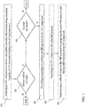
- FIG. 1 shows a flow diagram illustrating a process of analyzing a turbomachine component (e.g., a gas turbomachine component) according to various embodiments of the invention.
- a turbomachine component e.g., a gas turbomachine component
- One or more of these processes can be performed, e.g., by at least one computing device, as described herein. In other cases, one or more of these processes can be performed according to a computer-implemented method. In still other embodiments, one or more of these processes can be performed by executing computer program code on at least one computing device, causing the at least one computing device to perform a process, e.g., analyzing.
- the process can include the following sub-processes:
- the void status of the gas turbomachine component can be recorded, e.g., after a first HIP process, and that recorded void status can be used to determine an effectiveness of subsequent HIP processes on the component.
- This void status data can also be used to track deterioration of the gas turbomachine component over time and/or over repair intervals (e.g., HIP process intervals).
- Processes P1-P4 can be iterated (repeated) periodically (e.g., according to schedule of x times per y period, and/or continuously) in order to monitor one or more GT components. In some cases, processes P1-P4 can be repeated, for example, for a set of GT components.
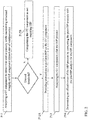
- FIG. 2 shows a flow diagram illustrating a process of analyzing a turbomachine component (e.g., a GT component) according to various embodiments of the invention.
- a turbomachine component e.g., a GT component
- One or more of these processes can be performed, e.g., by at least one computing device, as described herein. In other cases, one or more of these processes can be performed according to a computer-implemented method. In still other embodiments, one or more of these processes can be performed by executing computer program code on at least one computing device, causing the at least one computing device to perform a process, e.g., analyzing.
- the process can include the following sub-processes:
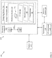
- FIG. 3 shows an illustrative environment 101 including a monitoring system 114, for performing the functions described herein according to various embodiments of the invention.
- the environment 101 includes a computer system 102 that can perform one or more processes described herein in order to monitor a GT component 117, e.g., from a turbomachine 118.
- the computer system 102 is shown as including the monitoring system 114, which makes computer system 102 operable to monitor a GT component 117 by performing any/all of the processes described herein and implementing any/all of the embodiments described herein.
- the computer system 102 is shown including a computing device 124, which can include a processing component 104 (e.g., one or more processors, or processing units (PUs) 111), a storage component 106 (e.g., a storage hierarchy), an input/output (I/O) component 108 (e.g., one or more I/O interfaces and/or devices), and a communications pathway 110.
- the processing component 104 executes program code, such as the monitoring system 114, which is at least partially fixed in the storage component 106. While executing program code, the processing component 104 can process data, which can result in reading and/or writing transformed data from/to the storage component 106 and/or the I/O component 108 for further processing.
- the pathway 110 provides a communications link between each of the components in the computer system 102.
- the I/O component 108 can comprise one or more human I/O devices, which enable a user (e.g., a human and/or computerized user) 112 to interact with the computer system 102 and/or one or more communications devices to enable the system user 112 to communicate with the computer system 102 using any type of communications link.
- the monitoring system 114 can manage a set of interfaces (e.g., graphical user interface(s), application program interface, etc.) that enable human and/or system users 112 to interact with the monitoring system 114.
- the monitoring system 114 can manage (e.g., store, retrieve, create, manipulate, organize, present, etc.) data, such as computed tomography (CT) data 60 (e.g., data about the presence or absence of voids in the GT component 117, size of voids in the GT component 117, creep measurement data about the GT component 117, etc., obtained by detection system 150), microfocus data 80 (data about the presence or absence of voids in the GT component 117, size of voids in the GT component 117, creep measurement data about the GT component 117, etc., obtained by detection system 150) and/or threshold data 90 (e.g., data about one or more thresholds, e.g., repair criteria threshold(s), void threshold(s), creep threshold(s), etc.) using any solution.
- the monitoring system 114 can additionally communicate with a turbomachine 118 and/or the detection system 150 (e.g., a CT system and/or microfocus system) via wireless and/or hardwired means.
- the computer system 102 can comprise one or more general purpose computing articles of manufacture (e.g., computing devices) capable of executing program code, such as the monitoring system 114, installed thereon.
- program code means any collection of instructions, in any language, code or notation, that cause a computing device having an information processing capability to perform a particular function either directly or after any combination of the following: (a) conversion to another language, code or notation; (b) reproduction in a different material form; and/or (c) decompression.
- the monitoring system 114 can be embodied as any combination of system software and/or application software.
- monitoring system 114 can be implemented in a cloud-based computing environment, where one or more processes are performed at distinct computing devices (e.g., a plurality of computing devices 124), where one or more of those distinct computing devices may contain only some of the components shown and described with respect to the computing device 124 of FIG. 3 .
- the monitoring system 114 can be implemented using a set of modules 132.
- a module 132 can enable the computer system 102 to perform a set of tasks used by the monitoring system 114, and can be separately developed and/or implemented apart from other portions of the monitoring system 114.
- the term "component” means any configuration of hardware, with or without software, which implements the functionality described in conjunction therewith using any solution, while the term “module” means program code that enables the computer system 102 to implement the functionality described in conjunction therewith using any solution.
- a module is a substantial portion of a component that implements the functionality.
- each computing device may have only a portion of monitoring system 114 fixed thereon (e.g., one or more modules 132).
- monitoring system 114 are only representative of various possible equivalent computer systems that may perform a process described herein.
- the functionality provided by the computer system 102 and monitoring system 114 can be at least partially implemented by one or more computing devices that include any combination of general and/or specific purpose hardware with or without program code.
- the hardware and program code, if included, can be created using standard engineering and programming techniques, respectively.
- the computing devices can communicate over any type of communications link. Further, while performing a process described herein, the computer system 102 can communicate with one or more other computer systems using any type of communications link. In either case, the communications link can comprise any combination of various types of wired and/or wireless links; comprise any combination of one or more types of networks; and/or utilize any combination of various types of transmission techniques and protocols.
- the computer system 102 can obtain or provide data, such as CT data 60, microfocus data 80 and/or threshold data 90 using any solution.
- the computer system 102 can generate CT data 60, microfocus data 80 and/or threshold data 90, from one or more data stores, receive CT data 60, microfocus data 80 and/or threshold data 90, from another system such as the turbomachine 118, detection system 150 and/or the user 112, send CT data 60, microfocus data 80 and/or threshold data 90 to another system, etc.
- the invention provides a computer program fixed in at least one computer-readable medium, which when executed, enables a computer system to monitor a GT component 117.
- the computer-readable medium includes program code, such as the monitoring system 114 ( FIG. 3 ), which implements some or all of the processes and/or embodiments described herein.
- the term "computer-readable medium" comprises one or more of any type of tangible medium of expression, now known or later developed, from which a copy of the program code can be perceived, reproduced, or otherwise communicated by a computing device.
- the computer-readable medium can comprise: one or more portable storage articles of manufacture; one or more memory/storage components of a computing device; paper; etc.
- the invention provides a method of providing a copy of program code, such as the monitoring system 114 ( FIG. 3 ), which implements some or all of a process described herein.
- a computer system can process a copy of program code that implements some or all of a process described herein to generate and transmit, for reception at a second, distinct location, a set of data signals that has one or more of its characteristics set and/or changed in such a manner as to encode a copy of the program code in the set of data signals.
- an embodiment of the invention provides a method of acquiring a copy of program code that implements some or all of a process described herein, which includes a computer system receiving the set of data signals described herein, and translating the set of data signals into a copy of the computer program fixed in at least one computer-readable medium.
- the set of data signals can be transmitted/received using any type of communications link.
- the invention provides a method of monitoring a lubrication oil
- a computer system such as the computer system 102 ( FIG. 3 ) can be obtained (e.g., created, maintained, made available, etc.) and one or more components for performing a process described herein can be obtained (e.g., created, purchased, used, modified, etc.) and deployed to the computer system.
- the deployment can comprise one or more of: (1) installing program code on a computing device; (2) adding one or more computing and/or I/O devices to the computer system; (3) incorporating and/or modifying the computer system to enable it to perform a process described herein; etc.
- the technical effect of the various embodiments of the invention is to monitor a component in a turbomachine 118 (e.g., a GT component 117).
- components described as being “coupled” to one another can be joined along one or more interfaces.
- these interfaces can include junctions between distinct components, and in other cases, these interfaces can include a solidly and/or integrally formed interconnection. That is, in some cases, components that are "coupled” to one another can be simultaneously formed to define a single continuous member.
- these coupled components can be formed as separate members and be subsequently joined through known processes (e.g., fastening, ultrasonic welding, bonding).
Claims (10)
- Verfahren, umfassend:Analysieren eines Gasturbinenbauteils (117), um mindestens eines von einem Hohlraum oder einer Porosität des Gasturbinenbauteils (117) zu erkennen, während eine strukturelle Integrität des Gasturbinenbauteils (117) beim Analysieren (P1) erhalten bleibt, wobei das Analysieren das Durchführen einer Computertomographie-Abtastung (CT-Abtastung) des Gasturbinenbauteils (117) und Mikrofokus-Analyse des Gasturbinenbauteils (117) einschließt;Bereitstellen von Anweisungen zum Durchführen eines heißisostatischen Pressprozesses (HIP) an dem Gasturbinenbauteil (117) als Antwort auf mindestens eines von dem Erkennen des Hohlraums oder dem Erkennen, dass die Porosität einen Schwellwert überschreitet (P2);Analysieren des Gasturbinenbauteils (117) nach dem HIP-Prozess (P3) undBestimmen einer Effektivität des HIP-Prozesses durch Vergleichen der Analyse des Gasturbinenbauteils (117), um mindestens eines von einem Hohlraum oder einer Porosität zu erkennen, mit der Analyse des Gasturbinenbauteils (117) nach dem HIP-Prozess (P4).
- Verfahren nach Anspruch 1, wobei das Gasturbinenbauteil (117) ein kriechbegrenztes Bauteil zur Verwendung in einer Gasturbomaschine (118) einschließt.
- Verfahren nach Anspruch 2, wobei das kriechbegrenzte Bauteil mindestens eines von einer Düse oder einer Schaufel einschließt.
- Verfahren nach einem der vorstehenden Ansprüche, wobei das Analysieren an einem gleichen physischen Ort durchgeführt wird, an dem sich eine Gasturbomaschine (118) zum Aufnehmen des Gasturbinenbauteils (117) befindet.
- Verfahren nach Anspruch 4, wobei das Analysieren in situ innerhalb der Gasturbomaschine (118) durchgeführt wird.
- Verfahren nach einem der vorstehenden Ansprüche, wobei der Hohlraum eine Dimensionsänderung in dem Gasturbinenbauteil (117) im Vergleich mit einem vorher festgelegten Dimensionswert des Gasturbinenbauteils (117) einschließt, und wobei das Analysieren das Bestimmen einer Größe des Hohlraums einschließt.
- Verfahren nach einem der vorstehenden Ansprüche, ferner umfassend:Vergleichen der Analyse des Gasturbinenbauteils (117) mit einem Schwellenwert für Reparaturkriterien für das Gasturbinenbauteil (117); undBereitstellen von Anweisungen zum Durchführen eines heißisostatischen Pressprozesses (HIP) an dem Gasturbinenbauteil (117) als Antwort auf das Bestimmen, dass die Analyse des Gasturbinenbauteils einen Schwellenwert für Reparaturkriterien überschreitet.
- Verfahren nach Anspruch 7, wobei das Analysieren, um mindestens eines von dem Hohlraum oder der Porosität zu erkennen, das Erkennen einer Größe von mindestens einem von dem Hohlraum oder der Porosität einschließt.
- Verfahren nach Anspruch 7, wobei der Schwellenwert für Reparaturkriterien auf der Größe von dem mindestens einen von dem Hohlraum oder der Porosität basiert.
- Verfahren nach Anspruch 7, wobei der Schwellenwert für Reparaturkriterien auf dem Vorhandensein von mindestens einem Kriech-Hohlraum oder mindestens einem inneren Riss in dem Gasturbinenbauteil basiert.
Priority Applications (1)
| Application Number | Priority Date | Filing Date | Title |
|---|---|---|---|
| PL14190940T PL2873966T3 (pl) | 2013-10-30 | 2014-10-29 | Monitorowanie komponentu turbiny gazowej |
Applications Claiming Priority (1)
| Application Number | Priority Date | Filing Date | Title |
|---|---|---|---|
| US14/067,136 US8991241B1 (en) | 2013-10-30 | 2013-10-30 | Gas turbine component monitoring |
Publications (2)
| Publication Number | Publication Date |
|---|---|
| EP2873966A1 EP2873966A1 (de) | 2015-05-20 |
| EP2873966B1 true EP2873966B1 (de) | 2020-07-29 |
Family
ID=51845306
Family Applications (1)
| Application Number | Title | Priority Date | Filing Date |
|---|---|---|---|
| EP14190940.8A Active EP2873966B1 (de) | 2013-10-30 | 2014-10-29 | Gasturbinenbauteilüberwachung |
Country Status (6)
| Country | Link |
|---|---|
| US (1) | US8991241B1 (de) |
| EP (1) | EP2873966B1 (de) |
| JP (1) | JP2015092157A (de) |
| CN (1) | CN104596743A (de) |
| HU (1) | HUE051408T2 (de) |
| PL (1) | PL2873966T3 (de) |
Families Citing this family (3)
| Publication number | Priority date | Publication date | Assignee | Title |
|---|---|---|---|---|
| WO2015073852A1 (en) * | 2013-11-15 | 2015-05-21 | United Technologies Corporation | Component with embedded sensor |
| KR102415574B1 (ko) * | 2020-10-27 | 2022-07-05 | 한국전력공사 | 가스터빈 블레이드의 내부 유동장 분석 방법 |
| US20220136405A1 (en) * | 2020-10-29 | 2022-05-05 | General Electric Company | Systems and methods of servicing equipment |
Family Cites Families (21)
| Publication number | Priority date | Publication date | Assignee | Title |
|---|---|---|---|---|
| US4302256A (en) * | 1979-11-16 | 1981-11-24 | Chromalloy American Corporation | Method of improving mechanical properties of alloy parts |
| US4567769A (en) * | 1984-03-08 | 1986-02-04 | Rockwell International Corporation | Contact-free ultrasonic transduction for flaw and acoustic discontinuity detection |
| JP2002256887A (ja) * | 2001-03-01 | 2002-09-11 | Toshiba Corp | ガスタービン部品の表面劣化抑制方法および本方法を使用したガスタービン部品 |
| JP2003014705A (ja) | 2001-06-27 | 2003-01-15 | Mitsubishi Heavy Ind Ltd | 金属材料の損傷評価方法 |
| JP3825378B2 (ja) | 2002-08-27 | 2006-09-27 | 三菱重工業株式会社 | 耐熱鋼の寿命評価方法 |
| JP3803314B2 (ja) | 2002-10-23 | 2006-08-02 | 財団法人発電設備技術検査協会 | クリープボイドの非破壊検出方法 |
| JP2004212366A (ja) | 2003-01-09 | 2004-07-29 | Mitsubishi Heavy Ind Ltd | クリープ損傷検出方法 |
| JP2005030846A (ja) | 2003-07-10 | 2005-02-03 | Sumitomo Chem Co Ltd | クリープボイドの検出方法 |
| US7174788B2 (en) * | 2003-12-15 | 2007-02-13 | General Electric Company | Methods and apparatus for rotary machinery inspection |
| US20050139581A1 (en) * | 2003-12-24 | 2005-06-30 | Yiping Hu | High-strength superalloy joining method for repairing turbine blades |
| US6905728B1 (en) * | 2004-03-22 | 2005-06-14 | Honeywell International, Inc. | Cold gas-dynamic spray repair on gas turbine engine components |
| DE102008021639A1 (de) * | 2008-04-30 | 2009-12-03 | Fraunhofer-Gesellschaft zur Förderung der angewandten Forschung e.V. | Vorrichtung und Verfahren zum Erzeugen einer CT-Rekonstruktion eines Objekts mit einem hochaufgelösten interessierenden Objektbereich |
| US20090316853A1 (en) * | 2008-06-24 | 2009-12-24 | Parazzoli Claudio G | Brilliant x-rays for casting inspection radiography and computed tomography |
| CN101435784B (zh) * | 2008-10-14 | 2012-01-18 | 重庆大学 | 涡轮叶片ct检测装置及其检测方法 |
| US20100263450A1 (en) * | 2009-04-16 | 2010-10-21 | Bobrek Richard S | System and method for producing and testing metal parts |
| US8442301B2 (en) * | 2009-04-30 | 2013-05-14 | General Electric Company | Nondestructive inspection method and system |
| FR2953747B1 (fr) * | 2009-12-14 | 2012-03-23 | Snecma | Procede de reparation d'une aube en titane par rechargement laser et compression hip moderee |
| CN102869973B (zh) * | 2010-04-23 | 2016-01-20 | 西门子公司 | 用于检查涡轮叶片的检验系统 |
| GB201105926D0 (en) * | 2011-04-08 | 2011-05-18 | Rolls Royce Plc | An apparatus and a method of determining the proportions of different powders in a powder |
| US8413493B1 (en) * | 2011-12-12 | 2013-04-09 | Florida Turbine Technologies, Inc. | Method for detecting a defect on an operating turbine rotor blade |
| CN102967693B (zh) * | 2012-11-12 | 2014-10-08 | 西安航空动力股份有限公司 | 钛合金铸件加工中的渗透检测与缺陷修复方法 |
-
2013
- 2013-10-30 US US14/067,136 patent/US8991241B1/en active Active
-
2014
- 2014-10-27 JP JP2014217905A patent/JP2015092157A/ja active Pending
- 2014-10-29 HU HUE14190940A patent/HUE051408T2/hu unknown
- 2014-10-29 PL PL14190940T patent/PL2873966T3/pl unknown
- 2014-10-29 EP EP14190940.8A patent/EP2873966B1/de active Active
- 2014-10-30 CN CN201410596725.1A patent/CN104596743A/zh active Pending
Non-Patent Citations (1)
| Title |
|---|
| None * |
Also Published As
| Publication number | Publication date |
|---|---|
| US8991241B1 (en) | 2015-03-31 |
| CN104596743A (zh) | 2015-05-06 |
| PL2873966T3 (pl) | 2021-01-11 |
| JP2015092157A (ja) | 2015-05-14 |
| HUE051408T2 (hu) | 2021-03-01 |
| EP2873966A1 (de) | 2015-05-20 |
Similar Documents
| Publication | Publication Date | Title |
|---|---|---|
| Ayo-Imoru et al. | A survey of the state of condition-based maintenance (CBM) in the nuclear power industry | |
| KR101677015B1 (ko) | Eifs 불확실성을 고려하여 초음파 검사 데이터를 사용한 확률적 피로 수명 예측 | |
| JP2016509670A (ja) | 疲労損傷予知および構造健全性評価のための非破壊検査における内部欠陥の確率論的モデリングおよびサイジング | |
| EP2873966B1 (de) | Gasturbinenbauteilüberwachung | |
| Bond et al. | Prognostics and life beyond 60 years for nuclear power plants | |
| Guan et al. | Probabilistic modeling and sizing of embedded flaws in ultrasonic non-destructive inspections for fatigue damage prognostics and structural integrity assessment | |
| EP2530460B1 (de) | Herstellung von Testkomponenten mit künstlichen Defekten zur Analyse von Produktionskomponenten | |
| US20040240600A1 (en) | Positron annihilation for inspection of land based industrial gas turbine components | |
| Barrett et al. | Virtual engineering of a fusion reactor: application to divertor design, manufacture, and testing | |
| JP2018021908A (ja) | 埋め込み型歪みセンサネットワーク | |
| Ganjdoust et al. | A novel delamination damage detection strategy based on inverse finite element method for structural health monitoring of composite structures | |
| WO2019163979A1 (ja) | 保守管理メニュー決定方法及びプラントの保守管理方法 | |
| Woo et al. | Integrity analysis of dented pipelines using artificial neural networks | |
| Bond | From nondestructive testing to prognostics: Revisited | |
| Roh et al. | A hierarchical V-network framework for part qualification in metal additive manufacturing | |
| Witherell | Digital Twins for Part Acceptance in Advanced Manufacturing Applications with Regulatory Considerations | |
| Trampus | Ensuring safety of structures and components at nuclear power plants | |
| Dutton et al. | Non-Destructive Evaluation for Additive Manufacturing | |
| Gerards-Wünsche et al. | A framework for assessing the reliability of crack luminescence: an automated fatigue crack detection system | |
| Ellis et al. | Diagnosis and Prognosis of Mechanical Components Using Hybrid Methods | |
| Guan et al. | Turbine fatigue reliability and life assessment using ultrasonic inspection: Data acquisition, interpretation, and probabilistic modeling | |
| Abbasi et al. | NDE and material evaluation for lifetime assessment of power plant components | |
| Keprate et al. | Inspection planning and maintenance scheduling of offshore piping undergoing fatigue degradation: A probabilistic view | |
| Dedekind et al. | Evaluation of premature failure of a gas turbine component | |
| Lockey et al. | Modelling shallow dents using local regression methods and finite element analysis |
Legal Events
| Date | Code | Title | Description |
|---|---|---|---|
| PUAI | Public reference made under article 153(3) epc to a published international application that has entered the european phase |
Free format text: ORIGINAL CODE: 0009012 |
|
| 17P | Request for examination filed |
Effective date: 20141029 |
|
| AK | Designated contracting states |
Kind code of ref document: A1 Designated state(s): AL AT BE BG CH CY CZ DE DK EE ES FI FR GB GR HR HU IE IS IT LI LT LU LV MC MK MT NL NO PL PT RO RS SE SI SK SM TR |
|
| AX | Request for extension of the european patent |
Extension state: BA ME |
|
| R17P | Request for examination filed (corrected) |
Effective date: 20151120 |
|
| RBV | Designated contracting states (corrected) |
Designated state(s): AL AT BE BG CH CY CZ DE DK EE ES FI FR GB GR HR HU IE IS IT LI LT LU LV MC MK MT NL NO PL PT RO RS SE SI SK SM TR |
|
| RIC1 | Information provided on ipc code assigned before grant |
Ipc: G01M 15/14 20060101ALI20200113BHEP Ipc: G01N 23/04 20180101AFI20200113BHEP |
|
| GRAP | Despatch of communication of intention to grant a patent |
Free format text: ORIGINAL CODE: EPIDOSNIGR1 |
|
| STAA | Information on the status of an ep patent application or granted ep patent |
Free format text: STATUS: GRANT OF PATENT IS INTENDED |
|
| INTG | Intention to grant announced |
Effective date: 20200227 |
|
| GRAS | Grant fee paid |
Free format text: ORIGINAL CODE: EPIDOSNIGR3 |
|
| GRAA | (expected) grant |
Free format text: ORIGINAL CODE: 0009210 |
|
| STAA | Information on the status of an ep patent application or granted ep patent |
Free format text: STATUS: THE PATENT HAS BEEN GRANTED |
|
| AK | Designated contracting states |
Kind code of ref document: B1 Designated state(s): AL AT BE BG CH CY CZ DE DK EE ES FI FR GB GR HR HU IE IS IT LI LT LU LV MC MK MT NL NO PL PT RO RS SE SI SK SM TR |
|
| REG | Reference to a national code |
Ref country code: CH Ref legal event code: EP |
|
| REG | Reference to a national code |
Ref country code: AT Ref legal event code: REF Ref document number: 1296369 Country of ref document: AT Kind code of ref document: T Effective date: 20200815 |
|
| REG | Reference to a national code |
Ref country code: IE Ref legal event code: FG4D |
|
| REG | Reference to a national code |
Ref country code: DE Ref legal event code: R096 Ref document number: 602014068224 Country of ref document: DE |
|
| REG | Reference to a national code |
Ref country code: LT Ref legal event code: MG4D |
|
| REG | Reference to a national code |
Ref country code: NL Ref legal event code: MP Effective date: 20200729 |
|
| REG | Reference to a national code |
Ref country code: AT Ref legal event code: MK05 Ref document number: 1296369 Country of ref document: AT Kind code of ref document: T Effective date: 20200729 |
|
| PG25 | Lapsed in a contracting state [announced via postgrant information from national office to epo] |
Ref country code: BG Free format text: LAPSE BECAUSE OF FAILURE TO SUBMIT A TRANSLATION OF THE DESCRIPTION OR TO PAY THE FEE WITHIN THE PRESCRIBED TIME-LIMIT Effective date: 20201029 Ref country code: GR Free format text: LAPSE BECAUSE OF FAILURE TO SUBMIT A TRANSLATION OF THE DESCRIPTION OR TO PAY THE FEE WITHIN THE PRESCRIBED TIME-LIMIT Effective date: 20201030 Ref country code: ES Free format text: LAPSE BECAUSE OF FAILURE TO SUBMIT A TRANSLATION OF THE DESCRIPTION OR TO PAY THE FEE WITHIN THE PRESCRIBED TIME-LIMIT Effective date: 20200729 Ref country code: SE Free format text: LAPSE BECAUSE OF FAILURE TO SUBMIT A TRANSLATION OF THE DESCRIPTION OR TO PAY THE FEE WITHIN THE PRESCRIBED TIME-LIMIT Effective date: 20200729 Ref country code: PT Free format text: LAPSE BECAUSE OF FAILURE TO SUBMIT A TRANSLATION OF THE DESCRIPTION OR TO PAY THE FEE WITHIN THE PRESCRIBED TIME-LIMIT Effective date: 20201130 Ref country code: FI Free format text: LAPSE BECAUSE OF FAILURE TO SUBMIT A TRANSLATION OF THE DESCRIPTION OR TO PAY THE FEE WITHIN THE PRESCRIBED TIME-LIMIT Effective date: 20200729 Ref country code: NO Free format text: LAPSE BECAUSE OF FAILURE TO SUBMIT A TRANSLATION OF THE DESCRIPTION OR TO PAY THE FEE WITHIN THE PRESCRIBED TIME-LIMIT Effective date: 20201029 Ref country code: HR Free format text: LAPSE BECAUSE OF FAILURE TO SUBMIT A TRANSLATION OF THE DESCRIPTION OR TO PAY THE FEE WITHIN THE PRESCRIBED TIME-LIMIT Effective date: 20200729 Ref country code: AT Free format text: LAPSE BECAUSE OF FAILURE TO SUBMIT A TRANSLATION OF THE DESCRIPTION OR TO PAY THE FEE WITHIN THE PRESCRIBED TIME-LIMIT Effective date: 20200729 Ref country code: LT Free format text: LAPSE BECAUSE OF FAILURE TO SUBMIT A TRANSLATION OF THE DESCRIPTION OR TO PAY THE FEE WITHIN THE PRESCRIBED TIME-LIMIT Effective date: 20200729 |
|
| PG25 | Lapsed in a contracting state [announced via postgrant information from national office to epo] |
Ref country code: IS Free format text: LAPSE BECAUSE OF FAILURE TO SUBMIT A TRANSLATION OF THE DESCRIPTION OR TO PAY THE FEE WITHIN THE PRESCRIBED TIME-LIMIT Effective date: 20201129 Ref country code: RS Free format text: LAPSE BECAUSE OF FAILURE TO SUBMIT A TRANSLATION OF THE DESCRIPTION OR TO PAY THE FEE WITHIN THE PRESCRIBED TIME-LIMIT Effective date: 20200729 Ref country code: LV Free format text: LAPSE BECAUSE OF FAILURE TO SUBMIT A TRANSLATION OF THE DESCRIPTION OR TO PAY THE FEE WITHIN THE PRESCRIBED TIME-LIMIT Effective date: 20200729 |
|
| REG | Reference to a national code |
Ref country code: HU Ref legal event code: AG4A Ref document number: E051408 Country of ref document: HU |
|
| PG25 | Lapsed in a contracting state [announced via postgrant information from national office to epo] |
Ref country code: NL Free format text: LAPSE BECAUSE OF FAILURE TO SUBMIT A TRANSLATION OF THE DESCRIPTION OR TO PAY THE FEE WITHIN THE PRESCRIBED TIME-LIMIT Effective date: 20200729 |
|
| PG25 | Lapsed in a contracting state [announced via postgrant information from national office to epo] |
Ref country code: SM Free format text: LAPSE BECAUSE OF FAILURE TO SUBMIT A TRANSLATION OF THE DESCRIPTION OR TO PAY THE FEE WITHIN THE PRESCRIBED TIME-LIMIT Effective date: 20200729 Ref country code: RO Free format text: LAPSE BECAUSE OF FAILURE TO SUBMIT A TRANSLATION OF THE DESCRIPTION OR TO PAY THE FEE WITHIN THE PRESCRIBED TIME-LIMIT Effective date: 20200729 Ref country code: EE Free format text: LAPSE BECAUSE OF FAILURE TO SUBMIT A TRANSLATION OF THE DESCRIPTION OR TO PAY THE FEE WITHIN THE PRESCRIBED TIME-LIMIT Effective date: 20200729 Ref country code: CZ Free format text: LAPSE BECAUSE OF FAILURE TO SUBMIT A TRANSLATION OF THE DESCRIPTION OR TO PAY THE FEE WITHIN THE PRESCRIBED TIME-LIMIT Effective date: 20200729 Ref country code: DK Free format text: LAPSE BECAUSE OF FAILURE TO SUBMIT A TRANSLATION OF THE DESCRIPTION OR TO PAY THE FEE WITHIN THE PRESCRIBED TIME-LIMIT Effective date: 20200729 |
|
| REG | Reference to a national code |
Ref country code: DE Ref legal event code: R097 Ref document number: 602014068224 Country of ref document: DE |
|
| PG25 | Lapsed in a contracting state [announced via postgrant information from national office to epo] |
Ref country code: AL Free format text: LAPSE BECAUSE OF FAILURE TO SUBMIT A TRANSLATION OF THE DESCRIPTION OR TO PAY THE FEE WITHIN THE PRESCRIBED TIME-LIMIT Effective date: 20200729 |
|
| REG | Reference to a national code |
Ref country code: CH Ref legal event code: PL |
|
| PLBE | No opposition filed within time limit |
Free format text: ORIGINAL CODE: 0009261 |
|
| STAA | Information on the status of an ep patent application or granted ep patent |
Free format text: STATUS: NO OPPOSITION FILED WITHIN TIME LIMIT |
|
| PG25 | Lapsed in a contracting state [announced via postgrant information from national office to epo] |
Ref country code: SK Free format text: LAPSE BECAUSE OF FAILURE TO SUBMIT A TRANSLATION OF THE DESCRIPTION OR TO PAY THE FEE WITHIN THE PRESCRIBED TIME-LIMIT Effective date: 20200729 Ref country code: LU Free format text: LAPSE BECAUSE OF NON-PAYMENT OF DUE FEES Effective date: 20201029 Ref country code: MC Free format text: LAPSE BECAUSE OF FAILURE TO SUBMIT A TRANSLATION OF THE DESCRIPTION OR TO PAY THE FEE WITHIN THE PRESCRIBED TIME-LIMIT Effective date: 20200729 |
|
| 26N | No opposition filed |
Effective date: 20210430 |
|
| REG | Reference to a national code |
Ref country code: BE Ref legal event code: MM Effective date: 20201031 |
|
| PG25 | Lapsed in a contracting state [announced via postgrant information from national office to epo] |
Ref country code: SI Free format text: LAPSE BECAUSE OF FAILURE TO SUBMIT A TRANSLATION OF THE DESCRIPTION OR TO PAY THE FEE WITHIN THE PRESCRIBED TIME-LIMIT Effective date: 20200729 Ref country code: LI Free format text: LAPSE BECAUSE OF NON-PAYMENT OF DUE FEES Effective date: 20201031 Ref country code: CH Free format text: LAPSE BECAUSE OF NON-PAYMENT OF DUE FEES Effective date: 20201031 Ref country code: BE Free format text: LAPSE BECAUSE OF NON-PAYMENT OF DUE FEES Effective date: 20201031 |
|
| PG25 | Lapsed in a contracting state [announced via postgrant information from national office to epo] |
Ref country code: IE Free format text: LAPSE BECAUSE OF NON-PAYMENT OF DUE FEES Effective date: 20201029 |
|
| PG25 | Lapsed in a contracting state [announced via postgrant information from national office to epo] |
Ref country code: MT Free format text: LAPSE BECAUSE OF FAILURE TO SUBMIT A TRANSLATION OF THE DESCRIPTION OR TO PAY THE FEE WITHIN THE PRESCRIBED TIME-LIMIT Effective date: 20200729 Ref country code: CY Free format text: LAPSE BECAUSE OF FAILURE TO SUBMIT A TRANSLATION OF THE DESCRIPTION OR TO PAY THE FEE WITHIN THE PRESCRIBED TIME-LIMIT Effective date: 20200729 |
|
| PG25 | Lapsed in a contracting state [announced via postgrant information from national office to epo] |
Ref country code: MK Free format text: LAPSE BECAUSE OF FAILURE TO SUBMIT A TRANSLATION OF THE DESCRIPTION OR TO PAY THE FEE WITHIN THE PRESCRIBED TIME-LIMIT Effective date: 20200729 |
|
| PGFP | Annual fee paid to national office [announced via postgrant information from national office to epo] |
Ref country code: IT Payment date: 20230920 Year of fee payment: 10 Ref country code: GB Payment date: 20230920 Year of fee payment: 10 |
|
| REG | Reference to a national code |
Ref country code: DE Ref legal event code: R081 Ref document number: 602014068224 Country of ref document: DE Owner name: GENERAL ELECTRIC TECHNOLOGY GMBH, CH Free format text: FORMER OWNER: GENERAL ELECTRIC COMPANY, SCHENECTADY, NY, US |
|
| PGFP | Annual fee paid to national office [announced via postgrant information from national office to epo] |
Ref country code: PL Payment date: 20230921 Year of fee payment: 10 Ref country code: FR Payment date: 20230920 Year of fee payment: 10 |
|
| REG | Reference to a national code |
Ref country code: HU Ref legal event code: GB9C Owner name: GENERAL ELECTRIC TECHNOLOGY GMBH, CH Free format text: FORMER OWNER(S): GENERAL ELECTRIC COMPANY, US |
|
| PGFP | Annual fee paid to national office [announced via postgrant information from national office to epo] |
Ref country code: TR Payment date: 20231002 Year of fee payment: 10 Ref country code: HU Payment date: 20231004 Year of fee payment: 10 Ref country code: DE Payment date: 20230920 Year of fee payment: 10 |
|
| REG | Reference to a national code |
Ref country code: GB Ref legal event code: 732E Free format text: REGISTERED BETWEEN 20240222 AND 20240228 |