EP2873597B1 - Vorrichtung zur Befestigung einer Umlaufstrebe am Rahmen eines Zweirades sowie Anordnung der Umlaufstrebe an dem Rahmen des Zweirades - Google Patents
Vorrichtung zur Befestigung einer Umlaufstrebe am Rahmen eines Zweirades sowie Anordnung der Umlaufstrebe an dem Rahmen des Zweirades Download PDFInfo
- Publication number
- EP2873597B1 EP2873597B1 EP13192853.3A EP13192853A EP2873597B1 EP 2873597 B1 EP2873597 B1 EP 2873597B1 EP 13192853 A EP13192853 A EP 13192853A EP 2873597 B1 EP2873597 B1 EP 2873597B1
- Authority
- EP
- European Patent Office
- Prior art keywords
- bicycle
- mount
- section
- mudguard
- stay
- Prior art date
- Legal status (The legal status is an assumption and is not a legal conclusion. Google has not performed a legal analysis and makes no representation as to the accuracy of the status listed.)
- Active
Links
Images


Classifications
-
- B—PERFORMING OPERATIONS; TRANSPORTING
- B62—LAND VEHICLES FOR TRAVELLING OTHERWISE THAN ON RAILS
- B62J—CYCLE SADDLES OR SEATS; AUXILIARY DEVICES OR ACCESSORIES SPECIALLY ADAPTED TO CYCLES AND NOT OTHERWISE PROVIDED FOR, e.g. ARTICLE CARRIERS OR CYCLE PROTECTORS
- B62J15/00—Mud-guards for wheels
- B62J15/02—Fastening means; Stays
Definitions
- the present invention relates to a device for fastening a trained as a circumferential strut strut on the frame of a bicycle according to the preamble of claim 1 and an arrangement of serving for supporting a wheel guard circulating strut on the frame of a bicycle according to the preamble of claim 14.
- a strut With a strut in the present application, a strut will be referred to, which has a substantially U-shaped configuration with a first portion, a second portion and a cross section connecting them.
- the ends of the two sections facing away from the transverse section on different sides of the wheel of the two-wheeled vehicle are connected to the two-wheeler, in particular the fork of the two-wheeler.
- the Radstener is connected to the transverse section of the revolving strut.
- a revolving strut therefore differs significantly from a conventional V-shaped strut.
- the ends of the two V-legs are connected on the same side of the wheel with the Radverseer, whereas the connecting portion of the two V-legs is connected to the fork of the bicycle in the region of the hub.
- at least two V-shaped struts are required for the attachment of the wheel guard, which are arranged on opposite sides of the wheel.
- a device for fixing a not designed as a revolving strut V-shaped strut on the frame of a two-wheeler is from the European patent application EP 0 803 429 A2 known.
- a first part as a connection part formed with a receptacle and a second part as a plug-in part with a plug-in portion in the receptacle, wherein by inserting this section into the receptacle, a releasable latching connection between the two parts is formed.
- the first part may be connected to the connecting region of the two V-legs of the strut and the second part to the frame of the bicycle in the region of the hub. To release the connection, the two parts must be pulled apart in the radial direction of the wheel.
- the releasable connection between the two parts is designed so that at forces exceeding a predetermined strength, the connection is released. Such forces can occur, for example, when an object between the spokes and pushed by the rotational movement of the wheel under the Radpetiter. In order to avoid an accident, the connection between the two parts releases and releases the wheel guards.
- the DE 203 00 726 U1 also discloses a device for securing a non-recirculating V-shaped Strut on the frame of a two-wheeler.
- the device comprises a strut connected to the first part having a receptacle with an opening.
- the device further comprises a second part connected to the frame, which has an engaging portion projecting into the opening, wherein a releasable latching connection between the two parts is formed by inserting this engaging portion into the receptacle.
- the engagement portion is part-cylindrical shaped, whereas the opening is partially hollow cylindrical shaped. The opening leads in a radial direction out of the receptacle, so that for releasing the connection, the two parts have to be pulled apart in the radial direction of the wheel.
- a device of the type mentioned is from the EP 0 989 055 A2 , wherein a device for fastening two struts is disclosed on the frame of a bicycle, in which the two struts either parallel to each other in the radial direction or extend away from each other at a small angle to the radial direction.
- the EP 0 989 055 A2 discloses on each side of the wheel one of these devices, wherein the Radverseer devisen ends of the struts arranged on different sides are connected to each other via a bridge enclosing the wheel guard.
- the device comprises a strut connected to the first part having a receptacle with an opening.
- the device further comprises a second part connected to the frame, which has an engaging portion projecting into the opening. The opening leads out of the receptacle in a radial direction and thus substantially in the direction in which the struts extend.
- the problem underlying the present invention is to provide a device of the type mentioned, the one Solution of the connection between the strut and the bicycle also guaranteed when using recirculating struts. Furthermore, an arrangement with such a device should be specified.
- the opening leads out in a direction of the receptacle, which is connected to the longitudinal extent of the portion of the revolving strut, which is connected in the mounted state with the first or the second part, an angle between 30 ° and 150 ° includes, so that the disengagement of the parts in the release of the compound in the two-wheel mounted state takes place in a direction which deviates from the radial direction of the wheel of the bicycle in the region of the circulation strut.
- the direction in which the movement apart of the parts takes place upon release of the connection with the radial direction of the wheel at an angle between 30 ° and 150 °, preferably an angle between 60 ° and 120 °, in particular one Angle between 75 ° and 105 °, for example, includes an angle of 90 °. Due to the solution taking place at an angle to the radial direction of the connection, the device according to the invention is also suitable for circulating struts.
- the opening can lead out of the receptacle in one direction, with the longitudinal extent of the portion of the revolving strut, the mounted in the two-wheeled state with the first or the second part, an angle between 60 ° and 120 °, in particular an angle between 75 ° and 105 °, for example, includes an angle of 90 °.
- the receptacle and the engagement portion may be formed so that the moving out of the engagement portion in the direction in which the opening leads out of the receptacle. In this way, the release of the two parts from each other can also take place when a force is exerted in the circumferential direction of the wheel on the circulation strut in the region of the Radverseers.
- the opening of the receptacle is arranged in the mounted state on the bicycle on the upper side of the first part. In this way, it is ensured that, in the case of a recirculating strut extending rearwardly from the hub of the wheel, the outward movement of the gripping section out of the opening can be upwards, so that movement of the circulating strut in the direction of movement of the wheel can cause the connection to be released.
- the receptacle has an undercut, wherein in particular the engagement portion is held in the connected state of the undercut of the receptacle in this.
- the receptacle has a hollow part-cylindrical area, wherein in particular the engagement portion has a part-cylindrical area which engages in the connected state in the hollow part-cylindrical portion of the receptacle.
- the receptacle and the engagement portion are formed so that the automatic solution of the connection starts with a one-sided moving out of the engagement portion of the receptacle.
- the receptacle and the engagement portion may be formed so that the moving out of the engagement portion at the end remote from the hub of the wheel begins and progresses in the longitudinal direction of the portion of the revolving strut. In this way, a solution of the compound can be ensured in a targeted manner in the circumferential direction acting on the circulating struts forces.
- one of the two parts comprises a receiving region for the portion of the revolving strut and fastening means, in particular screw means, for fixing the portion of the revolving strut. Furthermore, it can be provided that one of the two parts comprises fastening means, in particular screw means, for attachment to the bicycle.
- the arrangement comprises a device according to the invention.
- the arrangement comprises two devices according to the invention, which are respectively attached to the sections, in particular the end sections of the revolving strut. In this way can be done on both sides of the wheel at the same time a release of the compounds.
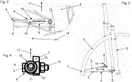
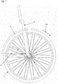
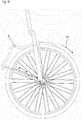
- the from the Fig. 1 to Fig. 3 apparent arrangement includes a front wheel 1 and a fork 2 of a bicycle. Furthermore, the arrangement comprises a Radsteer 3 and a circulating strut 4 for supporting the Radtenters 3.
- the Radtenter 3 may be made of metal, but preferably made of plastic.
- the Radtenter 3 is bent like a torus and adapted to the course of a bicycle tire.
- the circulating strut 4 has two sections 5, 6 extending substantially in the same direction (see FIG Fig. 3 ) and a cross section connecting them, which in Fig. 3 is covered by the Radtenter 3.
- the revolving strut 4 may be made of metal, for example, bent wire.
- the transverse section of the revolving strut 4 may be attached to the Radtenter.
- This device may be a device according to DE 10 2009 060 429 A1 be. However, it is quite possible to provide other facilities.
- the from the Fig. 1 to Fig. 3 apparent arrangement further comprises two devices 8 for securing the revolving strut 4 to the fork 2 of the bicycle.
- the device 8 comprises a first part 9, which is attached to the fork 2, and a second part 10, which with the in Fig. 3 front portion 6 of the revolving strut 4 is connected.
- the first part 9 has an upwardly open receptacle 11 in the mounted position, in which an engagement portion 12 of the second part 10 engages.
- Fig. 4 shows that the receptacle has an upper opening 13 has, through which the engagement portion 12 engages in the receptacle 11.
- the receptacle 11 has a hollow part-cylindrical cross-section and the engagement portion 12 has a matching part-cylindrical cross-section.
- Fig. 4 further shows that the hollow part cylinder of the receptacle 11 extends approximately over 270 °, thereby creating an undercut that holds the engagement portion 12 in the receptacle 11.
- Fig. 2 shows that the second part 10 includes screw means 14 which can set the inserted into a receiving portion of the second part 10 section 6 of the revolving strut 4 in the second part 10 (see also Fig. 4). 2 and FIG. 4 continue to show that the first part 9 includes screw means 15 which can fix the first part 9 on the fork 2.
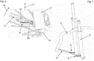
- the geometry of the wheel guard 3 can be seen that the rotational movement of the wheel 1 in the clockwise direction or in the direction of arrows 16 in the Fig. 1 . Fig. 5 . Fig. 6 and Fig. 8 he follows.
- the comparison of Fig. 2 with the Fig. 6 and Fig. 9 shows the release of the connection between the first and second part 9, 10 in the event of an unforeseen event, which leads for example to a deformation of the wheel guard 3 (see also the Fig. 7 and 10 ).
- Fig. 6 shows that the moving out of the engagement portion 12 from the receptacle 11, although substantially upward, but that the movement on the radially outer or respectively remote from the hub 19 of the wheel 1 side of the device 8 begins.
- This is due in particular to the fact that the forces acting on the revolving strut 4 or its sections 5, 6 act essentially in the circumferential direction or in the direction of the arrow 16.
- the engaging portion 12 of the second part 10 from left to right in Fig. 6 rotated upward from the receptacle 11 of the first part 9, wherein a rotation takes place about an area provided with the reference numeral 20.
- FIGS. 9 and 10 then show the end position of this movement, in which the two parts 9, 10 are completely detached from each other.
- a first part provided with a receptacle can be connected or connected to the section 6 of the revolving strut 4 and that a second part provided with an engagement section can be connected to a part of the two-wheeler, in particular the fork 2.
Landscapes
- Engineering & Computer Science (AREA)
- Mechanical Engineering (AREA)
- Axle Suspensions And Sidecars For Cycles (AREA)
- Body Structure For Vehicles (AREA)
Priority Applications (6)
| Application Number | Priority Date | Filing Date | Title |
|---|---|---|---|
| EP13192853.3A EP2873597B1 (de) | 2013-11-14 | 2013-11-14 | Vorrichtung zur Befestigung einer Umlaufstrebe am Rahmen eines Zweirades sowie Anordnung der Umlaufstrebe an dem Rahmen des Zweirades |
| PL13192853T PL2873597T3 (pl) | 2013-11-14 | 2013-11-14 | Urządzenie do mocowania wspornika obwodowego do ramy dwukołowego pojazdu oraz układ wspornika obwodowego na ramie pojazdu kołowego |
| DK13192853.3T DK2873597T3 (da) | 2013-11-14 | 2013-11-14 | Indretning til at fastgøre en skærmstiver på rammen af en cykel og samling af skærmstiveren på rammen af en cykel |
| HUE13192853A HUE035421T2 (en) | 2013-11-14 | 2013-11-14 | A device for securing a fender to a bicycle frame and assembling a fender for a bicycle frame |
| NO13192853A NO2873597T3 (da) | 2013-11-14 | 2013-11-14 | |
| LTEP13192853.3T LT2873597T (lt) | 2013-11-14 | 2013-11-14 | Purvasaugio atramos tvirtinimo ant dviračio rėmo įtaisas ir purvasaugio atramos montavimas ant dviračio rėmo |
Applications Claiming Priority (1)
| Application Number | Priority Date | Filing Date | Title |
|---|---|---|---|
| EP13192853.3A EP2873597B1 (de) | 2013-11-14 | 2013-11-14 | Vorrichtung zur Befestigung einer Umlaufstrebe am Rahmen eines Zweirades sowie Anordnung der Umlaufstrebe an dem Rahmen des Zweirades |
Publications (2)
| Publication Number | Publication Date |
|---|---|
| EP2873597A1 EP2873597A1 (de) | 2015-05-20 |
| EP2873597B1 true EP2873597B1 (de) | 2017-11-01 |
Family
ID=49582624
Family Applications (1)
| Application Number | Title | Priority Date | Filing Date |
|---|---|---|---|
| EP13192853.3A Active EP2873597B1 (de) | 2013-11-14 | 2013-11-14 | Vorrichtung zur Befestigung einer Umlaufstrebe am Rahmen eines Zweirades sowie Anordnung der Umlaufstrebe an dem Rahmen des Zweirades |
Country Status (6)
| Country | Link |
|---|---|
| EP (1) | EP2873597B1 (da) |
| DK (1) | DK2873597T3 (da) |
| HU (1) | HUE035421T2 (da) |
| LT (1) | LT2873597T (da) |
| NO (1) | NO2873597T3 (da) |
| PL (1) | PL2873597T3 (da) |
Family Cites Families (6)
| Publication number | Priority date | Publication date | Assignee | Title |
|---|---|---|---|---|
| JPS51109643A (en) * | 1975-03-24 | 1976-09-28 | Tsunoda Jitensha Kk | Jitenshaniokeru doroyokesuteenokoteisochi |
| DE29607628U1 (de) | 1996-04-26 | 1996-07-11 | SKS Metaplast Scheffer-Klute GmbH, 59846 Sundern | Einrichtung zur Befestigung von Streben eines Radschützers eines Fahrrads |
| GB9820590D0 (en) * | 1998-09-23 | 1998-11-11 | Webb Ronald R | Cycle mudguard stay release clip |
| DE20300726U1 (de) * | 2003-01-17 | 2003-03-20 | SKS Metaplast Scheffer-Klute GmbH, 59846 Sundern | Einrichtung zur Befestigung von Streben zur Halterung eines Radschützers am Rahmen eines Zweirades |
| ITVI20070323A1 (it) * | 2007-12-21 | 2009-06-22 | Ivan Passuello | Dispositivo di sgancio di sicurezza, particolarmente per asta di supporto e forcella. |
| DE102009060429B4 (de) | 2009-12-22 | 2014-03-20 | Sks Metaplast Scheffer-Klute Gmbh | Vorrichtung zur Befestigung einer Strebe an einem Radschützer eines Fahrrads sowie Anordnung der Strebe an dem Radschützer |
-
2013
- 2013-11-14 NO NO13192853A patent/NO2873597T3/no unknown
- 2013-11-14 HU HUE13192853A patent/HUE035421T2/en unknown
- 2013-11-14 DK DK13192853.3T patent/DK2873597T3/da active
- 2013-11-14 PL PL13192853T patent/PL2873597T3/pl unknown
- 2013-11-14 LT LTEP13192853.3T patent/LT2873597T/lt unknown
- 2013-11-14 EP EP13192853.3A patent/EP2873597B1/de active Active
Non-Patent Citations (1)
| Title |
|---|
| None * |
Also Published As
| Publication number | Publication date |
|---|---|
| NO2873597T3 (da) | 2018-03-31 |
| DK2873597T3 (da) | 2018-01-02 |
| PL2873597T3 (pl) | 2018-04-30 |
| HUE035421T2 (en) | 2018-05-02 |
| EP2873597A1 (de) | 2015-05-20 |
| LT2873597T (lt) | 2018-02-26 |
Similar Documents
| Publication | Publication Date | Title |
|---|---|---|
| EP1638822B1 (de) | Scheibenwischvorrichtung, insbesondere für ein kraftfahrzeug | |
| DE102018222834A1 (de) | Halterungselement und Fahrrad mit einem Halterungselement | |
| EP4393804A2 (de) | Fahrrad-schaltwerk und anbindung eines schaltwerks an einem fahrrad-rahmen | |
| DE102016110754A1 (de) | Befestigungsvorrichtung zum Befestigen eines ersten Bauteils an einem zweiten Bauteil | |
| EP2158120A1 (de) | Schaltauge mit einsetzhilfe | |
| DE202012008119U1 (de) | Lenkanschlag für Fahrradlenker | |
| DE102019108910A1 (de) | Mehrteiliges Verstellelement für eine Toleranzausgleichsanordnung | |
| DE3224589A1 (de) | Gepaecktraeger fuer ein zweirad | |
| EP3556647A1 (de) | Vorrichtung zur befestigung eines schaltwerks an einem fahrradrahmen | |
| WO2008101593A1 (de) | Schnellspannachse | |
| DE102018110525A1 (de) | Verfahren zur Montage einer Getriebekomponente einer Sitzhöhenverstellung | |
| DE102009060429B4 (de) | Vorrichtung zur Befestigung einer Strebe an einem Radschützer eines Fahrrads sowie Anordnung der Strebe an dem Radschützer | |
| EP1151911A2 (de) | Befestigungseinrichtung für einen Radschützer | |
| EP0694469A1 (de) | Schutzblechanordnung | |
| DE60106813T2 (de) | Fahrradbefestigungsstelle für motorgesteuerte Gangschaltung | |
| EP3178731B1 (de) | Radschützer für das vorderrad eines zweirades | |
| EP2881314B1 (de) | Fahrradgriff | |
| EP2873597B1 (de) | Vorrichtung zur Befestigung einer Umlaufstrebe am Rahmen eines Zweirades sowie Anordnung der Umlaufstrebe an dem Rahmen des Zweirades | |
| DE202017104339U1 (de) | Befestigung für das Anbauteil eines Fahrrads | |
| EP1439115B1 (de) | Einrichtung zur Befestigung von Streben zur Halterung eines Radschützers am Rahmen eines Zweirades | |
| EP3497002B1 (de) | Toleranzausgleichsrahmen für fuge um scheinwerfer | |
| EP2974947B1 (de) | Fahrradrahmenelement | |
| EP3546327B1 (de) | Gepäckträger für ein zweirad | |
| DE69927536T2 (de) | Befestigungsklammer für ein Fahrradschutzblech mit einer Stützstange | |
| DE9400819U1 (de) | Befestigungsbügel für einen Fahrradkettenschutz |
Legal Events
| Date | Code | Title | Description |
|---|---|---|---|
| PUAI | Public reference made under article 153(3) epc to a published international application that has entered the european phase |
Free format text: ORIGINAL CODE: 0009012 |
|
| 17P | Request for examination filed |
Effective date: 20141202 |
|
| AK | Designated contracting states |
Kind code of ref document: A1 Designated state(s): AL AT BE BG CH CY CZ DE DK EE ES FI FR GB GR HR HU IE IS IT LI LT LU LV MC MK MT NL NO PL PT RO RS SE SI SK SM TR |
|
| AX | Request for extension of the european patent |
Extension state: BA ME |
|
| RIN1 | Information on inventor provided before grant (corrected) |
Inventor name: GRABSKI, KARSTEN |
|
| RBV | Designated contracting states (corrected) |
Designated state(s): AL AT BE BG CH CY CZ DE DK EE ES FI FR GB GR HR HU IE IS IT LI LT LU LV MC MK MT NL NO PL PT RO RS SE SI SK SM TR |
|
| GRAP | Despatch of communication of intention to grant a patent |
Free format text: ORIGINAL CODE: EPIDOSNIGR1 |
|
| INTG | Intention to grant announced |
Effective date: 20170406 |
|
| GRAJ | Information related to disapproval of communication of intention to grant by the applicant or resumption of examination proceedings by the epo deleted |
Free format text: ORIGINAL CODE: EPIDOSDIGR1 |
|
| INTC | Intention to grant announced (deleted) | ||
| GRAR | Information related to intention to grant a patent recorded |
Free format text: ORIGINAL CODE: EPIDOSNIGR71 |
|
| GRAS | Grant fee paid |
Free format text: ORIGINAL CODE: EPIDOSNIGR3 |
|
| GRAA | (expected) grant |
Free format text: ORIGINAL CODE: 0009210 |
|
| INTG | Intention to grant announced |
Effective date: 20170921 |
|
| AK | Designated contracting states |
Kind code of ref document: B1 Designated state(s): AL AT BE BG CH CY CZ DE DK EE ES FI FR GB GR HR HU IE IS IT LI LT LU LV MC MK MT NL NO PL PT RO RS SE SI SK SM TR |
|
| REG | Reference to a national code |
Ref country code: GB Ref legal event code: FG4D Free format text: NOT ENGLISH |
|
| REG | Reference to a national code |
Ref country code: CH Ref legal event code: EP Ref country code: AT Ref legal event code: REF Ref document number: 941746 Country of ref document: AT Kind code of ref document: T Effective date: 20171115 |
|
| REG | Reference to a national code |
Ref country code: FR Ref legal event code: PLFP Year of fee payment: 5 Ref country code: IE Ref legal event code: FG4D Free format text: LANGUAGE OF EP DOCUMENT: GERMAN |
|
| REG | Reference to a national code |
Ref country code: DE Ref legal event code: R096 Ref document number: 502013008697 Country of ref document: DE |
|
| REG | Reference to a national code |
Ref country code: SE Ref legal event code: TRGR Ref country code: DK Ref legal event code: T3 Effective date: 20171221 |
|
| REG | Reference to a national code |
Ref country code: NL Ref legal event code: FP |
|
| REG | Reference to a national code |
Ref country code: NO Ref legal event code: T2 Effective date: 20171101 |
|
| REG | Reference to a national code |
Ref country code: SK Ref legal event code: T3 Ref document number: E 26103 Country of ref document: SK |
|
| PG25 | Lapsed in a contracting state [announced via postgrant information from national office to epo] |
Ref country code: ES Free format text: LAPSE BECAUSE OF FAILURE TO SUBMIT A TRANSLATION OF THE DESCRIPTION OR TO PAY THE FEE WITHIN THE PRESCRIBED TIME-LIMIT Effective date: 20171101 |
|
| REG | Reference to a national code |
Ref country code: HU Ref legal event code: AG4A Ref document number: E035421 Country of ref document: HU |
|
| PG25 | Lapsed in a contracting state [announced via postgrant information from national office to epo] |
Ref country code: RS Free format text: LAPSE BECAUSE OF FAILURE TO SUBMIT A TRANSLATION OF THE DESCRIPTION OR TO PAY THE FEE WITHIN THE PRESCRIBED TIME-LIMIT Effective date: 20171101 Ref country code: HR Free format text: LAPSE BECAUSE OF FAILURE TO SUBMIT A TRANSLATION OF THE DESCRIPTION OR TO PAY THE FEE WITHIN THE PRESCRIBED TIME-LIMIT Effective date: 20171101 Ref country code: GR Free format text: LAPSE BECAUSE OF FAILURE TO SUBMIT A TRANSLATION OF THE DESCRIPTION OR TO PAY THE FEE WITHIN THE PRESCRIBED TIME-LIMIT Effective date: 20180202 Ref country code: IS Free format text: LAPSE BECAUSE OF FAILURE TO SUBMIT A TRANSLATION OF THE DESCRIPTION OR TO PAY THE FEE WITHIN THE PRESCRIBED TIME-LIMIT Effective date: 20180301 Ref country code: BG Free format text: LAPSE BECAUSE OF FAILURE TO SUBMIT A TRANSLATION OF THE DESCRIPTION OR TO PAY THE FEE WITHIN THE PRESCRIBED TIME-LIMIT Effective date: 20180201 |
|
| PG25 | Lapsed in a contracting state [announced via postgrant information from national office to epo] |
Ref country code: EE Free format text: LAPSE BECAUSE OF FAILURE TO SUBMIT A TRANSLATION OF THE DESCRIPTION OR TO PAY THE FEE WITHIN THE PRESCRIBED TIME-LIMIT Effective date: 20171101 Ref country code: CY Free format text: LAPSE BECAUSE OF FAILURE TO SUBMIT A TRANSLATION OF THE DESCRIPTION OR TO PAY THE FEE WITHIN THE PRESCRIBED TIME-LIMIT Effective date: 20171101 |
|
| REG | Reference to a national code |
Ref country code: DE Ref legal event code: R097 Ref document number: 502013008697 Country of ref document: DE |
|
| PG25 | Lapsed in a contracting state [announced via postgrant information from national office to epo] |
Ref country code: RO Free format text: LAPSE BECAUSE OF FAILURE TO SUBMIT A TRANSLATION OF THE DESCRIPTION OR TO PAY THE FEE WITHIN THE PRESCRIBED TIME-LIMIT Effective date: 20171101 Ref country code: SM Free format text: LAPSE BECAUSE OF FAILURE TO SUBMIT A TRANSLATION OF THE DESCRIPTION OR TO PAY THE FEE WITHIN THE PRESCRIBED TIME-LIMIT Effective date: 20171101 Ref country code: LU Free format text: LAPSE BECAUSE OF NON-PAYMENT OF DUE FEES Effective date: 20171114 |
|
| REG | Reference to a national code |
Ref country code: IE Ref legal event code: MM4A |
|
| PLBE | No opposition filed within time limit |
Free format text: ORIGINAL CODE: 0009261 |
|
| STAA | Information on the status of an ep patent application or granted ep patent |
Free format text: STATUS: NO OPPOSITION FILED WITHIN TIME LIMIT |
|
| PG25 | Lapsed in a contracting state [announced via postgrant information from national office to epo] |
Ref country code: MT Free format text: LAPSE BECAUSE OF FAILURE TO SUBMIT A TRANSLATION OF THE DESCRIPTION OR TO PAY THE FEE WITHIN THE PRESCRIBED TIME-LIMIT Effective date: 20171101 |
|
| 26N | No opposition filed |
Effective date: 20180802 |
|
| PG25 | Lapsed in a contracting state [announced via postgrant information from national office to epo] |
Ref country code: IE Free format text: LAPSE BECAUSE OF NON-PAYMENT OF DUE FEES Effective date: 20171114 |
|
| PG25 | Lapsed in a contracting state [announced via postgrant information from national office to epo] |
Ref country code: SI Free format text: LAPSE BECAUSE OF FAILURE TO SUBMIT A TRANSLATION OF THE DESCRIPTION OR TO PAY THE FEE WITHIN THE PRESCRIBED TIME-LIMIT Effective date: 20171101 |
|
| PG25 | Lapsed in a contracting state [announced via postgrant information from national office to epo] |
Ref country code: MC Free format text: LAPSE BECAUSE OF FAILURE TO SUBMIT A TRANSLATION OF THE DESCRIPTION OR TO PAY THE FEE WITHIN THE PRESCRIBED TIME-LIMIT Effective date: 20171101 |
|
| PG25 | Lapsed in a contracting state [announced via postgrant information from national office to epo] |
Ref country code: MK Free format text: LAPSE BECAUSE OF FAILURE TO SUBMIT A TRANSLATION OF THE DESCRIPTION OR TO PAY THE FEE WITHIN THE PRESCRIBED TIME-LIMIT Effective date: 20171101 |
|
| PG25 | Lapsed in a contracting state [announced via postgrant information from national office to epo] |
Ref country code: PT Free format text: LAPSE BECAUSE OF FAILURE TO SUBMIT A TRANSLATION OF THE DESCRIPTION OR TO PAY THE FEE WITHIN THE PRESCRIBED TIME-LIMIT Effective date: 20171101 |
|
| PG25 | Lapsed in a contracting state [announced via postgrant information from national office to epo] |
Ref country code: AL Free format text: LAPSE BECAUSE OF FAILURE TO SUBMIT A TRANSLATION OF THE DESCRIPTION OR TO PAY THE FEE WITHIN THE PRESCRIBED TIME-LIMIT Effective date: 20171101 |
|
| PGFP | Annual fee paid to national office [announced via postgrant information from national office to epo] |
Ref country code: SK Payment date: 20221107 Year of fee payment: 10 Ref country code: NO Payment date: 20221123 Year of fee payment: 10 Ref country code: LV Payment date: 20221115 Year of fee payment: 10 Ref country code: FI Payment date: 20221121 Year of fee payment: 10 |
|
| P01 | Opt-out of the competence of the unified patent court (upc) registered |
Effective date: 20230616 |
|
| PG25 | Lapsed in a contracting state [announced via postgrant information from national office to epo] |
Ref country code: SK Free format text: LAPSE BECAUSE OF NON-PAYMENT OF DUE FEES Effective date: 20231114 |
|
| PG25 | Lapsed in a contracting state [announced via postgrant information from national office to epo] |
Ref country code: SK Free format text: LAPSE BECAUSE OF NON-PAYMENT OF DUE FEES Effective date: 20231114 Ref country code: NO Free format text: LAPSE BECAUSE OF NON-PAYMENT OF DUE FEES Effective date: 20231130 Ref country code: FI Free format text: LAPSE BECAUSE OF NON-PAYMENT OF DUE FEES Effective date: 20231114 |
|
| PG25 | Lapsed in a contracting state [announced via postgrant information from national office to epo] |
Ref country code: LV Free format text: LAPSE BECAUSE OF NON-PAYMENT OF DUE FEES Effective date: 20231114 |
|
| PGFP | Annual fee paid to national office [announced via postgrant information from national office to epo] |
Ref country code: HU Payment date: 20241122 Year of fee payment: 12 |
|
| PGFP | Annual fee paid to national office [announced via postgrant information from national office to epo] |
Ref country code: LT Payment date: 20241025 Year of fee payment: 12 |
|
| PGFP | Annual fee paid to national office [announced via postgrant information from national office to epo] |
Ref country code: DK Payment date: 20241125 Year of fee payment: 12 |
|
| PGFP | Annual fee paid to national office [announced via postgrant information from national office to epo] |
Ref country code: GB Payment date: 20241120 Year of fee payment: 12 |
|
| PGFP | Annual fee paid to national office [announced via postgrant information from national office to epo] |
Ref country code: SE Payment date: 20241120 Year of fee payment: 12 |
|
| PGFP | Annual fee paid to national office [announced via postgrant information from national office to epo] |
Ref country code: TR Payment date: 20241104 Year of fee payment: 12 |
|
| REG | Reference to a national code |
Ref country code: CH Ref legal event code: U11 Free format text: ST27 STATUS EVENT CODE: U-0-0-U10-U11 (AS PROVIDED BY THE NATIONAL OFFICE) Effective date: 20251201 |
|
| PGFP | Annual fee paid to national office [announced via postgrant information from national office to epo] |
Ref country code: NL Payment date: 20251119 Year of fee payment: 13 |
|
| PGFP | Annual fee paid to national office [announced via postgrant information from national office to epo] |
Ref country code: DE Payment date: 20251130 Year of fee payment: 13 |
|
| PGFP | Annual fee paid to national office [announced via postgrant information from national office to epo] |
Ref country code: AT Payment date: 20251120 Year of fee payment: 13 |
|
| PGFP | Annual fee paid to national office [announced via postgrant information from national office to epo] |
Ref country code: IT Payment date: 20251121 Year of fee payment: 13 |
|
| PGFP | Annual fee paid to national office [announced via postgrant information from national office to epo] |
Ref country code: FR Payment date: 20251125 Year of fee payment: 13 |
|
| PGFP | Annual fee paid to national office [announced via postgrant information from national office to epo] |
Ref country code: BE Payment date: 20251119 Year of fee payment: 13 |
|
| PGFP | Annual fee paid to national office [announced via postgrant information from national office to epo] |
Ref country code: CH Payment date: 20251201 Year of fee payment: 13 |
|
| PGFP | Annual fee paid to national office [announced via postgrant information from national office to epo] |
Ref country code: CZ Payment date: 20251106 Year of fee payment: 13 |
|
| PGFP | Annual fee paid to national office [announced via postgrant information from national office to epo] |
Ref country code: PL Payment date: 20251107 Year of fee payment: 13 |