EP2873552A1 - Vehicle seat slide device - Google Patents
Vehicle seat slide device Download PDFInfo
- Publication number
- EP2873552A1 EP2873552A1 EP20140193069 EP14193069A EP2873552A1 EP 2873552 A1 EP2873552 A1 EP 2873552A1 EP 20140193069 EP20140193069 EP 20140193069 EP 14193069 A EP14193069 A EP 14193069A EP 2873552 A1 EP2873552 A1 EP 2873552A1
- Authority
- EP
- European Patent Office
- Prior art keywords
- bracket
- support
- rail
- bracket support
- upper rail
- Prior art date
- Legal status (The legal status is an assumption and is not a legal conclusion. Google has not performed a legal analysis and makes no representation as to the accuracy of the status listed.)
- Granted
Links
Images



Classifications
-
- B—PERFORMING OPERATIONS; TRANSPORTING
- B60—VEHICLES IN GENERAL
- B60N—SEATS SPECIALLY ADAPTED FOR VEHICLES; VEHICLE PASSENGER ACCOMMODATION NOT OTHERWISE PROVIDED FOR
- B60N2/00—Seats specially adapted for vehicles; Arrangement or mounting of seats in vehicles
- B60N2/02—Seats specially adapted for vehicles; Arrangement or mounting of seats in vehicles the seat or part thereof being movable, e.g. adjustable
- B60N2/04—Seats specially adapted for vehicles; Arrangement or mounting of seats in vehicles the seat or part thereof being movable, e.g. adjustable the whole seat being movable
- B60N2/06—Seats specially adapted for vehicles; Arrangement or mounting of seats in vehicles the seat or part thereof being movable, e.g. adjustable the whole seat being movable slidable
- B60N2/07—Slide construction
- B60N2/0722—Constructive details
-
- B—PERFORMING OPERATIONS; TRANSPORTING
- B60—VEHICLES IN GENERAL
- B60N—SEATS SPECIALLY ADAPTED FOR VEHICLES; VEHICLE PASSENGER ACCOMMODATION NOT OTHERWISE PROVIDED FOR
- B60N2/00—Seats specially adapted for vehicles; Arrangement or mounting of seats in vehicles
- B60N2/02—Seats specially adapted for vehicles; Arrangement or mounting of seats in vehicles the seat or part thereof being movable, e.g. adjustable
- B60N2/04—Seats specially adapted for vehicles; Arrangement or mounting of seats in vehicles the seat or part thereof being movable, e.g. adjustable the whole seat being movable
- B60N2/06—Seats specially adapted for vehicles; Arrangement or mounting of seats in vehicles the seat or part thereof being movable, e.g. adjustable the whole seat being movable slidable
- B60N2/062—Seats specially adapted for vehicles; Arrangement or mounting of seats in vehicles the seat or part thereof being movable, e.g. adjustable the whole seat being movable slidable transversally slidable
-
- B—PERFORMING OPERATIONS; TRANSPORTING
- B60—VEHICLES IN GENERAL
- B60N—SEATS SPECIALLY ADAPTED FOR VEHICLES; VEHICLE PASSENGER ACCOMMODATION NOT OTHERWISE PROVIDED FOR
- B60N2/00—Seats specially adapted for vehicles; Arrangement or mounting of seats in vehicles
- B60N2/02—Seats specially adapted for vehicles; Arrangement or mounting of seats in vehicles the seat or part thereof being movable, e.g. adjustable
- B60N2/04—Seats specially adapted for vehicles; Arrangement or mounting of seats in vehicles the seat or part thereof being movable, e.g. adjustable the whole seat being movable
- B60N2/06—Seats specially adapted for vehicles; Arrangement or mounting of seats in vehicles the seat or part thereof being movable, e.g. adjustable the whole seat being movable slidable
- B60N2/07—Slide construction
- B60N2/0722—Constructive details
- B60N2/0732—Attachment of seat frame to the slide, e.g. eyelets
-
- B—PERFORMING OPERATIONS; TRANSPORTING
- B60—VEHICLES IN GENERAL
- B60N—SEATS SPECIALLY ADAPTED FOR VEHICLES; VEHICLE PASSENGER ACCOMMODATION NOT OTHERWISE PROVIDED FOR
- B60N2/00—Seats specially adapted for vehicles; Arrangement or mounting of seats in vehicles
- B60N2/68—Seat frames
- B60N2/682—Joining means
Definitions
- This disclosure relates to a vehicle seat slide device.
- a vehicle seat slide device in which an upper rail thereof includes a bracket support having a pair of side walls and an upper wall connecting the respective side walls to each other.
- a seat slide device disclosed in JP 2010-173487A (Reference 1), an upper wall thereof and each vertical wall are cut out. In this manner, a slit-shaped cutout portion which is open upward is formed in a bracket support of the upper rail.
- a nut member which can be screwed to a bolt inserted into the bracket support via a terminal of the bracket support is disposed inside the upper rail.
- a bracket includes a pair of vertical walls having an insertion hole into which the bolt is inserted and opposing each other. One side of the respective vertical walls is arranged at a position in contact with the terminal, and the other side is arranged inside the cutout portion. Then, this seat slide device has a configuration in which both vertical walls are interposed therebetween in an axial direction of the bolt based on a fastening force of the bolt screwed into the nut member so that the bracket is fixed to the upper rail.
- An aspect of this disclosure is directed to a vehicle seat slide device including an upper rail that includes a bracket support having a pair of side walls and an upper wall connecting upper ends of the respective side walls, a lower rail that supports the upper rail so as to be relatively movable, and a bracket that is fixed to the bracket support.
- a cutout portion which is open upward is formed in the bracket support by cutting out the upper wall and the respective side walls.
- a nut member which is screwed to a bolt inserted into the bracket support via a terminal of the bracket support is disposed in the cutout portion.
- the bracket includes first and second vertical walls which have an insertion hole into which the bolt is inserted, and which oppose each other.
- the first vertical wall is fixed to the terminal of the bracket support, based on a fastening force of the bolt screwed into the nut member.
- the second vertical wall is arranged inside the cutout portion at a position where the nut member is interposed between the first vertical wall and the second vertical wall.
- the terminal of the bracket support to which the first vertical wall is fixed is a rear end of the bracket support extending in a vehicle longitudinal direction.
- the bracket arranged on a rear side of the vehicle receives a load (separation load) applied to such an extent that the bracket is raised integrally with the seat supported upward by the bracket.
- a load separation load
- the vehicle seat slide device includes a front bracket that is fixed to a front end side of the bracket support, and the front bracket includes a third vertical wall which is fixed to the front end of the bracket support, based on a fastening force of a second nut member which is fixed to a front end of the bracket support and a second bolt fixedly screwed into the second nut member, and a fourth vertical wall which has a contact portion with respect to an upper surface of the bracket support.
- the seat is likely to move forward in a state where the rear end side having a seatback thereof is raised. Then, in this manner, the separation load applied to such an extent that the upper rail is separated upward from the rear end side acts on the upper rail extending in the vehicle longitudinal direction.
- the separation load transferred to the bracket support via the front bracket is weaker than the separation load transferred to the bracket support via the rear bracket. Accordingly, even in a case where the front bracket has a fixing structure in which only the third vertical wall side is fastened to the bracket support, it is possible to ensure the support rigidity which can sufficiently withstand the separation load. Then, with regard to a normal seat load acting in a direction in which the upper rail is pressed down, it is possible to stably support the seat upward by distributing the seat load to the fourth vertical wall having a contact portion with respect to an upper surface of the bracket support.
- a bracket fixing hole is not formed for both the side walls and the upper wall which configure the bracket support. Accordingly, it is possible to prevent the rigidity of the upper rail itself from deteriorating due to forming the hole. This can allow a cross-sectional shape of the upper rail to be suitably maintained. As a result, it is possible to ensure a smooth relative movement of the upper rail with respect to the lower rail.
- a support which support the bolt screwed into the nut member from below is disposed at a position farther away from the first vertical wall than the nut member.
- the support is a shaft-shaped member which is laid between both the side walls.
- the bracket supports a second upper rail and a second lower rail which have an upper wall connecting the first and second vertical walls, and which extend in a direction intersecting the extending direction of the upper rail and the lower rail above the upper wall, a long hole extending in the extending direction of the second upper rail may be disposed on the upper wall of the bracket, and a load transfer member including a shaft having a shape which can pass through the long hole and whose one end side is fixed to the upper wall of the second upper rail, and a flange disposed on the other end side of the shaft and having a shape which cannot pass through the long hole arranged below the upper wall of the bracket is interposed between the bracket and the second upper rail.
- the load transfer member fixed to the upper wall is likely to move upward with the second upper rail. That is, the flange of the load transfer member arranged below the upper wall of the bracket via the long hole comes into contact with the upper wall. Accordingly, the separation load can be transferred to the bracket. Then, this can lessen the separation load acting on the second upper rail, and can prevent deformation of the second upper rail. As a result, it is possible to ensure more improved support rigidity.
- the nut member is welded to the bracket support at a position on the terminal side to which the first vertical wall is fixed inside the cutout portion.
- a plate-shaped member having an insertion hole into which the bolt is inserted is disposed in the terminal of the bracket support to which the first vertical wall is fixed.
- a cutout portion which has a flared shape of widening toward an opening side and which is open to a lower end is formed on the second vertical wall.
- a vehicle seat 1 includes a seat cushion 2 and a seatback 3 disposed to be tiltable with respect to a rear end portion of the seat cushion 2. Then, the seat 1 is supported on a floor F of a vehicle via a seat slide device 10.
- two lower rails 11 extending in a vehicle longitudinal direction are disposed side by side in parallel on the floor F of the vehicle.
- upper rails 12 which are movable on the respective lower rails 11 are respectively mounted on the lower rails 11.
- brackets 20 are respectively fixed onto the respective upper rails 12.
- the seat slide device 10 of the embodiment disclosed here includes a front bracket 21 which is supported by the upper rail 12 at a position on a front side of a vehicle and a rear bracket 22 which is supported by the upper rail 12 at a position on a rear side of the vehicle.
- second lower rails 31 extending in a vehicle width direction are respectively laid between the front brackets 21 and the rear brackets 22 which are disposed in the right and left upper rails 12.
- second upper rails 32 which are movable on the respective second lower rails 31 are mounted on the second lower rails 31.
- a seat frame 2a is fixed to the second upper rails 32.
- the seat slide device 10 of the embodiment disclosed here includes a first slide rail 41 and a second slide rail 42 which are arranged in a grid pattern.
- this can allow adjustment of a seat position in the vehicle longitudinal direction and the vehicle width direction.
- the upper rail 12 moves on the lower rail 11, thereby enabling the first slide rail 41 to adjust a position of the seat 1 in the vehicle longitudinal direction.
- the second upper rail 32 moves on the second lower rail 31 extending in the vehicle width direction, thereby enabling the second slide rail 42 to adjust the position of the seat 1 in the vehicle width direction.
- the lower rail 11 and the upper rail 12 which configure the first slide rail 41 are respectively formed through a bending process of a plate material.
- the lower rail 11 includes a bottom wall 51 extending in the vehicle longitudinal direction (in Fig. 4 , a direction orthogonal to the paper).
- outer walls 52 are respectively erected in both ends in a width direction (in each drawing, a rightward-leftward direction) of the bottom wall 51.
- flange-shaped upper walls 53 folded inward in the width direction are respectively formed in an upper end of the outer walls 52.
- inner walls 54 opposing each other in the width direction are formed in a distal end of the respective upper walls 53 with a predetermined distance therebetween by being respectively folded downward.
- the upper rail 12 includes a pair of side walls 55 extending in a vertical direction between both the inner walls 54 of the lower rail 11, and an upper wall 56 connecting the respective side walls 55 above the respective side walls 55.
- the upper rail 12 includes folded portions 57 which are arranged inside a space surrounded by the outer walls 52, the upper wall 53, and the inner walls 54 on the lower rail 11 side by being folded upward from a lower end of the respective side walls 55. Then, multiple wheels 58 which come into contact with a track 51a disposed on the respective bottom walls 51 on the lower rail 11 side and which roll on the track 51 a are respectively disposed in the folded portions 57 (refer to Fig. 3 ).
- the wheels 58 disposed in the respective folded portions 57 roll, thereby causing the upper rail 12 of the embodiment disclosed here to move on the lower rail 11 in a state where the wheels 58 travel on the track 51 a in contact therewith.
- the respective folded portions 57 are surrounded by the outer walls 52, the upper wall 53, and the inner walls 54. In this manner, a relative movement of the upper rail 12 is regulated in an upward direction and the width direction with respect to the lower rail 11. Then, in the embodiment disclosed here, this can stably maintain a positional relationship between the lower rail 11 and the upper rail 12.
- the seat slide device 10 of the embodiment disclosed here includes a locking mechanism 59 which can regulate the relative movement between the lower rail 11 and the upper rail 12.
- the locking mechanism 59 of the embodiment disclosed here has a known configuration in which a locking lever 59b disposed in the upper rail 12 is engaged with or disengaged from engagement portions (engagement holes) 59a formed side by side in a row along an extending direction of (the inner wall 54 of) the lower rail 11. Then, in the embodiment disclosed here, based on an operation of the locking mechanism 59, it is possible to switch between a locked state where the relative movement is regulated between the lower rail 11 and the upper rail 12 and an unlocked state where the relative movement is allowed.
- the upper rail 12 has a shape where both the side walls 55 and the upper wall 56 which configure the upper rail 12 are largely cut out in a front end portion 12a and a rear end portion 12b thereof. Then, the upper rail 12 of the embodiment disclosed here has a configuration in which both the side walls 55 and the upper wall 56 which remain in a center portion thereof serve as a bracket support 60 so as to support the respective brackets 20 (21 and 22) upward.
- the rear bracket 22 includes first and second vertical walls 61 and 62 opposing each other, and an upper wall 63 connecting upper ends of both vertical walls 61 and 62. That is, the rear bracket 22 is configured so that both vertical walls 61 and 62 are fixed to the bracket support 60 of the upper rail 12.
- the rear bracket 22 of the embodiment disclosed here includes a cover 64 which comes into contact with both the vertical walls 61 and 62, which has a substantially U-shaped cross section, and which is arranged on a side of the bracket support 60. Then, in the embodiment disclosed here, the second lower rail 31 configuring the second slide rail 42 on the rear side of the vehicle (refer to Fig. 1 , right side) is fixed above the upper wall 63.
- a cutout portion 70 which is open upward is formed near a rear end 60b of the bracket support 60 by cutting out an upper end portion of the upper wall 56 and both the side walls 55 which configure the bracket support 60.
- a plate-shaped terminal plate 73 having an insertion hole 72 into which a bolt 71 can be inserted is disposed in the rear end 60b of the bracket support 60.
- the terminal plate 73 is fixed to the rear end 60b of the bracket support 60 in advance by means of welding.
- a nut member 74 which can be screwed to the bolt 71 inserted into the bracket support 60 from the rear end 60b side (in Figs.
- the rear bracket 22 of the embodiment disclosed here is configured so that both vertical walls 61 and 62 are fixed to the bracket support 60, based on a fastening force between the bolt 71 and the nut member 74.
- the nut member 74 is fixed at a position on the rear side of the vehicle, inside the cutout portion 70, by means of welding.
- insertion holes 75 and 76 into which the bolt 71 can be inserted are respectively formed on both vertical walls 61 and 62 of the rear bracket 22.
- insertion holes 64a and 64b are also respectively formed at a position corresponding to the respective insertion holes 75 and 76, in the cover 64 which has a substantially U-shaped cross section and comes into contact with both vertical walls 61 and 62.
- the first vertical wall 61 is arranged at a position in contact with the terminal plate 73 disposed in the rear end 60b of the bracket support 60.
- the second vertical wall 62 is arranged at a position where the nut member 74 is interposed between the first vertical wall 61 and the second vertical wall 62, inside the cutout portion 70, that is, on the front end 60a side (in Fig. 6 , left side) of the bracket support 60 from the nut member 74. Then, the bolt 71 screwed into the nut member 74 is fastened, thereby causing the first vertical wall 61 to be fastened to the rear end 60b of the bracket support 60.
- a cutout portion 77 which has a flared shape of widening toward an opening side and which is open to the lower end is formed on the second vertical wall 62.
- the cutout portion 77 of the embodiment disclosed here has a pair of slopes 77a and 77b having a substantially flared shape near the lower end of the second vertical wall 62 which serves as an opening side thereof. Then, as illustrated in Figs.
- the second vertical wall 62 is fixed to the bracket support 60 in a state where the bracket support 60 is inserted into the cutout portion 77, more specifically, in a state where a bottom 77c of the cutout portion 77 is in contact with a bottom (cutout surface) of the cutout portion 70 formed in the bracket support 60.
- the upper rail 12 of the embodiment disclosed here has a support 78 which can support the bolt 71 screwed into the nut member 74 from below, on the front side of the vehicle from the nut member 74 disposed in the cutout portion 70, that is, at a position away from the rear end 60b of the bracket support 60 to which the first vertical wall 61 is fixed.
- the support 78 in a state of penetrating both side walls 55 of the upper rail 12, the support 78 is formed by laying a through-pin 79 serving as a shaft-shaped member between both the side walls 55.
- the through-pin 79 is normally disposed at a lower position which is not in contact with the bolt 71.
- the support 78 of the embodiment disclosed here is configured so that the support 78 can support the distal end 71a side of the bolt 71 from below.
- the front bracket 21 of the embodiment disclosed here includes third and fourth vertical walls 81 and 82 opposing each other and an upper wall 83 connecting upper ends of both vertical walls 81 and 82. That is, the front bracket 21 is also configured so that both the vertical walls 81 and 82 are fixed to the bracket support 60 of the upper rail 12. Then, in the embodiment disclosed here, the second lower rail 31 configuring the second slide rail 42 on the front side of the vehicle (refer to Fig. 1 , left side) is fixed above the upper wall 83.
- a second nut member 84 is disposed in the front end 60a of the bracket support 60.
- an insertion hole 86 into which a second bolt 85 fixedly screwed into the second nut member 84 is formed on the third vertical wall 81. Then, in the front bracket 21 of the embodiment disclosed here, the second bolt 85 fixedly screwed into the second nut member 84 is fastened. In this manner, the third vertical wall 81 is fastened to the front end 60a of the bracket support 60.
- the second nut member 84 is fixed to the front end 60a of the bracket support 60 in advance by means of welding.
- a cover 87 which comes into contact with both vertical walls 81 and 82, which has a substantially U-shaped cross section, and which is arranged on a side of the bracket support 60 is also disposed in the front bracket 21. Then, an insertion hole 87a disposed on the third vertical wall 81 is also formed in the cover 87.
- a contact portion 88 which comes into contact with an upper surface 60s of the bracket support 60 is disposed on the fourth vertical wall 82.
- a cutout portion 89 which has a flared shape of widening toward an opening side thereof and which is open to the lower end is formed on the fourth vertical wall 82.
- the cutout portion 89 also has a pair of slopes 89a and 89b having a substantially flared shape near the lower end of the fourth vertical wall 82 which serves as an opening side thereof.
- the bracket support 60 is inserted into the cutout portion 89.
- a bottom 89c of the cutout portion 89 is configured to serve as the contact portion 88 with respect to the upper surface 60s of the bracket support 60.
- the second lower rail 31 configuring the second slide rail 42 also includes a bottom wall 91, an outer wall 92, an upper wall 93, and an inner wall 94, although shapes thereof are different.
- the second upper rail 32 also includes a side wall 95, an upper wall 96, and a folded portion 97.
- a load transfer member 100 for transferring the load to the rear bracket 22 is disposed between the rear bracket 22 and the second upper rail 32 on the second slide rail 42 side supported by the rear bracket 22.
- a long hole 101 extending in the extending direction (in Fig. 12 , direction orthogonal to the paper) of the second upper rail 32 (and the second lower rail 31) is formed on the upper wall 63 of the rear bracket 22 which supports the second slide rail 42 upward.
- a long hole 102 which corresponds to and has the same shape as the long hole 101 disposed on the upper wall 63 of the rear bracket 22 is also formed on the bottom wall 91 of the second lower rail 31.
- the load transfer member 100 of the embodiment disclosed here includes a shaft 103 having a shape which can pass through the respective long holes 101 and 102 and in which one end side is fixed to the upper wall 96 of the second upper rail 32, and a flange 104 disposed on the other end side of the shaft 103 and having a shape which cannot pass through the long hole 101 arranged below the upper wall 63 of the rear bracket 22.
- a stepped bolt 105 in which a threaded portion is formed in a small diameter portion 105a on the distal end side is used as the load transfer member 100.
- an outer diameter D1 of a large diameter portion 105b thereof is set to have a smaller value than a groove width D0 of the long hole 101 disposed on the upper wall 63 of the rear bracket 22 (D1 ⁇ D0).
- An outer diameter D2 of a bolt head 105c thereof is set to have a greater value than the groove width D0 of the long hole 101 (D2>D0).
- the long hole 102 disposed on the bottom wall 91 of the second lower rail 31 has a groove width DO' which is substantially equal to (slightly larger than) the groove width D0 of the long hole 101 on the rear bracket 22 side (DO ⁇ D0').
- the stepped bolt 105 is inserted into the second upper rail 32 from a lower side of the upper wall 63 of the rear bracket 22 via the long hole 101. Then, the stepped bolt 105 is fixed to the upper wall 96 of the second upper rail 32 by using the threaded portion formed in the small diameter portion 105a.
- the small diameter portion 105a and the large diameter portion 105b which have a shaft shape configure the shaft 103 of the load transfer member 100.
- the bolt head 105c having a flange shape configures the flange 104 of the load transfer member 100.
- through-holes 106 and 107 into which the small diameter portion 105a of the stepped bolt 105 is inserted are formed in the upper wall 96 of the second upper rail 32 and the seat frame 2a fixed to the upper wall 96.
- the small diameter portion 105a of the stepped bolt 105 is inserted into the through-hole 106 (outer diameter D3) formed on the upper wall 96 of the second upper rail 32 by means of press fitting.
- the large diameter portion 105b of the stepped bolt 105 has an outer diameter which is larger than inner diameters D4 and D5 of the respective through-holes 106 and 107 (D1>D4, D1>D5).
- a distal end portion of the stepped bolt 105 is fixed to the upper wall 96 of the second upper rail 32 in a state where the seat frame 2a and the upper wall 96 of the second upper rail 32 are co-fastened between a nut 108 and the large diameter portion 105b, based on the fastening force of the nut 108 fixedly screwed to the threaded portion formed in the small diameter portion 105a.
- a seat belt anchor 110 holding a seat belt (not illustrated) is disposed in a laterally rear end of the seat 1 of the embodiment disclosed here. Therefore, during a forward collision of a vehicle, a load applied to such an extent that the second upper rail 32 is raised integrally with the seat 1 supported upward, that is, a separation load applied to such an extent that the second upper rail 32 is separated from the second lower rail 31, acts on the second upper rail 32 of the second slide rail 42 arranged on the rear side of the vehicle.
- the cutout portion 70 which is open upward is formed in the bracket support 60 of the upper rail 12 by cutting out the upper wall 56 and both the side walls 55. Then, the nut member 74 which can be screwed to the bolt 71 inserted into the bracket support 60 via the rear end 60b of the bracket support 60 is disposed in the cutout portion 70.
- the rear bracket 22 includes the first and second vertical walls 61 and 62 which have the insertion holes 75 and 76 into which the bolt 71 is inserted and which oppose each other. Then, the first vertical wall 61 is fixed to the rear end 60b of the bracket support 60, based on the fastening force of the bolt 71 screwed into the nut member 74.
- the second vertical wall 62 is arranged at the position where the nut member 74 is interposed between the first vertical wall 61 and the second vertical wall 62, inside the cutout portion 70.
- the front bracket 21 includes the third vertical wall 81 which is fixed to the front end 60a of the bracket support 60, based on the fastening force of the second nut member 84 which is fixed to the front end 60a of the bracket support 60 and the second bolt 85 fixedly screwed into the second nut member 84, and the fourth vertical wall 82 which has the contact portion 88 with respect to the upper surface 60s of the bracket support 60.
- the seat 1 is likely to move forward in a state where the rear end side having the seatback 3 is raised. Then, in this manner, the separation load applied to such an extent that the upper rail 12 is separated upward from the rear end portion 12b side acts on the first slide rail 41 extending in the vehicle longitudinal direction.
- the separation load transferred to the bracket support 60 via the front bracket 21 is weaker than the separation load transferred to the bracket support 60 via the rear bracket 22. Accordingly, even in a case of a fixing structure in which only the third vertical wall 81 side is fastened to the bracket support 60 as describe above, it is possible to ensure the support rigidity which can sufficiently withstand the separation load. Then, with regard to a normal seat load acting in a direction in which the upper rail 12 is pressed down, it is possible to stably support the seat 1 upward by distributing the seat load to the fourth vertical wall 82 having a contact portion 88 with respect to an upper surface 60s of the bracket support 60.
- a bracket fixing hole (for example, the cutout portion 70) is not formed for both side walls 55 and the upper wall 56 which configure the bracket support 60. Accordingly, it is possible to prevent the rigidity of the upper rail 12 itself from deteriorating due to forming the hole. Thus, this can allow a cross-sectional shape of the upper rail 12 to be suitably maintained. As a result, it is possible to ensure a smooth relative movement of the upper rail 12 with respect to the lower rail 11.
- the support 78 which can support the bolt 71 screwed into the nut member 74 from below is disposed at a position on the front side of the vehicle from the nut member 74.
- the load transfer member 100 (stepped bolt 105) fixed to the upper wall 96 is likely to move upward with the second upper rail 32. That is, the flange 104 (bolt head 105c) of the load transfer member 100 arranged below the upper wall 63 of the rear bracket 22 via the long hole 101 comes into contact with the upper wall 63. Accordingly, the separation load can be transferred to the rear bracket 22. Then, this can lessen the separation load acting on the second upper rail 32, and can suppress deformation of the second upper rail 32. As a result, it is possible to ensure more improved support rigidity.
- the nut member 74 is welded to the bracket support 60 at a position on the rear side of the vehicle, inside the cutout portion 70, that is, at a position on the rear end 60b side to which the first vertical wall 61 of the rear bracket 22 is fixed.
- the support 78 is formed by laying the through-pin 79 serving as the shaft-shaped member between both the side walls 55 in a state where the through-pin 79 penetrates both the side walls 55 of the upper rail 12. This enables a simple configuration to form the support 78 which can reliably support the distal end 71 a side of the bolt 71 from below.
- the terminal plate 73 serving as the plate-shaped member which has the insertion hole 72 into which the bolt 71 is inserted is disposed in the rear end 60b of the bracket support 60. In this manner, it is possible to more reliably fix the first vertical wall 61 of the rear bracket 22 to the rear end 60b of the bracket support 60, based on the fastening force of the bolt 71 screwed into the nut member 74.
- the cutout portions 77 and 89 which have the flared shape of widening toward the opening side and are open to the lower end are respectively formed on the second vertical wall 62 and the fourth vertical wall 82 of the respective brackets 20.
- the bracket support 60 is inserted into the cutout portions 77 and 89, thereby enabling the respective brackets 20 to be easily assembled to the bracket support 60.
- the lower rail 11 and the upper rail 12 which configure the first slide rail 41 extend in the vehicle longitudinal direction
- the second lower rail 31 and the second upper rail 32 which configure the second slide rail 42 extend in the vehicle width direction.
- the extending direction of the first slide rail 41 may not necessarily be the vehicle longitudinal direction.
- the extending direction of the second slide rail 42 may not necessarily be the vehicle width direction, as long as the second slide rail 42 extends in a direction intersecting the first slide rail 41.
- the fixing structure of the respective brackets 20 with respect to the upper rail 12 may also be applied to a case where a seat is fixed to the respective brackets 20 without interposing the second slide rail 42 therebetween.
- the upper rail 12 has a shape in which both the side walls 55 and the upper wall 56 are largely cut out in the front end portion 12a and the rear end portion 12b. Then, both the side walls 55 and the upper wall 56 which remain in the center portion serve as the bracket support 60, thereby supporting the respective brackets 20 (21 and 22) upward.
- both the side walls 55 and the upper wall 56 may have a length which is the same as that of the folded portion 57 moving inside the lower rail 11.
- the seat slide device 10 includes two brackets 20 of the front bracket 21 and the rear bracket 22.
- the number of the brackets 20 may be one.
- the fixing structure using the rear bracket 22 according to the above-described embodiment may be adopted.
- the number of the brackets 20 may be three or more.
- the bracket 20 arranged on the rearmost side of the vehicle may adopt the fixing structure of the rear bracket 22 according to the above-described embodiment.
- the bracket 20 arranged on the frontmost side of the vehicle may adopt the fixing structure of the rear bracket 22 according to the above-described embodiment.
- the "terminal of the bracket support to which the first vertical wall is fixed" is the front end of the bracket support, as a matter of course.
- the nut member 74 is fixed at a position on the rear side of the vehicle, inside the cutout portion 70, by means of welding.
- a configuration may be adopted in which the nut member 74 is fastened in the axial direction by the fastening force of the bolt 71.
- the terminal plate 73 may also adopt a configuration in which the terminal plate 73 is co-fastened between the bolt head and the rear end 60b of the bracket support 60, based on the fastening force of the bolt 71 and the nut member 74.
- the cutout portions 77 and 89 which have the flared shape of widening toward the opening side and are open to the lower end are respectively formed on the second vertical wall 62 and the fourth vertical wall 82 of the respective brackets 20.
- any bracket 20 may be arbitrarily selected and set to have the cutout portion formed in the lower end of the second vertical wall and the fourth vertical wall.
- the flared shape may be arbitrarily changed. Then, a configuration may be adopted in which the cutout portion is not disposed in the lower end of the second vertical wall and the fourth vertical wall.
- the load transfer member 100 is interposed between the rear bracket 22 and the second upper rail 32 on the second slide rail 42 side supported by the rear bracket 22.
- the load transfer member 100 may be interposed between any bracket 20 and the second upper rail 32 disposed above the bracket 20.
- the load transfer member 100 is not necessarily limited to the stepped bolt 105. Then, a shape of the shaft 103 and the flange 104 may also be arbitrarily changed.
- the long hole 102 which corresponds to the long hole 101 on the rear bracket 22 side and has substantially the same shape is formed on the bottom wall 91 of the second lower rail 31.
- the long hole 102 has the groove width D0' which is substantially equal to the groove width D0 of the long hole 101 on the rear bracket 22 side.
- a hole shape of the long hole 102 formed on the bottom wall 91 of the second lower rail 31 may be arbitrarily changed.
- the support 78 is formed by laying the through-pin 79 serving as the shaft-shaped member between both the side walls 55 in a state where the through-pin 79 penetrates both the side walls 55 of the upper rail 12.
- the configuration of the support 78 may be arbitrarily changed.
- the respective brackets 20 respectively include the covers (64 and 87).
- a configuration without these covers may be adopted.
- the nut member is welded to the bracket support at the position on the terminal side to which the first vertical wall is fixed, inside the cutout portion.
- the support is the shaft-shaped member which is laid between both the side walls. This enables a simple configuration to form the support which can reliably support the distal end side of the bolt from below.
- the plate-shaped member having the insertion hole into which the bolt is inserted is disposed in the terminal of the bracket support to which the first vertical wall is fixed. In this manner, it is possible to more reliably fix the first vertical wall of the bracket to the terminal of the bracket support, based on the fastening force of the bolt screwed into the nut member.
- the cutout portion which has the flared shape of widening toward the opening side and is open to the lower end is formed on the second vertical wall.
- the bracket support is inserted into the cutout portion disposed in the lower end of the second vertical wall, thereby enabling the bracket to be easily assembled to the bracket support.
Landscapes
- Engineering & Computer Science (AREA)
- Aviation & Aerospace Engineering (AREA)
- Transportation (AREA)
- Mechanical Engineering (AREA)
- Seats For Vehicles (AREA)
Abstract
Description
- This disclosure relates to a vehicle seat slide device.
- In the related art, there is provided a vehicle seat slide device in which an upper rail thereof includes a bracket support having a pair of side walls and an upper wall connecting the respective side walls to each other.
- For example, in a seat slide device disclosed in
JP 2010-173487A - However, in the configuration in which two vertical walls are interposed between the bolt and the nut as in the related art, there is a possibility that the respective vertical walls may be deflected due to the fastening force and a narrowed gap between both of these causes the bracket to tilt in the axial direction of the bolt. Then, this may cause a possibility that support rigidity of a seat may deteriorate. In this regard, there is still room for improvement.
- Thus, a need exists for a vehicle seat slide device that has a bracket fixing structure which can ensure more improved support rigidity.
- An aspect of this disclosure is directed to a vehicle seat slide device including an upper rail that includes a bracket support having a pair of side walls and an upper wall connecting upper ends of the respective side walls, a lower rail that supports the upper rail so as to be relatively movable, and a bracket that is fixed to the bracket support. A cutout portion which is open upward is formed in the bracket support by cutting out the upper wall and the respective side walls. A nut member which is screwed to a bolt inserted into the bracket support via a terminal of the bracket support is disposed in the cutout portion. The bracket includes first and second vertical walls which have an insertion hole into which the bolt is inserted, and which oppose each other. The first vertical wall is fixed to the terminal of the bracket support, based on a fastening force of the bolt screwed into the nut member. The second vertical wall is arranged inside the cutout portion at a position where the nut member is interposed between the first vertical wall and the second vertical wall.
- According to the above-described configuration, it is possible to reduce a possibility that the respective vertical walls may be deflected due to the fastening force of the bolt. As a result, both the vertical walls do not tilt, and the bracket can be properly erected on the bracket support of the upper rail. Then, this can ensure improved support rigidity. In addition, since the nut member is fixed to the bracket support, it is possible to reduce a possibility that contact noise may be generated between the upper rail and the nut member as observed in the related art. Then, this can provide improved quality.
- In the vehicle seat slide device of the aspect of this disclosure, it is preferable that the terminal of the bracket support to which the first vertical wall is fixed is a rear end of the bracket support extending in a vehicle longitudinal direction.
- That is, during a forward collision of a vehicle, the bracket arranged on a rear side of the vehicle receives a load (separation load) applied to such an extent that the bracket is raised integrally with the seat supported upward by the bracket. In this regard, according to the above-described configuration, it is possible to ensure more improved support rigidity for the bracket arranged on the rear side of the vehicle. As a result, it is possible to more reliably support the seat.
- In the vehicle seat slide device of the aspect of this disclosure, it is preferable that the vehicle seat slide device includes a front bracket that is fixed to a front end side of the bracket support, and the front bracket includes a third vertical wall which is fixed to the front end of the bracket support, based on a fastening force of a second nut member which is fixed to a front end of the bracket support and a second bolt fixedly screwed into the second nut member, and a fourth vertical wall which has a contact portion with respect to an upper surface of the bracket support.
- That is, during the forward collision of the vehicle which generates the greatest separation load, the seat is likely to move forward in a state where the rear end side having a seatback thereof is raised. Then, in this manner, the separation load applied to such an extent that the upper rail is separated upward from the rear end side acts on the upper rail extending in the vehicle longitudinal direction.
- That is, the separation load transferred to the bracket support via the front bracket is weaker than the separation load transferred to the bracket support via the rear bracket. Accordingly, even in a case where the front bracket has a fixing structure in which only the third vertical wall side is fastened to the bracket support, it is possible to ensure the support rigidity which can sufficiently withstand the separation load. Then, with regard to a normal seat load acting in a direction in which the upper rail is pressed down, it is possible to stably support the seat upward by distributing the seat load to the fourth vertical wall having a contact portion with respect to an upper surface of the bracket support.
- Furthermore, according to the above-described configuration, a bracket fixing hole is not formed for both the side walls and the upper wall which configure the bracket support. Accordingly, it is possible to prevent the rigidity of the upper rail itself from deteriorating due to forming the hole. This can allow a cross-sectional shape of the upper rail to be suitably maintained. As a result, it is possible to ensure a smooth relative movement of the upper rail with respect to the lower rail.
- In the vehicle seat slide device of the aspect of this disclosure, it is preferable that in the upper rail, a support which support the bolt screwed into the nut member from below is disposed at a position farther away from the first vertical wall than the nut member.
- That is, in a fixing structure in which only the first vertical wall side is fixed to the terminal of the bracket support by using the fastening force of the bolt, when the load applied to such an extent that the bracket is raised upward acts on the bracket, the bolt is likely to rotate around the nut member. That is, a force of pressing a distal end side of the bolt downward is applied to the bolt. However, according to the above-described configuration, it is possible to support the distal end side of the bolt from below by using the support disposed in the upper rail. Then, this can ensure more improved support rigidity.
- In the vehicle seat slide device of the aspect of this disclosure, it is preferable that the support is a shaft-shaped member which is laid between both the side walls.
- In the vehicle seat slide device of the aspect of this disclosure, it is preferable that the bracket supports a second upper rail and a second lower rail which have an upper wall connecting the first and second vertical walls, and which extend in a direction intersecting the extending direction of the upper rail and the lower rail above the upper wall, a long hole extending in the extending direction of the second upper rail may be disposed on the upper wall of the bracket, and a load transfer member including a shaft having a shape which can pass through the long hole and whose one end side is fixed to the upper wall of the second upper rail, and a flange disposed on the other end side of the shaft and having a shape which cannot pass through the long hole arranged below the upper wall of the bracket is interposed between the bracket and the second upper rail.
- According to the above-described configuration, when the separation load is applied to such an extent that the second upper rail is raised upward, the load transfer member fixed to the upper wall is likely to move upward with the second upper rail. That is, the flange of the load transfer member arranged below the upper wall of the bracket via the long hole comes into contact with the upper wall. Accordingly, the separation load can be transferred to the bracket. Then, this can lessen the separation load acting on the second upper rail, and can prevent deformation of the second upper rail. As a result, it is possible to ensure more improved support rigidity.
- In addition, as observed in the load transfer member in the related art, in a configuration in which the large diameter portion which cannot pass through the long hole on the bracket side is arranged inside the second upper rail (refer to
Fig. 5 in Reference 1), there is a possibility that a gap between the second upper rail and the second lower rail may be changed due to a shaft length of the large diameter portion. Therefore, an error occurs in the shaft length, thereby causing a possibility that a rolling element interposed between the second upper rail and the second lower rail may be squeezed. This causes a possibility that smooth rolling of the rolling element may be hindered. However, according to the above-described configuration, even if the error occurs in the shaft length of the shaft, the gap between the second upper rail and the second lower rail is not changed. Then, this ensures the smooth rolling of the rolling element. Accordingly, the second upper rail can be relatively moved more smoothly with respect to the second lower rail. - In the vehicle seat slide device of the aspect of this disclosure, it is preferable that the nut member is welded to the bracket support at a position on the terminal side to which the first vertical wall is fixed inside the cutout portion.
- In the vehicle seat slide device of the aspect of this disclosure, it is preferable that a plate-shaped member having an insertion hole into which the bolt is inserted is disposed in the terminal of the bracket support to which the first vertical wall is fixed.
- In the vehicle seat slide device of the aspect of this disclosure, it is preferable that a cutout portion which has a flared shape of widening toward an opening side and which is open to a lower end is formed on the second vertical wall.
- According to the aspect of this disclosure, it is possible to ensure more improved support rigidity.
- The foregoing and additional features and characteristics of this disclosure will become more apparent from the following detailed description considered with the reference to the accompanying drawings, wherein:
-
Fig. 1 is a side view of a seat slide device; -
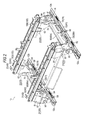
Fig. 2 is a perspective view of the seat slide device; -
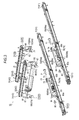
Fig. 3 is an exploded perspective view of the seat slide device; -
Fig. 4 is a cross-sectional view of a first slide rail; -
Fig. 5 is a perspective view of a rear bracket and a second slide rail supported by the rear bracket; -
Fig. 6 is a side view illustrating the vicinity of the rear bracket; -
Fig. 7 is a cross-sectional view illustrating the vicinity of the rear bracket; -
Fig. 8 is a perspective view illustrating the vicinity of the rear bracket; -
Fig. 9 is a side view illustrating the vicinity of a front bracket; -
Fig. 10 is a cross-sectional view illustrating the vicinity of the front bracket; -
Fig. 11 is a perspective view illustrating the vicinity of the front bracket; and -
Fig. 12 is a cross-sectional view illustrating the vicinity of a load transfer member interposed between the rear bracket and a second upper rail. - Hereinafter, an embodiment relating to a vehicle seat slide device will be described with reference to the drawings.
- As illustrated in
Fig. 1 , a vehicle seat 1 includes aseat cushion 2 and a seatback 3 disposed to be tiltable with respect to a rear end portion of theseat cushion 2. Then, the seat 1 is supported on a floor F of a vehicle via aseat slide device 10. - Specifically, as illustrated in
Figs. 1 to 3 , twolower rails 11 extending in a vehicle longitudinal direction are disposed side by side in parallel on the floor F of the vehicle. In addition,upper rails 12 which are movable on the respectivelower rails 11 are respectively mounted on the lower rails 11. Then, brackets 20 (21 and 22) are respectively fixed onto the respectiveupper rails 12. - In particular, the
seat slide device 10 of the embodiment disclosed here includes afront bracket 21 which is supported by theupper rail 12 at a position on a front side of a vehicle and arear bracket 22 which is supported by theupper rail 12 at a position on a rear side of the vehicle. In addition, secondlower rails 31 extending in a vehicle width direction are respectively laid between thefront brackets 21 and therear brackets 22 which are disposed in the right and left upper rails 12. Furthermore, secondupper rails 32 which are movable on the respective secondlower rails 31 are mounted on the second lower rails 31. Then, in the embodiment disclosed here, aseat frame 2a is fixed to the second upper rails 32. - In this manner, the
seat slide device 10 of the embodiment disclosed here, includes afirst slide rail 41 and asecond slide rail 42 which are arranged in a grid pattern. Thus, this can allow adjustment of a seat position in the vehicle longitudinal direction and the vehicle width direction. - That is, the
upper rail 12 moves on thelower rail 11, thereby enabling thefirst slide rail 41 to adjust a position of the seat 1 in the vehicle longitudinal direction. Then, the secondupper rail 32 moves on the secondlower rail 31 extending in the vehicle width direction, thereby enabling thesecond slide rail 42 to adjust the position of the seat 1 in the vehicle width direction. - Next, a configuration of the
first slide rail 41 will be described. - In the embodiment disclosed here, the
lower rail 11 and theupper rail 12 which configure thefirst slide rail 41 are respectively formed through a bending process of a plate material. - Specifically, as illustrated in
Fig. 4 , thelower rail 11 includes abottom wall 51 extending in the vehicle longitudinal direction (inFig. 4 , a direction orthogonal to the paper). In addition,outer walls 52 are respectively erected in both ends in a width direction (in each drawing, a rightward-leftward direction) of thebottom wall 51. Furthermore, flange-shapedupper walls 53 folded inward in the width direction are respectively formed in an upper end of theouter walls 52. Then,inner walls 54 opposing each other in the width direction are formed in a distal end of the respectiveupper walls 53 with a predetermined distance therebetween by being respectively folded downward. - In contrast, the
upper rail 12 includes a pair ofside walls 55 extending in a vertical direction between both theinner walls 54 of thelower rail 11, and anupper wall 56 connecting therespective side walls 55 above therespective side walls 55. - In addition, the
upper rail 12 includes foldedportions 57 which are arranged inside a space surrounded by theouter walls 52, theupper wall 53, and theinner walls 54 on thelower rail 11 side by being folded upward from a lower end of therespective side walls 55. Then,multiple wheels 58 which come into contact with atrack 51a disposed on therespective bottom walls 51 on thelower rail 11 side and which roll on thetrack 51 a are respectively disposed in the folded portions 57 (refer toFig. 3 ). - That is, the
wheels 58 disposed in the respective foldedportions 57 roll, thereby causing theupper rail 12 of the embodiment disclosed here to move on thelower rail 11 in a state where thewheels 58 travel on thetrack 51 a in contact therewith. In addition, the respective foldedportions 57 are surrounded by theouter walls 52, theupper wall 53, and theinner walls 54. In this manner, a relative movement of theupper rail 12 is regulated in an upward direction and the width direction with respect to thelower rail 11. Then, in the embodiment disclosed here, this can stably maintain a positional relationship between thelower rail 11 and theupper rail 12. - As illustrated in
Figs. 1 to 3 , theseat slide device 10 of the embodiment disclosed here includes alocking mechanism 59 which can regulate the relative movement between thelower rail 11 and theupper rail 12. Thelocking mechanism 59 of the embodiment disclosed here has a known configuration in which alocking lever 59b disposed in theupper rail 12 is engaged with or disengaged from engagement portions (engagement holes) 59a formed side by side in a row along an extending direction of (theinner wall 54 of) thelower rail 11. Then, in the embodiment disclosed here, based on an operation of thelocking mechanism 59, it is possible to switch between a locked state where the relative movement is regulated between thelower rail 11 and theupper rail 12 and an unlocked state where the relative movement is allowed. - In addition, in the
seat slide device 10 of the embodiment disclosed here, theupper rail 12 has a shape where both theside walls 55 and theupper wall 56 which configure theupper rail 12 are largely cut out in afront end portion 12a and arear end portion 12b thereof. Then, theupper rail 12 of the embodiment disclosed here has a configuration in which both theside walls 55 and theupper wall 56 which remain in a center portion thereof serve as abracket support 60 so as to support the respective brackets 20 (21 and 22) upward. - Next, a fixing structure of the
respective brackets 20 with respect to theupper rail 12 will be described. - As illustrated in
Figs. 5 to 7 , in theseat slide device 10 of the embodiment disclosed here, therear bracket 22 includes first and secondvertical walls upper wall 63 connecting upper ends of bothvertical walls rear bracket 22 is configured so that bothvertical walls bracket support 60 of theupper rail 12. Therear bracket 22 of the embodiment disclosed here includes acover 64 which comes into contact with both thevertical walls bracket support 60. Then, in the embodiment disclosed here, the secondlower rail 31 configuring thesecond slide rail 42 on the rear side of the vehicle (refer toFig. 1 , right side) is fixed above theupper wall 63. - Specifically, in the
upper rail 12 of the embodiment disclosed here, acutout portion 70 which is open upward is formed near arear end 60b of thebracket support 60 by cutting out an upper end portion of theupper wall 56 and both theside walls 55 which configure thebracket support 60. In addition, a plate-shapedterminal plate 73 having aninsertion hole 72 into which abolt 71 can be inserted is disposed in therear end 60b of thebracket support 60. In the embodiment disclosed here, theterminal plate 73 is fixed to therear end 60b of thebracket support 60 in advance by means of welding. Furthermore, anut member 74 which can be screwed to thebolt 71 inserted into thebracket support 60 from therear end 60b side (inFigs. 6 and7 , right side) via theinsertion hole 72 of theterminal plate 73 is disposed in thecutout portion 70. Then, therear bracket 22 of the embodiment disclosed here is configured so that bothvertical walls bracket support 60, based on a fastening force between thebolt 71 and thenut member 74. - To be more specific, in the embodiment disclosed here, the
nut member 74 is fixed at a position on the rear side of the vehicle, inside thecutout portion 70, by means of welding. In addition, insertion holes 75 and 76 into which thebolt 71 can be inserted are respectively formed on bothvertical walls rear bracket 22. Then, in the embodiment disclosed here,insertion holes cover 64 which has a substantially U-shaped cross section and comes into contact with bothvertical walls - In the embodiment disclosed here, the first
vertical wall 61 is arranged at a position in contact with theterminal plate 73 disposed in therear end 60b of thebracket support 60. The secondvertical wall 62 is arranged at a position where thenut member 74 is interposed between the firstvertical wall 61 and the secondvertical wall 62, inside thecutout portion 70, that is, on thefront end 60a side (inFig. 6 , left side) of thebracket support 60 from thenut member 74. Then, thebolt 71 screwed into thenut member 74 is fastened, thereby causing the firstvertical wall 61 to be fastened to therear end 60b of thebracket support 60. - As illustrated in
Figs. 5 and8 , in the embodiment disclosed here, acutout portion 77 which has a flared shape of widening toward an opening side and which is open to the lower end is formed on the secondvertical wall 62. Specifically, thecutout portion 77 of the embodiment disclosed here has a pair ofslopes vertical wall 62 which serves as an opening side thereof. Then, as illustrated inFigs. 6 to 8 , the secondvertical wall 62 is fixed to thebracket support 60 in a state where thebracket support 60 is inserted into thecutout portion 77, more specifically, in a state where a bottom 77c of thecutout portion 77 is in contact with a bottom (cutout surface) of thecutout portion 70 formed in thebracket support 60. - In addition, as illustrated in
Figs. 6 and7 , theupper rail 12 of the embodiment disclosed here has asupport 78 which can support thebolt 71 screwed into thenut member 74 from below, on the front side of the vehicle from thenut member 74 disposed in thecutout portion 70, that is, at a position away from therear end 60b of thebracket support 60 to which the firstvertical wall 61 is fixed. In the embodiment disclosed here, in a state of penetrating bothside walls 55 of theupper rail 12, thesupport 78 is formed by laying a through-pin 79 serving as a shaft-shaped member between both theside walls 55. The through-pin 79 is normally disposed at a lower position which is not in contact with thebolt 71. Then, in this manner, even when a force applied to such an extent that thedistal end 71a side is pressed downward acts on thebolt 71, thesupport 78 of the embodiment disclosed here is configured so that thesupport 78 can support thedistal end 71a side of thebolt 71 from below. - Next, a fixing structure of the
front bracket 21 will be described. - As illustrated in
Figs. 3 ,9 , and10 , similar to therear bracket 22, thefront bracket 21 of the embodiment disclosed here includes third and fourthvertical walls upper wall 83 connecting upper ends of bothvertical walls front bracket 21 is also configured so that both thevertical walls bracket support 60 of theupper rail 12. Then, in the embodiment disclosed here, the secondlower rail 31 configuring thesecond slide rail 42 on the front side of the vehicle (refer toFig. 1 , left side) is fixed above theupper wall 83. - Specifically, in the embodiment disclosed here, a
second nut member 84 is disposed in thefront end 60a of thebracket support 60. In addition, in thefront bracket 21 of the embodiment disclosed here, aninsertion hole 86 into which asecond bolt 85 fixedly screwed into thesecond nut member 84 is formed on the thirdvertical wall 81. Then, in thefront bracket 21 of the embodiment disclosed here, thesecond bolt 85 fixedly screwed into thesecond nut member 84 is fastened. In this manner, the thirdvertical wall 81 is fastened to thefront end 60a of thebracket support 60. - In the embodiment disclosed here, the
second nut member 84 is fixed to thefront end 60a of thebracket support 60 in advance by means of welding. In addition, similar to therear bracket 22, acover 87 which comes into contact with bothvertical walls bracket support 60 is also disposed in thefront bracket 21. Then, aninsertion hole 87a disposed on the thirdvertical wall 81 is also formed in thecover 87. - In addition, in the
front bracket 21 of the embodiment disclosed here, acontact portion 88 which comes into contact with anupper surface 60s of thebracket support 60 is disposed on the fourthvertical wall 82. - Specifically, as illustrated in
Fig. 11 , in the embodiment disclosed here, similar to the cutout portion 77 (refer toFig. 5 ) disposed on the secondvertical wall 62 in therear bracket 22, acutout portion 89 which has a flared shape of widening toward an opening side thereof and which is open to the lower end is formed on the fourthvertical wall 82. Thecutout portion 89 also has a pair ofslopes vertical wall 82 which serves as an opening side thereof. Then, as illustrated inFigs. 9 to 11 , in the secondvertical wall 62, thebracket support 60 is inserted into thecutout portion 89. In this manner, a bottom 89c of thecutout portion 89 is configured to serve as thecontact portion 88 with respect to theupper surface 60s of thebracket support 60. - Next, a configuration of a load transfer member interposed between the
rear bracket 22 and the secondupper rail 32 configuring thesecond slide rail 42 will be described. - As illustrated in
Fig. 12 , in the embodiment disclosed here, similar to thelower rail 11 on thefirst slide rail 41 side, the secondlower rail 31 configuring thesecond slide rail 42 also includes abottom wall 91, anouter wall 92, anupper wall 93, and aninner wall 94, although shapes thereof are different. Then, the secondupper rail 32 also includes aside wall 95, anupper wall 96, and a foldedportion 97. - In the
second slide rail 42 of the embodiment disclosed here, multiple rollingelements 99 are interposed between the secondlower rail 31 and the secondupper rail 32. Then, in the embodiment disclosed here, this ensures a smooth relative movement between the secondlower rail 31 and the secondupper rail 32. - In addition, in the embodiment disclosed here, when a load applied to such an extent that the second
upper rail 32 is raised acts on the secondupper rail 32, aload transfer member 100 for transferring the load to therear bracket 22 is disposed between therear bracket 22 and the secondupper rail 32 on thesecond slide rail 42 side supported by therear bracket 22. - Specifically, in the embodiment disclosed here, a
long hole 101 extending in the extending direction (inFig. 12 , direction orthogonal to the paper) of the second upper rail 32 (and the second lower rail 31) is formed on theupper wall 63 of therear bracket 22 which supports thesecond slide rail 42 upward. Furthermore, along hole 102 which corresponds to and has the same shape as thelong hole 101 disposed on theupper wall 63 of therear bracket 22 is also formed on thebottom wall 91 of the secondlower rail 31. Then, theload transfer member 100 of the embodiment disclosed here includes ashaft 103 having a shape which can pass through the respectivelong holes upper wall 96 of the secondupper rail 32, and aflange 104 disposed on the other end side of theshaft 103 and having a shape which cannot pass through thelong hole 101 arranged below theupper wall 63 of therear bracket 22. - To be more specific, in the embodiment disclosed here, a stepped
bolt 105 in which a threaded portion is formed in asmall diameter portion 105a on the distal end side is used as theload transfer member 100. Specifically, in the steppedbolt 105, an outer diameter D1 of alarge diameter portion 105b thereof is set to have a smaller value than a groove width D0 of thelong hole 101 disposed on theupper wall 63 of the rear bracket 22 (D1<D0). An outer diameter D2 of abolt head 105c thereof is set to have a greater value than the groove width D0 of the long hole 101 (D2>D0). In the embodiment disclosed here, thelong hole 102 disposed on thebottom wall 91 of the secondlower rail 31 has a groove width DO' which is substantially equal to (slightly larger than) the groove width D0 of thelong hole 101 on therear bracket 22 side (DO≅D0'). In addition, the steppedbolt 105 is inserted into the secondupper rail 32 from a lower side of theupper wall 63 of therear bracket 22 via thelong hole 101. Then, the steppedbolt 105 is fixed to theupper wall 96 of the secondupper rail 32 by using the threaded portion formed in thesmall diameter portion 105a. - That is, in the stepped
bolt 105 of the embodiment disclosed here, thesmall diameter portion 105a and thelarge diameter portion 105b which have a shaft shape configure theshaft 103 of theload transfer member 100. Thebolt head 105c having a flange shape configures theflange 104 of theload transfer member 100. - In addition, in the embodiment disclosed here, through-
holes small diameter portion 105a of the steppedbolt 105 is inserted are formed in theupper wall 96 of the secondupper rail 32 and theseat frame 2a fixed to theupper wall 96. In the embodiment disclosed here, thesmall diameter portion 105a of the steppedbolt 105 is inserted into the through-hole 106 (outer diameter D3) formed on theupper wall 96 of the secondupper rail 32 by means of press fitting. Furthermore, thelarge diameter portion 105b of the steppedbolt 105 has an outer diameter which is larger than inner diameters D4 and D5 of the respective through-holes 106 and 107 (D1>D4, D1>D5). Then, a distal end portion of the steppedbolt 105 is fixed to theupper wall 96 of the secondupper rail 32 in a state where theseat frame 2a and theupper wall 96 of the secondupper rail 32 are co-fastened between anut 108 and thelarge diameter portion 105b, based on the fastening force of thenut 108 fixedly screwed to the threaded portion formed in thesmall diameter portion 105a. - Next, an operation of the
load transfer member 100 configured as described above will be described. - As illustrated in
Fig. 1 , aseat belt anchor 110 holding a seat belt (not illustrated) is disposed in a laterally rear end of the seat 1 of the embodiment disclosed here. Therefore, during a forward collision of a vehicle, a load applied to such an extent that the secondupper rail 32 is raised integrally with the seat 1 supported upward, that is, a separation load applied to such an extent that the secondupper rail 32 is separated from the secondlower rail 31, acts on the secondupper rail 32 of thesecond slide rail 42 arranged on the rear side of the vehicle. - In the embodiment disclosed here, when this separation load acts on the second
upper rail 32, the steppedbolt 105 fixed to theupper wall 96 is moved upward with the secondupper rail 32. In this manner, thebolt head 105c arranged below theupper wall 63 of therear bracket 22 comes into contact with theupper wall 63 via thelong hole 101 so that the separation load is transferred to therear bracket 22 via the steppedbolt 105 serving as theload transfer member 100. - As described above, according to the embodiment disclosed here, the following advantageous effects can be obtained.
- (1) The
cutout portion 70 which is open upward is formed in thebracket support 60 of theupper rail 12 by cutting out theupper wall 56 and both theside walls 55. Then, thenut member 74 which can be screwed to thebolt 71 inserted into thebracket support 60 via therear end 60b of thebracket support 60 is disposed in thecutout portion 70. In addition, therear bracket 22 includes the first and secondvertical walls bolt 71 is inserted and which oppose each other. Then, the firstvertical wall 61 is fixed to therear end 60b of thebracket support 60, based on the fastening force of thebolt 71 screwed into thenut member 74. The secondvertical wall 62 is arranged at the position where thenut member 74 is interposed between the firstvertical wall 61 and the secondvertical wall 62, inside thecutout portion 70. - According to the above-described configuration, it is possible to reduce a possibility that the respective
vertical walls bolt 71. As a result, both thevertical walls rear bracket 22 can be properly erected on thebracket support 60 of theupper rail 12. Thus, this can ensure highly improved support rigidity. In particular, during the forward collision of the vehicle, the load (separation load) applied to such an extent that therear bracket 22 is raised integrally with the seat 1 supported upward acts on therear bracket 22 arranged on the rear side of the vehicle. Therefore, by therear bracket 22 adopting the above-described fixing structure, it is possible to more reliably support the seat 1. In addition, by thenut member 74 being fixed to thebracket support 60, it is possible to reduce a possibility that contact noise may be generated between theupper rail 12 and thenut member 74 as observed in the related art. Then, this can provide improved quality. - (2) The
front bracket 21 includes the thirdvertical wall 81 which is fixed to thefront end 60a of thebracket support 60, based on the fastening force of thesecond nut member 84 which is fixed to thefront end 60a of thebracket support 60 and thesecond bolt 85 fixedly screwed into thesecond nut member 84, and the fourthvertical wall 82 which has thecontact portion 88 with respect to theupper surface 60s of thebracket support 60. - That is, during a forward collision of the vehicle which generates the greatest separation load, the seat 1 is likely to move forward in a state where the rear end side having the seatback 3 is raised. Then, in this manner, the separation load applied to such an extent that the
upper rail 12 is separated upward from therear end portion 12b side acts on thefirst slide rail 41 extending in the vehicle longitudinal direction. - That is, the separation load transferred to the
bracket support 60 via thefront bracket 21 is weaker than the separation load transferred to thebracket support 60 via therear bracket 22. Accordingly, even in a case of a fixing structure in which only the thirdvertical wall 81 side is fastened to thebracket support 60 as describe above, it is possible to ensure the support rigidity which can sufficiently withstand the separation load. Then, with regard to a normal seat load acting in a direction in which theupper rail 12 is pressed down, it is possible to stably support the seat 1 upward by distributing the seat load to the fourthvertical wall 82 having acontact portion 88 with respect to anupper surface 60s of thebracket support 60. - Furthermore, according to the above-described configuration, a bracket fixing hole (for example, the cutout portion 70) is not formed for both
side walls 55 and theupper wall 56 which configure thebracket support 60. Accordingly, it is possible to prevent the rigidity of theupper rail 12 itself from deteriorating due to forming the hole. Thus, this can allow a cross-sectional shape of theupper rail 12 to be suitably maintained. As a result, it is possible to ensure a smooth relative movement of theupper rail 12 with respect to thelower rail 11. - (3) In the
upper rail 12, thesupport 78 which can support thebolt 71 screwed into thenut member 74 from below is disposed at a position on the front side of the vehicle from thenut member 74. - That is, in a fixing structure in which only the first
vertical wall 61 side is fixed to therear end 60b of thebracket support 60 by using the fastening force of thebolt 71, when the load applied to such an extent that therear bracket 22 is raised upward acts on therear bracket 22, thebolt 71 is likely to rotate around the nut member 74 (refer toFig. 7 , in the drawing, counterclockwise direction). That is, a force of pressing thedistal end 71a side downward is applied to thebolt 71. However, according to the above-described configuration, it is possible to support thedistal end 71 a side of thebolt 71 from below by using thesupport 78 disposed in theupper rail 12. Then, this can ensure more improved support rigidity. - (4) The
long hole 101 extending in the extending direction of the second upper rail 32 (and the second lower rail 31) is disposed on theupper wall 63 of therear bracket 22. Then, theload transfer member 100 including theshaft 103 whose one end side can pass through thelong hole 101 fixed to theupper wall 96 of the secondupper rail 32, and theflange 104 which is disposed on the other end side of theshaft 103 and which cannot pass through thelong hole 101 arranged below theupper wall 63 of therear bracket 22 is interposed between therear bracket 22 and the secondupper rail 32. - According to the above-described configuration, when the separation load is applied to such an extent that the second
upper rail 32 is raised upward, the load transfer member 100 (stepped bolt 105) fixed to theupper wall 96 is likely to move upward with the secondupper rail 32. That is, the flange 104 (bolt head 105c) of theload transfer member 100 arranged below theupper wall 63 of therear bracket 22 via thelong hole 101 comes into contact with theupper wall 63. Accordingly, the separation load can be transferred to therear bracket 22. Then, this can lessen the separation load acting on the secondupper rail 32, and can suppress deformation of the secondupper rail 32. As a result, it is possible to ensure more improved support rigidity. - In addition, as observed in the load transfer member in the related art, in a configuration in which the large diameter portion which cannot pass through the long hole on the bracket side is arranged inside the second upper rail (refer to
Fig. 5 in Reference 1), there is a possibility that a gap between the second upper rail and the second lower rail may be changed due to a shaft length of the large diameter portion. Therefore, an error occurs in the shaft length, thereby causing a possibility that a rolling element interposed between the second upper rail and the second lower rail may be squeezed. This causes a possibility that smooth rolling of the rolling element may be hindered. However, according to the above-described configuration, even if the error occurs in the shaft length of theshaft 103, the gap between the secondupper rail 32 and the secondlower rail 31 is not changed. Thus, this ensures the smooth rolling of the rollingelement 99. Accordingly, the secondupper rail 32 can be relatively moved more smoothly with respect to the secondlower rail 31. - (5) The
nut member 74 is welded to thebracket support 60 at a position on the rear side of the vehicle, inside thecutout portion 70, that is, at a position on therear end 60b side to which the firstvertical wall 61 of therear bracket 22 is fixed. - According to the above-described configuration, it is possible to ensure more improved support rigidity, and it is possible to more reliably reduce a possibility that contact noise may be generated between the
nut member 74 and thebracket support 60. Then, the welding work is carried out before therear bracket 22 is assembled. Accordingly, it is possible to efficiently carry out assembly work. - (6) The
support 78 is formed by laying the through-pin 79 serving as the shaft-shaped member between both theside walls 55 in a state where the through-pin 79 penetrates both theside walls 55 of theupper rail 12. This enables a simple configuration to form thesupport 78 which can reliably support thedistal end 71 a side of thebolt 71 from below. - (7) The
terminal plate 73 serving as the plate-shaped member which has theinsertion hole 72 into which thebolt 71 is inserted is disposed in therear end 60b of thebracket support 60. In this manner, it is possible to more reliably fix the firstvertical wall 61 of therear bracket 22 to therear end 60b of thebracket support 60, based on the fastening force of thebolt 71 screwed into thenut member 74. - (8) The
cutout portions vertical wall 62 and the fourthvertical wall 82 of therespective brackets 20. - According to the above-described configuration, the
bracket support 60 is inserted into thecutout portions respective brackets 20 to be easily assembled to thebracket support 60. - The above-described embodiments may be modified as follows.
- In the above-described embodiment, the
lower rail 11 and theupper rail 12 which configure thefirst slide rail 41 extend in the vehicle longitudinal direction, and the secondlower rail 31 and the secondupper rail 32 which configure thesecond slide rail 42 extend in the vehicle width direction. However, without being limited thereto, the extending direction of thefirst slide rail 41 may not necessarily be the vehicle longitudinal direction. Furthermore, also the extending direction of thesecond slide rail 42 may not necessarily be the vehicle width direction, as long as thesecond slide rail 42 extends in a direction intersecting thefirst slide rail 41. Then, the fixing structure of therespective brackets 20 with respect to theupper rail 12 may also be applied to a case where a seat is fixed to therespective brackets 20 without interposing thesecond slide rail 42 therebetween. - In the above-described embodiment, the
upper rail 12 has a shape in which both theside walls 55 and theupper wall 56 are largely cut out in thefront end portion 12a and therear end portion 12b. Then, both theside walls 55 and theupper wall 56 which remain in the center portion serve as thebracket support 60, thereby supporting the respective brackets 20 (21 and 22) upward. However, without being limited thereto, both theside walls 55 and theupper wall 56 may have a length which is the same as that of the foldedportion 57 moving inside thelower rail 11. - In the above-described embodiment, the
seat slide device 10 includes twobrackets 20 of thefront bracket 21 and therear bracket 22. However, without being limited thereto, the number of thebrackets 20 may be one. Then, in this case, the fixing structure using therear bracket 22 according to the above-described embodiment may be adopted. In addition, the number of thebrackets 20 may be three or more. In this case, thebracket 20 arranged on the rearmost side of the vehicle may adopt the fixing structure of therear bracket 22 according to the above-described embodiment. Then, in a configuration havingmultiple brackets 20, thebracket 20 arranged on the frontmost side of the vehicle may adopt the fixing structure of therear bracket 22 according to the above-described embodiment. In this case, the "terminal of the bracket support to which the first vertical wall is fixed" is the front end of the bracket support, as a matter of course. - In the above-described embodiment, the
nut member 74 is fixed at a position on the rear side of the vehicle, inside thecutout portion 70, by means of welding. However, a configuration may be adopted in which thenut member 74 is fastened in the axial direction by the fastening force of thebolt 71. Similarly, theterminal plate 73 may also adopt a configuration in which theterminal plate 73 is co-fastened between the bolt head and therear end 60b of thebracket support 60, based on the fastening force of thebolt 71 and thenut member 74. - In the above-described embodiment, the
cutout portions vertical wall 62 and the fourthvertical wall 82 of therespective brackets 20. However, without being limited thereto, anybracket 20 may be arbitrarily selected and set to have the cutout portion formed in the lower end of the second vertical wall and the fourth vertical wall. In addition, the flared shape may be arbitrarily changed. Then, a configuration may be adopted in which the cutout portion is not disposed in the lower end of the second vertical wall and the fourth vertical wall. - In the above-described embodiment, the
load transfer member 100 is interposed between therear bracket 22 and the secondupper rail 32 on thesecond slide rail 42 side supported by therear bracket 22. However, without being limited thereto, theload transfer member 100 may be interposed between anybracket 20 and the secondupper rail 32 disposed above thebracket 20. - In addition, the
load transfer member 100 is not necessarily limited to the steppedbolt 105. Then, a shape of theshaft 103 and theflange 104 may also be arbitrarily changed. - In the above-described embodiment, the
long hole 102 which corresponds to thelong hole 101 on therear bracket 22 side and has substantially the same shape is formed on thebottom wall 91 of the secondlower rail 31. Thelong hole 102 has the groove width D0' which is substantially equal to the groove width D0 of thelong hole 101 on therear bracket 22 side. However, without being limited thereto, as long as the relative movement of theshaft 103 of theload transfer member 100 is not hindered with respect to thelong hole 101 on therear bracket 22 side, a hole shape of thelong hole 102 formed on thebottom wall 91 of the secondlower rail 31 may be arbitrarily changed. - In the above-described embodiment, the
support 78 is formed by laying the through-pin 79 serving as the shaft-shaped member between both theside walls 55 in a state where the through-pin 79 penetrates both theside walls 55 of theupper rail 12. However, without being limited thereto, the configuration of thesupport 78 may be arbitrarily changed. - In the above-described embodiment, the respective brackets 20 (21 and 22) respectively include the covers (64 and 87). However, a configuration without these covers may be adopted.
- Next, technical ideas and advantageous effects which can be understood from the above-described embodiments will be described.
- (a) In the vehicle seat slide device, the nut member is welded to the bracket support at the position on the terminal side to which the first vertical wall is fixed, inside the cutout portion.
- According to the above-described configuration, it is possible to ensure more improved support rigidity, and it is possible to more reliably reduce a possibility that contact noise may be generated between the nut member and the bracket support. Then, the welding work is carried out before the bracket is assembled. Accordingly, it is possible to efficiently carry out assembly work.
- (b) In the vehicle seat slide device, the support is the shaft-shaped member which is laid between both the side walls. This enables a simple configuration to form the support which can reliably support the distal end side of the bolt from below.
- (c) In the vehicle seat slide device, the plate-shaped member having the insertion hole into which the bolt is inserted is disposed in the terminal of the bracket support to which the first vertical wall is fixed. In this manner, it is possible to more reliably fix the first vertical wall of the bracket to the terminal of the bracket support, based on the fastening force of the bolt screwed into the nut member.
- (d) In the vehicle seat slide device, the cutout portion which has the flared shape of widening toward the opening side and is open to the lower end is formed on the second vertical wall. The bracket support is inserted into the cutout portion disposed in the lower end of the second vertical wall, thereby enabling the bracket to be easily assembled to the bracket support.
- The principles, preferred embodiment and mode of operation of the present invention have been described in the foregoing specification. However, the invention which is intended to be protected is not to be construed as limited to the particular embodiments disclosed. Further, the embodiments described herein are to be regarded as illustrative rather than restrictive. Variations and changes may be made by others, and equivalents employed, without departing from the scope of the present invention. Accordingly, it is expressly intended that all such variations, changes and equivalents which fall within the scope of the present invention as defined in the claims, be embraced thereby.
Claims (9)
- A vehicle seat slide device (10) comprising:an upper rail (12) that includes a bracket support (60) having a pair of side walls (55) and an upper wall (56) connecting upper ends of the respective side walls;a lower rail (11) that supports the upper rail so as to be relatively movable; anda bracket (20) that is fixed to the bracket support,wherein a cutout portion (70) which is open upward is formed in the bracket support (60) by cutting out the upper wall (56) and the respective side walls (55),wherein a nut member (74) which is screwed to a bolt (71) inserted into the bracket support (60) via a terminal (73) of the bracket support is disposed in the cutout portion (70),wherein the bracket (20) includes first and second vertical walls (61, 62) which have an insertion hole (72) into which the bolt is inserted, and which oppose each other,wherein the first vertical wall (61) is fixed to the terminal (73) of the bracket support (60), based on a fastening force of the bolt (71) screwed into the nut member (74), andwherein the second vertical wall (62) is arranged inside the cutout portion (70) at a position where the nut member (74) is interposed between the first vertical wall (61) and the second vertical wall (62).
- The vehicle seat slide device according to claim 1,
wherein the terminal (73) of the bracket support (60) to which the first vertical wall (61) is fixed is a rear end of the bracket support (60) extending in a vehicle longitudinal direction. - The vehicle seat slide device according to claim 2, further comprising:a front bracket (21) that is fixed to a front end side of the bracket support (60),wherein the front bracket includes,
a third vertical wall (81) which is fixed to the front end of the bracket support (60), based on a fastening force of a second nut member (84) which is fixed to a front end of the bracket support (60) and a second bolt (85) fixedly screwed into the second nut member (84), and
a fourth vertical wall (82) which has a contact portion with respect to an upper surface of the bracket support (60). - The vehicle seat slide device according to any one of claims 1 to 3,
wherein in the upper rail, a support (78) which support the bolt (71) screwed into the nut member (74) from below is disposed at a position farther away from the first vertical wall (61) than the nut member (74). - The vehicle seat slide device according to claim 4,
wherein the support is a shaft-shaped member (79) which is laid between both the side walls (55). - The vehicle seat slide device according to any one of claims 1 to 5,
wherein the bracket (20) supports a second upper rail (32) and a second lower rail (31) which have an upper wall (63) connecting the first and second vertical walls (61, 62), and which extend in a direction intersecting the extending direction of the upper rail (12) and the lower rail (11) above the upper wall;
a long hole (101) extending in the extending direction of the second upper rail (32) is disposed on the upper wall (63) of the bracket (20); and
a load transfer member (100) including a shaft (103) having a shape which can pass through the long hole (101) and whose one end side is fixed to the upper wall (96) of the second upper rail (32), and a flange (104) disposed on the other end side of the shaft (103) and having a shape which cannot pass through the long hole (101) arranged below the upper wall (63) of the bracket (20) is interposed between the bracket (20) and the second upper rail (32). - The vehicle seat slide device according to any one of claims 1 to 6,
wherein the nut member (74) is welded to the bracket support (60) at a position on the terminal side to which the first vertical wall (61) is fixed inside the cutout portion (70). - The vehicle seat slide device according to any one of claims 1 to 7,
wherein a plate-shaped member (73) having an insertion hole (72) into which the bolt (71) is inserted is disposed in the terminal of the bracket support (60) to which the first vertical wall (61) is fixed. - The vehicle seat slide device according to any one of claims 1 to 8,
wherein a cutout portion (77, 89) which has a flared shape of widening toward an opening side and which is open to a lower end is formed on the second vertical wall (62).
Applications Claiming Priority (1)
| Application Number | Priority Date | Filing Date | Title |
|---|---|---|---|
| JP2013236294A JP6225656B2 (en) | 2013-11-14 | 2013-11-14 | Vehicle seat slide device |
Publications (2)
| Publication Number | Publication Date |
|---|---|
| EP2873552A1 true EP2873552A1 (en) | 2015-05-20 |
| EP2873552B1 EP2873552B1 (en) | 2016-07-20 |
Family
ID=51900244
Family Applications (1)
| Application Number | Title | Priority Date | Filing Date |
|---|---|---|---|
| EP14193069.3A Active EP2873552B1 (en) | 2013-11-14 | 2014-11-13 | Vehicle seat slide device |
Country Status (4)
| Country | Link |
|---|---|
| US (1) | US9321374B2 (en) |
| EP (1) | EP2873552B1 (en) |
| JP (1) | JP6225656B2 (en) |
| CN (1) | CN204249842U (en) |
Cited By (2)
| Publication number | Priority date | Publication date | Assignee | Title |
|---|---|---|---|---|
| CN106494268A (en) * | 2015-09-07 | 2017-03-15 | 丰田纺织株式会社 | Sliding position detection means for vehicle seat |
| WO2020250061A1 (en) * | 2019-06-11 | 2020-12-17 | Italdesign-Giugiaro S.P.A. | System for positioning a component on the floor of the passenger compartment of a vehicle |
Families Citing this family (12)
| Publication number | Priority date | Publication date | Assignee | Title |
|---|---|---|---|---|
| CN104870247B (en) * | 2012-12-27 | 2017-05-24 | 提爱思科技股份有限公司 | Seat device |
| JP6189249B2 (en) * | 2014-04-25 | 2017-08-30 | トヨタ紡織株式会社 | Vehicle seat |
| JP6001004B2 (en) * | 2014-04-25 | 2016-10-05 | トヨタ紡織株式会社 | Vehicle seat |
| JP6365314B2 (en) * | 2015-01-16 | 2018-08-01 | トヨタ紡織株式会社 | Vehicle seat |
| DE102016224588B4 (en) * | 2015-12-15 | 2023-09-21 | Lear Corporation | Rail assembly |
| DE102016224663B4 (en) | 2015-12-15 | 2019-11-21 | Lear Corporation | rail arrangement |
| US9849808B2 (en) | 2016-03-08 | 2017-12-26 | Honda Motor Co., Ltd. | End bracket for lateral slide rail for removable seat |
| US10005376B2 (en) * | 2016-03-08 | 2018-06-26 | Honda Motor Co., Ltd. | Vehicle seat |
| JP6809375B2 (en) * | 2017-05-22 | 2021-01-06 | トヨタ紡織株式会社 | Fastening structure for vehicle seats and fasteners for vehicle seats |
| JP6978666B2 (en) * | 2017-08-02 | 2021-12-08 | テイ・エス テック株式会社 | Reinforcing structure of the seat frame |
| US11505021B2 (en) * | 2021-02-03 | 2022-11-22 | GM Global Technology Operations LLC | Multi-tiered body frame integral structure for off road vehicles |
| WO2025129420A1 (en) | 2023-12-19 | 2025-06-26 | Brose Fahrzeugteile SE & Co. Kommanditgesellschaft, Coburg | Vehicle seat arrangement |
Citations (9)
| Publication number | Priority date | Publication date | Assignee | Title |
|---|---|---|---|---|
| JPH066074U (en) * | 1992-06-30 | 1994-01-25 | 株式会社タチエス | Fixing structure for slide rails of automobile seats |
| US6264159B1 (en) * | 2000-01-05 | 2001-07-24 | Pro-Glory Enterprises Co., Ltd. | Universal car seat-adjusting slide rail structure |
| DE20115164U1 (en) * | 2001-09-13 | 2002-02-14 | Brose Fahrzeugteile GmbH & Co. Kommanditgesellschaft, Coburg, 96450 Coburg | Guide rail for a motor vehicle seat |
| EP1228922A1 (en) * | 2001-01-31 | 2002-08-07 | Johnson Controls Automotive Systems Corporation | Vehicle seat assembly |
| JP2004090765A (en) * | 2002-08-30 | 2004-03-25 | Aisin Seiki Co Ltd | Vehicle seat device |
| FR2930203A1 (en) * | 2008-04-22 | 2009-10-23 | Faurecia Sieges Automobile | Slide for seat of motor vehicle, has projecting member comprising retaining element supported on lower surface of core and locking orifice in which stamping portion integrated to side flank of central part of movable profile is inserted |
| EP2213505A2 (en) * | 2009-01-29 | 2010-08-04 | Aisin Seiki Kabushiki Kaisha | Seat apparatus for vehicle |
| JP2010173487A (en) | 2009-01-29 | 2010-08-12 | Aisin Seiki Co Ltd | Seat device for vehicle |
| CN202966010U (en) * | 2011-11-25 | 2013-06-05 | 丰田纺织株式会社 | Seat for car |
Family Cites Families (11)
| Publication number | Priority date | Publication date | Assignee | Title |
|---|---|---|---|---|
| JPH11189076A (en) * | 1997-12-25 | 1999-07-13 | Aisin Seiki Co Ltd | Vehicle seat slide device |
| US6405987B1 (en) * | 1999-08-05 | 2002-06-18 | Dura Global Technologies, Inc. | Reinforcement member for a seat mounting assembly |
| JP5023806B2 (en) | 2007-05-21 | 2012-09-12 | マツダ株式会社 | Vehicle seat slide device |
| JP5374073B2 (en) | 2008-06-02 | 2013-12-25 | デルタ工業株式会社 | Vehicle seat |
| JP5434102B2 (en) * | 2009-01-29 | 2014-03-05 | アイシン精機株式会社 | Vehicle seat slide device |
| JP5434100B2 (en) | 2009-01-29 | 2014-03-05 | アイシン精機株式会社 | Rotating seat device for vehicle |
| JP5434101B2 (en) | 2009-01-29 | 2014-03-05 | アイシン精機株式会社 | Rotating seat device for vehicle |
| EP2213504A3 (en) | 2009-01-29 | 2017-12-27 | Aisin Seiki Kabushiki Kaisha | Rotating seat apparatus for vehicle |
| JP5396887B2 (en) * | 2009-01-29 | 2014-01-22 | アイシン精機株式会社 | Vehicle seat slide device |
| DE102010047043B4 (en) * | 2010-09-30 | 2021-05-06 | Adient Luxembourg Holding S.À R.L. | Longitudinal adjuster and vehicle seat |
| JP5787368B2 (en) * | 2012-02-13 | 2015-09-30 | トヨタ車体株式会社 | Seat slide device |
-
2013
- 2013-11-14 JP JP2013236294A patent/JP6225656B2/en active Active
-
2014
- 2014-11-12 CN CN201420681813.7U patent/CN204249842U/en not_active Expired - Lifetime
- 2014-11-13 EP EP14193069.3A patent/EP2873552B1/en active Active
- 2014-11-14 US US14/541,503 patent/US9321374B2/en active Active
Patent Citations (9)
| Publication number | Priority date | Publication date | Assignee | Title |
|---|---|---|---|---|
| JPH066074U (en) * | 1992-06-30 | 1994-01-25 | 株式会社タチエス | Fixing structure for slide rails of automobile seats |
| US6264159B1 (en) * | 2000-01-05 | 2001-07-24 | Pro-Glory Enterprises Co., Ltd. | Universal car seat-adjusting slide rail structure |
| EP1228922A1 (en) * | 2001-01-31 | 2002-08-07 | Johnson Controls Automotive Systems Corporation | Vehicle seat assembly |
| DE20115164U1 (en) * | 2001-09-13 | 2002-02-14 | Brose Fahrzeugteile GmbH & Co. Kommanditgesellschaft, Coburg, 96450 Coburg | Guide rail for a motor vehicle seat |
| JP2004090765A (en) * | 2002-08-30 | 2004-03-25 | Aisin Seiki Co Ltd | Vehicle seat device |
| FR2930203A1 (en) * | 2008-04-22 | 2009-10-23 | Faurecia Sieges Automobile | Slide for seat of motor vehicle, has projecting member comprising retaining element supported on lower surface of core and locking orifice in which stamping portion integrated to side flank of central part of movable profile is inserted |
| EP2213505A2 (en) * | 2009-01-29 | 2010-08-04 | Aisin Seiki Kabushiki Kaisha | Seat apparatus for vehicle |
| JP2010173487A (en) | 2009-01-29 | 2010-08-12 | Aisin Seiki Co Ltd | Seat device for vehicle |
| CN202966010U (en) * | 2011-11-25 | 2013-06-05 | 丰田纺织株式会社 | Seat for car |
Cited By (4)
| Publication number | Priority date | Publication date | Assignee | Title |
|---|---|---|---|---|
| CN106494268A (en) * | 2015-09-07 | 2017-03-15 | 丰田纺织株式会社 | Sliding position detection means for vehicle seat |
| CN106494268B (en) * | 2015-09-07 | 2019-01-04 | 丰田纺织株式会社 | Sliding position detection device for vehicle seat |
| WO2020250061A1 (en) * | 2019-06-11 | 2020-12-17 | Italdesign-Giugiaro S.P.A. | System for positioning a component on the floor of the passenger compartment of a vehicle |
| US11639118B2 (en) | 2019-06-11 | 2023-05-02 | Italdesign-Giugiaro S.P.A. | System for positioning a component on the floor of the passenger compartment of a vehicle |
Also Published As
| Publication number | Publication date |
|---|---|
| JP2015093664A (en) | 2015-05-18 |
| CN204249842U (en) | 2015-04-08 |
| EP2873552B1 (en) | 2016-07-20 |
| JP6225656B2 (en) | 2017-11-08 |
| US20150129737A1 (en) | 2015-05-14 |
| US9321374B2 (en) | 2016-04-26 |
Similar Documents
| Publication | Publication Date | Title |
|---|---|---|
| EP2873552B1 (en) | Vehicle seat slide device | |
| JP5654764B2 (en) | Sliding device for vehicle seat | |
| US9126505B2 (en) | Seat slide apparatus | |
| EP2017119B1 (en) | Seat device of vehicle and control method therefor | |
| JP6255049B2 (en) | Vehicle seat mounting device | |
| US9238422B2 (en) | Vehicle seat sliding apparatus | |
| CN106994922B (en) | Children's seat | |
| US9327616B2 (en) | Vehicle seat sliding apparatus | |
| US20110278420A1 (en) | Slide device for vehicle seat | |
| JP2019093743A (en) | Seat structure for vehicle | |
| US20140231610A1 (en) | Vehicle seat sliding apparatus | |
| US9387779B2 (en) | Seat track assembly having selectable end stop positions | |
| KR101607103B1 (en) | Unlocking device for a vehicle seat with an entry facilitation function and method for operating an unlocking device | |
| JP2009073398A (en) | Vehicle seat slide device | |
| DE112014003927T5 (en) | vehicle seat | |
| EP4335745A1 (en) | Aircraft seat with energy attenuating metering plate | |
| CN109715438A (en) | Guide rail and vehicle seat | |
| JP6614028B2 (en) | Seat cushion adjustment device | |
| JP2019068563A (en) | Wire harness wiring device | |
| US9663009B2 (en) | Conveyance seat | |
| WO2017022341A1 (en) | Seat sliding apparatus for a vehicle | |
| JP2013112041A (en) | Vehicular seat | |
| JP5692153B2 (en) | Vehicle seat device | |
| JP2014083888A (en) | Sheet slide device for vehicle | |
| JP6390288B2 (en) | Seat back frame structure |
Legal Events
| Date | Code | Title | Description |
|---|---|---|---|
| PUAI | Public reference made under article 153(3) epc to a published international application that has entered the european phase |
Free format text: ORIGINAL CODE: 0009012 |
|
| 17P | Request for examination filed |
Effective date: 20141113 |
|
| AK | Designated contracting states |
Kind code of ref document: A1 Designated state(s): AL AT BE BG CH CY CZ DE DK EE ES FI FR GB GR HR HU IE IS IT LI LT LU LV MC MK MT NL NO PL PT RO RS SE SI SK SM TR |
|
| AX | Request for extension of the european patent |
Extension state: BA ME |
|
| R17P | Request for examination filed (corrected) |
Effective date: 20150914 |
|
| RBV | Designated contracting states (corrected) |
Designated state(s): AL AT BE BG CH CY CZ DE DK EE ES FI FR GB GR HR HU IE IS IT LI LT LU LV MC MK MT NL NO PL PT RO RS SE SI SK SM TR |
|
| GRAP | Despatch of communication of intention to grant a patent |
Free format text: ORIGINAL CODE: EPIDOSNIGR1 |
|
| RIC1 | Information provided on ipc code assigned before grant |
Ipc: B60N 2/06 20060101ALI20160203BHEP Ipc: B60N 2/07 20060101AFI20160203BHEP Ipc: B60N 2/68 20060101ALI20160203BHEP |
|
| INTG | Intention to grant announced |
Effective date: 20160229 |
|
| GRAS | Grant fee paid |
Free format text: ORIGINAL CODE: EPIDOSNIGR3 |
|
| GRAA | (expected) grant |
Free format text: ORIGINAL CODE: 0009210 |
|
| AK | Designated contracting states |
Kind code of ref document: B1 Designated state(s): AL AT BE BG CH CY CZ DE DK EE ES FI FR GB GR HR HU IE IS IT LI LT LU LV MC MK MT NL NO PL PT RO RS SE SI SK SM TR |
|
| REG | Reference to a national code |
Ref country code: GB Ref legal event code: FG4D |
|
| REG | Reference to a national code |
Ref country code: CH Ref legal event code: EP |
|
| REG | Reference to a national code |
Ref country code: IE Ref legal event code: FG4D |
|
| REG | Reference to a national code |
Ref country code: AT Ref legal event code: REF Ref document number: 813773 Country of ref document: AT Kind code of ref document: T Effective date: 20160815 |
|
| REG | Reference to a national code |
Ref country code: DE Ref legal event code: R096 Ref document number: 602014002765 Country of ref document: DE |
|
| REG | Reference to a national code |
Ref country code: FR Ref legal event code: PLFP Year of fee payment: 3 |
|
| REG | Reference to a national code |
Ref country code: LT Ref legal event code: MG4D |
|
| REG | Reference to a national code |
Ref country code: NL Ref legal event code: MP Effective date: 20160720 |
|
| REG | Reference to a national code |
Ref country code: AT Ref legal event code: MK05 Ref document number: 813773 Country of ref document: AT Kind code of ref document: T Effective date: 20160720 |
|
| PG25 | Lapsed in a contracting state [announced via postgrant information from national office to epo] |
Ref country code: IS Free format text: LAPSE BECAUSE OF FAILURE TO SUBMIT A TRANSLATION OF THE DESCRIPTION OR TO PAY THE FEE WITHIN THE PRESCRIBED TIME-LIMIT Effective date: 20161120 Ref country code: IT Free format text: LAPSE BECAUSE OF FAILURE TO SUBMIT A TRANSLATION OF THE DESCRIPTION OR TO PAY THE FEE WITHIN THE PRESCRIBED TIME-LIMIT Effective date: 20160720 Ref country code: FI Free format text: LAPSE BECAUSE OF FAILURE TO SUBMIT A TRANSLATION OF THE DESCRIPTION OR TO PAY THE FEE WITHIN THE PRESCRIBED TIME-LIMIT Effective date: 20160720 Ref country code: LT Free format text: LAPSE BECAUSE OF FAILURE TO SUBMIT A TRANSLATION OF THE DESCRIPTION OR TO PAY THE FEE WITHIN THE PRESCRIBED TIME-LIMIT Effective date: 20160720 Ref country code: RS Free format text: LAPSE BECAUSE OF FAILURE TO SUBMIT A TRANSLATION OF THE DESCRIPTION OR TO PAY THE FEE WITHIN THE PRESCRIBED TIME-LIMIT Effective date: 20160720 Ref country code: NO Free format text: LAPSE BECAUSE OF FAILURE TO SUBMIT A TRANSLATION OF THE DESCRIPTION OR TO PAY THE FEE WITHIN THE PRESCRIBED TIME-LIMIT Effective date: 20161020 Ref country code: HR Free format text: LAPSE BECAUSE OF FAILURE TO SUBMIT A TRANSLATION OF THE DESCRIPTION OR TO PAY THE FEE WITHIN THE PRESCRIBED TIME-LIMIT Effective date: 20160720 Ref country code: NL Free format text: LAPSE BECAUSE OF FAILURE TO SUBMIT A TRANSLATION OF THE DESCRIPTION OR TO PAY THE FEE WITHIN THE PRESCRIBED TIME-LIMIT Effective date: 20160720 |
|
| PG25 | Lapsed in a contracting state [announced via postgrant information from national office to epo] |
Ref country code: LV Free format text: LAPSE BECAUSE OF FAILURE TO SUBMIT A TRANSLATION OF THE DESCRIPTION OR TO PAY THE FEE WITHIN THE PRESCRIBED TIME-LIMIT Effective date: 20160720 Ref country code: BE Free format text: LAPSE BECAUSE OF NON-PAYMENT OF DUE FEES Effective date: 20160720 Ref country code: GR Free format text: LAPSE BECAUSE OF FAILURE TO SUBMIT A TRANSLATION OF THE DESCRIPTION OR TO PAY THE FEE WITHIN THE PRESCRIBED TIME-LIMIT Effective date: 20161021 Ref country code: SE Free format text: LAPSE BECAUSE OF FAILURE TO SUBMIT A TRANSLATION OF THE DESCRIPTION OR TO PAY THE FEE WITHIN THE PRESCRIBED TIME-LIMIT Effective date: 20160720 Ref country code: ES Free format text: LAPSE BECAUSE OF FAILURE TO SUBMIT A TRANSLATION OF THE DESCRIPTION OR TO PAY THE FEE WITHIN THE PRESCRIBED TIME-LIMIT Effective date: 20160720 Ref country code: PL Free format text: LAPSE BECAUSE OF FAILURE TO SUBMIT A TRANSLATION OF THE DESCRIPTION OR TO PAY THE FEE WITHIN THE PRESCRIBED TIME-LIMIT Effective date: 20160720 Ref country code: AT Free format text: LAPSE BECAUSE OF FAILURE TO SUBMIT A TRANSLATION OF THE DESCRIPTION OR TO PAY THE FEE WITHIN THE PRESCRIBED TIME-LIMIT Effective date: 20160720 Ref country code: PT Free format text: LAPSE BECAUSE OF FAILURE TO SUBMIT A TRANSLATION OF THE DESCRIPTION OR TO PAY THE FEE WITHIN THE PRESCRIBED TIME-LIMIT Effective date: 20161121 |
|
| REG | Reference to a national code |
Ref country code: DE Ref legal event code: R097 Ref document number: 602014002765 Country of ref document: DE |
|
| PG25 | Lapsed in a contracting state [announced via postgrant information from national office to epo] |
Ref country code: EE Free format text: LAPSE BECAUSE OF FAILURE TO SUBMIT A TRANSLATION OF THE DESCRIPTION OR TO PAY THE FEE WITHIN THE PRESCRIBED TIME-LIMIT Effective date: 20160720 Ref country code: RO Free format text: LAPSE BECAUSE OF FAILURE TO SUBMIT A TRANSLATION OF THE DESCRIPTION OR TO PAY THE FEE WITHIN THE PRESCRIBED TIME-LIMIT Effective date: 20160720 |
|
| PLBE | No opposition filed within time limit |
Free format text: ORIGINAL CODE: 0009261 |
|
| STAA | Information on the status of an ep patent application or granted ep patent |
Free format text: STATUS: NO OPPOSITION FILED WITHIN TIME LIMIT |
|
| PG25 | Lapsed in a contracting state [announced via postgrant information from national office to epo] |
Ref country code: CZ Free format text: LAPSE BECAUSE OF FAILURE TO SUBMIT A TRANSLATION OF THE DESCRIPTION OR TO PAY THE FEE WITHIN THE PRESCRIBED TIME-LIMIT Effective date: 20160720 Ref country code: SK Free format text: LAPSE BECAUSE OF FAILURE TO SUBMIT A TRANSLATION OF THE DESCRIPTION OR TO PAY THE FEE WITHIN THE PRESCRIBED TIME-LIMIT Effective date: 20160720 Ref country code: DK Free format text: LAPSE BECAUSE OF FAILURE TO SUBMIT A TRANSLATION OF THE DESCRIPTION OR TO PAY THE FEE WITHIN THE PRESCRIBED TIME-LIMIT Effective date: 20160720 Ref country code: BG Free format text: LAPSE BECAUSE OF FAILURE TO SUBMIT A TRANSLATION OF THE DESCRIPTION OR TO PAY THE FEE WITHIN THE PRESCRIBED TIME-LIMIT Effective date: 20161020 Ref country code: SM Free format text: LAPSE BECAUSE OF FAILURE TO SUBMIT A TRANSLATION OF THE DESCRIPTION OR TO PAY THE FEE WITHIN THE PRESCRIBED TIME-LIMIT Effective date: 20160720 |
|
| 26N | No opposition filed |
Effective date: 20170421 |
|
| REG | Reference to a national code |
Ref country code: IE Ref legal event code: MM4A |
|
| PG25 | Lapsed in a contracting state [announced via postgrant information from national office to epo] |
Ref country code: SI Free format text: LAPSE BECAUSE OF FAILURE TO SUBMIT A TRANSLATION OF THE DESCRIPTION OR TO PAY THE FEE WITHIN THE PRESCRIBED TIME-LIMIT Effective date: 20160720 |
|
| PG25 | Lapsed in a contracting state [announced via postgrant information from national office to epo] |
Ref country code: LU Free format text: LAPSE BECAUSE OF NON-PAYMENT OF DUE FEES Effective date: 20161130 |
|
| REG | Reference to a national code |
Ref country code: FR Ref legal event code: PLFP Year of fee payment: 4 |
|
| PG25 | Lapsed in a contracting state [announced via postgrant information from national office to epo] |
Ref country code: IE Free format text: LAPSE BECAUSE OF NON-PAYMENT OF DUE FEES Effective date: 20161113 |
|
| PG25 | Lapsed in a contracting state [announced via postgrant information from national office to epo] |
Ref country code: HU Free format text: LAPSE BECAUSE OF FAILURE TO SUBMIT A TRANSLATION OF THE DESCRIPTION OR TO PAY THE FEE WITHIN THE PRESCRIBED TIME-LIMIT; INVALID AB INITIO Effective date: 20141113 |
|
| PG25 | Lapsed in a contracting state [announced via postgrant information from national office to epo] |
Ref country code: MC Free format text: LAPSE BECAUSE OF FAILURE TO SUBMIT A TRANSLATION OF THE DESCRIPTION OR TO PAY THE FEE WITHIN THE PRESCRIBED TIME-LIMIT Effective date: 20160720 Ref country code: MK Free format text: LAPSE BECAUSE OF FAILURE TO SUBMIT A TRANSLATION OF THE DESCRIPTION OR TO PAY THE FEE WITHIN THE PRESCRIBED TIME-LIMIT Effective date: 20160720 Ref country code: CY Free format text: LAPSE BECAUSE OF FAILURE TO SUBMIT A TRANSLATION OF THE DESCRIPTION OR TO PAY THE FEE WITHIN THE PRESCRIBED TIME-LIMIT Effective date: 20160720 |
|
| PG25 | Lapsed in a contracting state [announced via postgrant information from national office to epo] |
Ref country code: CH Free format text: LAPSE BECAUSE OF NON-PAYMENT OF DUE FEES Effective date: 20171130 Ref country code: LI Free format text: LAPSE BECAUSE OF NON-PAYMENT OF DUE FEES Effective date: 20171130 |
|
| PG25 | Lapsed in a contracting state [announced via postgrant information from national office to epo] |
Ref country code: MT Free format text: LAPSE BECAUSE OF NON-PAYMENT OF DUE FEES Effective date: 20161113 |
|
| REG | Reference to a national code |
Ref country code: FR Ref legal event code: PLFP Year of fee payment: 5 |
|
| PG25 | Lapsed in a contracting state [announced via postgrant information from national office to epo] |
Ref country code: TR Free format text: LAPSE BECAUSE OF FAILURE TO SUBMIT A TRANSLATION OF THE DESCRIPTION OR TO PAY THE FEE WITHIN THE PRESCRIBED TIME-LIMIT Effective date: 20160720 Ref country code: AL Free format text: LAPSE BECAUSE OF FAILURE TO SUBMIT A TRANSLATION OF THE DESCRIPTION OR TO PAY THE FEE WITHIN THE PRESCRIBED TIME-LIMIT Effective date: 20160720 |
|
| GBPC | Gb: european patent ceased through non-payment of renewal fee |
Effective date: 20181113 |
|
| PG25 | Lapsed in a contracting state [announced via postgrant information from national office to epo] |
Ref country code: GB Free format text: LAPSE BECAUSE OF NON-PAYMENT OF DUE FEES Effective date: 20181113 |
|
| REG | Reference to a national code |
Ref country code: DE Ref legal event code: R081 Ref document number: 602014002765 Country of ref document: DE Owner name: TOYOTA BOSHOKU KABUSHIKI KAISHA, KARIYA-SHI, JP Free format text: FORMER OWNER: AISIN SEIKI KABUSHIKI KAISHA, KARIYA-SHI, AICHI-KEN, JP |
|
| PGFP | Annual fee paid to national office [announced via postgrant information from national office to epo] |
Ref country code: FR Payment date: 20250930 Year of fee payment: 12 |
|
| PGFP | Annual fee paid to national office [announced via postgrant information from national office to epo] |
Ref country code: DE Payment date: 20250930 Year of fee payment: 12 |