EP2873551A2 - Driving apparatus for electric vehicle - Google Patents
Driving apparatus for electric vehicle Download PDFInfo
- Publication number
- EP2873551A2 EP2873551A2 EP14161775.3A EP14161775A EP2873551A2 EP 2873551 A2 EP2873551 A2 EP 2873551A2 EP 14161775 A EP14161775 A EP 14161775A EP 2873551 A2 EP2873551 A2 EP 2873551A2
- Authority
- EP
- European Patent Office
- Prior art keywords
- battery
- inverter
- motor
- electric vehicle
- driving apparatus
- Prior art date
- Legal status (The legal status is an assumption and is not a legal conclusion. Google has not performed a legal analysis and makes no representation as to the accuracy of the status listed.)
- Granted
Links
Images





Classifications
-
- B—PERFORMING OPERATIONS; TRANSPORTING
- B60—VEHICLES IN GENERAL
- B60L—PROPULSION OF ELECTRICALLY-PROPELLED VEHICLES; SUPPLYING ELECTRIC POWER FOR AUXILIARY EQUIPMENT OF ELECTRICALLY-PROPELLED VEHICLES; ELECTRODYNAMIC BRAKE SYSTEMS FOR VEHICLES IN GENERAL; MAGNETIC SUSPENSION OR LEVITATION FOR VEHICLES; MONITORING OPERATING VARIABLES OF ELECTRICALLY-PROPELLED VEHICLES; ELECTRIC SAFETY DEVICES FOR ELECTRICALLY-PROPELLED VEHICLES
- B60L15/00—Methods, circuits, or devices for controlling the traction-motor speed of electrically-propelled vehicles
- B60L15/20—Methods, circuits, or devices for controlling the traction-motor speed of electrically-propelled vehicles for control of the vehicle or its driving motor to achieve a desired performance, e.g. speed, torque, programmed variation of speed
-
- B—PERFORMING OPERATIONS; TRANSPORTING
- B60—VEHICLES IN GENERAL
- B60L—PROPULSION OF ELECTRICALLY-PROPELLED VEHICLES; SUPPLYING ELECTRIC POWER FOR AUXILIARY EQUIPMENT OF ELECTRICALLY-PROPELLED VEHICLES; ELECTRODYNAMIC BRAKE SYSTEMS FOR VEHICLES IN GENERAL; MAGNETIC SUSPENSION OR LEVITATION FOR VEHICLES; MONITORING OPERATING VARIABLES OF ELECTRICALLY-PROPELLED VEHICLES; ELECTRIC SAFETY DEVICES FOR ELECTRICALLY-PROPELLED VEHICLES
- B60L15/00—Methods, circuits, or devices for controlling the traction-motor speed of electrically-propelled vehicles
- B60L15/007—Physical arrangements or structures of drive train converters specially adapted for the propulsion motors of electric vehicles
-
- B—PERFORMING OPERATIONS; TRANSPORTING
- B60—VEHICLES IN GENERAL
- B60L—PROPULSION OF ELECTRICALLY-PROPELLED VEHICLES; SUPPLYING ELECTRIC POWER FOR AUXILIARY EQUIPMENT OF ELECTRICALLY-PROPELLED VEHICLES; ELECTRODYNAMIC BRAKE SYSTEMS FOR VEHICLES IN GENERAL; MAGNETIC SUSPENSION OR LEVITATION FOR VEHICLES; MONITORING OPERATING VARIABLES OF ELECTRICALLY-PROPELLED VEHICLES; ELECTRIC SAFETY DEVICES FOR ELECTRICALLY-PROPELLED VEHICLES
- B60L50/00—Electric propulsion with power supplied within the vehicle
- B60L50/10—Electric propulsion with power supplied within the vehicle using propulsion power supplied by engine-driven generators, e.g. generators driven by combustion engines
-
- B—PERFORMING OPERATIONS; TRANSPORTING
- B60—VEHICLES IN GENERAL
- B60L—PROPULSION OF ELECTRICALLY-PROPELLED VEHICLES; SUPPLYING ELECTRIC POWER FOR AUXILIARY EQUIPMENT OF ELECTRICALLY-PROPELLED VEHICLES; ELECTRODYNAMIC BRAKE SYSTEMS FOR VEHICLES IN GENERAL; MAGNETIC SUSPENSION OR LEVITATION FOR VEHICLES; MONITORING OPERATING VARIABLES OF ELECTRICALLY-PROPELLED VEHICLES; ELECTRIC SAFETY DEVICES FOR ELECTRICALLY-PROPELLED VEHICLES
- B60L50/00—Electric propulsion with power supplied within the vehicle
- B60L50/50—Electric propulsion with power supplied within the vehicle using propulsion power supplied by batteries or fuel cells
- B60L50/51—Electric propulsion with power supplied within the vehicle using propulsion power supplied by batteries or fuel cells characterised by AC-motors
-
- B—PERFORMING OPERATIONS; TRANSPORTING
- B60—VEHICLES IN GENERAL
- B60L—PROPULSION OF ELECTRICALLY-PROPELLED VEHICLES; SUPPLYING ELECTRIC POWER FOR AUXILIARY EQUIPMENT OF ELECTRICALLY-PROPELLED VEHICLES; ELECTRODYNAMIC BRAKE SYSTEMS FOR VEHICLES IN GENERAL; MAGNETIC SUSPENSION OR LEVITATION FOR VEHICLES; MONITORING OPERATING VARIABLES OF ELECTRICALLY-PROPELLED VEHICLES; ELECTRIC SAFETY DEVICES FOR ELECTRICALLY-PROPELLED VEHICLES
- B60L58/00—Methods or circuit arrangements for monitoring or controlling batteries or fuel cells, specially adapted for electric vehicles
- B60L58/10—Methods or circuit arrangements for monitoring or controlling batteries or fuel cells, specially adapted for electric vehicles for monitoring or controlling batteries
- B60L58/18—Methods or circuit arrangements for monitoring or controlling batteries or fuel cells, specially adapted for electric vehicles for monitoring or controlling batteries of two or more battery modules
- B60L58/20—Methods or circuit arrangements for monitoring or controlling batteries or fuel cells, specially adapted for electric vehicles for monitoring or controlling batteries of two or more battery modules having different nominal voltages
-
- B—PERFORMING OPERATIONS; TRANSPORTING
- B60—VEHICLES IN GENERAL
- B60L—PROPULSION OF ELECTRICALLY-PROPELLED VEHICLES; SUPPLYING ELECTRIC POWER FOR AUXILIARY EQUIPMENT OF ELECTRICALLY-PROPELLED VEHICLES; ELECTRODYNAMIC BRAKE SYSTEMS FOR VEHICLES IN GENERAL; MAGNETIC SUSPENSION OR LEVITATION FOR VEHICLES; MONITORING OPERATING VARIABLES OF ELECTRICALLY-PROPELLED VEHICLES; ELECTRIC SAFETY DEVICES FOR ELECTRICALLY-PROPELLED VEHICLES
- B60L2210/00—Converter types
- B60L2210/40—DC to AC converters
- B60L2210/46—DC to AC converters with more than three phases
-
- B—PERFORMING OPERATIONS; TRANSPORTING
- B60—VEHICLES IN GENERAL
- B60L—PROPULSION OF ELECTRICALLY-PROPELLED VEHICLES; SUPPLYING ELECTRIC POWER FOR AUXILIARY EQUIPMENT OF ELECTRICALLY-PROPELLED VEHICLES; ELECTRODYNAMIC BRAKE SYSTEMS FOR VEHICLES IN GENERAL; MAGNETIC SUSPENSION OR LEVITATION FOR VEHICLES; MONITORING OPERATING VARIABLES OF ELECTRICALLY-PROPELLED VEHICLES; ELECTRIC SAFETY DEVICES FOR ELECTRICALLY-PROPELLED VEHICLES
- B60L2220/00—Electrical machine types; Structures or applications thereof
- B60L2220/50—Structural details of electrical machines
- B60L2220/54—Windings for different functions
-
- B—PERFORMING OPERATIONS; TRANSPORTING
- B60—VEHICLES IN GENERAL
- B60L—PROPULSION OF ELECTRICALLY-PROPELLED VEHICLES; SUPPLYING ELECTRIC POWER FOR AUXILIARY EQUIPMENT OF ELECTRICALLY-PROPELLED VEHICLES; ELECTRODYNAMIC BRAKE SYSTEMS FOR VEHICLES IN GENERAL; MAGNETIC SUSPENSION OR LEVITATION FOR VEHICLES; MONITORING OPERATING VARIABLES OF ELECTRICALLY-PROPELLED VEHICLES; ELECTRIC SAFETY DEVICES FOR ELECTRICALLY-PROPELLED VEHICLES
- B60L2220/00—Electrical machine types; Structures or applications thereof
- B60L2220/50—Structural details of electrical machines
- B60L2220/58—Structural details of electrical machines with more than three phases
-
- B—PERFORMING OPERATIONS; TRANSPORTING
- B60—VEHICLES IN GENERAL
- B60L—PROPULSION OF ELECTRICALLY-PROPELLED VEHICLES; SUPPLYING ELECTRIC POWER FOR AUXILIARY EQUIPMENT OF ELECTRICALLY-PROPELLED VEHICLES; ELECTRODYNAMIC BRAKE SYSTEMS FOR VEHICLES IN GENERAL; MAGNETIC SUSPENSION OR LEVITATION FOR VEHICLES; MONITORING OPERATING VARIABLES OF ELECTRICALLY-PROPELLED VEHICLES; ELECTRIC SAFETY DEVICES FOR ELECTRICALLY-PROPELLED VEHICLES
- B60L2240/00—Control parameters of input or output; Target parameters
- B60L2240/40—Drive Train control parameters
- B60L2240/42—Drive Train control parameters related to electric machines
-
- B—PERFORMING OPERATIONS; TRANSPORTING
- B60—VEHICLES IN GENERAL
- B60L—PROPULSION OF ELECTRICALLY-PROPELLED VEHICLES; SUPPLYING ELECTRIC POWER FOR AUXILIARY EQUIPMENT OF ELECTRICALLY-PROPELLED VEHICLES; ELECTRODYNAMIC BRAKE SYSTEMS FOR VEHICLES IN GENERAL; MAGNETIC SUSPENSION OR LEVITATION FOR VEHICLES; MONITORING OPERATING VARIABLES OF ELECTRICALLY-PROPELLED VEHICLES; ELECTRIC SAFETY DEVICES FOR ELECTRICALLY-PROPELLED VEHICLES
- B60L2240/00—Control parameters of input or output; Target parameters
- B60L2240/40—Drive Train control parameters
- B60L2240/54—Drive Train control parameters related to batteries
- B60L2240/547—Voltage
-
- B—PERFORMING OPERATIONS; TRANSPORTING
- B60—VEHICLES IN GENERAL
- B60Y—INDEXING SCHEME RELATING TO ASPECTS CROSS-CUTTING VEHICLE TECHNOLOGY
- B60Y2200/00—Type of vehicle
- B60Y2200/90—Vehicles comprising electric prime movers
- B60Y2200/91—Electric vehicles
-
- Y—GENERAL TAGGING OF NEW TECHNOLOGICAL DEVELOPMENTS; GENERAL TAGGING OF CROSS-SECTIONAL TECHNOLOGIES SPANNING OVER SEVERAL SECTIONS OF THE IPC; TECHNICAL SUBJECTS COVERED BY FORMER USPC CROSS-REFERENCE ART COLLECTIONS [XRACs] AND DIGESTS
- Y02—TECHNOLOGIES OR APPLICATIONS FOR MITIGATION OR ADAPTATION AGAINST CLIMATE CHANGE
- Y02T—CLIMATE CHANGE MITIGATION TECHNOLOGIES RELATED TO TRANSPORTATION
- Y02T10/00—Road transport of goods or passengers
- Y02T10/60—Other road transportation technologies with climate change mitigation effect
- Y02T10/64—Electric machine technologies in electromobility
-
- Y—GENERAL TAGGING OF NEW TECHNOLOGICAL DEVELOPMENTS; GENERAL TAGGING OF CROSS-SECTIONAL TECHNOLOGIES SPANNING OVER SEVERAL SECTIONS OF THE IPC; TECHNICAL SUBJECTS COVERED BY FORMER USPC CROSS-REFERENCE ART COLLECTIONS [XRACs] AND DIGESTS
- Y02—TECHNOLOGIES OR APPLICATIONS FOR MITIGATION OR ADAPTATION AGAINST CLIMATE CHANGE
- Y02T—CLIMATE CHANGE MITIGATION TECHNOLOGIES RELATED TO TRANSPORTATION
- Y02T10/00—Road transport of goods or passengers
- Y02T10/60—Other road transportation technologies with climate change mitigation effect
- Y02T10/70—Energy storage systems for electromobility, e.g. batteries
-
- Y—GENERAL TAGGING OF NEW TECHNOLOGICAL DEVELOPMENTS; GENERAL TAGGING OF CROSS-SECTIONAL TECHNOLOGIES SPANNING OVER SEVERAL SECTIONS OF THE IPC; TECHNICAL SUBJECTS COVERED BY FORMER USPC CROSS-REFERENCE ART COLLECTIONS [XRACs] AND DIGESTS
- Y02—TECHNOLOGIES OR APPLICATIONS FOR MITIGATION OR ADAPTATION AGAINST CLIMATE CHANGE
- Y02T—CLIMATE CHANGE MITIGATION TECHNOLOGIES RELATED TO TRANSPORTATION
- Y02T10/00—Road transport of goods or passengers
- Y02T10/60—Other road transportation technologies with climate change mitigation effect
- Y02T10/7072—Electromobility specific charging systems or methods for batteries, ultracapacitors, supercapacitors or double-layer capacitors
-
- Y—GENERAL TAGGING OF NEW TECHNOLOGICAL DEVELOPMENTS; GENERAL TAGGING OF CROSS-SECTIONAL TECHNOLOGIES SPANNING OVER SEVERAL SECTIONS OF THE IPC; TECHNICAL SUBJECTS COVERED BY FORMER USPC CROSS-REFERENCE ART COLLECTIONS [XRACs] AND DIGESTS
- Y02—TECHNOLOGIES OR APPLICATIONS FOR MITIGATION OR ADAPTATION AGAINST CLIMATE CHANGE
- Y02T—CLIMATE CHANGE MITIGATION TECHNOLOGIES RELATED TO TRANSPORTATION
- Y02T10/00—Road transport of goods or passengers
- Y02T10/60—Other road transportation technologies with climate change mitigation effect
- Y02T10/72—Electric energy management in electromobility
-
- Y—GENERAL TAGGING OF NEW TECHNOLOGICAL DEVELOPMENTS; GENERAL TAGGING OF CROSS-SECTIONAL TECHNOLOGIES SPANNING OVER SEVERAL SECTIONS OF THE IPC; TECHNICAL SUBJECTS COVERED BY FORMER USPC CROSS-REFERENCE ART COLLECTIONS [XRACs] AND DIGESTS
- Y02—TECHNOLOGIES OR APPLICATIONS FOR MITIGATION OR ADAPTATION AGAINST CLIMATE CHANGE
- Y02T—CLIMATE CHANGE MITIGATION TECHNOLOGIES RELATED TO TRANSPORTATION
- Y02T90/00—Enabling technologies or technologies with a potential or indirect contribution to GHG emissions mitigation
- Y02T90/10—Technologies relating to charging of electric vehicles
- Y02T90/14—Plug-in electric vehicles
Definitions
- the present invention relates to a driving apparatus for an electric vehicle.
- a battery is provided in an electric vehicle in order to drive a motor for driving the vehicle and various electronic apparatuses.
- an air conditioner for air conditioning or heating is provided.
- an integrated starter generator for starting an engine and rotating a motor is provided in an electric vehicle.
- the ISG operates in a motoring mode for rotating the motor and a generating mode for generating a predetermined output voltage to charge a battery.
- a plurality of batteries having different charging voltages may be provided in the electric vehicle. At this time, each battery may be charged in the generating mode of the ISG.
- the ISG is generally configured to generate a high output voltage
- a high-voltage battery may be charged via the output voltage of the ISG but a low-voltage battery may not be charged via the output voltage of the ISG.
- a separate DC-DC converter is required.
- the DC-DC converter performs a function for decreasing the high output voltage of the ISG to a charging voltage of the low-voltage battery.
- the DC-DC converter has a heavy weight and a large volume, thereby increasing the weight of the electric vehicle and reducing an internal space for use.
- the DC-DC converter may deteriorate efficiency of the electric vehicle.
- the present invention is directed to a driving apparatus for an electric vehicle that substantially obviates one or more problems due to limitations and disadvantages of the related art.
- An object of the present invention is to provide a driving apparatus for an electric vehicle capable of selectively charging a plurality of batteries having different charging voltages without using a separate DC-DC converter.
- Another object of the present invention is to provide a driving apparatus for an electric vehicle capable of outputting required torque upon engine startup or upon normal driving by using a charging voltage of any one of a high-voltage battery and a low-voltage battery or both the charging voltages of the high-voltage battery and the low-voltage battery.
- Another object of the present invention is to provide a driving apparatus for an electric vehicle capable of charging the other batteries using any one battery in a state in which an engine is stopped.
- Another object of the present invention is to provide a driving apparatus for an electric vehicle having a low weight and a small volume and capable of making better use of a space.
- a driving apparatus for an electric vehicle including a motor including a stator having a main winding and an auxiliary winding and a rotor rotating due to magnetic interaction between the main winding and the auxiliary winding, an engine configured to selectively rotate the rotor, a motor controller including a first inverter connected to the main winding and a second inverter connected to the auxiliary winding, a first battery connected to the first inverter and configured to drive the motor or configured to be chargeable by the motor, and a second battery connected to the second inverter, configured to be chargeable by the motor, and having a charging voltage lower than that of the first battery.
- the motor controller may generate required torque via the charging voltage of at least one of the first battery and the second battery based on at least one of residual quantities of the first battery and the second battery and a driving state of the engine.
- the motor controller may charge at least one of the first battery and the second battery.
- the motor controller may generate required torque and, at the same time, charges any one battery.
- the motor controller may generate required torque via the first battery and the first inverter when the engine is driven.
- the motor controller may generate maximum torque via the first battery, the first inverter, the second battery and the second inverter.
- the motor controller may generate required torque via the first battery and the first inverter and charge the second battery via the second inverter, when the engine is driven.
- the motor controller may charge the first battery and the second battery via the first inverter and the second inverter, when the engine is driven.
- the motor controller may charge the second battery via the first inverter and the second inverter with the charging voltage of the first battery, when the engine is stopped, and the motor may operate as a transformer according to a turn ratio of the main winding to the auxiliary winding.
- the auxiliary winding may be wound using a hairpin winding method, and the auxiliary winding may be located closer to the rotor than the main winding.
- the number of switch elements of the first inverter may be equal to or greater than the number of switch elements of the second inverter, the first inverter and the second inverter may be electrically connected, a first switch for connecting an output end of the first battery and an output end of the second battery may be provided, and a second switch may be provided between the first switch and the second battery.
- the motor controller may turn the first switch on and turn the second switch off to generate required torque via the first battery, the first inverter and the second inverter.
- the motor controller may turn the first switch off and turn the second switch on to generate required torque via the first battery and the first inverter and to charge the second battery via the second inverter.
- the motor controller may turn the first switch off and turn the second switch on to charge the first battery via the first inverter and to charge the second battery via the second inverter.
- the motor controller may turn the first switch off and turn the second switch on to charge the second battery via the first inverter and the second inverter with the charging voltage of the first battery, and the motor may operate as a transformer according to a turn ratio of the main winding to the auxiliary winding.
- main winding and the auxiliary winding may be wound using a distributed winding method or a centralized winding method.
- the turn ratio of the main winding to the auxiliary winding may be 2:1 or 5:1.
- the rotor may have a field winding.
- the motor controller may further include a field current controller connected to the field winding.
- the motor controller may vector-control the first inverter and the second inverter to generate negative torque in a regenerating mode.
- a driving apparatus for an electric vehicle (hereinafter, also referred to as a driving apparatus) according to one embodiment of the present invention will be described in detail with reference to the accompanying drawings.
- the accompanying drawings are only provided for describing the present invention in detail and are not intended to limit the technical range of the present invention.
- FIGs. 1 and 2 are diagrams showing the concepts of a driving apparatus 100 for an electric vehicle according to one embodiment of the present invention.
- the driving apparatus 100 includes a motor 120, an engine 110, a first battery 191, a second battery 192 and a motor controller 150.
- the second battery 192 and the first battery 191 have different charging voltages.
- the charging voltage of the second battery 192 is lower than that of the first battery 191.
- the first battery 191 may have a charging voltage of 43 V or 48V and the second battery 192 may have a charging voltage of 12 V.
- first battery 191 may be referred to as a high-voltage battery and the second battery 192 may be referred to as a low-voltage battery.
- first battery 191 may have a maximum charging voltage of 60 V and the second battery 192 may have a maximum charging voltage of 24 V in case of a full-size car.
- the motor 120 may include a stator 130 and a rotor 140.
- the motor 120 may include a stator 130 having a main winding 131 and an auxiliary winding 132 and a rotor 140 rotating due to magnetic interaction between the main winding 131 and the auxiliary winding 132.
- the rotor 140 rotates in the stator 130 via electromagnetic interaction with the stator 130.
- the stator 130 may include armature coils 131 and 132 in order to form a magnetic flux. Accordingly, the stator 130 may be referred to as an electromagnet.
- the rotor 140 may rotate within the stator 130.
- the rotor 140 may include a field winding 141.
- the motor controller 150 may control the output of the rotor 140 by adjusting the field current value and the armature current value respectively applied to the field winding 141 and the armature coils 131 and 132.
- field current may be applied to the field winding 141 and armature current may be applied to the armature coils 131 and 132.
- the output of the rotor 140 may be determined according to the field current value and the armature current value.
- the motor 120 includes the rotor 140 having the field winding 141 formed by winding a field coil.
- the motor 120 includes the stator 130 having the armature windings 131 and 132.
- the motor 120 may be a field winding motor.
- the main winding 131 and the auxiliary winding 132 are provided in the stator 130.
- the armature winding may have a dual structure. More specifically, the stator 130 has a dual winding structure. The dual winding structure of the stator 130 will be described below.
- stator 130 includes the main winding 131 and the auxiliary winding 132. Two motors having different output voltages may be unified by connecting individual inverters to the windings 131 and 132 of the stator 130.
- the driving apparatus 100 includes a first inverter 160 and a second inverter 170 electrically connected to the stator 130 of the motor 120.
- the first inverter 160 is connected to the main winding 131 of the stator 130 and the second inverter 170 is connected to the auxiliary winding 132 of the stator 130.
- the first inverter 160 may be referred to as a main inverter and the second inverter 170 may be referred to as an auxiliary inverter.
- the first inverter 160 is electrically connected to the first battery 191.
- the second inverter 170 is electrically connected to the second battery 192.
- the driving apparatus 100 may include the field current controller 180 electrically connected to the rotor 140 of the motor 120.
- the motor controller 150 may include the field current controller 180 connected to the field winding 141. More specifically, the field current controller 180 is electrically connected to the field winding 141 of the rotor 140.
- the motor 120 may operate in a motoring mode such as engine startup or torque assist and a generating mode for generating a predetermined output voltage.
- the generating mode may include a normal generating mode and a regenerating mode. Accordingly, the motor 120 may be referred to as a driving motor for an electric vehicle or an integrated starter generator (ISG).
- ISG integrated starter generator
- the motor 120 may selectively charge the first battery 191 and the second battery 192 using the output voltage.
- the motor 120 may simultaneously charge the first battery 191 and the second battery 192 using the output voltage.
- the motor 120 may rotate by driving the engine 110, thereby operating in the generating mode.
- the motor 120 may operate in the generating mode even in a state in which the engine 110 is stopped, which will be described below.
- the engine 110 rotates the motor. More specifically, the engine 110 selectively rotates the rotor 140.
- a clutch (not shown) for delivering rotation force of the engine to the rotor 140 may be selectively provided between the engine 110 and the motor 120.
- the clutch may be an electronic clutch.
- the first battery 191 may drive the motor 120 via a charging voltage. In addition, the first battery 191 may be charged by the motor 120. The first battery 191 may drive the motor alone via the charging voltage in the motoring mode.
- the voltage charged in the first battery 191 is supplied to the main winding 131 of the stator 130 via the first inverter 160.
- the first battery 191 may be charged via the first inverter 160.
- the second battery 192 may be charged by the motor 120. In addition, the second battery 192 may drive the motor 120 via the charging voltage.
- the second battery 192 may not drive the motor 120 alone but may drive the motor 120 together with the first battery 191. That is, the charging voltage of the second battery 192 may serve to assist torque of a predetermined portion in the motoring mode via the charging voltage of the first battery 191.
- the motor controller 150 may charge at least one of the first battery 191 and the second battery 192.
- the motor controller 150 may selectively charge the first battery 191 or the second battery 192 based on at least one of the residual quantities of the first battery 191 and the second battery 192 and the driving state of the engine 110.
- the motor controller 150 may selectively charge the first battery 191 or the second battery 192 by adjusting the field current value applied to the field winding 141.
- the motor controller 150 may generate required torque via the charging voltage of at least one of the first battery 191 and the second battery 192 based on at least one of the residual quantities of the first battery 191 and the second battery 192 and the driving state of the engine 110.
- the motor controller 150 may generate required torque by utilizing the charging voltage of the first battery 191 alone. In addition, the motor controller 150 may generate required torque by utilizing both the charging voltages of the first battery 191 and the second battery 192.
- the motor controller 150 may generate required torque via the charging voltage of at least one of the first battery 191 and the second battery 192, or charge at least one of the first battery 191 and the second battery 192 or generate required torque via the first battery 191 and, at the same time, charge the second battery 192, based on at least one of the residual quantities of the first battery 191 and the second battery 192 and the driving state of the engine 110.
- the motor controller 150 may generate different output voltages via the first inverter 160 and the second inverter 170 without a separate DC-DC converter.
- the output voltage of the stator 130 and the field current value corresponding to the output voltage of the stator 130 may be stored. More specifically, in the motor controller 150, the output voltage of the stator 130 and the field current value corresponding to the output voltage of the stator 130 may be stored in the form of a look-up table.
- the motor controller 150 may include the first inverter 160 connected to the main winding 131 and the second inverter 170 connected to the auxiliary winding 132.
- the motor controller 150 may include the field current controller 180 connected to the field winding 141.
- the driving state of the engine 110 may include an on/off state of the engine and a revolutions per minute (RPM) of the engine.
- RPM revolutions per minute
- the motor controller 150 may be provided integrally with the motor 120. More specifically, the motor 120, the first and second inverters 160 and 170 and the field current controller 180 may be integrally provided. In this case, an internal space of the electric vehicle is secured.
- the motor controller 150 may be cooled via cooling water for cooling the motor 120. Accordingly, cooling efficiency of the motor controller 150 may be increased.
- the motor controller 150 may be provided in the electric vehicle to be separated from the motor 120. In this case, the motor controller 150 and the motor 120 may be electrically connected via a cable.
- FIG. 3 is a diagram showing the concept of various embodiments of a main winding 131 (131a, 131b and 131c) and an auxiliary winding 132 (132a, 132b and 132c) of a stator according to the present invention.
- the main winding 131 and the auxiliary winding 132 may be wound using a distributed winding method or a centralized winding method.
- the main winding 131 and the auxiliary winding 132 may be wound using a hairpin winding method.
- the main winding 131 and the auxiliary winding 132 may be wound using the distributed winding method, the centralized winding method or the hairpin winding method.
- the main winding 131 a may be wound using the hairpin winding method and the auxiliary winding 132a may be wound using the distributed winding method. At this time, the main winding 131a may be located closer to the center of the stator than the auxiliary winding 132a.
- the main winding 131b may be wound using the hairpin winding method and the auxiliary winding 132b may be wound using the distributed winding method.
- the auxiliary winding 132b may be located closer to the center of the stator than the main winding 131b.
- the main winding 131 c may be wound using the hairpin winding method and the auxiliary winding 132c may be wound using the hairpin winding method.
- the auxiliary winding 132c may be located closer to the center of the stator than the main winding 131 c. More specifically, the auxiliary winding 132c may be located closer to the rotor than the main winding 131 c. That is, a distance between the auxiliary winding 132c and the rotor may be less than a distance between the main winding 131 c and the rotor.
- the main winding 131 and the auxiliary winding 132 may be wound using the hairpin winding method.
- the auxiliary winding 132 may be located closer to the center of the stator than the main winding 131.
- the turn ratio of the main winding 131 to the auxiliary winding 132 may be 2:1 or 5:1. In one embodiment, the turn ratio of the main winding 131 to the auxiliary winding 132 may be 4:1. The turn ratio may be variously determined according to capacity of the first battery 191 and the second battery 192 and the required torque of the motor 120.
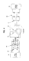
- FIGs. 4 to 8 are circuit diagrams illustrating various operation states of a driving apparatus for an electric vehicle according to a first embodiment of the present invention.
- the driving apparatus for the electric vehicle may separately operate the first battery 191 and the second battery 192 to operate in the motoring mode and the generating mode.
- the first inverter 160 connected to the first battery 191 may drive the motor 120 in the motoring mode upon engine startup (cranking) or upon engine driving, thereby generating required torque.
- the first inverter 160 may charge the first battery 191.
- the second inverter 170 connected to the second battery 192 may serve to assist required torque upon engine startup.
- the second inverter 170 charges the second battery 192.
- the motor controller 150 may individually control and operate the first inverter 160 and the second inverter 170.
- the number of switch elements 161 of the first inverter 160 may be equal to or greater than the number of switch elements 171 of the second inverter 170. In one embodiment, when the number of switch elements 161 of the first inverter 160 is 12, the number of switch elements 171 of the second inverter 170 may be 6. In particular, the first inverter 160 may have a structure in which a pair of switch elements 161 is connected in parallel.
- FIG. 4 shows an operation state in which the motoring mode of the motor 120 is implemented by the first inverter 160 alone.
- the motor controller 150 may generate required torque via the first battery 191 and the first inverter 160 upon engine driving.
- required torque may be received from the controller of the electric vehicle.
- the motor controller 150 may generate required torque by the first inverter 191 alone.
- required torque output from the first inverter 191 may assist torque output from the engine.
- the rotor 140, the main winding 131 and the first inverter 160 may be referred to as a first motor portion and the rotor 140, the auxiliary winding 132 and the second inverter 170 may be referred to as a second motor portion.
- the first motor portion operates in the motoring mode and the second motor portion is stopped.
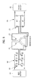
- FIG. 5 shows an operation state in which the motoring mode is implemented upon engine startup.
- the motor controller 150 may generate maximum torque via the first battery 191, the first inverter 160, the second battery 192 and the second inverter 170 upon engine startup.
- a cranking signal may be received from the controller of the electric vehicle.
- both the first inverter 160 and the second inverter 170 may operate in the motoring mode to generate maximum torque.
- total output torque may be 50 Nm.
- the output torque ratio of the first motor portion and the second motor portion may be determined according to the turn ratio of the main winding 131 to the auxiliary winding 132, as described above.
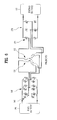
- FIG. 6 shows an operation state in which the motoring mode and the generating mode are simultaneously implemented.
- the motor controller 150 may generate required torque via the first battery 191 and the first inverter 160 and charge the second battery 192 via the second inverter 170, when the engine 110 is driven.
- required assist torque may be received from the controller of the electric vehicle while the electric vehicle is driven.
- the second battery 192 may need to be continuously charged.
- the motor controller 150 may control the first inverter 160 and the second inverter 170 such that the first motor portion performs the motoring operation and the second motor portion performs the generating operation.
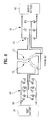
- FIG. 7 shows an operation state in which the first battery 191 and the second battery 192 are simultaneously charged.
- the motor controller 150 may charge the first battery 191 and the second battery 192 via the first inverter 160 and the second inverter 170, when the engine is driven. In other words, the motor controller 150 may charge the first battery 191 via the first inverter 160 and charge the second battery 192 via the second inverter 170, when the engine is driven.
- both the first and second inverters 160 and 170 may operate in the generating mode to charge the batteries 160 and 170.
- the motor controller 150 may vector-control the inverters 160 and 170 so as to generate negative torque in the regenerating mode.
- FIG. 8 shows an operation state in which the second battery 192 is charged with the charging voltage of the first battery 191 in a state in which the engine is stopped.
- the motor controller 150 may charge the second battery 192 via the first inverter 160 and the second inverter 170 with the charging voltage of the first battery 191 and the motor 120 may operate as a transformer according to the turn ratio of the main winding 131 to the auxiliary winding 132, when the engine 110 is stopped.
- the field winding 141, the main winding 131 and the auxiliary winding 132 operate as the transformer to change the charging voltage of the first battery 191 via the first inverter 160 and the second inverter 170, thereby charging the second battery 192.
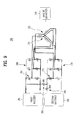
- FIGs. 9 to 12 are diagrams illustrating various operation states of a driving apparatus for an electric vehicle according to a second embodiment of the present invention.
- the charging apparatus 200 for the electric vehicle according to the second embodiment is different from the charging apparatus 100 for the electric vehicle according to the first embodiment as follows.
- the number of switching elements 261 of the first inverter 260 is equal to the number of switching elements 271 of the second inverter 270.
- first inverter 260 and the second inverter 270 are electrically connected.
- a first switch 293 may be provided between the first inverter 260 and the second inverter 270 and a second switch 294 may be provided between the second inverter 270 and the second battery 292.
- the first inverter 160 and the second inverter 170 are electrically disconnected. More specifically, the first inverter 160 and the second inverter 170 individually operate in a state of being electrically disconnected from each other, except the case in which the motor 120 is used as a transformer.
- the first inverter 260 and the second inverter 270 may be electrically connected and the switching element 271 of the second inverter 270 may be shared in a specific operation mode.
- the main winding 231, the first inverter 260 and the first battery 291 are electrically connected and the auxiliary winding 232, the second inverter 270 and the second battery 292 are electrically connected.
- FIG. 9 shows an operation state in which the motoring mode is implemented via the charging voltage of the first battery 291.
- the motor controller may turn the first switch 293 on and turn the second switch 294 off, thereby generating required torque via the charging voltage of the first battery 291.
- the switch elements 261 and 271 of the first inverter 260 and the second inverter 270 are shared through power of the first battery 291, thereby generating required torque.
- the switch elements 261 and 271 of the first and second inverters 260 and 270 are shared, thereby generating cranking torque when the engine 210 starts up via a total of 12 switch elements.
- required torque may be received from the controller of the electric vehicle.
- the motor controller may generate required torque using only the charging voltage of the first battery 291.
- the required torque may assist torque output from the engine.
- the first motor portion operates in the motoring mode and the second motor portion does not operate in the motoring mode and the switching element is only shared.
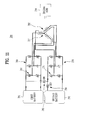
- FIG. 10 shows an operation state in which the motoring mode and the generating mode are simultaneously implemented.
- the motor controller may turn the first switch 293 off and turn the second switch 294 on when the engine is driven, thereby generating required torque via the first battery 291 and the first inverter 260 and charging the second battery 292 via the second inverter 270.
- the first switch 293 By turning the first switch 293 off, the first inverter 260 and the second inverter 270 are electrically disconnected so as to independently operate.
- required assist torque may be received from the controller of the electric vehicle.
- the motor controller may control the first inverter 260 and the second inverter 270 such that the first motor portion operates in the motoring mode and the second motor portion operates in the generating mode.
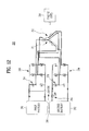
- FIG. 11 shows an operation state in which the first battery 291 and the second battery 292 are simultaneously charged.
- the motor controller may charge the first battery 291 and the second battery 292 via the first inverter 260 and the second inverter 270, when the engine 210 is driven.
- the motor controller turns the first switch 293 off and turns the second switch 294 on. That is, by turning the first switch 293 off, the first inverter 260 and the second inverter 270 are electrically disconnected to independently operate.
- the first and second inverters 260 and 270 operate as generators to charge the batteries 291 and 292.
- the motor controller may vector-control the inverters 260 and 270 so as to generate negative torque in the regenerating mode.
- FIG. 12 shows an operation state in which the second battery 292 is charged with the charging voltage of the first battery 291 in a state in which the engine 210 is stopped.
- the motor controller may charge the second battery 292 via the first inverter 260 and the second inverter 270 with the charging voltage of the first battery 191 and the motor may operate as a transformer according to the turn ratio of the main winding 231 to the auxiliary winding 232, when the engine 110 is stopped.
- the motor controller turns the first switch 293 off and turns the second switch 294 on. That is, by turning the first switch 293 off, the first inverter 260 and the second inverter 270 are electrically disconnected to independently operate.
- the field winding, the main winding 231 and the auxiliary winding 232 operate as the transformer to change the charging voltage of the first battery 291 via the first inverter 260 and the second inverter2170, thereby charging the second battery 292.
- FIG. 13 is a diagram showing the concept of a field current controller 180 of a driving apparatus for an electric vehicle according to one embodiment of the present invention.
- transformation is performed by the turn ratio. More specifically, when the second battery 192 is charged with the charging voltage of the first battery 191 in a state in which the engine and the rotor are stopped, a boosted voltage may be applied to the field winding 141.
- the circuit of the field current controller 180 needs to be protected and thus an interrupter switch may be provided between the field current controller 180 and the field winding 141.
- the interrupter switch may be a relay switch 182 or a high-voltage switch for circuit interruption 183.
- the rotor 140 may have a field winding but the present invention is not limited thereto.
- the rotor 140 may have a permanent magnet, instead of the field winding.
- the driving apparatus for the electric vehicle has the following effects.
Landscapes
- Engineering & Computer Science (AREA)
- Power Engineering (AREA)
- Transportation (AREA)
- Mechanical Engineering (AREA)
- Life Sciences & Earth Sciences (AREA)
- Sustainable Development (AREA)
- Sustainable Energy (AREA)
- Electric Propulsion And Braking For Vehicles (AREA)
Abstract
Description
- This application claims the benefit of Korean Patent Application No.
10-2013-0139312, filed on November 15, 2013 - The present invention relates to a driving apparatus for an electric vehicle.
- Recently, with increasingly stringent environmental regulations and to reduce energy costs, demand for eco-friendly electric vehicles (EVs) has increased. In the United States and Europe, electric vehicles will be forced into widespread use due to the Clean Air Conservation Act. Domestically, research into a green car has been actively conducted as a part of green growth.
- A battery is provided in an electric vehicle in order to drive a motor for driving the vehicle and various electronic apparatuses. In addition, an air conditioner for air conditioning or heating is provided.
- In addition, an integrated starter generator (ISG) for starting an engine and rotating a motor is provided in an electric vehicle. The ISG operates in a motoring mode for rotating the motor and a generating mode for generating a predetermined output voltage to charge a battery.
- A plurality of batteries having different charging voltages may be provided in the electric vehicle. At this time, each battery may be charged in the generating mode of the ISG.
- As the ISG is generally configured to generate a high output voltage, a high-voltage battery may be charged via the output voltage of the ISG but a low-voltage battery may not be charged via the output voltage of the ISG. Thus, a separate DC-DC converter is required.
- That is, the DC-DC converter performs a function for decreasing the high output voltage of the ISG to a charging voltage of the low-voltage battery.
- However, the DC-DC converter has a heavy weight and a large volume, thereby increasing the weight of the electric vehicle and reducing an internal space for use. In addition, the DC-DC converter may deteriorate efficiency of the electric vehicle.
- Accordingly, even when a plurality of batteries having different charging voltages is provided, there is a need for a structure for charging each battery via a single ISG without a separate DC-DC converter.
- In order to charge a high-voltage battery and a low-voltage battery using an ISG, rotation force of an engine should be delivered to the ISG. At this time, it is difficult to charge the high-voltage battery and the low-voltage battery using the ISG in a state in which the engine is not driven.
- Accordingly, there is a need for a structure for emergency-charging a low-voltage battery even in a state in which an engine is not driven.
- Accordingly, the present invention is directed to a driving apparatus for an electric vehicle that substantially obviates one or more problems due to limitations and disadvantages of the related art.
- An object of the present invention is to provide a driving apparatus for an electric vehicle capable of selectively charging a plurality of batteries having different charging voltages without using a separate DC-DC converter.
- Another object of the present invention is to provide a driving apparatus for an electric vehicle capable of outputting required torque upon engine startup or upon normal driving by using a charging voltage of any one of a high-voltage battery and a low-voltage battery or both the charging voltages of the high-voltage battery and the low-voltage battery.
- Another object of the present invention is to provide a driving apparatus for an electric vehicle capable of charging the other batteries using any one battery in a state in which an engine is stopped.
- Another object of the present invention is to provide a driving apparatus for an electric vehicle having a low weight and a small volume and capable of making better use of a space.
- Additional advantages, objects, and features of the invention will be set forth in part in the description which follows and in part will become apparent to those having ordinary skill in the art upon examination of the following or may be learned from practice of the invention. The objectives and other advantages of the invention may be realized and attained by the structure particularly pointed out in the written description and claims hereof as well as the appended drawings.
- To achieve these objects and other advantages and in accordance with the purpose of the invention, as embodied and broadly described herein, a driving apparatus for an electric vehicle including a motor including a stator having a main winding and an auxiliary winding and a rotor rotating due to magnetic interaction between the main winding and the auxiliary winding, an engine configured to selectively rotate the rotor, a motor controller including a first inverter connected to the main winding and a second inverter connected to the auxiliary winding, a first battery connected to the first inverter and configured to drive the motor or configured to be chargeable by the motor, and a second battery connected to the second inverter, configured to be chargeable by the motor, and having a charging voltage lower than that of the first battery.
- The motor controller may generate required torque via the charging voltage of at least one of the first battery and the second battery based on at least one of residual quantities of the first battery and the second battery and a driving state of the engine.
- The motor controller may charge at least one of the first battery and the second battery.
- The motor controller may generate required torque and, at the same time, charges any one battery.
- The motor controller may generate required torque via the first battery and the first inverter when the engine is driven.
- The motor controller may generate maximum torque via the first battery, the first inverter, the second battery and the second inverter.
- The motor controller may generate required torque via the first battery and the first inverter and charge the second battery via the second inverter, when the engine is driven.
- The motor controller may charge the first battery and the second battery via the first inverter and the second inverter, when the engine is driven.
- The motor controller may charge the second battery via the first inverter and the second inverter with the charging voltage of the first battery, when the engine is stopped, and the motor may operate as a transformer according to a turn ratio of the main winding to the auxiliary winding.
- The auxiliary winding may be wound using a hairpin winding method, and the auxiliary winding may be located closer to the rotor than the main winding.
- The number of switch elements of the first inverter may be equal to or greater than the number of switch elements of the second inverter, the first inverter and the second inverter may be electrically connected, a first switch for connecting an output end of the first battery and an output end of the second battery may be provided, and a second switch may be provided between the first switch and the second battery.
- The motor controller may turn the first switch on and turn the second switch off to generate required torque via the first battery, the first inverter and the second inverter.
- When the engine is driven, the motor controller may turn the first switch off and turn the second switch on to generate required torque via the first battery and the first inverter and to charge the second battery via the second inverter.
- When the engine is driven, the motor controller may turn the first switch off and turn the second switch on to charge the first battery via the first inverter and to charge the second battery via the second inverter.
- When the engine is stopped, the motor controller may turn the first switch off and turn the second switch on to charge the second battery via the first inverter and the second inverter with the charging voltage of the first battery, and the motor may operate as a transformer according to a turn ratio of the main winding to the auxiliary winding.
- In addition, the main winding and the auxiliary winding may be wound using a distributed winding method or a centralized winding method.
- The turn ratio of the main winding to the auxiliary winding may be 2:1 or 5:1.
- The rotor may have a field winding.
- The motor controller may further include a field current controller connected to the field winding.
- The motor controller may vector-control the first inverter and the second inverter to generate negative torque in a regenerating mode.
- It is to be understood that both the foregoing general description and the following detailed description of the present invention are exemplary and explanatory and are intended to provide further explanation of the invention as claimed.
- The accompanying drawings, which are included to provide a further understanding of the invention and are incorporated in and constitute a part of this application, illustrate embodiment(s) of the invention and together with the description serve to explain the principle of the invention. In the drawings:
-
FIGs. 1 and2 are diagrams showing the concepts of a driving apparatus for an electric vehicle according to one embodiment of the present invention; -
FIG. 3 is a diagram showing the concept of various embodiments of a main winding and an auxiliary winding of a stator according to the present invention; -
FIGs. 4 to 8 are circuit diagrams illustrating various operation states of a driving apparatus for an electric vehicle according to a first embodiment of the present invention; -
FIGs. 9 to 12 are diagrams illustrating various operation states of a driving apparatus for an electric vehicle according to a second embodiment of the present invention; -
FIG. 13 is a diagram showing the concept of a field current controller of a driving apparatus for an electric vehicle according to one embodiment of the present invention. - Hereinafter, a driving apparatus for an electric vehicle (hereinafter, also referred to as a driving apparatus) according to one embodiment of the present invention will be described in detail with reference to the accompanying drawings. The accompanying drawings are only provided for describing the present invention in detail and are not intended to limit the technical range of the present invention.
- In addition, the same or corresponding components are designated by the same reference numerals, and a description thereof will not be repeated. For convenience of description, the size and shape of each component may be exaggerated or reduced.
-
FIGs. 1 and2 are diagrams showing the concepts of adriving apparatus 100 for an electric vehicle according to one embodiment of the present invention. - Referring to
FIG. 1 , thedriving apparatus 100 according to one embodiment of the present invention includes amotor 120, anengine 110, afirst battery 191, asecond battery 192 and amotor controller 150. - Here, the
second battery 192 and thefirst battery 191 have different charging voltages. The charging voltage of thesecond battery 192 is lower than that of thefirst battery 191. In one embodiment, thefirst battery 191 may have a charging voltage of 43 V or 48V and thesecond battery 192 may have a charging voltage of 12 V. - In addition, the
first battery 191 may be referred to as a high-voltage battery and thesecond battery 192 may be referred to as a low-voltage battery. In addition, thefirst battery 191 may have a maximum charging voltage of 60 V and thesecond battery 192 may have a maximum charging voltage of 24 V in case of a full-size car. - The
motor 120 may include astator 130 and arotor 140. In addition, themotor 120 may include astator 130 having a main winding 131 and an auxiliary winding 132 and arotor 140 rotating due to magnetic interaction between the main winding 131 and the auxiliary winding 132. Therotor 140 rotates in thestator 130 via electromagnetic interaction with thestator 130. - The
stator 130 may include armature coils 131 and 132 in order to form a magnetic flux. Accordingly, thestator 130 may be referred to as an electromagnet. - The
rotor 140 may rotate within thestator 130. Therotor 140 may include a field winding 141. Here, themotor controller 150 may control the output of therotor 140 by adjusting the field current value and the armature current value respectively applied to the field winding 141 and the armature coils 131 and 132. - More specifically, field current may be applied to the field winding 141 and armature current may be applied to the armature coils 131 and 132. The output of the
rotor 140 may be determined according to the field current value and the armature current value. - In addition, the
motor 120 includes therotor 140 having the field winding 141 formed by winding a field coil. In addition, themotor 120 includes thestator 130 having thearmature windings motor 120 may be a field winding motor. - The main winding 131 and the auxiliary winding 132 are provided in the
stator 130. In addition, the armature winding may have a dual structure. More specifically, thestator 130 has a dual winding structure. The dual winding structure of thestator 130 will be described below. - In addition, the
stator 130 includes the main winding 131 and the auxiliary winding 132. Two motors having different output voltages may be unified by connecting individual inverters to thewindings stator 130. - The driving
apparatus 100 includes afirst inverter 160 and asecond inverter 170 electrically connected to thestator 130 of themotor 120. - The
first inverter 160 is connected to the main winding 131 of thestator 130 and thesecond inverter 170 is connected to the auxiliary winding 132 of thestator 130. At this time, thefirst inverter 160 may be referred to as a main inverter and thesecond inverter 170 may be referred to as an auxiliary inverter. - The
first inverter 160 is electrically connected to thefirst battery 191. In addition, thesecond inverter 170 is electrically connected to thesecond battery 192. - The driving
apparatus 100 may include the fieldcurrent controller 180 electrically connected to therotor 140 of themotor 120. Themotor controller 150 may include the fieldcurrent controller 180 connected to the field winding 141. More specifically, the fieldcurrent controller 180 is electrically connected to the field winding 141 of therotor 140. - The
motor 120 may operate in a motoring mode such as engine startup or torque assist and a generating mode for generating a predetermined output voltage. - The generating mode may include a normal generating mode and a regenerating mode. Accordingly, the
motor 120 may be referred to as a driving motor for an electric vehicle or an integrated starter generator (ISG). - At this time, in the generating mode, the
motor 120 may selectively charge thefirst battery 191 and thesecond battery 192 using the output voltage. Themotor 120 may simultaneously charge thefirst battery 191 and thesecond battery 192 using the output voltage. - In addition, the
motor 120 may rotate by driving theengine 110, thereby operating in the generating mode. In addition, themotor 120 may operate in the generating mode even in a state in which theengine 110 is stopped, which will be described below. - The
engine 110 rotates the motor. More specifically, theengine 110 selectively rotates therotor 140. A clutch (not shown) for delivering rotation force of the engine to therotor 140 may be selectively provided between theengine 110 and themotor 120. The clutch may be an electronic clutch. - The
first battery 191 may drive themotor 120 via a charging voltage. In addition, thefirst battery 191 may be charged by themotor 120. Thefirst battery 191 may drive the motor alone via the charging voltage in the motoring mode. - More specifically, the voltage charged in the
first battery 191 is supplied to the main winding 131 of thestator 130 via thefirst inverter 160. In addition, in the generating mode, thefirst battery 191 may be charged via thefirst inverter 160. - The
second battery 192 may be charged by themotor 120. In addition, thesecond battery 192 may drive themotor 120 via the charging voltage. - The
second battery 192 may not drive themotor 120 alone but may drive themotor 120 together with thefirst battery 191. That is, the charging voltage of thesecond battery 192 may serve to assist torque of a predetermined portion in the motoring mode via the charging voltage of thefirst battery 191. - The
motor controller 150 may charge at least one of thefirst battery 191 and thesecond battery 192. - More specifically, the
motor controller 150 may selectively charge thefirst battery 191 or thesecond battery 192 based on at least one of the residual quantities of thefirst battery 191 and thesecond battery 192 and the driving state of theengine 110. Themotor controller 150 may selectively charge thefirst battery 191 or thesecond battery 192 by adjusting the field current value applied to the field winding 141. - The
motor controller 150 may generate required torque via the charging voltage of at least one of thefirst battery 191 and thesecond battery 192 based on at least one of the residual quantities of thefirst battery 191 and thesecond battery 192 and the driving state of theengine 110. - More specifically, the
motor controller 150 may generate required torque by utilizing the charging voltage of thefirst battery 191 alone. In addition, themotor controller 150 may generate required torque by utilizing both the charging voltages of thefirst battery 191 and thesecond battery 192. - In summary, the
motor controller 150 may generate required torque via the charging voltage of at least one of thefirst battery 191 and thesecond battery 192, or charge at least one of thefirst battery 191 and thesecond battery 192 or generate required torque via thefirst battery 191 and, at the same time, charge thesecond battery 192, based on at least one of the residual quantities of thefirst battery 191 and thesecond battery 192 and the driving state of theengine 110. - The
motor controller 150 may generate different output voltages via thefirst inverter 160 and thesecond inverter 170 without a separate DC-DC converter. - In the
motor controller 150, the output voltage of thestator 130 and the field current value corresponding to the output voltage of thestator 130 may be stored. More specifically, in themotor controller 150, the output voltage of thestator 130 and the field current value corresponding to the output voltage of thestator 130 may be stored in the form of a look-up table. - The
motor controller 150 may include thefirst inverter 160 connected to the main winding 131 and thesecond inverter 170 connected to the auxiliary winding 132. Themotor controller 150 may include the fieldcurrent controller 180 connected to the field winding 141. - The driving state of the
engine 110 may include an on/off state of the engine and a revolutions per minute (RPM) of the engine. - The
motor controller 150 may be provided integrally with themotor 120. More specifically, themotor 120, the first andsecond inverters current controller 180 may be integrally provided. In this case, an internal space of the electric vehicle is secured. - In addition, the
motor controller 150 may be cooled via cooling water for cooling themotor 120. Accordingly, cooling efficiency of themotor controller 150 may be increased. - Alternatively, only the first and
second inverters current controller 180 may be integrally provided. Themotor controller 150 may be provided in the electric vehicle to be separated from themotor 120. In this case, themotor controller 150 and themotor 120 may be electrically connected via a cable. -
FIG. 3 is a diagram showing the concept of various embodiments of a main winding 131 (131a, 131b and 131c) and an auxiliary winding 132 (132a, 132b and 132c) of a stator according to the present invention. - The main winding 131 and the auxiliary winding 132 may be wound using a distributed winding method or a centralized winding method. The main winding 131 and the auxiliary winding 132 may be wound using a hairpin winding method. The main winding 131 and the auxiliary winding 132 may be wound using the distributed winding method, the centralized winding method or the hairpin winding method.
- Referring to
FIG. 3 (a) , the main winding 131 a may be wound using the hairpin winding method and the auxiliary winding 132a may be wound using the distributed winding method. At this time, the main winding 131a may be located closer to the center of the stator than the auxiliary winding 132a. - Referring to
FIG. 3(b) , the main winding 131b may be wound using the hairpin winding method and the auxiliary winding 132b may be wound using the distributed winding method. At this time, the auxiliary winding 132b may be located closer to the center of the stator than the main winding 131b. - Referring to
FIG. 3(c) , the main winding 131 c may be wound using the hairpin winding method and the auxiliary winding 132c may be wound using the hairpin winding method. At this time, the auxiliary winding 132c may be located closer to the center of the stator than the main winding 131 c. More specifically, the auxiliary winding 132c may be located closer to the rotor than the main winding 131 c. That is, a distance between the auxiliary winding 132c and the rotor may be less than a distance between the main winding 131 c and the rotor. - If workability and motor efficiency are considered, the main winding 131 and the auxiliary winding 132 may be wound using the hairpin winding method. For torque efficiency, the auxiliary winding 132 may be located closer to the center of the stator than the main winding 131.
- The turn ratio of the main winding 131 to the auxiliary winding 132 may be 2:1 or 5:1. In one embodiment, the turn ratio of the main winding 131 to the auxiliary winding 132 may be 4:1. The turn ratio may be variously determined according to capacity of the
first battery 191 and thesecond battery 192 and the required torque of themotor 120. -
FIGs. 4 to 8 are circuit diagrams illustrating various operation states of a driving apparatus for an electric vehicle according to a first embodiment of the present invention. - In particular, the driving apparatus for the electric vehicle according to the first embodiment may separately operate the
first battery 191 and thesecond battery 192 to operate in the motoring mode and the generating mode. - More specifically, the
first inverter 160 connected to thefirst battery 191 may drive themotor 120 in the motoring mode upon engine startup (cranking) or upon engine driving, thereby generating required torque. In addition, in the generating mode, thefirst inverter 160 may charge thefirst battery 191. - The
second inverter 170 connected to thesecond battery 192 may serve to assist required torque upon engine startup. In addition, in the generating mode, thesecond inverter 170 charges thesecond battery 192. Themotor controller 150 may individually control and operate thefirst inverter 160 and thesecond inverter 170. - The number of
switch elements 161 of thefirst inverter 160 may be equal to or greater than the number ofswitch elements 171 of thesecond inverter 170. In one embodiment, when the number ofswitch elements 161 of thefirst inverter 160 is 12, the number ofswitch elements 171 of thesecond inverter 170 may be 6. In particular, thefirst inverter 160 may have a structure in which a pair ofswitch elements 161 is connected in parallel. -
FIG. 4 shows an operation state in which the motoring mode of themotor 120 is implemented by thefirst inverter 160 alone. - Referring to
FIG. 4 , themotor controller 150 may generate required torque via thefirst battery 191 and thefirst inverter 160 upon engine driving. - More specifically, when the electric motor needs to accelerate, required torque may be received from the controller of the electric vehicle. At this time, when it is determined that the
second battery 192 does not need to be charged, themotor controller 150 may generate required torque by thefirst inverter 191 alone. In addition, required torque output from thefirst inverter 191 may assist torque output from the engine. - The
rotor 140, the main winding 131 and thefirst inverter 160 may be referred to as a first motor portion and therotor 140, the auxiliary winding 132 and thesecond inverter 170 may be referred to as a second motor portion. Referring toFIG. 4 , the first motor portion operates in the motoring mode and the second motor portion is stopped. -
FIG. 5 shows an operation state in which the motoring mode is implemented upon engine startup. - Referring to
FIG. 5 , themotor controller 150 may generate maximum torque via thefirst battery 191, thefirst inverter 160, thesecond battery 192 and thesecond inverter 170 upon engine startup. - More specifically, in a state in which the
engine 110 is stopped, a cranking signal may be received from the controller of the electric vehicle. At this time, both thefirst inverter 160 and thesecond inverter 170 may operate in the motoring mode to generate maximum torque. - In one embodiment, when the first motor portion generates torque of 40 Nm and the second motor portion generates torque of 10 Nm, total output torque may be 50 Nm. The output torque ratio of the first motor portion and the second motor portion may be determined according to the turn ratio of the main winding 131 to the auxiliary winding 132, as described above.
-
FIG. 6 shows an operation state in which the motoring mode and the generating mode are simultaneously implemented. - The
motor controller 150 may generate required torque via thefirst battery 191 and thefirst inverter 160 and charge thesecond battery 192 via thesecond inverter 170, when theengine 110 is driven. - More specifically, required assist torque may be received from the controller of the electric vehicle while the electric vehicle is driven. At this time, the
second battery 192 may need to be continuously charged. Themotor controller 150 may control thefirst inverter 160 and thesecond inverter 170 such that the first motor portion performs the motoring operation and the second motor portion performs the generating operation. -
FIG. 7 shows an operation state in which thefirst battery 191 and thesecond battery 192 are simultaneously charged. - The
motor controller 150 may charge thefirst battery 191 and thesecond battery 192 via thefirst inverter 160 and thesecond inverter 170, when the engine is driven. In other words, themotor controller 150 may charge thefirst battery 191 via thefirst inverter 160 and charge thesecond battery 192 via thesecond inverter 170, when the engine is driven. - More specifically, when the electric vehicle is stopped or decelerated, both the first and
second inverters batteries motor controller 150 may vector-control theinverters -
FIG. 8 shows an operation state in which thesecond battery 192 is charged with the charging voltage of thefirst battery 191 in a state in which the engine is stopped. - The
motor controller 150 may charge thesecond battery 192 via thefirst inverter 160 and thesecond inverter 170 with the charging voltage of thefirst battery 191 and themotor 120 may operate as a transformer according to the turn ratio of the main winding 131 to the auxiliary winding 132, when theengine 110 is stopped. - More specifically, the field winding 141, the main winding 131 and the auxiliary winding 132 operate as the transformer to change the charging voltage of the
first battery 191 via thefirst inverter 160 and thesecond inverter 170, thereby charging thesecond battery 192. -
FIGs. 9 to 12 are diagrams illustrating various operation states of a driving apparatus for an electric vehicle according to a second embodiment of the present invention. - The charging
apparatus 200 for the electric vehicle according to the second embodiment is different from the chargingapparatus 100 for the electric vehicle according to the first embodiment as follows. - In the
charging apparatus 200 according to the second embodiment, the number of switchingelements 261 of thefirst inverter 260 is equal to the number of switchingelements 271 of thesecond inverter 270. - In addition, the
first inverter 260 and thesecond inverter 270 are electrically connected. In addition, afirst switch 293 may be provided between thefirst inverter 260 and thesecond inverter 270 and asecond switch 294 may be provided between thesecond inverter 270 and thesecond battery 292. - In the first embodiment, the
first inverter 160 and thesecond inverter 170 are electrically disconnected. More specifically, thefirst inverter 160 and thesecond inverter 170 individually operate in a state of being electrically disconnected from each other, except the case in which themotor 120 is used as a transformer. - However, in the second embodiment, the
first inverter 260 and thesecond inverter 270 may be electrically connected and theswitching element 271 of thesecond inverter 270 may be shared in a specific operation mode. - Even in the second embodiment, similarly to the first embodiment, the main winding 231, the
first inverter 260 and thefirst battery 291 are electrically connected and the auxiliary winding 232, thesecond inverter 270 and thesecond battery 292 are electrically connected. -
FIG. 9 shows an operation state in which the motoring mode is implemented via the charging voltage of thefirst battery 291. - The motor controller may turn the
first switch 293 on and turn thesecond switch 294 off, thereby generating required torque via the charging voltage of thefirst battery 291. - At this time, the
switch elements first inverter 260 and thesecond inverter 270 are shared through power of thefirst battery 291, thereby generating required torque. - In one embodiment, the
switch elements second inverters engine 210 starts up via a total of 12 switch elements. - In addition, when the electric vehicle needs to be accelerated while the
engine 210 is driven, required torque may be received from the controller of the electric vehicle. - At this time, when the
second battery 292 does not need to be charged, the motor controller may generate required torque using only the charging voltage of thefirst battery 291. In addition, the required torque may assist torque output from the engine. - In this case, the first motor portion operates in the motoring mode and the second motor portion does not operate in the motoring mode and the switching element is only shared.
-
FIG. 10 shows an operation state in which the motoring mode and the generating mode are simultaneously implemented. - The motor controller may turn the
first switch 293 off and turn thesecond switch 294 on when the engine is driven, thereby generating required torque via thefirst battery 291 and thefirst inverter 260 and charging thesecond battery 292 via thesecond inverter 270. - By turning the
first switch 293 off, thefirst inverter 260 and thesecond inverter 270 are electrically disconnected so as to independently operate. - More specifically, while the electric vehicle is driven, required assist torque may be received from the controller of the electric vehicle.
- At this time, the second battery may need to be continuously charged. The motor controller may control the
first inverter 260 and thesecond inverter 270 such that the first motor portion operates in the motoring mode and the second motor portion operates in the generating mode. -
FIG. 11 shows an operation state in which thefirst battery 291 and thesecond battery 292 are simultaneously charged. - The motor controller may charge the
first battery 291 and thesecond battery 292 via thefirst inverter 260 and thesecond inverter 270, when theengine 210 is driven. - At this time, the motor controller turns the
first switch 293 off and turns thesecond switch 294 on. That is, by turning thefirst switch 293 off, thefirst inverter 260 and thesecond inverter 270 are electrically disconnected to independently operate. - More specifically, when the electric vehicle is stopped or decelerated, the first and
second inverters batteries inverters -
FIG. 12 shows an operation state in which thesecond battery 292 is charged with the charging voltage of thefirst battery 291 in a state in which theengine 210 is stopped. - The motor controller may charge the
second battery 292 via thefirst inverter 260 and thesecond inverter 270 with the charging voltage of thefirst battery 191 and the motor may operate as a transformer according to the turn ratio of the main winding 231 to the auxiliary winding 232, when theengine 110 is stopped. - At this time, the motor controller turns the
first switch 293 off and turns thesecond switch 294 on. That is, by turning thefirst switch 293 off, thefirst inverter 260 and thesecond inverter 270 are electrically disconnected to independently operate. - More specifically, the field winding, the main winding 231 and the auxiliary winding 232 operate as the transformer to change the charging voltage of the
first battery 291 via thefirst inverter 260 and the second inverter2170, thereby charging thesecond battery 292. -
FIG. 13 is a diagram showing the concept of a fieldcurrent controller 180 of a driving apparatus for an electric vehicle according to one embodiment of the present invention. - When the
second battery 192 is charged with the charging voltage of thefirst battery 191 in a state in which the engine is stopped, transformation is performed by the turn ratio. More specifically, when thesecond battery 192 is charged with the charging voltage of thefirst battery 191 in a state in which the engine and the rotor are stopped, a boosted voltage may be applied to the field winding 141. - Accordingly, the circuit of the field
current controller 180 needs to be protected and thus an interrupter switch may be provided between the fieldcurrent controller 180 and the field winding 141. - The interrupter switch may be a
relay switch 182 or a high-voltage switch forcircuit interruption 183. - The
rotor 140 may have a field winding but the present invention is not limited thereto. For example, therotor 140 may have a permanent magnet, instead of the field winding. - As described above, the driving apparatus for the electric vehicle according to one embodiment of the present invention has the following effects.
- It is possible to output different required torque upon engine startup or upon normal driving, by utilizing any one or both of charging voltages of a high-voltage battery and a low-voltage battery.
- It is possible to selectively charge a plurality of batteries having different charging voltages without using a separate converter.
- In addition, it is possible to charge the other batteries using any one battery in a state in which an engine is stopped.
- It will be apparent to those skilled in the art that various modifications and variations can be made in the present invention without departing from the spirit or scope of the inventions. Thus, it is intended that the present invention covers the modifications and variations of this invention provided they come within the scope of the appended claims and their equivalents.
Claims (15)
- A driving apparatus for an electric vehicle, comprising:a motor (120) including a stator (130) having a main winding (131) and an auxiliary winding (132) and a rotor (140) rotating due to magnetic interaction between the main winding (131) and the auxiliary winding (132);an engine (110) configured to selectively rotate the rotor (140);a motor controller (150) including a first inverter (160) connected to the main winding (131) and a second inverter (170) connected to the auxiliary winding (132);a first battery (191) connected to the first inverter (160) and configured to drive the motor (120) or configured to be chargeable by the motor (120); anda second battery (192) connected to the second inverter (170), configured to be chargeable by the motor (120), and having a charging voltage lower than that of the first battery (191).
- The driving apparatus for the electric vehicle according to claim 1, wherein the motor controller (150) generates required torque via the charging voltage of at least one of the first battery (191) and the second battery (192) based on at least one of residual quantities of the first battery (191) and the second battery (192) and a driving state of the engine (110).
- The driving apparatus for the electric vehicle according to claims 1 or 2, wherein the motor controller (150) charges at least one of the first battery (191) and the second battery (192).
- The driving apparatus for the electric vehicle according to any one of claims 1 to 3, wherein the motor controller (150) generates required torque and, at the same time, charges any one battery.
- The driving apparatus for the electric vehicle according to any one of claims 1 to 4, wherein the motor controller (150) generates required torque via the first battery (191) and the first inverter (160) when the engine (110) is driven.
- The driving apparatus for the electric vehicle according to any one of claims 1 to 5, wherein the motor controller (150) generates maximum torque via the first battery (191), the first inverter (160), the second battery (192) and the second inverter (170).
- The driving apparatus for the electric vehicle according to any one of claims 1 to 6, wherein the motor controller (150) generates required torque via the first battery (191) and the first inverter (160) and charges the second battery (192) via the second inverter (170), when the engine (110) is driven.
- The driving apparatus for the electric vehicle according to any one of claims 1 to 7, wherein the motor controller (150) charges the first battery (191) and the second battery (192) via the first inverter (160) and the second inverter (170), when the engine (110) is driven.
- The driving apparatus for the electric vehicle according to any one of claims 1 to 8, wherein:the motor controller (150) charges the second battery (192) via the first inverter (160) and the second inverter (170) with the charging voltage of the first battery (191), when the engine (110) is stopped, andthe motor (120) operates as a transformer according to a turn ratio of the main winding (131) to the auxiliary winding (132).
- The driving apparatus for the electric vehicle according to any one of claims 1 to 9, wherein:the auxiliary winding (132) is wound using a hairpin winding method, andthe auxiliary winding (132) is located closer to the rotor than the main winding (131).
- The driving apparatus for the electric vehicle according to any one of claims 1 to 10, wherein:the number of switch elements (261) of the first inverter (260) is equal to or greater than the number of switch elements (271) of the second inverter (270),the first inverter (260) and the second inverter (270) are electrically connected,a first switch (293) for connecting an output end of the first battery (291) and an output end of the second battery (292) is provided, anda second switch (294) is provided between the first switch (293) and the second battery (292).
- The driving apparatus for the electric vehicle according to claim 11, wherein the motor controller (150) turns the first switch (293) on and turns the second switch (294) off to generate required torque via the first battery (291), the first inverter (260) and the second inverter (270).
- The driving apparatus for the electric vehicle according to claims 11 or 12, wherein, when the engine (210) is driven, the motor controller (150) turns the first switch (293) off and turns the second switch (294) on to generate required torque via the first battery (291) and the first inverter (260) and to charge the second battery (292) via the second inverter (270).
- The driving apparatus for the electric vehicle according to any one of claims 11 to 13, wherein, when the engine (210) is driven, the motor controller turns the first switch (293) off and turns the second switch (294) on to charge the first battery (291) via the first inverter (260) and to charge the second battery (292) via the second inverter (270).
- The driving apparatus for the electric vehicle according to any one of claims 11 to 14, wherein:when the engine (210) is stopped, the motor controller turns the first switch (293) off and turns the second switch (294) on to charge the second battery (292) via the first inverter (260) and the second inverter (270) with the charging voltage of the first battery (291), andthe motor (120) operates as a transformer according to a turn ratio of the main winding (231) to the auxiliary winding (232).
Applications Claiming Priority (1)
| Application Number | Priority Date | Filing Date | Title |
|---|---|---|---|
| KR1020130139312A KR101549026B1 (en) | 2013-11-15 | 2013-11-15 | Driving apparatus for electric vehicle |
Publications (3)
| Publication Number | Publication Date |
|---|---|
| EP2873551A2 true EP2873551A2 (en) | 2015-05-20 |
| EP2873551A3 EP2873551A3 (en) | 2015-07-22 |
| EP2873551B1 EP2873551B1 (en) | 2021-01-13 |
Family
ID=50396889
Family Applications (1)
| Application Number | Title | Priority Date | Filing Date |
|---|---|---|---|
| EP14161775.3A Active EP2873551B1 (en) | 2013-11-15 | 2014-03-26 | Driving apparatus for electric vehicle |
Country Status (3)
| Country | Link |
|---|---|
| EP (1) | EP2873551B1 (en) |
| KR (1) | KR101549026B1 (en) |
| CN (1) | CN104648173B (en) |
Cited By (8)
| Publication number | Priority date | Publication date | Assignee | Title |
|---|---|---|---|---|
| US9742225B2 (en) | 2015-08-11 | 2017-08-22 | Genesis Robotics Llp | Electric machine |
| CN107979321A (en) * | 2017-12-27 | 2018-05-01 | 南京航空航天大学 | It is multiplexed the electric excitation biconvex electrode electric machine driving charging integration system of Exciting Windings for Transverse Differential Protection |
| WO2018077549A1 (en) * | 2016-10-27 | 2018-05-03 | Pierburg Gmbh | Drive system for an electrically driven motor vehicle |
| EP3594046A1 (en) * | 2018-07-11 | 2020-01-15 | Sungrow Power Supply Co., Ltd. | Power system of electric vehicle,control method and electric vehicle |
| US11043885B2 (en) | 2016-07-15 | 2021-06-22 | Genesis Robotics And Motion Technologies Canada, Ulc | Rotary actuator |
| US11139707B2 (en) | 2015-08-11 | 2021-10-05 | Genesis Robotics And Motion Technologies Canada, Ulc | Axial gap electric machine with permanent magnets arranged between posts |
| CN114368290A (en) * | 2021-12-08 | 2022-04-19 | 奇瑞商用车(安徽)有限公司 | Electric vehicle drive control method and device, electric vehicle and storage medium |
| US20250388127A1 (en) * | 2024-06-20 | 2025-12-25 | Hyundai Motor Company | Method for controlling a battery for an electric vehicle, a controller, and an electric vehicle |
Families Citing this family (7)
| Publication number | Priority date | Publication date | Assignee | Title |
|---|---|---|---|---|
| KR101692635B1 (en) | 2015-08-31 | 2017-01-03 | 쌍용자동차 주식회사 | Rights field with a linear synchronous motor in electric vehicle battery charge control apparatus and method |
| CN106451676A (en) * | 2016-11-29 | 2017-02-22 | 南京九致信息科技有限公司 | Vehicular charging system for electric tool |
| CN107472064A (en) * | 2017-08-10 | 2017-12-15 | 杭州衡源汽车科技有限公司 | A kind of drive control method, apparatus and electric automobile |
| KR101954950B1 (en) | 2018-06-05 | 2019-03-06 | 주식회사 코터스 | Battery charging system for electric bicycle |
| GB2584157B (en) * | 2019-05-24 | 2024-04-03 | Zf Automotive Uk Ltd | Improvements relating to multi-lane motor circuits |
| KR102800727B1 (en) * | 2022-09-19 | 2025-04-25 | 주식회사 현대케피코 | Battery Swapping System and Method for Electric Vehicle |
| US12237742B2 (en) | 2022-12-20 | 2025-02-25 | Hl Mando Corporation | Electric motor having hairpin type windings and method for designing the same |
Family Cites Families (12)
| Publication number | Priority date | Publication date | Assignee | Title |
|---|---|---|---|---|
| JP2993352B2 (en) * | 1994-02-14 | 1999-12-20 | トヨタ自動車株式会社 | Retarder device |
| US20080271935A1 (en) * | 2007-05-03 | 2008-11-06 | Erkan Mese | Multiple winding electric machine |
| US7518279B2 (en) * | 2007-07-27 | 2009-04-14 | Gm Global Technology Operations, Inc. | Electric motor systems |
| US7956563B2 (en) * | 2007-07-30 | 2011-06-07 | GM Global Technology Operations LLC | System for using a multi-phase motor with a double-ended inverter system |
| US7990098B2 (en) * | 2007-07-30 | 2011-08-02 | GM Global Technology Operations LLC | Series-coupled two-motor drive using double-ended inverter system |
| JP4466882B2 (en) * | 2007-08-03 | 2010-05-26 | 本田技研工業株式会社 | Electric motor control device |
| DE102009007961A1 (en) * | 2009-02-06 | 2010-08-19 | Sew-Eurodrive Gmbh & Co. Kg | Drive system, has energy storage and unipolar voltage, direct current link for supplying current to two inverters, respectively, and electric motor with stator windings that are inductively coupled with each other |
| KR101174375B1 (en) | 2010-12-27 | 2012-08-16 | 한국전기연구원 | Generation System for Controlling Rotor Current of Generator and Method thereof |
| WO2013021460A1 (en) * | 2011-08-09 | 2013-02-14 | トヨタ自動車株式会社 | Vehicle and method of controlling vehicle |
| KR20130016875A (en) * | 2011-08-09 | 2013-02-19 | 현대자동차주식회사 | Control method of hybrid vehicle |
| DE102011085731A1 (en) * | 2011-11-03 | 2013-05-08 | Bayerische Motoren Werke Aktiengesellschaft | Electrical system |
| DE102012203525A1 (en) * | 2012-03-06 | 2013-09-12 | Bayerische Motoren Werke Aktiengesellschaft | Vehicle with electric machine and method of operating this |
-
2013
- 2013-11-15 KR KR1020130139312A patent/KR101549026B1/en active Active
-
2014
- 2014-03-26 EP EP14161775.3A patent/EP2873551B1/en active Active
- 2014-06-05 CN CN201410247354.6A patent/CN104648173B/en active Active
Non-Patent Citations (1)
| Title |
|---|
| None |
Cited By (18)
| Publication number | Priority date | Publication date | Assignee | Title |
|---|---|---|---|---|
| US10075030B2 (en) | 2015-08-11 | 2018-09-11 | Genesis Robotics & Motion Technologies Canada, Ulc | Electric machine |
| US11043862B2 (en) | 2015-08-11 | 2021-06-22 | Genesis Robotics And Motion Technologies Canada, Ulc | Electric machine |
| US9742227B2 (en) | 2015-08-11 | 2017-08-22 | Genesis Robotics Llp | Electric machine |
| US9748804B2 (en) | 2015-08-11 | 2017-08-29 | Genesis Robotics Llp | Electric machine |
| US9748803B2 (en) | 2015-08-11 | 2017-08-29 | Genesis Robotics LLC | Electric machine |
| US9755463B2 (en) | 2015-08-11 | 2017-09-05 | Genesis Robotics Llp | Electric machine |
| US11139707B2 (en) | 2015-08-11 | 2021-10-05 | Genesis Robotics And Motion Technologies Canada, Ulc | Axial gap electric machine with permanent magnets arranged between posts |
| US9742225B2 (en) | 2015-08-11 | 2017-08-22 | Genesis Robotics Llp | Electric machine |
| US9742226B2 (en) | 2015-08-11 | 2017-08-22 | Genesis Robotics Llp | Electric machine |
| US10476323B2 (en) | 2015-08-11 | 2019-11-12 | Genesis Robotics & Motion Technologies Canada, Ulc | Electric machine |
| US11043885B2 (en) | 2016-07-15 | 2021-06-22 | Genesis Robotics And Motion Technologies Canada, Ulc | Rotary actuator |
| WO2018077549A1 (en) * | 2016-10-27 | 2018-05-03 | Pierburg Gmbh | Drive system for an electrically driven motor vehicle |
| CN107979321B (en) * | 2017-12-27 | 2020-07-07 | 南京航空航天大学 | Electric excitation doubly salient motor drive and charging integrated system with multiplexed excitation windings |
| CN107979321A (en) * | 2017-12-27 | 2018-05-01 | 南京航空航天大学 | It is multiplexed the electric excitation biconvex electrode electric machine driving charging integration system of Exciting Windings for Transverse Differential Protection |
| EP3594046A1 (en) * | 2018-07-11 | 2020-01-15 | Sungrow Power Supply Co., Ltd. | Power system of electric vehicle,control method and electric vehicle |
| US10974600B2 (en) | 2018-07-11 | 2021-04-13 | Sungrow Power Supply Co., Ltd. | Power system of electric vehicle, control method and electric vehicle |
| CN114368290A (en) * | 2021-12-08 | 2022-04-19 | 奇瑞商用车(安徽)有限公司 | Electric vehicle drive control method and device, electric vehicle and storage medium |
| US20250388127A1 (en) * | 2024-06-20 | 2025-12-25 | Hyundai Motor Company | Method for controlling a battery for an electric vehicle, a controller, and an electric vehicle |
Also Published As
| Publication number | Publication date |
|---|---|
| KR20150056368A (en) | 2015-05-26 |
| CN104648173B (en) | 2017-06-23 |
| CN104648173A (en) | 2015-05-27 |
| EP2873551A3 (en) | 2015-07-22 |
| KR101549026B1 (en) | 2015-09-01 |
| EP2873551B1 (en) | 2021-01-13 |
Similar Documents
| Publication | Publication Date | Title |
|---|---|---|
| EP2873551A2 (en) | Driving apparatus for electric vehicle | |
| US7102304B2 (en) | Control device for a reversible rotating electrical machine | |
| US9889753B2 (en) | Driving apparatus for electric vehicle | |
| CN103701288A (en) | Multi-winding motor | |
| EP2821274B1 (en) | Driving apparatus for electric vehicle | |
| KR101507862B1 (en) | Driving apparatus for electric vehicle | |
| CN102594228B (en) | Multiphase permanent magnet brushless DC motor on electric airplane or electric ship | |
| CN112332740A (en) | Motor control system | |
| SK50382015A3 (en) | Method for excitation and recuperation of DC motor and DC motor with recuperation | |
| KR101507863B1 (en) | Driving apparatus for electric vehicle | |
| JP2005073467A (en) | Hybrid mobile system | |
| CN101330238A (en) | Multiple winding electric machine | |
| JP5990005B2 (en) | Power supply device for hybrid vehicle | |
| US20180022300A1 (en) | System for supplying electric power to the electrical equipment of a motor vehicle by a high-performance battery, corresponding current limitation device and starter provided | |
| KR101549551B1 (en) | Driving apparatus for electric vehicle | |
| JP2009257183A (en) | Engine starting device for vehicle | |
| WO2012059988A1 (en) | Charging device and vehicle employing same | |
| Khan | Power electronics in automotive electrical systems | |
| US11345333B2 (en) | Hybrid motor vehicle and method for operating a hybrid motor vehicle | |
| JP4161872B2 (en) | Internal combustion engine starting device | |
| CN111106784B (en) | Method and apparatus for driving a motor of an environmentally friendly vehicle | |
| JP2007189797A (en) | Hybrid car | |
| JPH05161280A (en) | Vehicle auxiliary power supply | |
| Kitao et al. | Electromagnetic Design of Electric Motor for Crankshaft-mounted Integrated Starter-Generator System of 48V Hybrid Vehicles | |
| JP7118215B1 (en) | Starter |
Legal Events
| Date | Code | Title | Description |
|---|---|---|---|
| PUAI | Public reference made under article 153(3) epc to a published international application that has entered the european phase |
Free format text: ORIGINAL CODE: 0009012 |
|
| 17P | Request for examination filed |
Effective date: 20140326 |
|
| AK | Designated contracting states |
Kind code of ref document: A2 Designated state(s): AL AT BE BG CH CY CZ DE DK EE ES FI FR GB GR HR HU IE IS IT LI LT LU LV MC MK MT NL NO PL PT RO RS SE SI SK SM TR |
|
| AX | Request for extension of the european patent |
Extension state: BA ME |
|
| PUAL | Search report despatched |
Free format text: ORIGINAL CODE: 0009013 |
|
| AK | Designated contracting states |
Kind code of ref document: A3 Designated state(s): AL AT BE BG CH CY CZ DE DK EE ES FI FR GB GR HR HU IE IS IT LI LT LU LV MC MK MT NL NO PL PT RO RS SE SI SK SM TR |
|
| AX | Request for extension of the european patent |
Extension state: BA ME |
|
| RIC1 | Information provided on ipc code assigned before grant |
Ipc: B60L 15/20 20060101ALI20150618BHEP Ipc: B60L 15/00 20060101ALI20150618BHEP Ipc: B60L 11/18 20060101AFI20150618BHEP |
|
| RBV | Designated contracting states (corrected) |
Designated state(s): AL AT BE BG CH CY CZ DE DK EE ES FI FR GB GR HR HU IE IS IT LI LT LU LV MC MK MT NL NO PL PT RO RS SE SI SK SM TR |
|
| STAA | Information on the status of an ep patent application or granted ep patent |
Free format text: STATUS: EXAMINATION IS IN PROGRESS |
|
| 17Q | First examination report despatched |
Effective date: 20171124 |
|
| REG | Reference to a national code |
Ref country code: DE Ref legal event code: R079 Ref document number: 602014074167 Country of ref document: DE Free format text: PREVIOUS MAIN CLASS: B60L0011180000 Ipc: B60L0053000000 |
|
| GRAP | Despatch of communication of intention to grant a patent |
Free format text: ORIGINAL CODE: EPIDOSNIGR1 |
|
| STAA | Information on the status of an ep patent application or granted ep patent |
Free format text: STATUS: GRANT OF PATENT IS INTENDED |
|
| RIC1 | Information provided on ipc code assigned before grant |
Ipc: B60L 53/00 20190101AFI20200707BHEP |
|
| INTG | Intention to grant announced |
Effective date: 20200727 |
|
| GRAS | Grant fee paid |
Free format text: ORIGINAL CODE: EPIDOSNIGR3 |
|
| GRAA | (expected) grant |
Free format text: ORIGINAL CODE: 0009210 |
|
| STAA | Information on the status of an ep patent application or granted ep patent |
Free format text: STATUS: THE PATENT HAS BEEN GRANTED |
|
| AK | Designated contracting states |
Kind code of ref document: B1 Designated state(s): AL AT BE BG CH CY CZ DE DK EE ES FI FR GB GR HR HU IE IS IT LI LT LU LV MC MK MT NL NO PL PT RO RS SE SI SK SM TR |
|
| REG | Reference to a national code |
Ref country code: GB Ref legal event code: FG4D |
|
| REG | Reference to a national code |
Ref country code: CH Ref legal event code: EP |
|
| REG | Reference to a national code |
Ref country code: DE Ref legal event code: R096 Ref document number: 602014074167 Country of ref document: DE |
|
| REG | Reference to a national code |
Ref country code: IE Ref legal event code: FG4D |
|
| REG | Reference to a national code |
Ref country code: AT Ref legal event code: REF Ref document number: 1354307 Country of ref document: AT Kind code of ref document: T Effective date: 20210215 |
|
| REG | Reference to a national code |
Ref country code: AT Ref legal event code: MK05 Ref document number: 1354307 Country of ref document: AT Kind code of ref document: T Effective date: 20210113 |
|
| REG | Reference to a national code |
Ref country code: NL Ref legal event code: MP Effective date: 20210113 |
|
| REG | Reference to a national code |
Ref country code: LT Ref legal event code: MG9D |
|
| PG25 | Lapsed in a contracting state [announced via postgrant information from national office to epo] |
Ref country code: PT Free format text: LAPSE BECAUSE OF FAILURE TO SUBMIT A TRANSLATION OF THE DESCRIPTION OR TO PAY THE FEE WITHIN THE PRESCRIBED TIME-LIMIT Effective date: 20210513 Ref country code: LT Free format text: LAPSE BECAUSE OF FAILURE TO SUBMIT A TRANSLATION OF THE DESCRIPTION OR TO PAY THE FEE WITHIN THE PRESCRIBED TIME-LIMIT Effective date: 20210113 Ref country code: HR Free format text: LAPSE BECAUSE OF FAILURE TO SUBMIT A TRANSLATION OF THE DESCRIPTION OR TO PAY THE FEE WITHIN THE PRESCRIBED TIME-LIMIT Effective date: 20210113 Ref country code: GR Free format text: LAPSE BECAUSE OF FAILURE TO SUBMIT A TRANSLATION OF THE DESCRIPTION OR TO PAY THE FEE WITHIN THE PRESCRIBED TIME-LIMIT Effective date: 20210414 Ref country code: FI Free format text: LAPSE BECAUSE OF FAILURE TO SUBMIT A TRANSLATION OF THE DESCRIPTION OR TO PAY THE FEE WITHIN THE PRESCRIBED TIME-LIMIT Effective date: 20210113 Ref country code: BG Free format text: LAPSE BECAUSE OF FAILURE TO SUBMIT A TRANSLATION OF THE DESCRIPTION OR TO PAY THE FEE WITHIN THE PRESCRIBED TIME-LIMIT Effective date: 20210413 Ref country code: NL Free format text: LAPSE BECAUSE OF FAILURE TO SUBMIT A TRANSLATION OF THE DESCRIPTION OR TO PAY THE FEE WITHIN THE PRESCRIBED TIME-LIMIT Effective date: 20210113 Ref country code: NO Free format text: LAPSE BECAUSE OF FAILURE TO SUBMIT A TRANSLATION OF THE DESCRIPTION OR TO PAY THE FEE WITHIN THE PRESCRIBED TIME-LIMIT Effective date: 20210413 |
|
| PG25 | Lapsed in a contracting state [announced via postgrant information from national office to epo] |
Ref country code: SE Free format text: LAPSE BECAUSE OF FAILURE TO SUBMIT A TRANSLATION OF THE DESCRIPTION OR TO PAY THE FEE WITHIN THE PRESCRIBED TIME-LIMIT Effective date: 20210113 Ref country code: AT Free format text: LAPSE BECAUSE OF FAILURE TO SUBMIT A TRANSLATION OF THE DESCRIPTION OR TO PAY THE FEE WITHIN THE PRESCRIBED TIME-LIMIT Effective date: 20210113 Ref country code: RS Free format text: LAPSE BECAUSE OF FAILURE TO SUBMIT A TRANSLATION OF THE DESCRIPTION OR TO PAY THE FEE WITHIN THE PRESCRIBED TIME-LIMIT Effective date: 20210113 Ref country code: PL Free format text: LAPSE BECAUSE OF FAILURE TO SUBMIT A TRANSLATION OF THE DESCRIPTION OR TO PAY THE FEE WITHIN THE PRESCRIBED TIME-LIMIT Effective date: 20210113 Ref country code: LV Free format text: LAPSE BECAUSE OF FAILURE TO SUBMIT A TRANSLATION OF THE DESCRIPTION OR TO PAY THE FEE WITHIN THE PRESCRIBED TIME-LIMIT Effective date: 20210113 |
|
| PG25 | Lapsed in a contracting state [announced via postgrant information from national office to epo] |
Ref country code: IS Free format text: LAPSE BECAUSE OF FAILURE TO SUBMIT A TRANSLATION OF THE DESCRIPTION OR TO PAY THE FEE WITHIN THE PRESCRIBED TIME-LIMIT Effective date: 20210513 |
|
| REG | Reference to a national code |
Ref country code: DE Ref legal event code: R097 Ref document number: 602014074167 Country of ref document: DE |
|
| PG25 | Lapsed in a contracting state [announced via postgrant information from national office to epo] |
Ref country code: SM Free format text: LAPSE BECAUSE OF FAILURE TO SUBMIT A TRANSLATION OF THE DESCRIPTION OR TO PAY THE FEE WITHIN THE PRESCRIBED TIME-LIMIT Effective date: 20210113 Ref country code: MC Free format text: LAPSE BECAUSE OF FAILURE TO SUBMIT A TRANSLATION OF THE DESCRIPTION OR TO PAY THE FEE WITHIN THE PRESCRIBED TIME-LIMIT Effective date: 20210113 Ref country code: CZ Free format text: LAPSE BECAUSE OF FAILURE TO SUBMIT A TRANSLATION OF THE DESCRIPTION OR TO PAY THE FEE WITHIN THE PRESCRIBED TIME-LIMIT Effective date: 20210113 Ref country code: EE Free format text: LAPSE BECAUSE OF FAILURE TO SUBMIT A TRANSLATION OF THE DESCRIPTION OR TO PAY THE FEE WITHIN THE PRESCRIBED TIME-LIMIT Effective date: 20210113 |
|
| REG | Reference to a national code |
Ref country code: CH Ref legal event code: PL |
|
| REG | Reference to a national code |
Ref country code: DE Ref legal event code: R081 Ref document number: 602014074167 Country of ref document: DE Owner name: LG MAGNA E-POWERTRAIN CO., LTD., KR Free format text: FORMER OWNER: LG ELECTRONICS INC., SEOUL, KR |
|
| PLBE | No opposition filed within time limit |
Free format text: ORIGINAL CODE: 0009261 |
|
| STAA | Information on the status of an ep patent application or granted ep patent |
Free format text: STATUS: NO OPPOSITION FILED WITHIN TIME LIMIT |
|
| PG25 | Lapsed in a contracting state [announced via postgrant information from national office to epo] |
Ref country code: ES Free format text: LAPSE BECAUSE OF FAILURE TO SUBMIT A TRANSLATION OF THE DESCRIPTION OR TO PAY THE FEE WITHIN THE PRESCRIBED TIME-LIMIT Effective date: 20210113 Ref country code: DK Free format text: LAPSE BECAUSE OF FAILURE TO SUBMIT A TRANSLATION OF THE DESCRIPTION OR TO PAY THE FEE WITHIN THE PRESCRIBED TIME-LIMIT Effective date: 20210113 Ref country code: RO Free format text: LAPSE BECAUSE OF FAILURE TO SUBMIT A TRANSLATION OF THE DESCRIPTION OR TO PAY THE FEE WITHIN THE PRESCRIBED TIME-LIMIT Effective date: 20210113 Ref country code: SK Free format text: LAPSE BECAUSE OF FAILURE TO SUBMIT A TRANSLATION OF THE DESCRIPTION OR TO PAY THE FEE WITHIN THE PRESCRIBED TIME-LIMIT Effective date: 20210113 |
|
| REG | Reference to a national code |
Ref country code: BE Ref legal event code: MM Effective date: 20210331 |
|
| 26N | No opposition filed |
Effective date: 20211014 |
|
| GBPC | Gb: european patent ceased through non-payment of renewal fee |
Effective date: 20210413 |
|
| PG25 | Lapsed in a contracting state [announced via postgrant information from national office to epo] |
Ref country code: CH Free format text: LAPSE BECAUSE OF NON-PAYMENT OF DUE FEES Effective date: 20210331 Ref country code: AL Free format text: LAPSE BECAUSE OF FAILURE TO SUBMIT A TRANSLATION OF THE DESCRIPTION OR TO PAY THE FEE WITHIN THE PRESCRIBED TIME-LIMIT Effective date: 20210113 Ref country code: LU Free format text: LAPSE BECAUSE OF NON-PAYMENT OF DUE FEES Effective date: 20210326 Ref country code: LI Free format text: LAPSE BECAUSE OF NON-PAYMENT OF DUE FEES Effective date: 20210331 Ref country code: IE Free format text: LAPSE BECAUSE OF NON-PAYMENT OF DUE FEES Effective date: 20210326 Ref country code: FR Free format text: LAPSE BECAUSE OF NON-PAYMENT OF DUE FEES Effective date: 20210331 Ref country code: GB Free format text: LAPSE BECAUSE OF NON-PAYMENT OF DUE FEES Effective date: 20210413 |
|
| PG25 | Lapsed in a contracting state [announced via postgrant information from national office to epo] |
Ref country code: SI Free format text: LAPSE BECAUSE OF FAILURE TO SUBMIT A TRANSLATION OF THE DESCRIPTION OR TO PAY THE FEE WITHIN THE PRESCRIBED TIME-LIMIT Effective date: 20210113 |
|
| PG25 | Lapsed in a contracting state [announced via postgrant information from national office to epo] |
Ref country code: IT Free format text: LAPSE BECAUSE OF FAILURE TO SUBMIT A TRANSLATION OF THE DESCRIPTION OR TO PAY THE FEE WITHIN THE PRESCRIBED TIME-LIMIT Effective date: 20210113 |
|
| PG25 | Lapsed in a contracting state [announced via postgrant information from national office to epo] |
Ref country code: IS Free format text: LAPSE BECAUSE OF FAILURE TO SUBMIT A TRANSLATION OF THE DESCRIPTION OR TO PAY THE FEE WITHIN THE PRESCRIBED TIME-LIMIT Effective date: 20210513 |
|
| PG25 | Lapsed in a contracting state [announced via postgrant information from national office to epo] |
Ref country code: BE Free format text: LAPSE BECAUSE OF NON-PAYMENT OF DUE FEES Effective date: 20210331 |
|
| PG25 | Lapsed in a contracting state [announced via postgrant information from national office to epo] |
Ref country code: HU Free format text: LAPSE BECAUSE OF FAILURE TO SUBMIT A TRANSLATION OF THE DESCRIPTION OR TO PAY THE FEE WITHIN THE PRESCRIBED TIME-LIMIT; INVALID AB INITIO Effective date: 20140326 |
|
| PG25 | Lapsed in a contracting state [announced via postgrant information from national office to epo] |
Ref country code: CY Free format text: LAPSE BECAUSE OF FAILURE TO SUBMIT A TRANSLATION OF THE DESCRIPTION OR TO PAY THE FEE WITHIN THE PRESCRIBED TIME-LIMIT Effective date: 20210113 |
|
| PG25 | Lapsed in a contracting state [announced via postgrant information from national office to epo] |
Ref country code: MK Free format text: LAPSE BECAUSE OF FAILURE TO SUBMIT A TRANSLATION OF THE DESCRIPTION OR TO PAY THE FEE WITHIN THE PRESCRIBED TIME-LIMIT Effective date: 20210113 |
|
| PG25 | Lapsed in a contracting state [announced via postgrant information from national office to epo] |
Ref country code: MT Free format text: LAPSE BECAUSE OF FAILURE TO SUBMIT A TRANSLATION OF THE DESCRIPTION OR TO PAY THE FEE WITHIN THE PRESCRIBED TIME-LIMIT Effective date: 20210113 |
|
| PG25 | Lapsed in a contracting state [announced via postgrant information from national office to epo] |
Ref country code: TR Free format text: LAPSE BECAUSE OF FAILURE TO SUBMIT A TRANSLATION OF THE DESCRIPTION OR TO PAY THE FEE WITHIN THE PRESCRIBED TIME-LIMIT Effective date: 20210113 |
|
| PGFP | Annual fee paid to national office [announced via postgrant information from national office to epo] |
Ref country code: DE Payment date: 20260205 Year of fee payment: 13 |