EP2873516A1 - Procédé et dispositif de fabrication d'un composant de matériau composite - Google Patents
Procédé et dispositif de fabrication d'un composant de matériau composite Download PDFInfo
- Publication number
- EP2873516A1 EP2873516A1 EP20130193464 EP13193464A EP2873516A1 EP 2873516 A1 EP2873516 A1 EP 2873516A1 EP 20130193464 EP20130193464 EP 20130193464 EP 13193464 A EP13193464 A EP 13193464A EP 2873516 A1 EP2873516 A1 EP 2873516A1
- Authority
- EP
- European Patent Office
- Prior art keywords
- tool
- semi
- finished part
- vacuum bag
- sprayable material
- Prior art date
- Legal status (The legal status is an assumption and is not a legal conclusion. Google has not performed a legal analysis and makes no representation as to the accuracy of the status listed.)
- Withdrawn
Links
- 239000002131 composite material Substances 0.000 title claims abstract description 31
- 238000000034 method Methods 0.000 title claims abstract description 24
- 238000004519 manufacturing process Methods 0.000 title claims abstract description 14
- 239000000463 material Substances 0.000 claims abstract description 119
- 238000005507 spraying Methods 0.000 claims abstract description 64
- 238000007789 sealing Methods 0.000 claims description 19
- 239000011888 foil Substances 0.000 claims description 14
- 239000007921 spray Substances 0.000 claims description 12
- 239000004744 fabric Substances 0.000 claims description 11
- 239000002861 polymer material Substances 0.000 claims description 10
- 229920001187 thermosetting polymer Polymers 0.000 description 20
- 239000000835 fiber Substances 0.000 description 8
- 239000003570 air Substances 0.000 description 7
- 238000003860 storage Methods 0.000 description 7
- 238000006243 chemical reaction Methods 0.000 description 3
- 238000001035 drying Methods 0.000 description 3
- 239000007788 liquid Substances 0.000 description 3
- 230000003014 reinforcing effect Effects 0.000 description 3
- OKTJSMMVPCPJKN-UHFFFAOYSA-N Carbon Chemical compound [C] OKTJSMMVPCPJKN-UHFFFAOYSA-N 0.000 description 2
- 239000012080 ambient air Substances 0.000 description 2
- 229910052799 carbon Inorganic materials 0.000 description 2
- 239000003822 epoxy resin Substances 0.000 description 2
- 230000001965 increasing effect Effects 0.000 description 2
- 239000011159 matrix material Substances 0.000 description 2
- 229920000647 polyepoxide Polymers 0.000 description 2
- 239000011208 reinforced composite material Substances 0.000 description 2
- 229920005989 resin Polymers 0.000 description 2
- 239000011347 resin Substances 0.000 description 2
- 239000003381 stabilizer Substances 0.000 description 2
- 239000000126 substance Substances 0.000 description 2
- 229920000049 Carbon (fiber) Polymers 0.000 description 1
- 229920002430 Fibre-reinforced plastic Polymers 0.000 description 1
- 239000004917 carbon fiber Substances 0.000 description 1
- 238000010276 construction Methods 0.000 description 1
- 230000002708 enhancing effect Effects 0.000 description 1
- 230000002349 favourable effect Effects 0.000 description 1
- 239000011151 fibre-reinforced plastic Substances 0.000 description 1
- 230000000977 initiatory effect Effects 0.000 description 1
- 239000004814 polyurethane Substances 0.000 description 1
- 229920002635 polyurethane Polymers 0.000 description 1
- 230000000284 resting effect Effects 0.000 description 1
- 239000000565 sealant Substances 0.000 description 1
- 239000007787 solid Substances 0.000 description 1
- 229920001169 thermoplastic Polymers 0.000 description 1
- 239000004416 thermosoftening plastic Substances 0.000 description 1
- 238000009827 uniform distribution Methods 0.000 description 1
- 238000013022 venting Methods 0.000 description 1
- 230000037303 wrinkles Effects 0.000 description 1
Images

Classifications
-
- B—PERFORMING OPERATIONS; TRANSPORTING
- B29—WORKING OF PLASTICS; WORKING OF SUBSTANCES IN A PLASTIC STATE IN GENERAL
- B29C—SHAPING OR JOINING OF PLASTICS; SHAPING OF MATERIAL IN A PLASTIC STATE, NOT OTHERWISE PROVIDED FOR; AFTER-TREATMENT OF THE SHAPED PRODUCTS, e.g. REPAIRING
- B29C70/00—Shaping composites, i.e. plastics material comprising reinforcements, fillers or preformed parts, e.g. inserts
- B29C70/04—Shaping composites, i.e. plastics material comprising reinforcements, fillers or preformed parts, e.g. inserts comprising reinforcements only, e.g. self-reinforcing plastics
- B29C70/28—Shaping operations therefor
- B29C70/40—Shaping or impregnating by compression not applied
- B29C70/42—Shaping or impregnating by compression not applied for producing articles of definite length, i.e. discrete articles
- B29C70/44—Shaping or impregnating by compression not applied for producing articles of definite length, i.e. discrete articles using isostatic pressure, e.g. pressure difference-moulding, vacuum bag-moulding, autoclave-moulding or expanding rubber-moulding
-
- B—PERFORMING OPERATIONS; TRANSPORTING
- B29—WORKING OF PLASTICS; WORKING OF SUBSTANCES IN A PLASTIC STATE IN GENERAL
- B29C—SHAPING OR JOINING OF PLASTICS; SHAPING OF MATERIAL IN A PLASTIC STATE, NOT OTHERWISE PROVIDED FOR; AFTER-TREATMENT OF THE SHAPED PRODUCTS, e.g. REPAIRING
- B29C70/00—Shaping composites, i.e. plastics material comprising reinforcements, fillers or preformed parts, e.g. inserts
- B29C70/04—Shaping composites, i.e. plastics material comprising reinforcements, fillers or preformed parts, e.g. inserts comprising reinforcements only, e.g. self-reinforcing plastics
- B29C70/28—Shaping operations therefor
- B29C70/30—Shaping by lay-up, i.e. applying fibres, tape or broadsheet on a mould, former or core; Shaping by spray-up, i.e. spraying of fibres on a mould, former or core
- B29C70/34—Shaping by lay-up, i.e. applying fibres, tape or broadsheet on a mould, former or core; Shaping by spray-up, i.e. spraying of fibres on a mould, former or core and shaping or impregnating by compression, i.e. combined with compressing after the lay-up operation
- B29C70/342—Shaping by lay-up, i.e. applying fibres, tape or broadsheet on a mould, former or core; Shaping by spray-up, i.e. spraying of fibres on a mould, former or core and shaping or impregnating by compression, i.e. combined with compressing after the lay-up operation using isostatic pressure
-
- B—PERFORMING OPERATIONS; TRANSPORTING
- B05—SPRAYING OR ATOMISING IN GENERAL; APPLYING FLUENT MATERIALS TO SURFACES, IN GENERAL
- B05D—PROCESSES FOR APPLYING FLUENT MATERIALS TO SURFACES, IN GENERAL
- B05D1/00—Processes for applying liquids or other fluent materials
- B05D1/02—Processes for applying liquids or other fluent materials performed by spraying
-
- B—PERFORMING OPERATIONS; TRANSPORTING
- B29—WORKING OF PLASTICS; WORKING OF SUBSTANCES IN A PLASTIC STATE IN GENERAL
- B29C—SHAPING OR JOINING OF PLASTICS; SHAPING OF MATERIAL IN A PLASTIC STATE, NOT OTHERWISE PROVIDED FOR; AFTER-TREATMENT OF THE SHAPED PRODUCTS, e.g. REPAIRING
- B29C33/00—Moulds or cores; Details thereof or accessories therefor
- B29C33/38—Moulds or cores; Details thereof or accessories therefor characterised by the material or the manufacturing process
- B29C33/3842—Manufacturing moulds, e.g. shaping the mould surface by machining
- B29C33/3857—Manufacturing moulds, e.g. shaping the mould surface by machining by making impressions of one or more parts of models, e.g. shaped articles and including possible subsequent assembly of the parts
- B29C2033/3864—Spraying at least one layer to create the mould
Definitions
- the invention relates to a method and an arrangement for manufacturing a composite material component, in particular a composite material aircraft component.
- CFRP carbon fibre-reinforced plastics
- CFRP carbon fibre-reinforced plastics
- fibre prepregs containing reinforcing fibres impregnated with a thermoset plastic material may be arranged inside a mould or placed onto a mould and thereafter may be sealed by means of a vacuum foil.
- the thermoset plastic material may be cured under an elevated pressure and/or an elevated temperature so that a composite material with a matrix made of cured thermoset plastic material and reinforcing fibres embedded in the matrix is obtained.
- the mould with the fibre prepregs may be placed within an autoclave.
- DE 10 2005 026 010 B4 and US 7,897,095 B2 relate to a method for manufacturing a shell, in particular a fuselage shell, a wing shell, a horizontal stabilizer shell or a vertical stabilizer shell, that is reinforced with a plurality of stiffening elements, for forming aircraft component parts with high dimensional stability.
- the stiffening elements and a shell skin are made with epoxy resin from at least partially cured carbon fibre reinforced semi-finished parts.
- the stiffening elements are positioned on the shell skin, wherein connecting elements are positioned so as to abut against the shell skin and the stiffening elements. Finally, the connecting elements are cured in a vacuum bag in an autoclave together with the shell skin and the stiffening elements.
- the invention is directed at the object of specifying a method and an arrangement which allow a high quality composite material component, in particular a high quality composite material aircraft component, to be manufactured in a simplified and efficient manner.
- a semi-finished part is placed on a tool.
- the semi-finished part may comprise only one element or may comprise a plurality of elements which are intended to be connected to each other so as to form the composite material component.
- the semi-finished part may comprise reinforcing fibres in the form of single fibres, fibre prewovens or fibre prepregs.
- the semi-finished part may contain a thermoset plastic material, for example a resin material.
- the composite material component is made from the semi-finished part by curing a thermoset plastic material contained in at least one element of the semi-finished part.
- the tool may be any suitable tool which is configured to receive the semi-finished part.
- the tool may be designed in the form of a supporting tool having a supporting surface configured to receive the semi-finished part on top thereof, in particular in case the semi-finished part comprises a fibre prepreg having a shape which, apart from shrinkage during curing of the thermoset plastic material, more or less corresponds to the shape of the composite material component made from the semi-finished part.
- a shape of the supporting surface of the tool may, at least in sections, correspond to a shape of a surface of the semi-finished part resting on the supporting surface when the semi-finished part is supported on the tool. It is, however, also conceivable that the tool is designed in the form of a mould wherein enforcing fibres and/or a thermoset plastic material may be introduced.
- a sprayable material is sprayed onto the tool and the semi-finished part by means of a spraying device so as to generate a vacuum bag from the sprayable material which is configured to seal a receiving space for receiving at least the semi-finished part against the ambient atmosphere.
- the sprayable material is a material which is suitable to generate an airtight bagging adapted to seal the receiving space receiving at least the semi-finished part against the ambient atmosphere.
- the sprayable material is sprayed onto the tool and the semi-finished part in the liquid state and thereafter is transferred to the solid state so as to generate the vacuum bag.
- the spraying device preferably comprises a spraying nozzle allowing the sprayable material to be uniformly distributed onto the tool and the semi-finished part.
- the receiving space may be connected to a vacuum source configured to generate a reduced pressure within the receiving space.
- the vacuum source for example, may be provided in the form of a pump which is suitable to draw gas from the receiving space and to generate a pressure within the receiving space which is lower than the ambient pressure of the ambient atmosphere surrounding the receiving space.
- the composite material component may be made from the semi-finished part by curing a thermoset plastic material which is already contained in the semi-finished part when the semi-finished part is sealed within the receiving space by means of the vacuum bag generated from the sprayable material. It is, however, also conceivable that a thermoset plastic material is injected into the receiving space after sealing the receiving space by means of the vacuum bag.
- thermoset plastic material may be achieved under an elevated pressure and/or under an elevated temperature, for example within an autoclave.
- pressure within the receiving space is lower than the ambient pressure of the ambient atmosphere surrounding the receiving space, trapped air may easily be removed either upon curing the thermoset plastic material contained in the semi-finished part or upon introducing a liquid thermoset plastic material into the tool.
- the sprayable material used to generate the vacuum bag may be a polymer material which, after being sprayed onto the tool and the semi-finished part by means of the spraying device, may be dried or cured.
- the sprayable material may be a single component polymer material which, after being sprayed onto the tool and the semi-finished part does not experience changes in its chemical structure. It is, however, also conceivable to use a curable polymer material to generate the vacuum bag which, after being sprayed onto the tool and the semi-finished part, experiences a curing reaction changing its chemical structure.
- the sprayable material may be exposed to an elevated temperature and/or an elevated pressure in order to promote or initiate drying or curing of the material.
- the sprayable material may be a polymer material which is suitable to cure upon being exposed to ambient air and/or humidity contained in the ambient air.
- a multicomponent material in particular a multicomponent polymer material as the sprayable material.
- the multiple components of the material then can be brought into contact with each other initiating a curing reaction.
- a vacuum bag made of a curable material distinguishes by excellent mechanical properties, in particular a high strength while still being flexible enough to allow the vacuum bag to be released from the tool and the semi-finished part after completion of the process of manufacturing the composite material component.
- the sprayable material after being dried or cured, is air tight up to a temperature of approximately 200°C and up to a pressure of approximately 12 bar.
- a vacuum bag made of the sprayable material then is suitable for sealing a semi-finished part which, for manufacturing the composite material component from the semi-finished part, is exhibited to an autoclave process.
- thermoplastic co-polymers or polyurethanes may be used as the sprayable material for generating the vacuum bag.
- the sprayable material may be sprayed onto the tool and the semi-finished part by means of the spraying device so as to generate a vacuum bag which defines a receiving space enveloping the tool and the semi-finished part.
- the sprayable material may be sprayed onto the tool and the semi-finished part in such a manner that the vacuum bag generated from the sprayable material entirely surrounds the tool and the semi-finished part.
- the spraying device may be moved relative to the tool and the semi-finished part and/or the tool and the semi-finished part may be moved relative to the spraying device.
- the sprayable material may be sprayed onto the tool and the semi-finished part by means of the spraying device so as to generate a vacuum bag which, together with the tool, in particular a supporting surface of the tool, defines the receiving space.
- the sprayable material may be sprayed onto a semi-finished part supported on a supporting surface of a tool and the supporting surface of the tool so as to cover the semi-finished part as well as a region of the supporting surface of tool adjacent to the semi-finished part.
- the receiving space then is defined by the supporting surface of the tool and the vacuum bag covering the semi-finished part and the adjacent region of the supporting surface of the tool.
- the sprayable material is sprayed onto the tool and the semi-finished part by means of the spraying device so as to generate a vacuum bag which is connected to the tool, in particular the supporting surface of the tool, in a sealing manner.
- a sprayable material which, upon drying or curing, us suitable to form a sealing connection with the tool, in particular the supporting surface of the tool, dispenses with the need to provide additional sealing elements for sealing the vacuum bag to the tool.
- additional sealing means e.g. a sealing tape.
- the sprayable material may be sprayed onto the tool and the semi-finished part by means of the spraying device so as to generate a vacuum bag having a uniform thickness across its surface.
- the thickness of the vacuum bag generated from the sprayable material may be adjusted as desired and may vary between, for example, 0.1 mm to 1-2 mm.
- a uniform thickness of the vacuum bag may be obtained by uniformly applying the sprayable material onto the tool and the semi-finished part by means of the spraying device.
- the spraying device may be moved across a surface of the tool and the semi-finished part with a uniform speed and/or the tool and the semi-finished part may be moved relative to the spraying device with a uniform speed so as to generate a vacuum bag having a uniform thickness across its surface.
- the sprayable material may be sprayed onto the tool and the semi-finished part by means of the spraying device so as to generate a vacuum bag having a varying thickness across its surface.
- the speed of a relative movement between the tool and the semi-finished part on the one hand and the spraying device on the other hand may be varied.
- the sprayable material may be sprayed onto the tool and the semi-finished part so as to generate a vacuum bag having an increased thickness in critical regions as compared to non-critical regions.
- Critical regions may, for example, be edge regions of the semi-finished part or regions which are intended to be perforated, for example to connect a vacuum source or a thermoset polymer material source to the receiving space.
- At least the semi-finished part and, if needed, also at least a part of the tool may be covered by at least one of a peel ply, a perforated release foil and a gating fabric tape.
- the peel ply, the perforated release foil and the gating fabric tape may be permeable to both air and liquid thermoset plastic material which may be introduced into the receiving space after sealing the receiving space by means of the vacuum bag made of a sprayable material.
- the peel ply and the perforated release foil simplify releasing the vacuum bag made of the sprayable material from the composite material component after completion of the manufacturing process.
- the gating fabric tape serves as a venting means which is flown through with air to be removed from the receiving space, for example, during curing of thermoset plastic material contained within the semi-finished part.
- the peel ply, the perforated release foil and the gating fabric tape may be a conventional peel ply, a perforated release foil and a gating fabric tape. It is, however, also conceivable to use also a sprayable material for generating at least one of the peel ply, the perforated release foil and the gating fabric tape.
- At least one of the semi-finished part and the tool may be supported in its position, for example, within an autoclave, by means of a retaining means arranged outside of the vacuum bag generated from the sprayable material. Since the vacuum bag generated from the sprayable material very closely folllows the contours of the semi-finished part and the tool, the retaining means may be positioned as desired, wherein it is not necessary to arrange the retaining means within the vacuum bag.
- An arrangement for manufacturing a composite material component comprises a tool adapted to receive a semi-finished part and a spraying device adapted to spray a sprayable material onto the tool and the semi-finished part so as to generate a vacuum bag from the sprayable material which is configured to seal a receiving space for receiving at least the semi-finished part against the ambient atmosphere.
- the sprayable material is a polymer material which is adapted to be dried or cured after being sprayed onto the tool and the semi-finished part by means of the spraying device.
- the sprayable material after being dried or cured, preferably is air tight up to a temperature of approximately 200°C and up to a pressure of approximately 12 bar.
- the spraying device may be adapted to spray the sprayable material onto the tool and the semi-finished part so as to generate a vacuum bag which defines a receiving space enveloping the tool and the semi-finished part. Additionally or alternatively thereto, the spraying device may be adapted to spray the sprayable material onto the tool and the semi-finished part so as to generate a vacuum bag which, together with the tool, in particular a supporting surface of the tool, defines the receiving space, and which is connected to the tool, in particular the supporting surface of the tool, in a sealing manner.
- the spraying device may be adapted to spray the sprayable material onto the tool and the semi-finished part so as to generate a vacuum bag having a uniform thickness across its surface. Additionally or alternatively thereto, the spraying device may be adapted to spray the sprayable material onto the tool and the semi-finished part so as to generate a vacuum bag having a varying thickness across its surface.
- the arrangement may further comprise at least one of a peel ply, a perforated release foil and a gating fabric tape which are adapted to cover at least the semi-finished part prior to spraying the sprayable material onto the tool and the semi-finished part by means of the spraying device.
- the arrangement may comprise a retaining means adapted to support at least one of the semi-finished part and a tool in its position, wherein the retaining means is arranged outside of the vacuum bag generated from the sprayable material.
- a method described above and/or an arrangement described above may be used in particularly favorable manner for producing a composite material aircraft component.
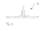
- Figure 1 shows an arrangement 10 for manufacturing a composite material component 12, the composite material component 12 being depicted in Figure 3 .
- the arrangement 10 comprises a tool 14 which is adapted to receive a semi-finished part 16.
- the tool 14 is designed in the form of a supporting tool having a supporting surface 18 adapted to support the semi-finished part 16 thereon.
- the shape of the supporting surface 18 of the tool 14 is adapted to the shape of a surface of the semi-finished part 16 facing the supporting surface 18 of the tool 14.
- the supporting surface 18 of the tool 14 is a planar surface. It is, however, also conceivable to provide the tool 14 with a curved supporting surface 18, in particular in case a composite material component 12 having a curved surface should be produced.
- the semi-finished part 16 comprises a first element 20 which is adapted to form an aircraft outer shell.
- a second element 22 of the semi-finished part 16 extends substantially perpendicular to the first element 20 and is adapted to form a stiffening element enhancing the mechanical properties of an aircraft outer shell.
- the semi-finished part 16 comprises two third elements 24a, 24b which are adapted to form connecting elements connecting a stiffening element to an aircraft outer shell.
- the first element 20, the second element 22 and the third elements 24a, 24b of the semi-finished part 16 are made of fiber prepregs, i.e. pre-formed fibers, in particular carbon fibers which are impregnated with a thermoset plastic material, in particular a resin material such as, for example, an epoxy resin material. It is, however, also conceivable to use a first element 20 and a second element 22 which contain an already cured thermoset plastic material such that only the third elements 24a, 24b of the semi-finished part 16 have to undergo a curing process.
- the arrangement further comprises a spraying device 26 which is adapted to spray a sprayable material onto the tool 14 and the semi-finished part 16.
- the spraying device 26 is designed in the form of a movable device such that the spraying device 26 can be moved relative to the tool 14 and the semi-finished part 16 as desired during spraying a sprayable material onto the tool 14 and the semi-finished part 16. It is, however, also conceivable to design the spraying device 26 in the form of a fixed device and to provide for a movable support which allows moving the tool 14 and the semi-finished part 16 relative to the spraying device 26.
- the spraying device 26 contains a storage space 28 which is filled with the sprayable material.
- the storage space 28 is sub-divided into a first compartment 28a and a second compartment 28b allowing a two-component sprayable material to be received within the storage space 28 in such a manner that contact between the two components of the sprayable material received within the first and the second compartment 28a, 28b of the storage space 28 is reliably prevented.
- the storage space 28, via a supply line 30, is connected to a spraying nozzle 32.
- the spraying nozzle 32 provides for a uniform distribution of the sprayable material, wherein the supply line 30 is made of a flexible material allowing the spraying nozzle 32 to be conveniently moved as desired.
- the sprayable material contained in the storage space 28 of the spraying device 26 is a polymer material which, after being sprayed onto the tool 14 and the semi-finished part 16 by means of the spraying device 26 generates a vacuum bag 34, the vacuum bag 34 being configured to seal a receiving space 36 for receiving the semi-finished part 16 against the ambient atmosphere, see Figure 2 .
- the receiving space 36 is defined by the vacuum bag 34 covering the semi-finished part 16 and the supporting surface 18 of the tool 14.
- the vacuum bag 34 is connected to the tool 14, i.e. the supporting surface 18 of the fool 14 in a sealing manner.
- the sealing connection between the vacuum bag 34 and the supporting surface 18 of the tool 14 is achieved upon spraying the sprayable material used for generating the vacuum bag 34 onto the semi-finished part 16 and the tool 14. It is, however, also conceivable to use an additional sealing element, for example in the form of a sealing tape to sealingly connect the vacuum bag 34 to the supporting surface 18 of the tool 14. Further, it is conceivable to spray the sprayable material onto the tool 14 and the semi-finished part 16 in such a manner that a vacuum bag 34 is generated which defines a receiving space 36 enveloping the tool 14 and the semi-finished part 16.
- the sprayable material which, in the exemplary embodiment discussed herein, is a two-component material, is cured by a chemical reaction initiated by bringing the two components of the sprayable material received within the first and the second compartment 28a, 28b of the storage space 28 of the spraying device 26 into contact with each other upon spraying the sprayable material onto the tool 14 and the semi-finished part 16.
- the sprayable material forms a vacuum bag 34 which is air tight up to a temperature of approximately 200°C and up to a pressure of approximately 12 bar.
- the tool 14 and the semi-finished part 16 which is received within the receiving space 36 defined by the vacuum bag 34 and the supporting surface 18 of the tool 14 thus may be placed within an autoclave 38, wherein the thermoset plastic material contained within the semi-finished part 16 is cured under an elevated temperature and an elevated pressure in order to obtain the composite material component 12 depicted in Figure 3 .
- the semi-finished part 16 and a region of the supporting surface 18 of the tool 14 adjacent to the semi-finished part 16 is covered by a peel ply 40, a perforated release foil 42 and a gating fabric tape 44. While the peal ply 40 and the perforated release foil 42 simplify releasing the vacuum bag 34 from the tool 14 and the composite material component 12 after completion of the autoclave process, the gating fabric tape 44 allows air to be removed from the receiving space 36 when the receiving space 36 is connected to a vacuum source (not shown in the drawings).
- the vacuum bag 34 generated from the sprayable material has a uniform thickness.
- the vacuum bag 34 may have a larger thickness thus increasing the strength of the vacuum bag 34 in these critical regions.
- damages to the vacuum bag 34 for example during the autoclave process, can be reliably prevented.
- the vacuum bag 34 due to being made from a sprayable material, exactly fits to the contour of the semi-finished part 16 and the supporting surface 18 of the tool 14.
- the semi-finished part 16, within the autoclave 38 can be supported in its position by means of a retaining means 46 which is arranged outside of the vacuum bag 34.
Landscapes
- Chemical & Material Sciences (AREA)
- Engineering & Computer Science (AREA)
- Composite Materials (AREA)
- Mechanical Engineering (AREA)
- Moulding By Coating Moulds (AREA)
- Casting Or Compression Moulding Of Plastics Or The Like (AREA)
Priority Applications (2)
| Application Number | Priority Date | Filing Date | Title |
|---|---|---|---|
| EP20130193464 EP2873516A1 (fr) | 2013-11-19 | 2013-11-19 | Procédé et dispositif de fabrication d'un composant de matériau composite |
| US14/538,412 US20160159015A1 (en) | 2013-11-19 | 2014-11-11 | Method and arrangement for manufacturing a composite material component |
Applications Claiming Priority (1)
| Application Number | Priority Date | Filing Date | Title |
|---|---|---|---|
| EP20130193464 EP2873516A1 (fr) | 2013-11-19 | 2013-11-19 | Procédé et dispositif de fabrication d'un composant de matériau composite |
Publications (1)
| Publication Number | Publication Date |
|---|---|
| EP2873516A1 true EP2873516A1 (fr) | 2015-05-20 |
Family
ID=49585323
Family Applications (1)
| Application Number | Title | Priority Date | Filing Date |
|---|---|---|---|
| EP20130193464 Withdrawn EP2873516A1 (fr) | 2013-11-19 | 2013-11-19 | Procédé et dispositif de fabrication d'un composant de matériau composite |
Country Status (2)
| Country | Link |
|---|---|
| US (1) | US20160159015A1 (fr) |
| EP (1) | EP2873516A1 (fr) |
Cited By (2)
| Publication number | Priority date | Publication date | Assignee | Title |
|---|---|---|---|---|
| EP3115184A1 (fr) * | 2015-07-08 | 2017-01-11 | Airbus Operations GmbH | Procédé et système améliorés d'ensachage sous vide |
| FR3092785A1 (fr) * | 2019-02-19 | 2020-08-21 | Airbus Operations | procédé de formage d’un film d’ensachage sous vide comprenant la formation de nervures par flambage du film |
Citations (1)
| Publication number | Priority date | Publication date | Assignee | Title |
|---|---|---|---|---|
| DE102005026010B4 (de) | 2005-06-07 | 2010-12-30 | Airbus Deutschland Gmbh | Verfahren zur Herstellung einer verstärkten Schale zur Bildung von Teilkomponenten für Luftfahrzeuge |
Family Cites Families (7)
| Publication number | Priority date | Publication date | Assignee | Title |
|---|---|---|---|---|
| US6723273B2 (en) * | 2002-09-11 | 2004-04-20 | Keith Johnson | Curable liquid sealant used as vacuum bag in composite manufacturing |
| US7014809B2 (en) * | 2004-07-30 | 2006-03-21 | Audette Lawrence F | Process for making a reusable soft bag for use in infusion processes for making plastic parts |
| US20080106007A1 (en) * | 2006-10-17 | 2008-05-08 | Kipp Michael D | Resin infusion process utilizing a reusable vacuum bag |
| WO2008086022A1 (fr) * | 2007-01-09 | 2008-07-17 | American Consulting Technology & Research Inc. | Sac sous vide multifonction pour fabrication de pièce composite |
| EP2134523A4 (fr) * | 2007-02-23 | 2013-12-04 | Richard W Rydin | Procédé de fabrication et d'utilisation d'un sac sous vide en caoutchouc naturel formé par pulvérisation |
| US8672665B2 (en) * | 2007-05-18 | 2014-03-18 | Arjr Group, Llc | Vacuum bag with integral fluid transfer conduits and seals for resin transfer and other processes |
| EP2871046A1 (fr) * | 2013-11-06 | 2015-05-13 | Airbus Operations GmbH | Agencement de port de connexion destiné à être utilisé dans un appareil de production de composant de matériau composite |
-
2013
- 2013-11-19 EP EP20130193464 patent/EP2873516A1/fr not_active Withdrawn
-
2014
- 2014-11-11 US US14/538,412 patent/US20160159015A1/en not_active Abandoned
Patent Citations (2)
| Publication number | Priority date | Publication date | Assignee | Title |
|---|---|---|---|---|
| DE102005026010B4 (de) | 2005-06-07 | 2010-12-30 | Airbus Deutschland Gmbh | Verfahren zur Herstellung einer verstärkten Schale zur Bildung von Teilkomponenten für Luftfahrzeuge |
| US7897095B2 (en) | 2005-06-07 | 2011-03-01 | Airbus Operations Gmbh | Method for manufacturing a reinforced shell for forming component parts for aircraft and shell for component parts for aircraft |
Non-Patent Citations (2)
| Title |
|---|
| ALAN HARPER ET AL.: "Reusable Silicone Bags, new analysis report provides "Clean bill of health" for use in advanced composites", ADVANCED COMPOSITES MANUFACTURING EVENT, 1 September 2012 (2012-09-01), Plymouth, XP002723449 * |
| SMOOTH-ON INC.: "How to make a reusable silicone vacuum bag for resin infusion", 17 October 2011 (2011-10-17), XP002723450, Retrieved from the Internet <URL:https://www.youtube.com/watch?v=XcJ-ErEVrsY#t=43> [retrieved on 20140422] * |
Cited By (3)
| Publication number | Priority date | Publication date | Assignee | Title |
|---|---|---|---|---|
| EP3115184A1 (fr) * | 2015-07-08 | 2017-01-11 | Airbus Operations GmbH | Procédé et système améliorés d'ensachage sous vide |
| US10307943B2 (en) | 2015-07-08 | 2019-06-04 | Airbus Operations Gmbh | Method and system for vacuum bagging |
| FR3092785A1 (fr) * | 2019-02-19 | 2020-08-21 | Airbus Operations | procédé de formage d’un film d’ensachage sous vide comprenant la formation de nervures par flambage du film |
Also Published As
| Publication number | Publication date |
|---|---|
| US20160159015A1 (en) | 2016-06-09 |
Similar Documents
| Publication | Publication Date | Title |
|---|---|---|
| US9234500B2 (en) | Method of producing a composite shell structure | |
| KR101995529B1 (ko) | 섬유 강화 복합 몰딩 | |
| EP2886446B1 (fr) | Cloison de pressurisation pour avion | |
| US20160297153A1 (en) | Method for impregnation of a fibrous preform and device for implementation of the said method | |
| US11701797B2 (en) | Composite material molding jig and composite material molding method | |
| CA2802877C (fr) | Profile support, procede de fabrication d'un profile support et son utilisation dans un procede de fabrication d'un element renforce d'une carcasse de vehicule | |
| JP6797601B2 (ja) | テクスチャ加工された当て板及び使用方法 | |
| US8197244B2 (en) | Multilayer, flexible planar material | |
| JP2007260925A (ja) | 繊維強化プラスチックの製造方法および繊維強化プラスチック並びにプリフォーム | |
| US9550331B2 (en) | Method and device for producing a composite molded part from fiber-reinforced plastic | |
| US7662334B2 (en) | Vacuum heat-set of net shape latex vacuum bags | |
| US20140186574A1 (en) | Method for producing and connecting fibre-reinforced components and aircraft or spacecraft | |
| JP5017976B2 (ja) | 繊維強化樹脂部材の製造方法および製造装置 | |
| EP2873516A1 (fr) | Procédé et dispositif de fabrication d'un composant de matériau composite | |
| KR101447136B1 (ko) | 섬유 강화 복합재의 성형방법 | |
| CN110914046B (zh) | 多阶段树脂输送 | |
| US10807323B2 (en) | Manufacture of objects having a fiber-reinforced region | |
| US20140328690A1 (en) | Perforated vacuum membrane for fibre reinforced laminates | |
| EP2915656B1 (fr) | Procédé de fabrication d'un composant pour éolienne | |
| US20170151710A1 (en) | Method for manufacturing an aircraft structure component | |
| US10661507B2 (en) | Assembly having individual components made of a fibre-reinforced composite material | |
| KR20150062195A (ko) | 탄소섬유강화플라스틱 가압 성형장치 및 탄소섬유강화플라스틱 가압 성형방법 | |
| JP6048967B2 (ja) | 繊維強化プラスチック成形体の製造方法及び製造装置、並びにエレベータの壁 | |
| EP2736706B1 (fr) | Dispositif pour la fabrication d'un composant lié et procédé de fabrication | |
| JP2009172863A (ja) | 繊維強化樹脂構造体の製造方法 |
Legal Events
| Date | Code | Title | Description |
|---|---|---|---|
| PUAI | Public reference made under article 153(3) epc to a published international application that has entered the european phase |
Free format text: ORIGINAL CODE: 0009012 |
|
| 17P | Request for examination filed |
Effective date: 20131119 |
|
| AK | Designated contracting states |
Kind code of ref document: A1 Designated state(s): AL AT BE BG CH CY CZ DE DK EE ES FI FR GB GR HR HU IE IS IT LI LT LU LV MC MK MT NL NO PL PT RO RS SE SI SK SM TR |
|
| AX | Request for extension of the european patent |
Extension state: BA ME |
|
| R17P | Request for examination filed (corrected) |
Effective date: 20150923 |
|
| RBV | Designated contracting states (corrected) |
Designated state(s): AL AT BE BG CH CY CZ DE DK EE ES FI FR GB GR HR HU IE IS IT LI LT LU LV MC MK MT NL NO PL PT RO RS SE SI SK SM TR |
|
| GRAP | Despatch of communication of intention to grant a patent |
Free format text: ORIGINAL CODE: EPIDOSNIGR1 |
|
| STAA | Information on the status of an ep patent application or granted ep patent |
Free format text: STATUS: GRANT OF PATENT IS INTENDED |
|
| INTG | Intention to grant announced |
Effective date: 20170124 |
|
| STAA | Information on the status of an ep patent application or granted ep patent |
Free format text: STATUS: THE APPLICATION IS DEEMED TO BE WITHDRAWN |
|
| 18D | Application deemed to be withdrawn |
Effective date: 20170607 |