EP2871347A1 - Internal combustion engine - Google Patents
Internal combustion engine Download PDFInfo
- Publication number
- EP2871347A1 EP2871347A1 EP20120880861 EP12880861A EP2871347A1 EP 2871347 A1 EP2871347 A1 EP 2871347A1 EP 20120880861 EP20120880861 EP 20120880861 EP 12880861 A EP12880861 A EP 12880861A EP 2871347 A1 EP2871347 A1 EP 2871347A1
- Authority
- EP
- European Patent Office
- Prior art keywords
- cylinder
- internal combustion
- combustion engine
- cylinder head
- cylinder block
- Prior art date
- Legal status (The legal status is an assumption and is not a legal conclusion. Google has not performed a legal analysis and makes no representation as to the accuracy of the status listed.)
- Granted
Links
Images





Classifications
-
- F—MECHANICAL ENGINEERING; LIGHTING; HEATING; WEAPONS; BLASTING
- F02—COMBUSTION ENGINES; HOT-GAS OR COMBUSTION-PRODUCT ENGINE PLANTS
- F02D—CONTROLLING COMBUSTION ENGINES
- F02D15/00—Varying compression ratio
- F02D15/02—Varying compression ratio by alteration or displacement of piston stroke
-
- F—MECHANICAL ENGINEERING; LIGHTING; HEATING; WEAPONS; BLASTING
- F02—COMBUSTION ENGINES; HOT-GAS OR COMBUSTION-PRODUCT ENGINE PLANTS
- F02B—INTERNAL-COMBUSTION PISTON ENGINES; COMBUSTION ENGINES IN GENERAL
- F02B75/00—Other engines
- F02B75/04—Engines with variable distances between pistons at top dead-centre positions and cylinder heads
- F02B75/041—Engines with variable distances between pistons at top dead-centre positions and cylinder heads by means of cylinder or cylinderhead positioning
-
- F—MECHANICAL ENGINEERING; LIGHTING; HEATING; WEAPONS; BLASTING
- F02—COMBUSTION ENGINES; HOT-GAS OR COMBUSTION-PRODUCT ENGINE PLANTS
- F02D—CONTROLLING COMBUSTION ENGINES
- F02D15/00—Varying compression ratio
- F02D15/04—Varying compression ratio by alteration of volume of compression space without changing piston stroke
-
- F—MECHANICAL ENGINEERING; LIGHTING; HEATING; WEAPONS; BLASTING
- F02—COMBUSTION ENGINES; HOT-GAS OR COMBUSTION-PRODUCT ENGINE PLANTS
- F02F—CYLINDERS, PISTONS OR CASINGS, FOR COMBUSTION ENGINES; ARRANGEMENTS OF SEALINGS IN COMBUSTION ENGINES
- F02F1/00—Cylinders; Cylinder heads
- F02F1/24—Cylinder heads
- F02F1/26—Cylinder heads having cooling means
Definitions
- the present invention relates to an internal combustion engine.
- Japanese Patent Publication No. 2008-075602A discloses a variable compression ratio mechanism which can change relative positions of a crankcase and a cylinder block in a cylinder axial direction so as to change the volumes of combustion chambers when pistons are positioned at compression top dead center.
- Japanese Patent Publication No. 60-22030A discloses a variable compression ratio engine in which a cylinder block is joined to a crankcase or cylinder head by a shape memory alloy. It discloses that this shape memory alloy is formed so as to contract in a cylinder axial direction at a low temperature side and to expand at a high temperature side.
- Japanese Patent Publication No. 2008-045443A discloses an internal combustion engine which is provided with a variable compression ratio mechanism which makes a cylinder block move relative to a crankcase wherein the cylinder block and the crankcase have a spring mechanism provided between them. This spring mechanism biases the cylinder block and the crankcase in a direction making them approach each other.
- Japanese Patent Publication No. 2011-153597A discloses an internal combustion engine which is provided with a variable compression ratio mechanism which makes a cylinder block move relative to a crankcase wherein a water jacket is formed which runs cooling water to the inside of a cylinder head.
- Japanese Patent Publication No. 2011-144789A discloses an internal combustion engine which is provided with a variable compression ratio mechanism which makes a cylinder block move relative to a crankcase wherein the cylinder block and the crankcase have a ring-shaped seal member provided between them. This discloses that the seal member is formed so as to cover the clearance between the cylinder block and the crankcase over the entire circumference of the internal combustion engine.
- Japanese Patent Publication No. 2010-106710A discloses a cylinder liner which is provided in a cylinder block and which slides with a piston.
- This cylinder liner has a sliding surface part which allows the piston to slide and a nonsliding surface part which does not contact the piston.
- the sliding surface part is comprised of an inner wall surface of a cylindrical member, while the nonsliding surface part is comprised of the end part of the cylindrical member which is gradually increased in diameter from the inner wall surface outward in the radial direction to form an inclined surface.
- the plurality of cylinders from the #1 cylinder to the #4 cylinder are arranged in a single line. If combustion occurs in the #1 cylinder, a combustion load is applied to the cylinder head. At this time, due to elastic deformation of the cylinder block, elastic deformation of the crankcase, clearance of the bearings of the variable compression ratio mechanism, etc., the end part of the cylinder block at which the #1 cylinder is arranged rises up. At the end part at the opposite side where the #4 cylinder is arranged, no combustion occurs, so the part descends. After that, if combustion occurs at the #4 cylinder, the end part where the #4 cylinder is arranged rises while the end part where the #1 cylinder is arranged descends.
- the pistons are connected through connecting rods to a crankshaft, so the cylinder block is subjected to a force in a direction (thrust direction) vertical to the direction in which the pistons move back and forth.
- the thrust force due to the pistons acts on the cylinder block whereby, due to elastic deformation of the cylinder block, elastic deformation of the crankcase, clearance at the bearings of the variable compression ratio mechanism, etc., the cylinder head sometimes rolls with respect to the crankcase.
- Motion occurs whereby the cylinder block slants with respect to the crankcase in the width direction. This motion occurs along the direction vertical to the direction in which the plurality of cylinders are arranged and is called "rolling motion.” An internal combustion engine will sometime vibrates due to this rolling motion.
- the inertia force of the reciprocating motion of the pistons sometimes causes the crankcase to vibrate in the direction of movement of the pistons.
- Such vibration acts on the cylinder block and sometimes causes a lifting motion where the cylinder block moves in the direction of the reciprocating motion of the piston.
- the crankcase and the cylinder block have a spring arranged between them. In such a case as well, if the load which is applied from the cylinder block to the spring becomes a predetermined value or more, vibration derived from the lifting motion will sometimes occur.
- the present invention has as its object the provision of an internal combustion engine which is provided with a variable compression ratio mechanism which can suppress vibration.
- the internal combustion engine of the present invention is provided with a cylinder block which has a hole inside of which a piston is arranged, a cylinder head which includes a recess which has a top surface of a combustion chamber, a cylinder liner which is fastened at a surface of the hole of the cylinder block and which the piston contacts, and a variable compression ratio mechanism which changes a mechanical compression ratio.
- the variable compression ratio mechanism is formed so that the cylinder head is moved relative to the cylinder block whereby the combustion chamber is variably formed in size.
- the cylinder liner extends so that, in the range where the cylinder head moves relative to the cylinder block, an end part facing the cylinder head is arranged inside of the recess of the cylinder head.
- the end part of the cylinder liner can be formed so as to stick out from the cylinder block and can slide with respect to the recess of the cylinder head.
- an elastic member can be provided which is arranged between the cylinder block and the cylinder head and biases the cylinder head with respect to the cylinder block, and the elastic member can be arranged around a cylinder liner and can have a shape which surrounds the cylinder liner.
- the cylinder liner can be formed so that the end part which faces the cylinder head gradually becomes thinner the further toward a front end.
- the cylinder head can have a channel for cooling water which is formed at a side of a region in which the end part of the cylinder liner is inserted into the recess.
- a sealing member is provided which is arranged between the cylinder block and the cylinder head, and the sealing member is arranged around the cylinder liner for each cylinder and has a shape which surrounds the cylinder liner.
- an internal combustion engine in the embodiment will be explained.
- an internal combustion engine which is arranged in a vehicle will be taken up as an example.
- FIG. 1 is a schematic view of an internal combustion engine in the present embodiment.
- the internal combustion engine in the present embodiment is a spark ignition type.
- the internal combustion engine is provided with an engine body 1.
- the engine body 1 includes a cylinder block 2 and a cylinder head 4. Inside of the cylinder block 2, pistons 3 are arranged.
- a combustion chamber 5 is formed for each cylinder.
- an engine intake passage and engine exhaust passage are connected.
- an intake port 7 and exhaust port 9 are formed.
- An intake valve 6 is arranged at an end part of the intake port 7 and is formed to be able to open and close the engine intake passage which communicates with the combustion chamber 5.
- An exhaust valve 8 is arranged at an end part of the exhaust port 9 and is formed to be able to open and close the engine exhaust passage which communicates with the combustion chamber 5.
- an ignition device constituted by a spark plug 10 is fastened. The spark plug 10 is formed so as to ignite the fuel at the combustion chamber 5.
- the internal combustion engine in the present embodiment is provided with a fuel injector 11 for feeding fuel to each combustion chamber 5.
- the fuel injector 11 in the present embodiment is arranged so as to inject fuel to the intake port 7.
- the fuel injector 11 is not limited to this and may also be arranged so as to feed fuel to the combustion chamber 5.
- the fuel injector may also be arranged so as to directly inject fuel to the combustion chamber.
- the cylinder block 2 has holes 2a. At the surfaces of the holes 2a, cylinder liners 15 are fastened.
- the cylinder liners 15 in the present embodiment are formed into cylindrical shapes.
- the pistons 3 contact the cylinder liners 15. Further, the pistons 3 slide with respect to the cylinder liners 15.
- the pistons 3 are supported by a crankshaft 59 through connecting rods 58.
- the pistons 3 engage in reciprocating motion between top dead center and bottom dead center. Due to the reciprocating motion of the pistons 3, the crankshaft 59 rotates.
- the internal combustion engine in the present embodiment is provided with a supporting structure which supports the crankshaft 59.
- the supporting structure in the present embodiment includes the cylinder block 2.
- the cylinder block 2 includes a part inside of which the pistons 3 are arranged and also a crankcase part 79 and oil pan part 60. Inside of the crankcase part 79, the crankshaft 59 is arranged. Further, the crankshaft 59 is supported by the crankcase part 79.
- the oil pan part 60 is fastened to the crankcase part 79. Inside of the oil pan part 60, oil 61 which lubricates the members which are included in the engine body 1 is stored.
- the internal combustion engine in the present embodiment is provided with an electronic control unit 31.
- the electronic control unit 31 in the present embodiment includes a digital computer and functions as a control device. Output signals of various sensors such as an air flow meter which is arranged in the engine intake passage, a crank angle sensor which is arranged around the crankshaft 59, and a temperature sensor which is arranged at a predetermined position are input to the electronic control unit 31.
- the electronic control unit 31 is connected through corresponding drive circuits to the fuel injectors 11 and spark plugs 10.
- the electronic control unit 31 in the present embodiment is formed so as to perform fuel injection control or ignition control.
- a step motor which drives a throttle valve which is arranged in the engine intake passage, a fuel pump, and other equipment which are contained in the internal combustion engine are controlled by the electronic control unit 31.
- the internal combustion engine in the present embodiment is provided with a variable compression ratio mechanism.
- a space which is surrounded by a recess 4a of the cylinder head 4 and a crown of a piston 3 when the piston is positioned at compression top dead center will be called a "combustion chamber”.
- the compression ratio of the internal combustion engine is determined by the volumes etc. of the combustion chambers.
- the variable compression ratio mechanism in the present embodiment is formed to change the volumes of the combustion chambers so as to change the compression ratio.
- FIG. 2 is a disassembled perspective view of a variable compression ratio mechanism of an internal combustion engine in the present embodiment.
- FIG. 3 is a first schematic cross-sectional view of a part of a combustion chamber in the internal combustion engine.
- FIG. 3 is a schematic view when the variable compression ratio mechanism is used to set a high compression ratio.
- the internal combustion engine in the present embodiment is configured so that a supporting structure which includes the cylinder block 2 and a cylinder head 4 which is arranged at a top side of the supporting structure move relative to each other.
- the cylinder block 2 in the present embodiment supports the cylinder head 4 through the variable compression ratio mechanism.
- a plurality of projecting parts 80 are formed at the bottoms of the side walls at the both sides of the cylinder head 4.
- cam insertion holes 81 with circular cross-sectional shapes are formed at the projecting parts 80.
- cam insertion holes 83 with circular cross-sectional shapes are formed at the projecting parts 82 of the cylinder block 2 fit between the projecting parts 80 of the cylinder head 4.
- the variable compression ratio mechanism in the present embodiment includes a pair of camshafts 84 and 85 serving as support shafts for the cylinder head 4.
- the camshafts 84 and 85 include circular cams 88 which are rotably inserted inside the respective cam insertion holes 83.
- the circular cams 88 are arranged coaxially with the axes of rotation of the camshafts 84 and 85.
- eccentric shafts 87 which are arranged eccentrically with respect to the axes of rotation of the camshafts 84 and 85 extend.
- other circular cams 86 are attached eccentrically to be able to rotate.
- These circular cams 86 are arranged at the both sides of the circular cams 88.
- the circular cams 86 are inserted to be able to rotate in the corresponding cam insertion holes 81.
- the variable compression ratio mechanism includes a motor 89. At a shaft 90 of the motor 89, two worm gears 91 and 92 with spiral directions opposite to each other are attached. At the end parts of the camshafts 84 and 85, worm wheels 93 and 94 are fastened. The worm wheels 93 and 94 are arranged so as to mesh with the worm gears 91 and 92. By the motor 89 turning the shaft 90, the camshafts 84 and 85 can be made to rotate in mutually opposite directions.
- the motor 89 is connected through a corresponding drive circuit to the electronic control unit 31.
- the motor 89 is controlled by the electronic control unit 31. That is, the variable compression ratio mechanism in the present embodiment is controlled by the electronic control unit 31.
- the eccentric shafts 87 move toward the top ends of the circular cams 88.
- the circular cams 86 rotate in opposite directions from the circular cams 88 inside the cam insertion holes 81 as shown by the arrow marks 96.
- FIG. 4 shows a second schematic cross-sectional view of a part of the combustion chamber in the internal combustion engine of the present embodiment.
- FIG. 4 is a schematic view of the time when the variable compression ratio mechanism is used to set a low compression ratio.
- the eccentric shaft 87 moves up to the top end of the circular cam 88
- the center axis of the circular cam 88 moves below even more than the eccentric shaft 87.
- the relative positions of the cylinder block 2 and cylinder head 4 are determined by the distance between the center axis of the circular cam 86 and the center axis of the circular cam 88.
- variable compression ratio mechanism in the present embodiment is configured to make the cylinder head 4 move relative to the cylinder block 2 so as to enable the combustion chambers 5 to be changed in volume.
- the compression ratio which is determined by only the stroke volume of a piston from bottom dead center to top dead center and the volume of a combustion chamber will be referred to as the "mechanical compression ratio".
- the piston 3 has reached compression top dead center and the combustion chamber 5 has become small in volume. If the amount of intake air is constant, the compression ratio rises. This state is the state of a high mechanical compression ratio. As opposed to this, in FIG. 4 , the piston 3 reaches compression top dead center and the combustion chamber 5 becomes large in volume. If the amount of intake air is constant, the compression ratio falls. This state is the state of a low mechanical compression ratio.
- the internal combustion engine in the present embodiment enables the compression ratio to be changed during the operating period.
- the variable compression ratio mechanism can be used to change the compression ratio in accordance with the operating state of the internal combustion engine.
- the actually effective compression ratio that is, the "actual compression ratio”
- the variable valve mechanism and the variable compression ratio mechanism can be operated to change the actual compression ratio.
- variable compression ratio mechanism in the present embodiment is configured to make the circular cams provided eccentrically on the shaft rotate so as to make the cylinder head move relative to the cylinder block, but the invention is not limited to this. It is possible to employ any mechanism which makes the cylinder head move relative to the cylinder block.
- each cylinder liner 15 in the present embodiment has an end part 15a at the side facing the cylinder head 4.
- the end part 15a in the present embodiment is formed so as to stick out from the cylinder block 2.
- the cylinder head 4 is formed with recesses 4a for forming the combustion chambers 5.
- the recesses 4a have top surfaces of the combustion chambers 5.
- the recesses 4a are formed so that end parts 15a of the cylinder liners 15 can be inserted into them.
- the end parts 15a of the cylinder liners 15 are fit into the recesses 4a of the cylinder head 4.
- the cylinder head 4 moves relative to the cylinder block 2 in the direction of movement of the pistons 3.
- the end parts 15a of the cylinder liners 15 slide relative to the recesses 4a of the cylinder head 4.
- the cylinder liners 15 extend so that the end parts 15a are arranged inside of the recesses 4a of the cylinder head 4 in the range where the cylinder head 4 can move relative to the cylinder block 2.
- the combustion chambers 5 can be sealed and, furthermore, the combustion chambers 5 can be changed in volume.
- an internal combustion engine which comprises a crankcase and a cylinder block which are formed individually and is provided with a variable compression ratio mechanism which makes the cylinder block move relative to the crankcase will be taken up as an example.
- the crankcase becomes the non-moving part, while the cylinder block and cylinder head become the integral moving parts.
- the cylinder block 2 includes the crankcase part, and the part where the pistons are arranged and the crankcase part can be integrally formed. For this reason, it is possible to raise the rigidity of the non-moving part which includes the cylinder block. It is possible to reduce the pitching motion of pitching in the direction of arrangement of cylinders in the internal combustion engine. As a result, vibration which is due to pitching motion can be reduced.
- an elastic member may be arranged at the internal combustion engine to suppress lifting motion.
- the moving part in this embodiment is light in weight since it does not include the cylinder block and is constituted by the cylinder head. For this reason, the inertia force of the moving part becomes smaller and therefore an elastic member can be used to effectively suppress the lifting motion. As a result, vibration derived from lifting motion can be reduced.
- the elastic member can be made smaller. In this way, the internal combustion engine of the present embodiment can effectively suppress vibration.
- head bolts for fastening the cylinder head 4 to the cylinder block 2 become unnecessary. For this reason, deformation of the holes 2a of the cylinder block 2 due to fastening of the head bolts can be suppressed. If deformation of the holes 2a of the cylinder block 2 is suppressed, when the pistons 3 move, the pressing forces of the piston rings 3a can be kept from becoming locally higher. Further, the friction between the piston rings 3a and the cylinder liners 15 can be reduced, so the ability of the piston rings 3a to track the liners can be improved. As a result, the amount of fuel consumption can be reduced.
- the amount of the blowby gas which passes between the pistons 3 and cylinder liners 15 and leaks from the combustion chambers 5 to the inside of the crankcase part 79 is reduced. For this reason, the unburned fuel is decreased and the amount of fuel consumption is improved.
- the piston rings 3a can effectively scrape off the oil.
- the oil which remains inside of the combustion chambers 5 can be reduced.
- the amount of consumption of oil can be reduced.
- the amount of blowby gas being reduced, when blowby gas is returned to the engine intake passage, the oil which is carried to the engine intake passage together with the blowby gas is reduced. For this reason, the amount of consumption of oil can be reduced.
- the part in which the pistons are arranged and the crankcase part which holds the crankshaft inside it can be formed integrally and therefore the productivity can be improved.
- the drive apparatus for driving the variable compression ratio mechanism can be made smaller.
- the motor 89 etc. which drives the circular cams 86 and 88 or camshafts 84 and 85 can be made smaller.
- the internal combustion engine can be made smaller in size and mounting in a vehicle etc. become easy.
- the internal combustion engine in the present embodiment is formed so that the end parts 15a of the cylinder liners 15 and the recesses 4a of the cylinder head 4 slide with each other, but the invention is not limited to this.
- Wall parts of the cylinder block body may also be formed around the cylinder liners. That is, the cylinder block body may be formed with engagement parts which stick out toward the cylinder head.
- the end parts of the cylinder liners may also be arranged at the inside surfaces of the engagement parts.
- the engagement parts of the cylinder block and the recesses of the cylinder head can be formed to engage with each other. Further, the engagement parts of the cylinder block can also be formed so as to slide with respect to the recesses of the cylinder head.
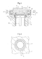
- FIG. 5 is a schematic cross-sectional view of the second internal combustion engine in the present embodiment.
- the second internal combustion engine is provided with an elastic member which is arranged between the cylinder block 2 and the cylinder head 4.
- a coil spring 16 is arranged as the elastic member of the present embodiment.
- FIG. 6 is a schematic cross-sectional view when cut along the part where the coil spring 16 is arranged in one cylinder.
- a cutaway part 12 is formed at the top part of the cylinder block 2.
- the cutaway part 12 is formed along the shape of the cylinder liner 15.
- the cutaway part 12 is formed so as to surround the cylinder liner 15.
- the coil spring 16 of the present embodiment is arranged for each cylinder.
- the coil springs 16 are arranged around the cylinder liners 15.
- the coil springs 16 have shapes which surround the cylinder liners 15.
- the coil springs 16 are arranged inside of the cutaway parts 12.
- the coil springs 16 in the present embodiment bias the cylinder head 4 in a direction making the cylinder head 4 separate from the cylinder block 2.
- the elastic members In the internal combustion engine of the present embodiment, it is possible to arrange the elastic members so as to surround the cylinder liners 15, so large elastic members can be employed.
- coil springs are arranged between the cylinder block and the crankcase. The space between the cylinder block and the crankcase is small, so small coil springs are arranged. In this case, the areas of the bearing surfaces where the coil springs are arranged become smaller and the stress at the bearing surfaces becomes higher. For this reason, cracks or other damage was liable to occur at the parts of the bearing surfaces of the crankcase or cylinder block. Furthermore, the coil springs bias the large weight moving parts such as the cylinder block and cylinder head, so the internal stress becomes large and damage easily occurs.
- the second internal combustion engine of the present embodiment it is possible to arrange large elastic members, so it is possible to increase the elastic forces of the elastic members and effectively suppress vibration. Further, by the elastic members becoming larger, the areas of the bearing surfaces where the elastic members are arranged become larger. It is possible to reduce the stress at the bearing surfaces. Furthermore, it is possible to reduce the stress which occurs inside the elastic members.
- Elastic members can be arranged for all of the cylinders. Alternatively, elastic members can be arranged for part of the cylinders among the plurality of cylinders. For example, in an inline-four internal combustion engine, elastic members may also be arranged at the #1 cylinder and the #4 cylinders and not arranged at the #2 cylinder and #3 cylinder.
- coil springs are arranged as the elastic members, but the invention is not limited to this. It is possible to employ any elastic members which bias the cylinder head in a direction away from the cylinder block.
- FIG. 7 is an enlarged cross-sectional view of an end part of a cylinder liner of the third internal combustion engine in the present embodiment.
- FIG. 7 shows the state where the mechanical compression ratio is high.
- the end part 15a of the cylinder liner 15 is inserted up to near the top surface of the combustion chamber 5.
- the cylinder liner 15 has an end part 15a facing the cylinder head 4 and slanted toward the inside of the combustion chamber 5 to give a tapered shape.
- the end part 15a has a pointed shape at its front end and has a shape which becomes gradually thinner toward the front end.
- the end face 15b of the cylinder liner 15 is slanted toward the combustion chamber 5.
- FIG. 8 shows an enlarged schematic cross-sectional view of an end part of a cylinder liner of a comparative example.
- the end part 15a of the cylinder liner 15 of the comparative example is formed with a substantially constant thickness.
- the end face 15b of the end part 15a is formed to become substantially vertical with respect to the direction in which the cylinder liner 15 extends.
- the space 19 sandwiched between the end face 15b and the top surface of the recess 4a of the cylinder head 4 becomes narrower. For this reason, at the space 19, the fuel will not burn or misfires will occur and in some cases unburned fuel will be produced.
- the end part 15a of the cylinder liner 15 is formed in a tapered shape, so the space 19 can be made larger.
- the space 19 can be made larger.
- the space 19 becomes narrower.
- production of unburned fuel at the space 19 can be suppressed and the amount of fuel consumption can be improved.
- variation of the combustion at the inside of the combustion chamber 5 can be suppressed. For this reason, vibration of the internal combustion engine can be more effectively suppressed.
- FIG. 9 is an enlarged schematic cross-sectional view of a part at the side of a combustion chamber in the fourth internal combustion engine of the present embodiment.
- the cylinder head 4 includes a channel for cooling water which is formed at the side of a region in which an end part 15a of a cylinder liner 15 is inserted into a recess 4a.
- the cooling water jacket 17 is formed as a channel for cooling water.
- the cooling water jacket 17 is formed near the recess 4a.
- the cooling water jacket 17 is formed at the outside of the cylinder liner 15.
- the cooling water jacket 17 extends in the direction in which the cylinder liner 15 extends.
- the heat which is generated in the combustion chamber 5 is transferred through the cylinder liner 15 to the cylinder head 4. For this reason, the wall surface of the combustion chamber 5 easily rises in temperature.
- the cooling water jacket 17 is formed at the side of the region where the end part 15a of the cylinder liner 15 is inserted, the wall surface of the combustion chamber 5 can be effectively cooled.
- each combustion chamber 5 substantially the entirety of each combustion chamber 5 is arranged inside of the cylinder head 4. If running cooling water to the cooling water jacket 17, it is possible to cool the surroundings of the combustion chamber 5. For this reason, it is not necessary to form the cooling water jacket around the holes 2a at the cylinder block 2. Since it is possible to eliminate the cooling water jacket around the holes 2a of the cylinder block 2, it is possible to simplify the structure of the cylinder block 2.
- FIG. 10 is a schematic cross-sectional view of the fifth internal combustion engine in the present embodiment.
- the fifth internal combustion engine in the present embodiment is provided with a sealing member, which is arranged between the cylinder block 2 and the cylinder head 4.
- a boot seal 18 is arranged as the sealing member.
- the boot seal 18 of the present embodiment is arranged at each of the cylinders.
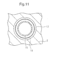
- FIG. 11 is a schematic cross-sectional view when cutting along the part where a boot seal 18 is arranged in one cylinder.
- the boot seal 18 is arranged around a cylinder liner 15.
- the boot seal 18 has a shape which surrounds the cylinder liner 15.
- the cylinder block 2 is formed with a cutaway part 12.
- the cutaway part 12 is formed so as to surround the cylinder liner 15.
- the boot seal 18 is arranged at the inside of the cutaway part 12.
- the boot seal 18 is formed to be able to deform along the direction of movement of the piston 3.
- the boot seal 18 in the present embodiment is formed in an accordion shape.
- One end part of the boot seal 18 is fastened to the cylinder head 4.
- the other end part of the boot seal 18 is fastened to the cylinder block 2.
- the boot seal 18 is formed to be able to expand and contract along with movement of the cylinder head 4 with respect to the cylinder block 2.
- a sealing member can be arranged.
- the sealing member it was necessary to arrange the sealing member so as to surround the cylinder block as a whole. For this reason, the sealing member became large in size.
- the sealing member it is possible to arrange the sealing member at the outside of the cylindrically shaped cylinder liner, so the sealing member can be made small in size.
- the sealing member in the present embodiment is arranged at each of the cylinders, but the invention is not limited to this. It is also possible to have a single sealing member be arranged for a plurality of cylinders. That is, a sealing member may also be arranged so as to surround a plurality of cylinders.
- the sealing member in the present embodiment includes an elastic boot seal, but the invention is not limited to this. Any member which can seal the part between the cylinder block and the cylinder head can be arranged.
- the sealing member may also be a ring-shaped member which fits around the outer circumference of the cylinder liner. Such an axial seal type of sealing member may also be press fit around the outside of the cylinder liner.
Landscapes
- Engineering & Computer Science (AREA)
- Chemical & Material Sciences (AREA)
- Combustion & Propulsion (AREA)
- Mechanical Engineering (AREA)
- General Engineering & Computer Science (AREA)
- Output Control And Ontrol Of Special Type Engine (AREA)
- Cylinder Crankcases Of Internal Combustion Engines (AREA)
Abstract
Description
- The present invention relates to an internal combustion engine.
- In a combustion chamber of an internal combustion engine, an air-fuel mixture of air and fuel is ignited in a compressed state. It is known that a compression ratio when compressing the air-fuel mixture has an effect on output torque and an amount of fuel consumption. It is possible to raise the compression ratio so as to increase the torque or so as to reduce the amount of fuel consumption. On the other hand, it is known that if making the compression ratio too high, knocking or other abnormal combustion phenomena will occur. In the prior art, there has therefore been known an internal combustion engine which is provided with a various compression ratio mechanism which enables the compression ratio to be changed during the operating period.
- Japanese Patent Publication No.
2008-075602A - Further, Japanese Patent Publication No.
60-22030A - Japanese Patent Publication No.
2008-045443A - Japanese Patent Publication No.
2011-153597A - Japanese Patent Publication No.
2011-144789A - Further, Japanese Patent Publication No.
2010-106710A -
- PLT 1. Japanese Patent Publication No.
2008-075602A - PLT 2. Japanese Patent Publication No.
60-22030A - PLT 3. Japanese Patent Publication No.
2008-045443A - PLT 4. Japanese Patent Publication No.
2011-153597A - PLT 5. Japanese Patent Publication No.
2011-144789A - PLT 6. Japanese Patent Publication No.
2010-106710A - As disclosed in the above-mentioned Japanese Patent Publication No.
2008-075602A 2008-045443A - For example, in an inline-four internal combustion engine, the plurality of cylinders from the #1 cylinder to the #4 cylinder are arranged in a single line. If combustion occurs in the #1 cylinder, a combustion load is applied to the cylinder head. At this time, due to elastic deformation of the cylinder block, elastic deformation of the crankcase, clearance of the bearings of the variable compression ratio mechanism, etc., the end part of the cylinder block at which the #1 cylinder is arranged rises up. At the end part at the opposite side where the #4 cylinder is arranged, no combustion occurs, so the part descends. After that, if combustion occurs at the #4 cylinder, the end part where the #4 cylinder is arranged rises while the end part where the #1 cylinder is arranged descends. If this phenomenon is repeated, motion called "pitching" where the cylinder head swings with respect to the crankcase will occur along the direction in which the plurality of cylinders are arranged (longitudinal direction). An internal combustion engine sometimes will vibrate due to this pitching motion.
- Further, the pistons are connected through connecting rods to a crankshaft, so the cylinder block is subjected to a force in a direction (thrust direction) vertical to the direction in which the pistons move back and forth. The thrust force due to the pistons acts on the cylinder block whereby, due to elastic deformation of the cylinder block, elastic deformation of the crankcase, clearance at the bearings of the variable compression ratio mechanism, etc., the cylinder head sometimes rolls with respect to the crankcase. Motion occurs whereby the cylinder block slants with respect to the crankcase in the width direction. This motion occurs along the direction vertical to the direction in which the plurality of cylinders are arranged and is called "rolling motion." An internal combustion engine will sometime vibrates due to this rolling motion.
- Furthermore, the inertia force of the reciprocating motion of the pistons sometimes causes the crankcase to vibrate in the direction of movement of the pistons. Such vibration acts on the cylinder block and sometimes causes a lifting motion where the cylinder block moves in the direction of the reciprocating motion of the piston. To suppress the lifting motion, sometimes the crankcase and the cylinder block have a spring arranged between them. In such a case as well, if the load which is applied from the cylinder block to the spring becomes a predetermined value or more, vibration derived from the lifting motion will sometimes occur.
- In this way, in an internal combustion engine which is provided with a variable compression ratio mechanism, there is the problem that vibration occurs due to the above-mentioned motions. Further, if vibration occurs, the cylinder block will move in the up-down direction and the left-right direction with respect to the crankcase, so at the bearings or at the slider etc. which are arranged between the crankcase and the cylinder block, a knocking sound will sometimes be generated.
- The present invention has as its object the provision of an internal combustion engine which is provided with a variable compression ratio mechanism which can suppress vibration.
- The internal combustion engine of the present invention is provided with a cylinder block which has a hole inside of which a piston is arranged, a cylinder head which includes a recess which has a top surface of a combustion chamber, a cylinder liner which is fastened at a surface of the hole of the cylinder block and which the piston contacts, and a variable compression ratio mechanism which changes a mechanical compression ratio. The variable compression ratio mechanism is formed so that the cylinder head is moved relative to the cylinder block whereby the combustion chamber is variably formed in size. The cylinder liner extends so that, in the range where the cylinder head moves relative to the cylinder block, an end part facing the cylinder head is arranged inside of the recess of the cylinder head.
- In the above invention, the end part of the cylinder liner can be formed so as to stick out from the cylinder block and can slide with respect to the recess of the cylinder head.
- In the above invention, an elastic member can be provided which is arranged between the cylinder block and the cylinder head and biases the cylinder head with respect to the cylinder block, and the elastic member can be arranged around a cylinder liner and can have a shape which surrounds the cylinder liner.
- In the above invention, the cylinder liner can be formed so that the end part which faces the cylinder head gradually becomes thinner the further toward a front end.
- In the above invention, the cylinder head can have a channel for cooling water which is formed at a side of a region in which the end part of the cylinder liner is inserted into the recess.
- In the above invention, preferably a sealing member is provided which is arranged between the cylinder block and the cylinder head, and the sealing member is arranged around the cylinder liner for each cylinder and has a shape which surrounds the cylinder liner.
- According to the present invention, it is possible to suppress vibration in an internal combustion engine which is provided with a variable compression ratio mechanism.
-
-
FIG. 1 is a schematic view of a first internal combustion engine in an embodiment. -
FIG. 2 is a schematic disassembled perspective view of a variable compression ratio mechanism in the embodiment. -
FIG. 3 is a schematic cross-sectional view of a cylinder block and cylinder head at the time where a mechanical compression ratio is a high compression ratio in the first internal combustion engine of the embodiment. -
FIG. 4 is a schematic cross-sectional view of a cylinder block and cylinder head at the time where a mechanical compression ratio is a low compression ratio in the first internal combustion engine of the embodiment. -
FIG. 5 is an enlarged schematic cross-sectional view of a cylinder block and cylinder head of a second internal combustion engine of the embodiment. -
FIG. 6 is a schematic cross-sectional view when cutting along a part where an elastic member is arranged in the second internal combustion engine of the embodiment. -
FIG. 7 is an enlarged schematic cross-sectional view of an end part of a cylinder liner of a third internal combustion engine of the embodiment. -
FIG. 8 is an enlarged schematic cross-sectional view of an end part of a cylinder liner of a comparative example. -
FIG. 9 is an enlarged schematic cross-sectional view of a side of a region in which an end part of a cylinder liner is inserted in a fourth internal combustion engine of the embodiment. -
FIG. 10 is a schematic cross-sectional view of a cylinder block and cylinder head in a fifth internal combustion engine of the embodiment. -
FIG. 11 is a schematic cross-sectional view when cutting along a part at which a sealing member is arranged in the fifth internal combustion engine of the embodiment. - Referring to
FIG. 1 to FIG. 11 , an internal combustion engine in the embodiment will be explained. In the present embodiment, an internal combustion engine which is arranged in a vehicle will be taken up as an example. -
FIG. 1 is a schematic view of an internal combustion engine in the present embodiment. The internal combustion engine in the present embodiment is a spark ignition type. The internal combustion engine is provided with an engine body 1. The engine body 1 includes acylinder block 2 and acylinder head 4. Inside of thecylinder block 2,pistons 3 are arranged. - A
combustion chamber 5 is formed for each cylinder. At thecombustion chamber 5, an engine intake passage and engine exhaust passage are connected. At thecylinder head 4, anintake port 7 andexhaust port 9 are formed. An intake valve 6 is arranged at an end part of theintake port 7 and is formed to be able to open and close the engine intake passage which communicates with thecombustion chamber 5. Anexhaust valve 8 is arranged at an end part of theexhaust port 9 and is formed to be able to open and close the engine exhaust passage which communicates with thecombustion chamber 5. At thecylinder head 4, an ignition device constituted by aspark plug 10 is fastened. Thespark plug 10 is formed so as to ignite the fuel at thecombustion chamber 5. - The internal combustion engine in the present embodiment is provided with a
fuel injector 11 for feeding fuel to eachcombustion chamber 5. Thefuel injector 11 in the present embodiment is arranged so as to inject fuel to theintake port 7. Thefuel injector 11 is not limited to this and may also be arranged so as to feed fuel to thecombustion chamber 5. For example, the fuel injector may also be arranged so as to directly inject fuel to the combustion chamber. - The
cylinder block 2 hasholes 2a. At the surfaces of theholes 2a,cylinder liners 15 are fastened. Thecylinder liners 15 in the present embodiment are formed into cylindrical shapes. Thepistons 3 contact thecylinder liners 15. Further, thepistons 3 slide with respect to thecylinder liners 15. Thepistons 3 are supported by acrankshaft 59 through connectingrods 58. Thepistons 3 engage in reciprocating motion between top dead center and bottom dead center. Due to the reciprocating motion of thepistons 3, thecrankshaft 59 rotates. - The internal combustion engine in the present embodiment is provided with a supporting structure which supports the
crankshaft 59. The supporting structure in the present embodiment includes thecylinder block 2. Thecylinder block 2 includes a part inside of which thepistons 3 are arranged and also acrankcase part 79 andoil pan part 60. Inside of thecrankcase part 79, thecrankshaft 59 is arranged. Further, thecrankshaft 59 is supported by thecrankcase part 79. Theoil pan part 60 is fastened to thecrankcase part 79. Inside of theoil pan part 60,oil 61 which lubricates the members which are included in the engine body 1 is stored. - The internal combustion engine in the present embodiment is provided with an
electronic control unit 31. Theelectronic control unit 31 in the present embodiment includes a digital computer and functions as a control device. Output signals of various sensors such as an air flow meter which is arranged in the engine intake passage, a crank angle sensor which is arranged around thecrankshaft 59, and a temperature sensor which is arranged at a predetermined position are input to theelectronic control unit 31. - The
electronic control unit 31 is connected through corresponding drive circuits to thefuel injectors 11 and spark plugs 10. Theelectronic control unit 31 in the present embodiment is formed so as to perform fuel injection control or ignition control. A step motor which drives a throttle valve which is arranged in the engine intake passage, a fuel pump, and other equipment which are contained in the internal combustion engine are controlled by theelectronic control unit 31. - The internal combustion engine in the present embodiment is provided with a variable compression ratio mechanism. In the present embodiment, a space which is surrounded by a
recess 4a of thecylinder head 4 and a crown of apiston 3 when the piston is positioned at compression top dead center will be called a "combustion chamber". The compression ratio of the internal combustion engine is determined by the volumes etc. of the combustion chambers. The variable compression ratio mechanism in the present embodiment is formed to change the volumes of the combustion chambers so as to change the compression ratio. The actually effective compression ratio in the combustion chamber, that is, the "actual compression ratio", is shown as (actual compression ratio)=(volume of combustion chamber + volume when piston moves in period when intake valve is closed)/(volume of combustion chamber). -
FIG. 2 is a disassembled perspective view of a variable compression ratio mechanism of an internal combustion engine in the present embodiment.FIG. 3 is a first schematic cross-sectional view of a part of a combustion chamber in the internal combustion engine.FIG. 3 is a schematic view when the variable compression ratio mechanism is used to set a high compression ratio. The internal combustion engine in the present embodiment is configured so that a supporting structure which includes thecylinder block 2 and acylinder head 4 which is arranged at a top side of the supporting structure move relative to each other. Thecylinder block 2 in the present embodiment supports thecylinder head 4 through the variable compression ratio mechanism. - Referring to
FIG. 2 andFIG. 3 , a plurality of projectingparts 80 are formed at the bottoms of the side walls at the both sides of thecylinder head 4. At the projectingparts 80, cam insertion holes 81 with circular cross-sectional shapes are formed. At the top wall of thecylinder block 2, a plurality of projectingparts 82 are formed. At the projectingparts 82, cam insertion holes 83 with circular cross-sectional shapes are formed. The projectingparts 82 of thecylinder block 2 fit between the projectingparts 80 of thecylinder head 4. - The variable compression ratio mechanism in the present embodiment includes a pair of
camshafts cylinder head 4. Thecamshafts circular cams 88 which are rotably inserted inside the respective cam insertion holes 83. Thecircular cams 88 are arranged coaxially with the axes of rotation of thecamshafts circular cams 88,eccentric shafts 87 which are arranged eccentrically with respect to the axes of rotation of thecamshafts eccentric shafts 87, othercircular cams 86 are attached eccentrically to be able to rotate. Thesecircular cams 86 are arranged at the both sides of thecircular cams 88. Thecircular cams 86 are inserted to be able to rotate in the corresponding cam insertion holes 81. - The variable compression ratio mechanism includes a
motor 89. At ashaft 90 of themotor 89, twoworm gears camshafts worm wheels worm wheels motor 89 turning theshaft 90, thecamshafts motor 89 is connected through a corresponding drive circuit to theelectronic control unit 31. Themotor 89 is controlled by theelectronic control unit 31. That is, the variable compression ratio mechanism in the present embodiment is controlled by theelectronic control unit 31. - Referring to
FIG. 3 , if thecircular cams 88 which are arranged on therespective camshafts eccentric shafts 87 move toward the top ends of thecircular cams 88. Thecircular cams 86 rotate in opposite directions from thecircular cams 88 inside the cam insertion holes 81 as shown by the arrow marks 96. -
FIG. 4 shows a second schematic cross-sectional view of a part of the combustion chamber in the internal combustion engine of the present embodiment.FIG. 4 is a schematic view of the time when the variable compression ratio mechanism is used to set a low compression ratio. As shown inFIG. 4 , if theeccentric shaft 87 moves up to the top end of thecircular cam 88, the center axis of thecircular cam 88 moves below even more than theeccentric shaft 87. Referring toFIG. 3 and FIG. 4 , the relative positions of thecylinder block 2 andcylinder head 4 are determined by the distance between the center axis of thecircular cam 86 and the center axis of thecircular cam 88. The larger the distance between the center axis of thecircular cam 86 and the center axis of thecircular cam 88, the further thecylinder head 4 moves in a direction away from thecylinder block 2. As shown by thearrow mark 98, the more thecylinder head 4 moves away from thecylinder block 2, the larger the volume of thecombustion chamber 5 when thepiston 3 reaches compression top dead center. - In this way, the variable compression ratio mechanism in the present embodiment is configured to make the
cylinder head 4 move relative to thecylinder block 2 so as to enable thecombustion chambers 5 to be changed in volume. In the present embodiment, the compression ratio which is determined by only the stroke volume of a piston from bottom dead center to top dead center and the volume of a combustion chamber will be referred to as the "mechanical compression ratio". The mechanical compression ratio is shown by (mechanical compression ratio)=(volume of combustion chamber + stroke volume of piston from bottom dead center to top dead center)/(volume of combustion chamber). - In
FIG. 3 , thepiston 3 has reached compression top dead center and thecombustion chamber 5 has become small in volume. If the amount of intake air is constant, the compression ratio rises. This state is the state of a high mechanical compression ratio. As opposed to this, inFIG. 4 , thepiston 3 reaches compression top dead center and thecombustion chamber 5 becomes large in volume. If the amount of intake air is constant, the compression ratio falls. This state is the state of a low mechanical compression ratio. In this way, the internal combustion engine in the present embodiment enables the compression ratio to be changed during the operating period. For example, the variable compression ratio mechanism can be used to change the compression ratio in accordance with the operating state of the internal combustion engine. - Note that, the actually effective compression ratio, that is, the "actual compression ratio", can be changed by changing the closing timing of the intake valve in addition to changing the mechanical compression ratio. When the internal combustion engine is provided with a variable valve mechanism which can change the closing timing of the intake valve, the variable valve mechanism and the variable compression ratio mechanism can be operated to change the actual compression ratio.
- The variable compression ratio mechanism in the present embodiment is configured to make the circular cams provided eccentrically on the shaft rotate so as to make the cylinder head move relative to the cylinder block, but the invention is not limited to this. It is possible to employ any mechanism which makes the cylinder head move relative to the cylinder block.
- Referring to
FIG. 1 ,FIG. 3, and FIG. 4 , eachcylinder liner 15 in the present embodiment has anend part 15a at the side facing thecylinder head 4. Theend part 15a in the present embodiment is formed so as to stick out from thecylinder block 2. Thecylinder head 4 is formed withrecesses 4a for forming thecombustion chambers 5. Therecesses 4a have top surfaces of thecombustion chambers 5. Therecesses 4a are formed so thatend parts 15a of thecylinder liners 15 can be inserted into them. In the present embodiment, theend parts 15a of thecylinder liners 15 are fit into therecesses 4a of thecylinder head 4. - Referring to
FIG. 3 and FIG. 4 , if changing the mechanical compression ratio, thecylinder head 4 moves relative to thecylinder block 2 in the direction of movement of thepistons 3. In the present embodiment, theend parts 15a of thecylinder liners 15 slide relative to therecesses 4a of thecylinder head 4. Thecylinder liners 15 extend so that theend parts 15a are arranged inside of therecesses 4a of thecylinder head 4 in the range where thecylinder head 4 can move relative to thecylinder block 2. By thecylinder liners 15 being formed to extend up to the insides of therecesses 4a of thecylinder head 4 in this way, even if thecylinder head 4 moves relative to thecylinder block 2, thecombustion chambers 5 can be sealed and, furthermore, thecombustion chambers 5 can be changed in volume. - As a comparative example, an internal combustion engine which comprises a crankcase and a cylinder block which are formed individually and is provided with a variable compression ratio mechanism which makes the cylinder block move relative to the crankcase will be taken up as an example. In the internal combustion engine of the comparative example, the crankcase becomes the non-moving part, while the cylinder block and cylinder head become the integral moving parts. As opposed to this, in the internal combustion engine of the present embodiment, the
cylinder block 2 includes the crankcase part, and the part where the pistons are arranged and the crankcase part can be integrally formed. For this reason, it is possible to raise the rigidity of the non-moving part which includes the cylinder block. It is possible to reduce the pitching motion of pitching in the direction of arrangement of cylinders in the internal combustion engine. As a result, vibration which is due to pitching motion can be reduced. - Further, in the internal combustion engine which is provided with the variable compression ratio mechanism in the comparative art, thrust force in a direction vertical to the direction of movement of the piston is applied to the cylinder block of the moving part, so vibration easily occurs. On the other hand, in the internal combustion engine of the present embodiment, the
cylinder block 2 is fastened to the vehicle body and constitutes a non-moving part. The thrust force which occurs due to movement of thepistons 3 acts on the the non-moving part constituted by thecylinder block 2. For this reason, rolling motion in a direction vertical to the direction in which the plurality of cylinders are arranged can be suppressed. As a result, the occurrence of vibration derived from rolling motion can be suppressed. - Further, as explained in the later mentioned second internal combustion engine, an elastic member may be arranged at the internal combustion engine to suppress lifting motion. The moving part in this embodiment is light in weight since it does not include the cylinder block and is constituted by the cylinder head. For this reason, the inertia force of the moving part becomes smaller and therefore an elastic member can be used to effectively suppress the lifting motion. As a result, vibration derived from lifting motion can be reduced. Alternatively, the elastic member can be made smaller. In this way, the internal combustion engine of the present embodiment can effectively suppress vibration.
- Furthermore, in the internal combustion engine of the present embodiment, head bolts for fastening the
cylinder head 4 to thecylinder block 2 become unnecessary. For this reason, deformation of theholes 2a of thecylinder block 2 due to fastening of the head bolts can be suppressed. If deformation of theholes 2a of thecylinder block 2 is suppressed, when thepistons 3 move, the pressing forces of thepiston rings 3a can be kept from becoming locally higher. Further, the friction between thepiston rings 3a and thecylinder liners 15 can be reduced, so the ability of thepiston rings 3a to track the liners can be improved. As a result, the amount of fuel consumption can be reduced. Further, the amount of the blowby gas which passes between thepistons 3 andcylinder liners 15 and leaks from thecombustion chambers 5 to the inside of thecrankcase part 79 is reduced. For this reason, the unburned fuel is decreased and the amount of fuel consumption is improved. - Furthermore, if deformation of the
holes 2a is suppressed, thepiston rings 3a can effectively scrape off the oil. The oil which remains inside of thecombustion chambers 5 can be reduced. As a result, the amount of consumption of oil can be reduced. Furthermore, by the amount of blowby gas being reduced, when blowby gas is returned to the engine intake passage, the oil which is carried to the engine intake passage together with the blowby gas is reduced. For this reason, the amount of consumption of oil can be reduced. - Further, in the internal combustion engine of the present embodiment, deformation of the
cylinder block 2 orcylinder head 4 which supports the drive shaft of the variable compression ratio mechanism due to fastening of head bolts is eliminated, so the dimensional precision of the housing which supports the drive shaft can be improved. In the present embodiment, deformation of the cam insertion holes 81 and 83 in which thecircular cams - Furthermore, in the internal combustion engine of the present embodiment, the part in which the pistons are arranged and the crankcase part which holds the crankshaft inside it can be formed integrally and therefore the productivity can be improved. Further, to lighten the weight of the moving parts, the drive apparatus for driving the variable compression ratio mechanism can be made smaller. For example, referring to
FIG. 2 , themotor 89 etc. which drives thecircular cams camshafts - The internal combustion engine in the present embodiment is formed so that the
end parts 15a of thecylinder liners 15 and therecesses 4a of thecylinder head 4 slide with each other, but the invention is not limited to this. Wall parts of the cylinder block body may also be formed around the cylinder liners. That is, the cylinder block body may be formed with engagement parts which stick out toward the cylinder head. The end parts of the cylinder liners may also be arranged at the inside surfaces of the engagement parts. In this case, the engagement parts of the cylinder block and the recesses of the cylinder head can be formed to engage with each other. Further, the engagement parts of the cylinder block can also be formed so as to slide with respect to the recesses of the cylinder head. - Next, the second internal combustion engine in the present embodiment will be explained.
FIG. 5 is a schematic cross-sectional view of the second internal combustion engine in the present embodiment. The second internal combustion engine is provided with an elastic member which is arranged between thecylinder block 2 and thecylinder head 4. As the elastic member of the present embodiment, acoil spring 16 is arranged. -
FIG. 6 is a schematic cross-sectional view when cut along the part where thecoil spring 16 is arranged in one cylinder. Referring toFIG. 5 and FIG. 6 , at the top part of thecylinder block 2, acutaway part 12 is formed. Thecutaway part 12 is formed along the shape of thecylinder liner 15. Thecutaway part 12 is formed so as to surround thecylinder liner 15. - The
coil spring 16 of the present embodiment is arranged for each cylinder. The coil springs 16 are arranged around thecylinder liners 15. The coil springs 16 have shapes which surround thecylinder liners 15. The coil springs 16 are arranged inside of thecutaway parts 12. The coil springs 16 in the present embodiment bias thecylinder head 4 in a direction making thecylinder head 4 separate from thecylinder block 2. - In the second internal combustion engine of the present embodiment, it is possible to bias the
cylinder head 4 in a direction away from thecylinder block 2 during the operating period. For this reason, during the period in which the mechanical compression ratio is not changed, it is possible to suppress lifting motion where thecylinder head 4 moves from thecylinder block 2 in the direction of movement of the pistons. As a result, vibration which is derived from the lifting motion can be suppressed. - In the internal combustion engine of the present embodiment, it is possible to arrange the elastic members so as to surround the
cylinder liners 15, so large elastic members can be employed. In the internal combustion engine of the comparative art where the cylinder block moves relative to the crankcase, coil springs are arranged between the cylinder block and the crankcase. The space between the cylinder block and the crankcase is small, so small coil springs are arranged. In this case, the areas of the bearing surfaces where the coil springs are arranged become smaller and the stress at the bearing surfaces becomes higher. For this reason, cracks or other damage was liable to occur at the parts of the bearing surfaces of the crankcase or cylinder block. Furthermore, the coil springs bias the large weight moving parts such as the cylinder block and cylinder head, so the internal stress becomes large and damage easily occurs. - As opposed to this, in the second internal combustion engine of the present embodiment, it is possible to arrange large elastic members, so it is possible to increase the elastic forces of the elastic members and effectively suppress vibration. Further, by the elastic members becoming larger, the areas of the bearing surfaces where the elastic members are arranged become larger. It is possible to reduce the stress at the bearing surfaces. Furthermore, it is possible to reduce the stress which occurs inside the elastic members.
- Elastic members can be arranged for all of the cylinders. Alternatively, elastic members can be arranged for part of the cylinders among the plurality of cylinders. For example, in an inline-four internal combustion engine, elastic members may also be arranged at the #1 cylinder and the #4 cylinders and not arranged at the #2 cylinder and #3 cylinder.
- In the present embodiment, coil springs are arranged as the elastic members, but the invention is not limited to this. It is possible to employ any elastic members which bias the cylinder head in a direction away from the cylinder block.
- Next, a third internal combustion engine in the present embodiment will be explained.
FIG. 7 is an enlarged cross-sectional view of an end part of a cylinder liner of the third internal combustion engine in the present embodiment.FIG. 7 shows the state where the mechanical compression ratio is high. Theend part 15a of thecylinder liner 15 is inserted up to near the top surface of thecombustion chamber 5. - In the third internal combustion engine of the present embodiment, the
cylinder liner 15 has anend part 15a facing thecylinder head 4 and slanted toward the inside of thecombustion chamber 5 to give a tapered shape. Theend part 15a has a pointed shape at its front end and has a shape which becomes gradually thinner toward the front end. Theend face 15b of thecylinder liner 15 is slanted toward thecombustion chamber 5. -
FIG. 8 shows an enlarged schematic cross-sectional view of an end part of a cylinder liner of a comparative example. Theend part 15a of thecylinder liner 15 of the comparative example is formed with a substantially constant thickness. Theend face 15b of theend part 15a is formed to become substantially vertical with respect to the direction in which thecylinder liner 15 extends. In the cylinder liner of the comparative example, thespace 19 sandwiched between theend face 15b and the top surface of therecess 4a of thecylinder head 4 becomes narrower. For this reason, at thespace 19, the fuel will not burn or misfires will occur and in some cases unburned fuel will be produced. - Referring to
FIG. 7 , as opposed to this, in the third internal combustion engine of the present embodiment, theend part 15a of thecylinder liner 15 is formed in a tapered shape, so thespace 19 can be made larger. In particular, at a high mechanical compression ratio where the volume of thecombustion chamber 5 becomes smaller, it is possible to avoid thespace 19 becoming narrower. For this reason, production of unburned fuel at thespace 19 can be suppressed and the amount of fuel consumption can be improved. Further, variation of the combustion at the inside of thecombustion chamber 5 can be suppressed. For this reason, vibration of the internal combustion engine can be more effectively suppressed. - Next, a fourth internal combustion engine of the present embodiment will be explained.
FIG. 9 is an enlarged schematic cross-sectional view of a part at the side of a combustion chamber in the fourth internal combustion engine of the present embodiment. In the fourth internal combustion engine, thecylinder head 4 includes a channel for cooling water which is formed at the side of a region in which anend part 15a of acylinder liner 15 is inserted into arecess 4a. In the present embodiment, the coolingwater jacket 17 is formed as a channel for cooling water. The coolingwater jacket 17 is formed near therecess 4a. Further, the coolingwater jacket 17 is formed at the outside of thecylinder liner 15. The coolingwater jacket 17 extends in the direction in which thecylinder liner 15 extends. - In the internal combustion engine in the present embodiment, the heat which is generated in the
combustion chamber 5 is transferred through thecylinder liner 15 to thecylinder head 4. For this reason, the wall surface of thecombustion chamber 5 easily rises in temperature. In the present embodiment, since the coolingwater jacket 17 is formed at the side of the region where theend part 15a of thecylinder liner 15 is inserted, the wall surface of thecombustion chamber 5 can be effectively cooled. - Further, due to the difference in the coefficient of thermal expansion of the
cylinder head 4 and coefficient of thermal expansion of thecylinder liner 15, it is possible to suppress the formation of a space between thecylinder head 4 and thecylinder liner 15. That is, it is possible to secure the seal between therecess 4a of thecylinder head 4 and thecylinder liner 15. Further, it is possible to effectively cool the wall surface of thecombustion chamber 5 of thecylinder head 4 and possible to suppress the occurrence of knocking and other abnormal combustion. - Furthermore, in the fourth internal combustion engine of the present embodiment, substantially the entirety of each
combustion chamber 5 is arranged inside of thecylinder head 4. If running cooling water to the coolingwater jacket 17, it is possible to cool the surroundings of thecombustion chamber 5. For this reason, it is not necessary to form the cooling water jacket around theholes 2a at thecylinder block 2. Since it is possible to eliminate the cooling water jacket around theholes 2a of thecylinder block 2, it is possible to simplify the structure of thecylinder block 2. - Next, a fifth internal combustion engine of the present embodiment will be explained.
FIG. 10 is a schematic cross-sectional view of the fifth internal combustion engine in the present embodiment. The fifth internal combustion engine in the present embodiment is provided with a sealing member, which is arranged between thecylinder block 2 and thecylinder head 4. In the example which is shown inFIG. 10 , as the sealing member, aboot seal 18 is arranged. Theboot seal 18 of the present embodiment is arranged at each of the cylinders. -
FIG. 11 is a schematic cross-sectional view when cutting along the part where aboot seal 18 is arranged in one cylinder. Theboot seal 18 is arranged around acylinder liner 15. Theboot seal 18 has a shape which surrounds thecylinder liner 15. In the present embodiment, thecylinder block 2 is formed with acutaway part 12. Thecutaway part 12 is formed so as to surround thecylinder liner 15. Theboot seal 18 is arranged at the inside of thecutaway part 12. - The
boot seal 18 is formed to be able to deform along the direction of movement of thepiston 3. Theboot seal 18 in the present embodiment is formed in an accordion shape. One end part of theboot seal 18 is fastened to thecylinder head 4. The other end part of theboot seal 18 is fastened to thecylinder block 2. Theboot seal 18 is formed to be able to expand and contract along with movement of thecylinder head 4 with respect to thecylinder block 2. - In this way, by arranging sealing members between the
cylinder block 2 andcylinder head 4, it is possible for the gas which leaks from the sliding parts of therecesses 4a of thecylinder head 4 and thecylinder liners 15 to be discharged to the outside. - Even in an internal combustion engine in which the cylinder block moves relative to the crankcase, given as a reference example, a sealing member can be arranged. However, in the internal combustion engine of the reference example, it was necessary to arrange the sealing member so as to surround the cylinder block as a whole. For this reason, the sealing member became large in size. In the internal combustion engine of the present embodiment, it is possible to arrange the sealing member at the outside of the cylindrically shaped cylinder liner, so the sealing member can be made small in size.
- The sealing member in the present embodiment is arranged at each of the cylinders, but the invention is not limited to this. It is also possible to have a single sealing member be arranged for a plurality of cylinders. That is, a sealing member may also be arranged so as to surround a plurality of cylinders.
- The sealing member in the present embodiment includes an elastic boot seal, but the invention is not limited to this. Any member which can seal the part between the cylinder block and the cylinder head can be arranged. For example, the sealing member may also be a ring-shaped member which fits around the outer circumference of the cylinder liner. Such an axial seal type of sealing member may also be press fit around the outside of the cylinder liner.
- The above embodiments can be suitably combined. In the above figures, the same or equivalent parts are assigned the same reference signs. Note that, the above embodiments are illustrations and do not limit the invention. Further, the embodiments include changes within the scope of the claims.
-
- 2
- cylinder block
- 2a
- hole
- 3
- piston
- 4
- cylinder head
- 4a
- recess
- 5
- combustion chamber
- 12
- cutaway part
- 15
- cylinder liner
- 15a
- end part
- 15b
- end face
- 16
- coil spring
- 17
- cooling water jacket
- 18
- boot seal
- 19
- space
- 31
- electronic control unit
- 84, 85
- camshaft
- 86, 88
- circular cam
- 87
- eccentric shaft
- 89
- motor
Claims (6)
- An internal combustion engine comprising:a cylinder block which has a hole inside of which a piston is arranged;a cylinder head which includes a recess which has a top surface of a combustion chamber;a cylinder liner which is fastened at a surface of the hole of the cylinder block and which the piston contacts; anda variable compression ratio mechanism which changes a mechanical compression ratio; whereinthe variable compression ratio mechanism is formed so that the cylinder head is moved relative to the cylinder block whereby the combustion chamber is variably formed in size, andthe cylinder liner extends so that, in the range where the cylinder head moves relative to the cylinder block, an end part facing the cylinder head is arranged inside of the recess of the cylinder head.
- The internal combustion engine according to claim 1, wherein the end part of the cylinder liner is formed so as to stick out from the cylinder block and slides with respect to the recess of the cylinder head.
- The internal combustion engine according to claim 1, further comprising an elastic member which is arranged between the cylinder block and the cylinder head and biases the cylinder head with respect to the cylinder block, wherein the elastic member is arranged around a cylinder liner and has a shape which surrounds the cylinder liner.
- The internal combustion engine according to claim 1, wherein the cylinder liner is formed so that the end part which faces the cylinder head gradually becomes thinner the further toward a front end.
- The internal combustion engine according to claim 1, wherein the cylinder head has a channel for cooling water which is formed at a side of a region in which the end part of the cylinder liner is inserted into the recess.
- The internal combustion engine according to claim 1, further comprising a sealing member which is arranged between the cylinder block and the cylinder head, wherein the sealing member is arranged around the cylinder liner for each cylinder and has a shape which surrounds the cylinder liner.
Applications Claiming Priority (1)
| Application Number | Priority Date | Filing Date | Title |
|---|---|---|---|
| PCT/JP2012/067497 WO2014010018A1 (en) | 2012-07-09 | 2012-07-09 | Internal combustion engine |
Publications (3)
| Publication Number | Publication Date |
|---|---|
| EP2871347A1 true EP2871347A1 (en) | 2015-05-13 |
| EP2871347A4 EP2871347A4 (en) | 2016-04-06 |
| EP2871347B1 EP2871347B1 (en) | 2018-05-30 |
Family
ID=49915521
Family Applications (1)
| Application Number | Title | Priority Date | Filing Date |
|---|---|---|---|
| EP12880861.5A Not-in-force EP2871347B1 (en) | 2012-07-09 | 2012-07-09 | Internal combustion engine |
Country Status (5)
| Country | Link |
|---|---|
| US (1) | US9410489B2 (en) |
| EP (1) | EP2871347B1 (en) |
| JP (1) | JP5831636B2 (en) |
| CN (1) | CN104411947B (en) |
| WO (1) | WO2014010018A1 (en) |
Cited By (2)
| Publication number | Priority date | Publication date | Assignee | Title |
|---|---|---|---|---|
| RU2586222C1 (en) * | 2015-05-29 | 2016-06-10 | Федеральное государственное бюджетное образовательное учреждение высшего профессионального образования "Брянский государственный технический университет" | Internal combustion engine with variable compression chamber volume |
| AT520290B1 (en) * | 2017-12-19 | 2019-03-15 | Avl List Gmbh | Internal combustion engine |
Families Citing this family (14)
| Publication number | Priority date | Publication date | Assignee | Title |
|---|---|---|---|---|
| JP5994665B2 (en) * | 2013-02-06 | 2016-09-21 | トヨタ自動車株式会社 | Internal combustion engine |
| JP2015140715A (en) * | 2014-01-28 | 2015-08-03 | トヨタ自動車株式会社 | Variable compression ratio engine |
| JP6201791B2 (en) * | 2014-02-05 | 2017-09-27 | トヨタ自動車株式会社 | Internal combustion engine |
| JP6102776B2 (en) * | 2014-02-05 | 2017-03-29 | トヨタ自動車株式会社 | Internal combustion engine |
| US10408095B2 (en) * | 2015-01-05 | 2019-09-10 | Edward Charles Mendler | Variable compression ratio engine camshaft drive |
| GB2556457B (en) * | 2015-04-30 | 2021-10-13 | Koki Holdings Co Ltd | Fastener driving machine |
| RU2598489C1 (en) * | 2015-05-29 | 2016-09-27 | Федеральное государственное бюджетное образовательное учреждение высшего профессионального образования "Брянский государственный технический университет" | Internal combustion engine with variable compression ratio |
| WO2016195756A1 (en) * | 2015-06-01 | 2016-12-08 | Edward Charles Mendler | Variable compression ratio engine |
| CN105089842B (en) * | 2015-08-28 | 2017-12-15 | 江苏武蕾机械有限公司 | A kind of cylinder cap of single-cylinder diesel engine and its processing method with cylinder barrel |
| US9958358B2 (en) * | 2016-03-31 | 2018-05-01 | Caterpillar Inc. | Control system having seal damage counting |
| US10285607B2 (en) * | 2016-07-20 | 2019-05-14 | Preventice Technologies, Inc. | Wearable patch with rigid insert |
| US11428174B2 (en) * | 2018-03-23 | 2022-08-30 | Lawrence Livermore National Security, Llc | System and method for control of compression in internal combustion engine via compression ratio and elastic piston |
| WO2022169824A1 (en) * | 2021-02-05 | 2022-08-11 | Lawrence Livermore National Security, Llc | System and method for control of compression in internal combustion engine via compression ratio and elastic piston |
| CN117307315B (en) * | 2023-10-17 | 2025-12-09 | 中船动力镇江有限公司 | Compression ratio adjusting device of turbocharged diesel engine |
Family Cites Families (34)
| Publication number | Priority date | Publication date | Assignee | Title |
|---|---|---|---|---|
| US2686505A (en) * | 1949-07-19 | 1954-08-17 | Gen Motors Corp | Variable compression ratio engine |
| DE2404231A1 (en) * | 1974-01-30 | 1975-07-31 | Viktor Rosenau | Variable compression ratio system for I.C. engines - cylinder block is raised or lowered in relation to crank case until equilibrium is reached |
| US4174683A (en) * | 1978-01-20 | 1979-11-20 | Vivian Howard C | High efficiency variable expansion ratio engine |
| US4359976A (en) * | 1980-06-17 | 1982-11-23 | Steele Harry C | Compression compensator |
| JPS57132048U (en) * | 1981-02-12 | 1982-08-17 | ||
| DE3111366A1 (en) * | 1981-03-23 | 1983-01-20 | Willy 5093 Burscheid Bayer | In-line throttle engine with spark ignition and variable compression |
| JPS5886435A (en) * | 1981-11-18 | 1983-05-24 | Naoshi Tanaka | Stiffness measuring device for golf club shaft |
| JPS5886435U (en) * | 1981-12-08 | 1983-06-11 | 三菱自動車工業株式会社 | Variable compression ratio internal combustion engine |
| JPS6022030A (en) | 1983-07-18 | 1985-02-04 | Mitsubishi Motors Corp | Variable compression ratio engine |
| JPS60133137U (en) * | 1984-02-15 | 1985-09-05 | 日産ディーゼル工業株式会社 | Variable compression ratio internal combustion engine |
| DE3902920C1 (en) * | 1989-02-01 | 1990-06-13 | Peter 8104 Grainau De Scherer | |
| DE4211589A1 (en) | 1992-04-07 | 1993-10-14 | Audi Ag | Reciprocating internal combustion engine with variable compression |
| WO2000009874A1 (en) * | 1998-08-14 | 2000-02-24 | Italico Pielli Lorenzini | System for varying the combustion chamber volume in internal combustion engines |
| US6145488A (en) * | 1999-07-15 | 2000-11-14 | Mph Motors, Inc. | Reduced volume scavenging system for two cycle engines |
| DE10225587B4 (en) * | 2002-06-04 | 2006-06-29 | Flierl, Rudolf, Dr. | Internal combustion engine with fully variable compression ratio and throttle-free load control |
| JP4020002B2 (en) | 2003-04-22 | 2007-12-12 | トヨタ自動車株式会社 | Internal combustion engine capable of changing compression ratio and compression ratio control method |
| EP1679434A4 (en) * | 2003-10-16 | 2009-04-29 | Riken Kk | INTERNAL COMBUSTION ENGINE AND SHOE INSTALLATION RING |
| DE10352737B4 (en) * | 2003-11-12 | 2010-04-15 | GM Global Technology Operations, Inc., Detroit | Internal combustion engine with a variable compression space |
| JP4135634B2 (en) * | 2003-12-25 | 2008-08-20 | 三菱自動車工業株式会社 | Engine cylinder liner structure |
| US7159544B1 (en) * | 2005-10-06 | 2007-01-09 | Studdert Andrew P | Internal combustion engine with variable displacement pistons |
| DE102006018946A1 (en) * | 2006-04-24 | 2007-10-25 | Entec Consulting Gmbh | Internal combustion engine e.g. petrol engine, for automobile, has adjustment device to adjust valve stroke simultaneously with change of compression ratio, so that maximum valve stroke and valve opening- and/or closing time are changeable |
| JP4631830B2 (en) | 2006-08-11 | 2011-02-16 | トヨタ自動車株式会社 | Variable compression ratio internal combustion engine |
| JP4281772B2 (en) * | 2006-09-06 | 2009-06-17 | トヨタ自動車株式会社 | Variable compression ratio internal combustion engine |
| JP4297147B2 (en) | 2006-09-22 | 2009-07-15 | トヨタ自動車株式会社 | Spark ignition internal combustion engine |
| CN201110224Y (en) | 2007-09-28 | 2008-09-03 | 靳宇男 | Load response engine |
| JP4924583B2 (en) * | 2008-09-24 | 2012-04-25 | トヨタ自動車株式会社 | Variable compression ratio internal combustion engine |
| JP5003652B2 (en) | 2008-10-29 | 2012-08-15 | トヨタ自動車株式会社 | Cylinder block |
| JP5212243B2 (en) | 2009-04-20 | 2013-06-19 | トヨタ自動車株式会社 | Variable compression ratio internal combustion engine |
| WO2011027478A1 (en) | 2009-09-03 | 2011-03-10 | トヨタ自動車株式会社 | Variable-compression-ratio, v-type internal combustion engine |
| JP5359896B2 (en) | 2010-01-18 | 2013-12-04 | トヨタ自動車株式会社 | Variable compression ratio mechanism of internal combustion engine |
| JP5515793B2 (en) | 2010-01-28 | 2014-06-11 | トヨタ自動車株式会社 | Variable mechanism control system for internal combustion engine |
| US9650951B2 (en) * | 2010-10-08 | 2017-05-16 | Pinnacle Engines, Inc. | Single piston sleeve valve with optional variable compression ratio capability |
| JP2012117468A (en) * | 2010-12-02 | 2012-06-21 | Toyota Motor Corp | Internal combustion engine with variable compression ratio mechanism |
| JP2012251450A (en) * | 2011-06-01 | 2012-12-20 | Mineo Kitajima | Variable compression ratio internal combustion engine |
-
2012
- 2012-07-09 WO PCT/JP2012/067497 patent/WO2014010018A1/en not_active Ceased
- 2012-07-09 US US14/413,275 patent/US9410489B2/en not_active Expired - Fee Related
- 2012-07-09 JP JP2014524513A patent/JP5831636B2/en not_active Expired - Fee Related
- 2012-07-09 EP EP12880861.5A patent/EP2871347B1/en not_active Not-in-force
- 2012-07-09 CN CN201280074549.4A patent/CN104411947B/en not_active Expired - Fee Related
Cited By (4)
| Publication number | Priority date | Publication date | Assignee | Title |
|---|---|---|---|---|
| RU2586222C1 (en) * | 2015-05-29 | 2016-06-10 | Федеральное государственное бюджетное образовательное учреждение высшего профессионального образования "Брянский государственный технический университет" | Internal combustion engine with variable compression chamber volume |
| AT520290B1 (en) * | 2017-12-19 | 2019-03-15 | Avl List Gmbh | Internal combustion engine |
| AT520290A4 (en) * | 2017-12-19 | 2019-03-15 | Avl List Gmbh | Internal combustion engine |
| DE102018132778A1 (en) | 2017-12-19 | 2019-06-19 | Avl List Gmbh | Internal combustion engine |
Also Published As
| Publication number | Publication date |
|---|---|
| EP2871347B1 (en) | 2018-05-30 |
| WO2014010018A1 (en) | 2014-01-16 |
| CN104411947B (en) | 2017-03-01 |
| JPWO2014010018A1 (en) | 2016-06-20 |
| US9410489B2 (en) | 2016-08-09 |
| JP5831636B2 (en) | 2015-12-09 |
| CN104411947A (en) | 2015-03-11 |
| EP2871347A4 (en) | 2016-04-06 |
| US20150176506A1 (en) | 2015-06-25 |
Similar Documents
| Publication | Publication Date | Title |
|---|---|---|
| US9410489B2 (en) | Internal combustion engine | |
| EP2762704B1 (en) | Opposed-piston engine | |
| US7721688B2 (en) | Variable compression ratio internal combustion engine | |
| JP2009036128A (en) | Multi-link variable compression ratio engine | |
| JP2014152609A (en) | Four-cylinder internal combustion engine | |
| JP5545257B2 (en) | Internal combustion engine | |
| CN100538055C (en) | Has the piston that asymmetric pin-and-hole groove is arranged | |
| EP3088774A1 (en) | Internal combustion engine | |
| JP6102776B2 (en) | Internal combustion engine | |
| JP6015630B2 (en) | Variable compression ratio internal combustion engine | |
| JP6201791B2 (en) | Internal combustion engine | |
| JP5333171B2 (en) | Variable compression ratio engine | |
| EP4538512A1 (en) | Opposed-piston internal combustion engine | |
| JP2015040550A (en) | Internal combustion engine | |
| US20140338631A1 (en) | Internal combustion engines and related methods | |
| JP2015098816A (en) | Internal combustion engine | |
| JP6127876B2 (en) | Internal combustion engine | |
| WO2019151038A1 (en) | Lubricant feeding structure | |
| EP0648917A1 (en) | Mechanism for transforming reciprocation to rotation and vice versa and improved design for reciprocating engine | |
| JP2012255414A (en) | Internal combustion engine | |
| RU47052U1 (en) | INTERNAL COMBUSTION ENGINE | |
| JP2013068157A (en) | Variable compression ratio engine | |
| WO2025230437A1 (en) | Two-stroke opposed-piston internal combustion engine | |
| JP5994665B2 (en) | Internal combustion engine | |
| JP2007205346A (en) | Internal combustion engine |
Legal Events
| Date | Code | Title | Description |
|---|---|---|---|
| PUAI | Public reference made under article 153(3) epc to a published international application that has entered the european phase |
Free format text: ORIGINAL CODE: 0009012 |
|
| 17P | Request for examination filed |
Effective date: 20150108 |
|
| AK | Designated contracting states |
Kind code of ref document: A1 Designated state(s): AL AT BE BG CH CY CZ DE DK EE ES FI FR GB GR HR HU IE IS IT LI LT LU LV MC MK MT NL NO PL PT RO RS SE SI SK SM TR |
|
| AX | Request for extension of the european patent |
Extension state: BA ME |
|
| DAX | Request for extension of the european patent (deleted) | ||
| RA4 | Supplementary search report drawn up and despatched (corrected) |
Effective date: 20160307 |
|
| RIC1 | Information provided on ipc code assigned before grant |
Ipc: F02D 15/04 20060101ALI20160301BHEP Ipc: F02B 75/04 20060101AFI20160301BHEP |
|
| 17Q | First examination report despatched |
Effective date: 20161116 |
|
| GRAP | Despatch of communication of intention to grant a patent |
Free format text: ORIGINAL CODE: EPIDOSNIGR1 |
|
| INTG | Intention to grant announced |
Effective date: 20171215 |
|
| GRAS | Grant fee paid |
Free format text: ORIGINAL CODE: EPIDOSNIGR3 |
|
| GRAA | (expected) grant |
Free format text: ORIGINAL CODE: 0009210 |
|
| AK | Designated contracting states |
Kind code of ref document: B1 Designated state(s): AL AT BE BG CH CY CZ DE DK EE ES FI FR GB GR HR HU IE IS IT LI LT LU LV MC MK MT NL NO PL PT RO RS SE SI SK SM TR |
|
| REG | Reference to a national code |
Ref country code: GB Ref legal event code: FG4D |
|
| REG | Reference to a national code |
Ref country code: CH Ref legal event code: EP |
|
| REG | Reference to a national code |
Ref country code: AT Ref legal event code: REF Ref document number: 1003827 Country of ref document: AT Kind code of ref document: T Effective date: 20180615 |
|
| REG | Reference to a national code |
Ref country code: IE Ref legal event code: FG4D |
|
| REG | Reference to a national code |
Ref country code: DE Ref legal event code: R096 Ref document number: 602012047076 Country of ref document: DE |
|
| REG | Reference to a national code |
Ref country code: NL Ref legal event code: MP Effective date: 20180530 |
|
| REG | Reference to a national code |
Ref country code: LT Ref legal event code: MG4D |
|
| REG | Reference to a national code |
Ref country code: DE Ref legal event code: R084 Ref document number: 602012047076 Country of ref document: DE |
|
| PG25 | Lapsed in a contracting state [announced via postgrant information from national office to epo] |
Ref country code: ES Free format text: LAPSE BECAUSE OF FAILURE TO SUBMIT A TRANSLATION OF THE DESCRIPTION OR TO PAY THE FEE WITHIN THE PRESCRIBED TIME-LIMIT Effective date: 20180530 Ref country code: LT Free format text: LAPSE BECAUSE OF FAILURE TO SUBMIT A TRANSLATION OF THE DESCRIPTION OR TO PAY THE FEE WITHIN THE PRESCRIBED TIME-LIMIT Effective date: 20180530 Ref country code: CY Free format text: LAPSE BECAUSE OF FAILURE TO SUBMIT A TRANSLATION OF THE DESCRIPTION OR TO PAY THE FEE WITHIN THE PRESCRIBED TIME-LIMIT Effective date: 20180530 Ref country code: SE Free format text: LAPSE BECAUSE OF FAILURE TO SUBMIT A TRANSLATION OF THE DESCRIPTION OR TO PAY THE FEE WITHIN THE PRESCRIBED TIME-LIMIT Effective date: 20180530 Ref country code: BG Free format text: LAPSE BECAUSE OF FAILURE TO SUBMIT A TRANSLATION OF THE DESCRIPTION OR TO PAY THE FEE WITHIN THE PRESCRIBED TIME-LIMIT Effective date: 20180830 Ref country code: NO Free format text: LAPSE BECAUSE OF FAILURE TO SUBMIT A TRANSLATION OF THE DESCRIPTION OR TO PAY THE FEE WITHIN THE PRESCRIBED TIME-LIMIT Effective date: 20180830 Ref country code: FI Free format text: LAPSE BECAUSE OF FAILURE TO SUBMIT A TRANSLATION OF THE DESCRIPTION OR TO PAY THE FEE WITHIN THE PRESCRIBED TIME-LIMIT Effective date: 20180530 |
|
| PG25 | Lapsed in a contracting state [announced via postgrant information from national office to epo] |
Ref country code: GR Free format text: LAPSE BECAUSE OF FAILURE TO SUBMIT A TRANSLATION OF THE DESCRIPTION OR TO PAY THE FEE WITHIN THE PRESCRIBED TIME-LIMIT Effective date: 20180831 Ref country code: HR Free format text: LAPSE BECAUSE OF FAILURE TO SUBMIT A TRANSLATION OF THE DESCRIPTION OR TO PAY THE FEE WITHIN THE PRESCRIBED TIME-LIMIT Effective date: 20180530 Ref country code: LV Free format text: LAPSE BECAUSE OF FAILURE TO SUBMIT A TRANSLATION OF THE DESCRIPTION OR TO PAY THE FEE WITHIN THE PRESCRIBED TIME-LIMIT Effective date: 20180530 Ref country code: RS Free format text: LAPSE BECAUSE OF FAILURE TO SUBMIT A TRANSLATION OF THE DESCRIPTION OR TO PAY THE FEE WITHIN THE PRESCRIBED TIME-LIMIT Effective date: 20180530 |
|
| REG | Reference to a national code |
Ref country code: AT Ref legal event code: MK05 Ref document number: 1003827 Country of ref document: AT Kind code of ref document: T Effective date: 20180530 |
|
| PG25 | Lapsed in a contracting state [announced via postgrant information from national office to epo] |
Ref country code: NL Free format text: LAPSE BECAUSE OF FAILURE TO SUBMIT A TRANSLATION OF THE DESCRIPTION OR TO PAY THE FEE WITHIN THE PRESCRIBED TIME-LIMIT Effective date: 20180530 |
|
| PG25 | Lapsed in a contracting state [announced via postgrant information from national office to epo] |
Ref country code: RO Free format text: LAPSE BECAUSE OF FAILURE TO SUBMIT A TRANSLATION OF THE DESCRIPTION OR TO PAY THE FEE WITHIN THE PRESCRIBED TIME-LIMIT Effective date: 20180530 Ref country code: SK Free format text: LAPSE BECAUSE OF FAILURE TO SUBMIT A TRANSLATION OF THE DESCRIPTION OR TO PAY THE FEE WITHIN THE PRESCRIBED TIME-LIMIT Effective date: 20180530 Ref country code: CZ Free format text: LAPSE BECAUSE OF FAILURE TO SUBMIT A TRANSLATION OF THE DESCRIPTION OR TO PAY THE FEE WITHIN THE PRESCRIBED TIME-LIMIT Effective date: 20180530 Ref country code: PL Free format text: LAPSE BECAUSE OF FAILURE TO SUBMIT A TRANSLATION OF THE DESCRIPTION OR TO PAY THE FEE WITHIN THE PRESCRIBED TIME-LIMIT Effective date: 20180530 Ref country code: AT Free format text: LAPSE BECAUSE OF FAILURE TO SUBMIT A TRANSLATION OF THE DESCRIPTION OR TO PAY THE FEE WITHIN THE PRESCRIBED TIME-LIMIT Effective date: 20180530 Ref country code: DK Free format text: LAPSE BECAUSE OF FAILURE TO SUBMIT A TRANSLATION OF THE DESCRIPTION OR TO PAY THE FEE WITHIN THE PRESCRIBED TIME-LIMIT Effective date: 20180530 Ref country code: EE Free format text: LAPSE BECAUSE OF FAILURE TO SUBMIT A TRANSLATION OF THE DESCRIPTION OR TO PAY THE FEE WITHIN THE PRESCRIBED TIME-LIMIT Effective date: 20180530 |
|
| PG25 | Lapsed in a contracting state [announced via postgrant information from national office to epo] |
Ref country code: IT Free format text: LAPSE BECAUSE OF FAILURE TO SUBMIT A TRANSLATION OF THE DESCRIPTION OR TO PAY THE FEE WITHIN THE PRESCRIBED TIME-LIMIT Effective date: 20180530 Ref country code: SM Free format text: LAPSE BECAUSE OF FAILURE TO SUBMIT A TRANSLATION OF THE DESCRIPTION OR TO PAY THE FEE WITHIN THE PRESCRIBED TIME-LIMIT Effective date: 20180530 |
|
| REG | Reference to a national code |
Ref country code: CH Ref legal event code: PL |
|
| REG | Reference to a national code |
Ref country code: DE Ref legal event code: R097 Ref document number: 602012047076 Country of ref document: DE |
|
| PG25 | Lapsed in a contracting state [announced via postgrant information from national office to epo] |
Ref country code: LU Free format text: LAPSE BECAUSE OF NON-PAYMENT OF DUE FEES Effective date: 20180709 Ref country code: MC Free format text: LAPSE BECAUSE OF FAILURE TO SUBMIT A TRANSLATION OF THE DESCRIPTION OR TO PAY THE FEE WITHIN THE PRESCRIBED TIME-LIMIT Effective date: 20180530 |
|
| REG | Reference to a national code |
Ref country code: BE Ref legal event code: MM Effective date: 20180731 |
|
| PLBE | No opposition filed within time limit |
Free format text: ORIGINAL CODE: 0009261 |
|
| STAA | Information on the status of an ep patent application or granted ep patent |
Free format text: STATUS: NO OPPOSITION FILED WITHIN TIME LIMIT |
|
| REG | Reference to a national code |
Ref country code: IE Ref legal event code: MM4A |
|
| GBPC | Gb: european patent ceased through non-payment of renewal fee |
Effective date: 20180830 |
|
| PG25 | Lapsed in a contracting state [announced via postgrant information from national office to epo] |
Ref country code: CH Free format text: LAPSE BECAUSE OF NON-PAYMENT OF DUE FEES Effective date: 20180731 Ref country code: LI Free format text: LAPSE BECAUSE OF NON-PAYMENT OF DUE FEES Effective date: 20180731 Ref country code: FR Free format text: LAPSE BECAUSE OF NON-PAYMENT OF DUE FEES Effective date: 20180730 Ref country code: IE Free format text: LAPSE BECAUSE OF NON-PAYMENT OF DUE FEES Effective date: 20180709 |
|
| 26N | No opposition filed |
Effective date: 20190301 |
|
| PG25 | Lapsed in a contracting state [announced via postgrant information from national office to epo] |
Ref country code: SI Free format text: LAPSE BECAUSE OF FAILURE TO SUBMIT A TRANSLATION OF THE DESCRIPTION OR TO PAY THE FEE WITHIN THE PRESCRIBED TIME-LIMIT Effective date: 20180530 Ref country code: BE Free format text: LAPSE BECAUSE OF NON-PAYMENT OF DUE FEES Effective date: 20180731 |
|
| PG25 | Lapsed in a contracting state [announced via postgrant information from national office to epo] |
Ref country code: GB Free format text: LAPSE BECAUSE OF NON-PAYMENT OF DUE FEES Effective date: 20180830 |
|
| PG25 | Lapsed in a contracting state [announced via postgrant information from national office to epo] |
Ref country code: AL Free format text: LAPSE BECAUSE OF FAILURE TO SUBMIT A TRANSLATION OF THE DESCRIPTION OR TO PAY THE FEE WITHIN THE PRESCRIBED TIME-LIMIT Effective date: 20180530 |
|
| PG25 | Lapsed in a contracting state [announced via postgrant information from national office to epo] |
Ref country code: MT Free format text: LAPSE BECAUSE OF NON-PAYMENT OF DUE FEES Effective date: 20180709 |
|
| PG25 | Lapsed in a contracting state [announced via postgrant information from national office to epo] |
Ref country code: TR Free format text: LAPSE BECAUSE OF FAILURE TO SUBMIT A TRANSLATION OF THE DESCRIPTION OR TO PAY THE FEE WITHIN THE PRESCRIBED TIME-LIMIT Effective date: 20180530 |
|
| PG25 | Lapsed in a contracting state [announced via postgrant information from national office to epo] |
Ref country code: HU Free format text: LAPSE BECAUSE OF FAILURE TO SUBMIT A TRANSLATION OF THE DESCRIPTION OR TO PAY THE FEE WITHIN THE PRESCRIBED TIME-LIMIT; INVALID AB INITIO Effective date: 20120709 Ref country code: PT Free format text: LAPSE BECAUSE OF FAILURE TO SUBMIT A TRANSLATION OF THE DESCRIPTION OR TO PAY THE FEE WITHIN THE PRESCRIBED TIME-LIMIT Effective date: 20180530 |
|
| PG25 | Lapsed in a contracting state [announced via postgrant information from national office to epo] |
Ref country code: MK Free format text: LAPSE BECAUSE OF NON-PAYMENT OF DUE FEES Effective date: 20180530 |
|
| PG25 | Lapsed in a contracting state [announced via postgrant information from national office to epo] |
Ref country code: IS Free format text: LAPSE BECAUSE OF FAILURE TO SUBMIT A TRANSLATION OF THE DESCRIPTION OR TO PAY THE FEE WITHIN THE PRESCRIBED TIME-LIMIT Effective date: 20180930 |
|
| PGFP | Annual fee paid to national office [announced via postgrant information from national office to epo] |
Ref country code: DE Payment date: 20220517 Year of fee payment: 11 |
|
| P01 | Opt-out of the competence of the unified patent court (upc) registered |
Effective date: 20230427 |
|
| REG | Reference to a national code |
Ref country code: DE Ref legal event code: R119 Ref document number: 602012047076 Country of ref document: DE |
|
| PG25 | Lapsed in a contracting state [announced via postgrant information from national office to epo] |
Ref country code: DE Free format text: LAPSE BECAUSE OF NON-PAYMENT OF DUE FEES Effective date: 20240201 |