EP2871334B1 - Steam turbine power plant and method for activating steam turbine power plant - Google Patents
Steam turbine power plant and method for activating steam turbine power plant Download PDFInfo
- Publication number
- EP2871334B1 EP2871334B1 EP14191921.7A EP14191921A EP2871334B1 EP 2871334 B1 EP2871334 B1 EP 2871334B1 EP 14191921 A EP14191921 A EP 14191921A EP 2871334 B1 EP2871334 B1 EP 2871334B1
- Authority
- EP
- European Patent Office
- Prior art keywords
- life consumption
- turbine rotor
- thermal stress
- consumption amounts
- activation
- Prior art date
- Legal status (The legal status is an assumption and is not a legal conclusion. Google has not performed a legal analysis and makes no representation as to the accuracy of the status listed.)
- Active
Links
Images


Classifications
-
- F—MECHANICAL ENGINEERING; LIGHTING; HEATING; WEAPONS; BLASTING
- F01—MACHINES OR ENGINES IN GENERAL; ENGINE PLANTS IN GENERAL; STEAM ENGINES
- F01K—STEAM ENGINE PLANTS; STEAM ACCUMULATORS; ENGINE PLANTS NOT OTHERWISE PROVIDED FOR; ENGINES USING SPECIAL WORKING FLUIDS OR CYCLES
- F01K13/00—General layout or general methods of operation of complete plants
- F01K13/02—Controlling, e.g. stopping or starting
-
- F—MECHANICAL ENGINEERING; LIGHTING; HEATING; WEAPONS; BLASTING
- F01—MACHINES OR ENGINES IN GENERAL; ENGINE PLANTS IN GENERAL; STEAM ENGINES
- F01K—STEAM ENGINE PLANTS; STEAM ACCUMULATORS; ENGINE PLANTS NOT OTHERWISE PROVIDED FOR; ENGINES USING SPECIAL WORKING FLUIDS OR CYCLES
- F01K7/00—Steam engine plants characterised by the use of specific types of engine; Plants or engines characterised by their use of special steam systems, cycles or processes; Control means specially adapted for such systems, cycles or processes; Use of withdrawn or exhaust steam for feed-water heating
- F01K7/16—Steam engine plants characterised by the use of specific types of engine; Plants or engines characterised by their use of special steam systems, cycles or processes; Control means specially adapted for such systems, cycles or processes; Use of withdrawn or exhaust steam for feed-water heating the engines being only of turbine type
- F01K7/165—Controlling means specially adapted therefor
-
- F—MECHANICAL ENGINEERING; LIGHTING; HEATING; WEAPONS; BLASTING
- F22—STEAM GENERATION
- F22B—METHODS OF STEAM GENERATION; STEAM BOILERS
- F22B35/00—Control systems for steam boilers
-
- F—MECHANICAL ENGINEERING; LIGHTING; HEATING; WEAPONS; BLASTING
- F05—INDEXING SCHEMES RELATING TO ENGINES OR PUMPS IN VARIOUS SUBCLASSES OF CLASSES F01-F04
- F05D—INDEXING SCHEME FOR ASPECTS RELATING TO NON-POSITIVE-DISPLACEMENT MACHINES OR ENGINES, GAS-TURBINES OR JET-PROPULSION PLANTS
- F05D2260/00—Function
- F05D2260/82—Forecasts
- F05D2260/821—Parameter estimation or prediction
Definitions
- the present invention relates to a steam turbine power plant and a method for activating the steam turbine power plant.
- a generic steam turbine power plant is for instance known from US 4 888 953 A .
- Renewable energy for power generation is typified by wind power generation and solar power generation.
- the amount of electric power generated from renewable energy greatly varies depending on seasons, weather, and the like.
- this kind of power plant provided with a steam turbine needs to further reduce the time it takes for activation in order to suppress a variation in the power generation amount for stabilization of the power plant.
- JP-2009-281248-A describes a method for activating a steam turbine at a high speed by calculating, in predictive manner, thermal stress applied for a certain period of time from the present to the future and determining an operational amount of a plant such that the thermal stress is controlled to a value equal to or lower than a limit.
- Further turbine control systems are also described in US 2009/0288416 A1 , US 2013/0047613 A , US 4,841,918 , US 4,651,533 A , JP H07-217407 A and US 4,228,359 A .
- Low-cycle thermal fatigue is accumulated in the turbine rotor, which is due to thermal stress generated in the turbine rotor during a cycle in which the activation of the steam turbine is stopped. If the accumulated low-cycle thermal fatigue exceeds a limit of a material of the turbine rotor, a crack may occur in the turbine rotor. This requires replacement of the turbine rotor with another rotor or the like.
- the low-cycle thermal fatigue accumulated in the turbine rotor during the cycle in which the activation is stopped can be defined as a reduction in the life of the turbine rotor, which is caused by the thermal stress, or a life consumption amount.
- the life consumption amount at the time when the crack that is due to the low-cycle thermal fatigue occurs in the turbine rotor is defined as 100%.
- the limit is determined based on the aforementioned life consumption amount in general. Specifically, the limit is determined such that a life consumption amount of the turbine rotor for one time of activation, in each of activation modes of the steam turbine, does not exceed a planned life consumption amount. However, in each of the activation modes, the numbers of times of the activation for one year may be different and the life consumption amounts of the turbine rotor for one time of the activation may be different between the time at which the operation plan is created and the time at which the plant operation is performed. Since operational results of the plant are not reflected in a limit determined when the plant operational plan is created, the limit may be too small. This leads to a requirement of time necessary for activating the plant.
- the limit is too large. This may causes the life consumption amount be larger than an expected value. These may result in prohibiting the plant from being activated safely at a high speed with thermal stress of the plant maintained at a level equal to or lower than the limit.
- the invention has been devised under the aforementioned circumferences.
- a steam turbine power plant includes a heat source device configured to use a heat source medium to heat a low-temperature fluid and generate a high-temperature fluid, a steam generator configured to generate steam by the high-temperature fluid, a steam turbine that is driven by the steam, a power generator configured to convert driving force of the steam turbine into power, an adjuster configured to adjust a load of the plant, a measurer configured to measure a state amount of the plant, a life consumption amount calculator configured to calculate life consumption amounts of a turbine rotor included in the steam turbine based on the state amounts measured by the measurer, a life consumption amount storage device configured to store the life consumption amounts of the turbine rotor, a thermal stress limit update timing determining device configured to determine a time when thermal stress limits of the turbine rotor are updated, an accumulated life consumption amount calculator configured to accumulate, at a timing when the thermal stress limits of the turbine rotor are updated, life consumption amounts of the turbine rotor after the thermal stress limits are
- the steam turbine power plant can be safely activated at a high speed while maintaining thermal stress at a level equal to or lower than a limit based on operational results of the plant.
- FIG. 1 is a schematic diagram illustrating a configuration of a steam turbine power plant 100 according to a first embodiment of the invention.
- activation modes of a steam turbine are each appropriately referred to as hot start, warm start, and cold start and defined, based on a time period in an order of shorter time period during which the steam turbine is stopped after the termination of a previous operation to the start of a current operation of the steam turbine.
- the start of the activation after a time period in which the steam turbine is stopped is shorter than a time period T1 is referred to as the hot start
- the start of the activation after a time period in which the steam turbine is stopped is equal to or longer than the time period T1 and shorter than a time period T2 (>T1) is referred to as the warm start
- the start of the activation after a time period in which the steam turbine is stopped is equal to or longer than the time period T2 is referred to as the cold start (T1 and T2 are set values).
- the activation modes may be defined based on the temperature of metal of the steam turbine at the start time of the activation.
- limits set based on safety aspects regarding to thermal stress acting on parts of the steam turbine, the life of the parts, and the like are referred to as thermal stress limits.
- the steam turbine power plant 100 includes a heat source device 1, a steam generator 2, the steam turbine 3, a power generator 4, a heat source medium amount adjuster 14, a main steam adjusting valve 15, and a steam turbine activation controller 21.
- the first embodiment describes a case where the heat source device 1 is a gas turbine (or the steam turbine power plant is a combined cycle power plant) as an example.
- the heat source device 1 uses heat held by a heat source medium 5 (a gas fuel, a liquid fuel, or a fuel such as a hydrogen-containing fuel in the first embodiment) to heat a low-temperature fluid 6 (air to be burned with the fuel in the first embodiment) and generates a high-temperature fluid 7 (combustion gas used to drive the gas turbine in the first embodiment) and supplies the generated high-temperature fluid 7 to the steam generator 2.
- the steam generator 2 exhaust heat recovery boiler in the first embodiment heats supplied water by thermal exchange with heat held by the high-temperature fluid 7 generated by the heat source device 1 and generates steam 8.
- the steam turbine 3 is driven by the steam 8 generated by the steam generator 2.
- thermometer 13 is provided for the steam turbine 3 and measures the metal temperature of a casing or the like arranged at an initial stage of the steam turbine 3.
- the power generator 4 is concentrically coupled directly to the steam turbine 3 and converts driving force of the steam turbine 3 into power.
- the power of the power generator 4 is supplied to a power system (not illustrated), for example.
- the heat source medium amount adjuster 14 (fuel adjusting valve in the first embodiment) is installed on a path for supplying the heat source medium 5 to the heat source device 1 and adjusts the amount of the heat source medium to be supplied to the heat source device 1.
- the heat source medium amount adjuster 14 functions as an adjuster for adjusting a plant load of the steam turbine power plant 100 or the amount of energy to be input to the steam turbine power plant 100.
- a flowmeter 11 is installed on the downstream side of the heat source medium amount adjuster 14 in a direction in which the heat source medium 5 flows. The flowmeter 11 measures the amount of the heat source medium 5 to be supplied to the heat source device 1.
- the main steam adjusting valve 15 is installed in a main steam pipe that connects the steam generator 2 to the steam turbine 3.
- the main steam adjusting valve 15 adjusts the flow rate of the steam 8 to be supplied to the steam turbine 3.
- the main steam adjusting valve 15 may function as an adjuster for adjusting a plant load of the steam turbine power plant 100 or the amount of a working medium of the steam turbine 3.
- a pressure indicator 12 is installed on the downstream side (side of the steam turbine 3) of the main steam adjusting valve 15 in the main steam pipe in a direction in which the steam 8 flows.
- the pressure indicator 12 measures pressure of the steam (main steam) 8 flowing in the main steam pile.
- the steam turbine activation controller 21 receives state amounts of the steam turbine power plant 100 as measured data 16 or receives various measured values representing the state amounts such as the temperatures and pressures of constituent elements of the steam turbine power plant 100, the temperature and pressure of the working medium, and the flow rate of the working medium.
- the supply amount of the heat source medium 5, which is measured by the flowmeter 11, the pressure of the steam 8, which is measured by the pressure indicator 12, and the metal temperature of the initial stage of the steam turbine 3, which is measured by the thermometer 13, are input as the measured data 16 to the steam turbine activation controller 21. Since values necessary to calculate thermal stress generated in the turbine rotor may vary depending on a calculation method, measured values other than the aforementioned values may be input to the steam turbine activation controller 21 as state amounts of the plant.
- thermometer may be installed on the downstream side (side of the steam turbine 3) of the main steam adjusting valve 15 in the direction of the flow of the steam 8 and measure the temperature of the steam 8 flowing in the main steam pipe, and the measured temperature may be input to the steam turbine activation controller 21.
- the team turbine activation controller 21 outputs, based on the measured data 16, command values to be used to control the steam turbine power plant 100 as plant command values 17.
- the steam turbine activation controller 21 outputs, as plant command values 17, a command value to be used to adjust the heat source medium 5 to the heat source medium amount adjuster 14 and a command value to be used to adjust the amount of the steam 8 to the main steam adjusting valve 15.
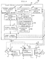
- the steam turbine activation controller 21 includes constituent elements such as a life consumption amount calculator 22, a life consumption amount storage device 23, a thermal stress limit update timing determining device 24, an accumulated life consumption amount calculator 25, a planned life consumption amount setting device 26, a thermal stress limit calculator 27, and a plant command value calculator 28.
- the constituent elements are described below.
- the life consumption amount calculator 22 calculates life consumption amounts (turbine rotor life consumption amounts) LC of the turbine rotor for one time of the activation.
- a temperature distribution in a radius direction of the turbine rotor is calculated by calculation of heat transfer to the turbine rotor based on the pressure of the steam 8 flowing in the main steam pipe, which is measured by the pressure indicator 12 and the temperature of the metal arranged at the initial stage of the steam turbine 3, which is measured by the thermometer 13.
- thermal stress of the turbine rotor is calculated by material mechanics calculation using a linear expansion coefficient, a Young's modulus, a Poisson ratio and the like of the turbine rotor.
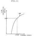
- FIG. 11 is a diagram illustrating a relationship between the thermal stress generated in the turbine rotor and a life consumption amount of the turbine rotor. As illustrated in FIG.
- the life consumption amount of the turbine rotor is a function of the peak value ⁇ max of the thermal stress generated during one cycle from the start of the activation of the steam turbine to the stop of an operation of the steam turbine.
- the thermal stress of the turbine rotor is calculated at predetermined calculation intervals based on the temperature and pressure (measured data 16) of the steam flowing in the steam turbine 3, the peak value (maximum value) ⁇ max during the cycle from the start of the activation of the steam turbine 3 to the stop of the operation is calculated, and thus the life consumption amounts LC of the turbine rotor for one time of the activation are calculated from the function illustrated in FIG. 11 .
- the function of the peak value ⁇ max is stored in a storage region (not illustrated) of the life consumption amount calculator 22, the life consumption amounts LC can be calculated from the peak value ⁇ max of the thermal stress based on the function read from the storage region.
- the life consumption amount storage device 23 stores, in a storage device such as a hard disk, the life consumption amounts LC of the turbine rotor for one time of the activation, which is calculated by the life consumption amount calculator 22.
- the thermal stress limit update timing determining device 24 determines timings when the thermal stress limits are updated.
- the update timings are, for example, timings when periodic inspection is performed after a certain time period in which an operation is performed.
- a time period from a previous update time when the thermal stress limits are previously updated to a current update time when the thermal stress limits are updated is referred to as a previous time period, while a time period from the current update time when the thermal stress limits are updated to a next update time when the thermal stress limits are next updated is referred to as a current time period.
- the thermal stress limit update timing determining device 24 has a timer (not illustrated) for measuring time.
- the thermal stress limit update timing determining device 24 switches the previous time period to the current time period.
- the present embodiment assumes that the current time period is equal to the previous time period.
- the accumulated life consumption amount calculator 25 accumulates, for each of the activation modes or for the hot start, the warm start, and the cold start respectively, a life consumption amount LC belonging to the previous time period based on the life consumption amounts LC for one time of the activation, which is stored in the life consumption amount storage device 23 at the timings determined by the thermal stress limit update timing determining device 24.
- the accumulated life consumption amount calculator 25 further calculates accumulated life consumption amounts (accumulated life consumption amounts of the turbine rotor) of the turbine rotor for the previous time period.
- the planned life consumption amount setting device 26 estimates, based on the accumulated life consumption amounts of the turbine rotor for the previous period, the numbers of times of the activation for one year in each of the activation modes and planned life consumption amounts for the numbers of years of a plant operation in the activation modes and sets planned life consumption amounts LCO (planned life consumption amounts of the turbine rotor) in one operation for the current time period in each of the activation modes, when a plant operation plan is created. Details of the planned life consumption amount setting device 26 are described later with reference to FIGs. 2 to 4 .
- the thermal stress limit calculator 27 calculates, based on the planned life consumption amount LCO of the turbine rotor for the current time period, the thermal stress limit of the turbine rotor in each of the activation modes and updates the thermal stress limit in each of the activation modes.
- the thermal stress limit in each of the activation modes is determined so that the life consumption amount of the turbine rotor for one time of the activation does not exceed the planned life consumption amount or LC ⁇ LCO.
- the thermal stress limit is calculated by calculating value ⁇ max0 corresponding to the planned life consumption amount LCO based on a thermal stress-life consumption amount curve 300 (refer to FIG. 11 ).
- the plant command value calculator 28 determines the plant command values 17 based on the measured data 16 and outputs the plant command values 17 to the heat source medium amount adjuster 14 and the main steam adjusting valve 15 respectively.
- the plant command values 17 are the command value (heat source medium adjustment command value) to be used to adjust the heat source medium and the command value (main steam adjustment command value) to be used to adjust the amount of the steam 8.
- Operational amounts (valve opening degrees in the present embodiment) of the heat source medium amount adjuster 14 and the main steam adjusting valve 15 are adjusted by PID for example, control based on the heat source medium adjustment command value and the main steam adjustment command value, for example.
- the plant command value calculator 28 includes a low value selector (not illustrated).
- the low value selector selects smaller value which is either one of the command value calculated based on the measured data 16 and the thermal stress limit input from the thermal stress limit calculator 27, as the plant command value 17.
- the thermal stress of the turbine rotor is suppressed to a value equal to or lower than the thermal stress limits set by the thermal stress limit calculator 27.
- FIG. 2 is a detailed block diagram illustrating the planned life consumption amount setting device 26.
- the planned life consumption amount setting device 26 includes a life consumption amount deviation calculator 29 and a planned life consumption amount calculator 30.
- the calculators 29 and 30 are described below.
- the life consumption amount deviation calculator 29 calculates deviation of the life consumption amounts in each of the activation modes based on the accumulated life consumption amounts of the turbine rotor for the previous time period in each of the activation modes, which are calculated by the accumulated life consumption amount calculator 25.
- the deviation of the life consumption amounts is calculated by subtracting the accumulated life consumption amount from the planned life consumption amount for the previous period.
- the planned life consumption amount calculator 30 calculates planned life consumption amounts for the current time period in each of the activation modes based on the deviation of the life consumption amounts.
- the planned life consumption amount for the current time period is calculated by adding the deviation of the life consumption amount to the planned life consumption amount for the previous time period.
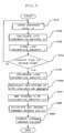
- the measured data 16 is input to the life consumption amount calculator 22 (in S101).
- the life consumption amount calculator 22 calculates the life consumption amount LC of the turbine rotor for one time of the activation based on the input measured data 16 (in S102) and outputs the calculated life consumption amount LC to the life consumption amount storage device 23.
- the life consumption amount storage device 23 stores the input life consumption amount LC of the turbine rotor for one time of the activation in the storage device such as the hard disk (in S103).
- the thermal stress limit update timing determining device 24 determines whether or not the current time reaches the time when the thermal stress limits are updated (in S104).
- the thermal stress limit update timing determining device 24 outputs a signal to the accumulated life consumption amount calculator 25 (in S104). If the current time does not reach the time when the thermal stress limits are updated, the procedure returns to S101 and the processes of S101 to S103 are performed again.
- the accumulated life consumption amount calculator 25 accumulates the life consumption amounts LC belonging to the previous time period in each of the activation modes based on the life consumption amounts LC of the turbine rotor for one time of the activation, which are stored in the life consumption amount storage device 23, and calculates the accumulated life consumption amounts of the turbine rotor for the previous time period (in S105). Then, the accumulated life consumption amount calculator 25 outputs the calculated life consumption amounts to the life consumption amount deviation calculator 29 of the planned life consumption amount setting device 26.
- the life consumption amount deviation calculator 29 calculates deviations of the life consumption amounts in each of the activation modes based on the accumulated life consumption amounts of the turbine rotor for the previous time period in each of the activation modes, which are calculated by the accumulated life consumption amount calculator 25 (in S106) and outputs the calculated deviations to the planned life consumption amount calculator 30.
- the planned life consumption amount calculator 30 calculates planned life consumption amounts for the current time period in the activation modes (in S107) based on the deviations of the life consumption amounts and outputs the calculated planned life consumption amounts to the thermal stress limit calculator 27.
- the thermal stress limit calculator 27 calculates the thermal stress limit of the turbine rotor for each of the activation modes based on the input planned life consumption amount LCO of the turbine rotor for the current time period and updates the thermal stress limit (in S108). Then, the thermal stress limit calculator 27 outputs the thermal stress limits to the plant command value calculator 28 (in S109). Then, the procedure illustrated in FIG. 3 is terminated.
- the steam turbine activation controller 21 repeatedly performs the aforementioned procedure during an operation of the steam turbine power plant 100.
- the plant command value calculator 28 calculates the command values based on the measured data 16 and compares the command values with the thermal stress limits received from the thermal stress limit calculator 27.
- the plant command value calculator 28 further outputs a smaller value which is either one of the command value and the thermal stress limit to the heat source medium amount adjuster 14, and outputs a smaller value which is either one of the command value and the thermal stress limit to the main steam adjusting valve 15.
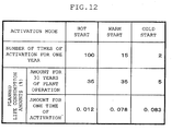
- FIG. 12 is a diagram illustrating an example of general setting of planned life consumption amounts for one operation in each of the activation modes in a plant operation plan.
- the example illustrated in FIG. 12 assumes that the numbers of times of the activation for one year in the hot start, the warm start, and the cold start are 100, 15, and 2 respectively.
- the example illustrated in FIG. 12 assumes that planned life consumption amounts in the activation modes for 30 years of a plant operation are 35%, 35%, and 5%.
- the example illustrated in FIG. 12 assumes that the planned life consumption amounts LCO in the activation modes are set to 0.012%, 0.078%, and 0.083%.
- the limits for the thermal stress to be applied upon activation control are determined so that the life consumption amounts of the turbine rotor for one time of the activation in the activation modes do not exceed 0.012%, 0.078%, and 0.083%. In this manner, the limits that are set upon the plan without consideration of operational results of the plant have been normally used for years (30 years in this case) of the plant operation.
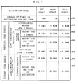
- FIG. 4 is a diagram illustrating an example in which planned consumption amounts for the current time period in each of the activation modes are set by the planned life consumption amount setting device 26.
- a second row represents the numbers 50 of times of the activation for one year
- a third row represents accumulated life consumption amounts 51 for the previous time period
- a fourth row represents planned life consumption amounts 52 for the previous time period
- a fifth row represents planned life consumption amounts 53 for one time of the activation for the previous time period
- a sixth row represents deviations 54 of the life consumption amounts for the previous time period
- a seventh row represents planned life consumption amounts 55 for the current time period
- an eighth row represents planned life consumption amounts 56 for one time of the activation for the current time period.
- the deviations 54 of the life consumption amounts for the previous time period are obtained by subtracting the accumulated life consumption amounts 51 for the previous time period from the planned life consumption amounts 52 for the previous time period.
- the planned life consumption amounts 55 for the previous time period are obtained by adding the deviations 54 of the life consumption amounts for the previous time period to the planned life consumption amounts 52 for the previous time period.
- the planned life consumption amounts 53 for one time of the activation for the previous time period are calculated by dividing the planned life consumption amounts 52 for the previous time period by the numbers of times of the activation in 2 years in each of the activation modes
- the planned life consumption amounts 56 for one time of the activation for the current time period are calculated by dividing the planned life consumption amounts 55 for the current time period by the numbers of times of the activation in 2 years in each of the activation modes.
- the deviations of the life consumption amounts are positive and the planned life consumption amounts for the current time period are larger than the planned life consumption amounts for the previous time period.
- the deviation of the life consumption amount is negative and the planned life consumption amount for the current time period is smaller than the planned life consumption amount for the previous time period.
- the planned life consumption amounts 53 for one time of the activation for the previous time period are compared with the planned life consumption amounts 56 for one time of the activation for the current time period, the planned life consumption amounts 56 for one time of the activation for the current time period are larger than the planned life consumption amounts 53 for one time of the activation for the previous time period in the hot start and the warm start. If a planned life consumption amount for one time of the activation is increased, an interested thermal stress limit of the turbine rotor is increased based on the thermal stress-life consumption amount curve 300 illustrated in FIG. 11 and the plant can be activated at a higher speed.
- the planned life consumption amount 56 for one time of the activation for the current time period is smaller than the planned life consumption amount 53 for one time of the activation for the previous time period in the cold start, and the thermal stress limit of the turbine rotor is reduced, it requires much time necessary for activating the plant.
- the life consumption amount in the cold start can be suppressed.
- an interested thermal stress limit of the turbine rotor can be set to a large value by adding a deviation (serving as a margin) of the planned life consumption amount from the accumulated life consumption amount to a planned life consumption amount to be next used, and the plant can be activated at a high speed.
- the thermal stress limit of the turbine rotor can be set to a small value by subtracting the deviation from the planned life consumption amount to be next used, and the plant can be activated while suppressing the life consumption amount.
- the plant can be safely activated at a high speed while maintaining the thermal stress at a level equal to or lower than a limit in consideration of operational results of the plant.
- FIG. 5 is a schematic diagram illustrating a configuration of a steam turbine power plant 101 according to a second embodiment. Parts that are the same as or similar to those in the first embodiment are represented by the same reference numerals as those in the first embodiment in FIG. 5 , and a description thereof is omitted.
- the second embodiment is different from the first embodiment in that planned life consumption amounts for the current time period are set while the activation modes are weighted.
- the steam turbine activation controller 21 further includes a life consumption amount deviation assignment ratio input device 110.
- a planned life consumption amount setting device 126 receives values output from the accumulated life consumption amount calculator 25 and values output from the life consumption amount deviation assignment ratio input device 110.
- the life consumption amount deviation assignment ratio input device 110 and the planned life consumption amount setting device 126 are described below.
- the life consumption amount deviation assignment ratio input device 110 stores an assignment ratio of deviation of life consumption amounts to each of the activation modes.
- the assignment ratio of the deviation of the life consumption amounts is a set value input by an operator based on an operational state or the like.
- the life consumption amount to be assigned to each of the activation modes is changed by the set value. Specifically, weighting for each of the activation modes can be performed by setting the assignment ratio.
- FIG. 6 is a block diagram illustrating the planned life consumption amount setting device 126.
- the planned life consumption amount setting device 126 includes the life consumption amount deviation calculator 29, a life consumption amount deviation assignment value calculator 111 and a planned life consumption amount calculator 130.
- the planned life consumption amount calculator 130 calculates planned life consumption amounts for the current time period in each of the activation modes based on values output from the life consumption amount deviation assignment value calculator 111 (as described later).
- the life consumption amount deviation assignment value calculator 111 of the planned life consumption amount setting device 126 calculates life consumption amount deviation assignment values for each of the activation modes based on deviations of life consumption amounts for the previous time period, which are output from the planned life consumption amount calculator 29 and the assignment ratios (assignment ratios of deviation of life consumption amounts of the turbine rotor) received from the life consumption amount deviation assignment ratio input device 110. Then, the life consumption amount deviation assignment value calculator 111 outputs, to the planned life consumption amount calculator 130, the life consumption amount deviation assignment values.
- the life consumption amount deviation assignment values DLC_i are calculated according to the following Equations.
- ⁇ _ T ⁇ _ 1 + ⁇ _ 2 + ⁇ _ 3
- LCMG _ T MAX LCMG _ 1, 0 + MAX LCMG_2, 0 + MAX LCMG_3, 0
- DLC _ i MIN LCMG_i, 0 + LCMG _ T ⁇ ⁇ _ i / ⁇ _ T
- the planned life consumption amount calculator 130 calculates planned life consumption amounts for the current time period in each of the activation modes based on the life consumption amount deviation assignment values and the like, received from the life consumption amount deviation assignment value calculator 111. Then, the planned life consumption amount calculator 130 outputs the planned life consumption amounts to the thermal stress limit calculator 27. The planned life consumption amounts for the current time period are calculated by adding the life consumption amount deviation assignment values to the planned life consumption amounts for the previous time period.
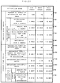
- FIG. 7 is a diagram illustrating an example of the planned life consumption amounts calculated for the current time period in each of the activation modes and set by the planed life consumption amount setting device 126.
- a seventh row represents ratios 150 of assigning the deviations of the life consumption amounts to each of the activation modes
- an eighth row represents life consumption amount deviation assignment values 151.
- the other rows illustrated in FIG. 7 are the same as FIG. 4 .
- the life consumption amount deviation assignment values 151 are calculated by the life consumption amount deviation assignment value calculator 111 according to Equations 160 to 162 based on the deviations 54 of the life consumption amounts for the previous time period and the ratios 150 of assigning the deviations of the life consumption amounts.
- the planned life consumption amounts 55 for the current time period are obtained by adding the life consumption amount deviation assignment values 151 to the planned life consumption amounts 52 for the previous time period.
- the assignment ratios of deviation to the hot start, the warm start, and the cold start are 0, 1, and 0 or all the deviations of the life consumption amounts for the previous time period are assigned to the warm start for the current time period.
- the planned life consumption amount 56 for one time of the activation for the current time period in the warm start is increased.
- the thermal stress limit of the turbine rotor in the warm start increases and the plant can be activated at a high speed.
- the planned life consumption amount 56 for one time of the activation for the current time period in the hot start is reduced, compared with the example illustrated in FIG. 4 , and is equal to the planned life consumption amount 53 for one time of the activation for the previous time period in the example illustrated in FIG. 7 .
- the thermal stress limit of the turbine rotor in the hot start is equal to the thermal stress limit of the turbine rotor for the previous time period, and an activation time of the plant in the hot start does not change.
- the effects obtained in the first embodiment and the following effects can be obtained by the aforementioned configuration.
- the assignment ratios of the deviation to each of the activation modes are input, and the planned life consumption amounts for the current time period are determined based on the life consumption amount deviation assignment values calculated based on the assignment ratios of the deviation.
- the plant can be safely activated at a high speed while providing priorities to the activation modes and maintaining the thermal stress at a level equal to or lower than a limit in consideration of operational results of the plant.
- FIG. 8 is a schematic diagram illustrating a steam turbine power plant 102 according to a third embodiment. Parts that are the same as or similar to those in the second embodiment are represented by the same reference numerals as those in the second embodiment in FIG. 8 , and a description thereof is omitted.
- the third embodiment is different from the second embodiment in that the numbers of times of the activation per year for the current time period are identified and planned life consumption amounts for the current time period are set.
- the steam turbine activation controller 21 further includes an activation number input device 200, and a planned life consumption amount setting device 226 receives values output from the activation number input device 200 as well as from the accumulated life consumption amount calculator 25 and from the life consumption amount deviation assignment ratio input device 110.
- the activation number input device 200 and the planned life consumption amount setting device 226 are described below.
- the activation number input device 200 stores planned number of times of the activation per year for the current time period in each of the activation modes.
- the numbers are values input and set by the operator.
- FIG. 9 is a block diagram illustrating the planned life consumption amount setting device 226.
- the planned life consumption amount setting device 26 includes a life consumption amount deviation calculator 229, a life consumption amount deviation assignment value calculator 201, and a planned life consumption amount calculator 130.
- the life consumption amount deviation calculator 229 calculates deviation of life consumption amounts in each of the activation modes.
- the life consumption amount deviation assignment value calculator 201 calculates life consumption amount deviation assignment value to be assigned to each of the activation modes.
- the life consumption amount deviation calculator 229 calculates deviation of the life consumption amounts in each of the activation modes based on accumulated life consumption amounts of the turbine rotor for the previous time period, which are calculated for each of the activation modes by the accumulated life consumption amount calculator 25, and on the number of times of the activation per year for the current time period in each of the activation modes, which is received from the activation number input device 200.
- the life consumption amount deviation calculator 229 outputs the deviations of the life consumption amounts to the life consumption amount deviation assignment value calculator 201.
- the deviations of the life consumption amounts for the previous time period are calculated by subtracting the accumulated life consumption amounts from the planned life consumption amounts for the previous time period.
- deviation LCMGS_i of the life consumption amounts is produced by the fact that the number NSC_i of times of the activation per year for the current time period is reduced to be smaller than the number NSC_i of times of the activation per year for the previous time period.
- the deviation LCMGS_i is calculated according to the following Equation using planned life consumption amounts LCO_i for the previous time period.
- LCMGS _ i LC0_i ⁇ MAX NSP _ i ⁇ NSC_i, 0 / NSP _ i
- the life consumption amount assignment value calculator 201 calculates life consumption amount deviation assignment value to be assigned to each of the activation modes, based on the deviation, output from the life consumption amount deviation calculator 229, of the life consumption amounts for the previous time period and the assignment ratio received from the life consumption amount deviation assignment ratio input device 110.
- Equation 262 ⁇ _T and LCMG_T are items calculated in Equations 160 and 161, respectively.
- FIG. 10 is a diagram illustrating an example of planned life consumption amounts calculated for the current time period in each of the activation modes and set by the planned life consumption amount setting device 226.
- a seventh row represents the number 250 of times of the activation per year for the current time period
- an eighth row represents deviation 252 of the life consumption amounts, which is produced by reducing the number of times of the activation
- a tenth row represents life consumption amount deviation assignment value 251.
- Other parts are the same as those in FIG. 7 .
- the deviation 252 of the life consumption amounts are calculated according to Equation 260 based on the number 50 of times of the activation per year for the previous time period, the number 250 of times of the activation per year for the current time period, and the planned life consumption amounts 52 for the previous time period.
- the life consumption amount deviation assignment value 251 is calculated according to Equations 160, 161, 261, and 262 based on the deviation 54 of the life consumption amounts for the previous time period, the deviation 252 of the life consumption amounts, which is produced by reducing the number of times of the activation, and the ratio 150 of assigning the deviation of the life consumption amounts.
- the planned life consumption amount 55 for the current time period is obtained by adding the life consumption amount deviation assignment value 251 to the planned life consumption amount 52 for the previous time period.
- the number of times of the activation per year in the hot start is changed from 100 to 80, and the number of times of the activation per year in the warm start is changed from 15 to 30.
- the life consumption amount for one time of the activation is reduced, which is due to the increase in the number of times of the activation in the warm start, the deviation of the life consumption amount for the previous time period and the deviation of the life consumption amounts, which is produced by reducing the number of times of the activation in the hot start, are assigned to the warm start for the current time period.
- the planned life consumption amount 56 for one time of the activation for the current time period in the warm start further is further increased.
- the thermal stress limit of the turbine rotor in the warm start is increased, and the plant can be activated at a high speed.
- the effects obtained in the first and second embodiments and the following effects can be obtained by the aforementioned configuration.
- the deviation of the life consumption amounts which is produced by changing the number of times of the activation per year, is reflected in the planned life consumption amounts for the current time period.
- the plant can be safely activated at a high speed while identifying the numbers of times of the activation per year for the current time period, providing priorities to the activation modes, and maintaining the thermal stress at a level equal to or lower than a limit in consideration of operational results of the plant.
- the present invention is not limited to the aforementioned embodiments, but covers various modifications. While, for illustrative purposes, those embodiments have been described specifically, the present invention is not necessarily limited to the specific forms disclosed. Thus, partial replacement is possible between the components of a certain embodiment and the components of another. Likewise, certain components can be added to or removed from the embodiments disclosed.
- the thermal stress limit update timing determining device 24 sets times when the thermal stress limits are updated to the times when the periodic inspection is performed after the certain time period in which the operation is performed.
- the essential effect of the invention is the fact that the plant is safely activated at a high speed while maintaining the thermal stress at a level equal to or lower than a limit in consideration of operational results of the plant.
- the times when the thermal stress limits are updated are not limited as long as the essential effect is obtained.
- the timing at which the thermal stress limits are updated may be a timing at which an accumulated life consumption amount of the turbine rotor from the previous update timing at which the thermal stress limits are updated exceeds a set value.
- the times when the thermal stress limits are updated may be the times when the periodic inspection is performed after the certain time period in which the operation is performed and the times when an accumulated life consumption amount of the turbine rotor from the previous update time when the thermal stress limits are updated exceeds the set value.
- each of the embodiments describes the case where the invention is applied to the combined cycle power plant as an example.
- the invention is not limited to the combined cycle power plant and is applicable to all power plants each including a steam turbine and typified by a steam power plant and a solar power plant.
- a procedure for activating the plant is the same as or similar to the procedure for activating the combined cycle power plant.
- coal or natural gas may be used as the heat source medium 5
- air or oxygen may be used as the low-temperature fluid
- a fuel adjusting valve may be used as the heat source medium adjuster 14
- a furnace included in a boiler may be used as the heat source device 1
- combustion gas may be used as the high-temperature fluid
- a heat transfer unit (steam generator) included in the boiler may be used as the steam generator 2.
- sunlight may be used as the heat source medium 5
- a device for driving a heat collecting panel may be used as the heat source medium adjuster 14
- the heat collecting panel may be used as the heat source device 1
- media such as oil and high-temperature solvent salt, which convert solar thermal energy and hold the converted energy, may be used as the low-temperature fluid and the high-temperature fluid.
Landscapes
- Engineering & Computer Science (AREA)
- Chemical & Material Sciences (AREA)
- Combustion & Propulsion (AREA)
- Mechanical Engineering (AREA)
- General Engineering & Computer Science (AREA)
- Physics & Mathematics (AREA)
- Thermal Sciences (AREA)
- Control Of Turbines (AREA)
Applications Claiming Priority (1)
| Application Number | Priority Date | Filing Date | Title |
|---|---|---|---|
| JP2013229571A JP6245738B2 (ja) | 2013-11-05 | 2013-11-05 | 蒸気タービンの起動制御装置及び起動方法 |
Publications (2)
| Publication Number | Publication Date |
|---|---|
| EP2871334A1 EP2871334A1 (en) | 2015-05-13 |
| EP2871334B1 true EP2871334B1 (en) | 2018-06-06 |
Family
ID=51868057
Family Applications (1)
| Application Number | Title | Priority Date | Filing Date |
|---|---|---|---|
| EP14191921.7A Active EP2871334B1 (en) | 2013-11-05 | 2014-11-05 | Steam turbine power plant and method for activating steam turbine power plant |
Country Status (4)
| Country | Link |
|---|---|
| US (1) | US9863283B2 (enExample) |
| EP (1) | EP2871334B1 (enExample) |
| JP (1) | JP6245738B2 (enExample) |
| CN (1) | CN104612762B (enExample) |
Families Citing this family (10)
| Publication number | Priority date | Publication date | Assignee | Title |
|---|---|---|---|---|
| FR3015672B1 (fr) * | 2013-12-23 | 2016-02-05 | Ge Energy Products France Snc | Systeme et procede de test d'une machine tournante |
| US9632011B2 (en) | 2013-12-23 | 2017-04-25 | General Electric Company | System and method for testing a gas turbine |
| JP2017014971A (ja) * | 2015-06-30 | 2017-01-19 | 三菱日立パワーシステムズ株式会社 | 太陽熱発電システム及び太陽熱発電方法 |
| JP6498059B2 (ja) * | 2015-06-30 | 2019-04-10 | 三菱日立パワーシステムズ株式会社 | 起動制御装置 |
| JP6510923B2 (ja) * | 2015-07-23 | 2019-05-08 | 三菱日立パワーシステムズ株式会社 | 発電プラントの起動制御装置及び起動制御方法 |
| US10100679B2 (en) * | 2015-08-28 | 2018-10-16 | General Electric Company | Control system for managing steam turbine rotor stress and method of use |
| JP6710039B2 (ja) | 2015-10-28 | 2020-06-17 | 三菱日立パワーシステムズ株式会社 | 計画装置、計画方法およびプログラム |
| KR101842370B1 (ko) * | 2016-12-05 | 2018-03-26 | 두산중공업 주식회사 | 복합화력발전소의 빠른 기동 제어 방법 및 시스템 |
| CN110985142B (zh) * | 2019-12-16 | 2022-07-19 | 上海电气电站设备有限公司 | 汽轮机启停智能辅助系统及温控方法 |
| US11352901B2 (en) * | 2020-02-17 | 2022-06-07 | Emerson Process Management Power & Water Solutions | Methods and apparatus to determine material parameters of turbine rotors |
Family Cites Families (9)
| Publication number | Priority date | Publication date | Assignee | Title |
|---|---|---|---|---|
| GB2002543B (en) | 1977-07-29 | 1982-02-17 | Hitachi Ltd | Rotor-stress preestimating turbine control system |
| JPS61205309A (ja) | 1985-03-08 | 1986-09-11 | Hitachi Ltd | 給水加熱器の保護運転方法及びその装置 |
| JP2677787B2 (ja) * | 1986-11-06 | 1997-11-17 | バブコツク日立株式会社 | ボイラ制御装置 |
| US4888953A (en) * | 1987-11-13 | 1989-12-26 | Babcock-Hitachi Kabushiki Kaisha | Apparatus for controlling boiler/turbine plant |
| JPH0586808A (ja) * | 1991-09-27 | 1993-04-06 | Hitachi Ltd | タービンの起動停止パターン設定方法 |
| JP3111789B2 (ja) * | 1994-02-02 | 2000-11-27 | 富士電機株式会社 | タービンの寿命消費監視装置及びロータの寿命消費監視方法 |
| AU752024B2 (en) * | 2000-04-14 | 2002-09-05 | Kabushiki Kaisha Toshiba | Method and equipment for assessing the life of members put under high in-service temperature environment for long period |
| JP2009281248A (ja) | 2008-05-21 | 2009-12-03 | Toshiba Corp | タービンシステムおよびタービンシステム起動制御方法 |
| US9080765B2 (en) * | 2011-08-22 | 2015-07-14 | General Electric Company | Systems and methods for heat recovery steam generation optimization |
-
2013
- 2013-11-05 JP JP2013229571A patent/JP6245738B2/ja active Active
-
2014
- 2014-11-04 US US14/532,253 patent/US9863283B2/en active Active
- 2014-11-04 CN CN201410613010.2A patent/CN104612762B/zh active Active
- 2014-11-05 EP EP14191921.7A patent/EP2871334B1/en active Active
Also Published As
| Publication number | Publication date |
|---|---|
| US20150121872A1 (en) | 2015-05-07 |
| CN104612762B (zh) | 2016-10-05 |
| EP2871334A1 (en) | 2015-05-13 |
| CN104612762A (zh) | 2015-05-13 |
| US9863283B2 (en) | 2018-01-09 |
| JP6245738B2 (ja) | 2017-12-13 |
| JP2015090091A (ja) | 2015-05-11 |
Similar Documents
| Publication | Publication Date | Title |
|---|---|---|
| EP2871334B1 (en) | Steam turbine power plant and method for activating steam turbine power plant | |
| EP2871333B1 (en) | Activation control device | |
| EP2792858B1 (en) | Steam turbine power plant | |
| US9255494B2 (en) | Steam turbine power plant | |
| EP3118426B1 (en) | Activation control apparatus | |
| CN102183890B (zh) | 协调控制系统调节器参数优化整定方法 | |
| JP6180896B2 (ja) | 発電プラントの起動制御装置及び起動制御方法 | |
| CN118920610B (zh) | 二次再热机组快速响应电网需求的控制方法及系统 | |
| CN117280167A (zh) | 用于控制连接到地热源以向至少一个建筑物提供热能的装置的方法、装置和与该装置相关的调节系统 | |
| CN103233787A (zh) | 节流调节型汽轮机转子热应力预估方法 | |
| EP3121392B1 (en) | Start-up control device and start-up control method for power plant | |
| EP2876267B1 (en) | Activation control device | |
| JP4234414B2 (ja) | 用役システムの制御方法 | |
| US9249682B2 (en) | Steam turbine power plant |
Legal Events
| Date | Code | Title | Description |
|---|---|---|---|
| PUAI | Public reference made under article 153(3) epc to a published international application that has entered the european phase |
Free format text: ORIGINAL CODE: 0009012 |
|
| 17P | Request for examination filed |
Effective date: 20141219 |
|
| AK | Designated contracting states |
Kind code of ref document: A1 Designated state(s): AL AT BE BG CH CY CZ DE DK EE ES FI FR GB GR HR HU IE IS IT LI LT LU LV MC MK MT NL NO PL PT RO RS SE SI SK SM TR |
|
| AX | Request for extension of the european patent |
Extension state: BA ME |
|
| RIN1 | Information on inventor provided before grant (corrected) |
Inventor name: KAWATA, MIYUKI Inventor name: NOMURA, KENICHIRO Inventor name: KATAGIRI, YUKINORI Inventor name: KIM, EUNKYEONG Inventor name: YOSHIDA, TAKUYA Inventor name: YASHIKI, TATSURO Inventor name: SUZUKI, FUMIYUKI Inventor name: YOSHIDA, YASUHIRO Inventor name: YAMANAKA, KAZUNORI Inventor name: IYANAGA, NORIHIRO |
|
| GRAP | Despatch of communication of intention to grant a patent |
Free format text: ORIGINAL CODE: EPIDOSNIGR1 |
|
| STAA | Information on the status of an ep patent application or granted ep patent |
Free format text: STATUS: GRANT OF PATENT IS INTENDED |
|
| INTG | Intention to grant announced |
Effective date: 20171215 |
|
| GRAS | Grant fee paid |
Free format text: ORIGINAL CODE: EPIDOSNIGR3 |
|
| GRAA | (expected) grant |
Free format text: ORIGINAL CODE: 0009210 |
|
| STAA | Information on the status of an ep patent application or granted ep patent |
Free format text: STATUS: THE PATENT HAS BEEN GRANTED |
|
| AK | Designated contracting states |
Kind code of ref document: B1 Designated state(s): AL AT BE BG CH CY CZ DE DK EE ES FI FR GB GR HR HU IE IS IT LI LT LU LV MC MK MT NL NO PL PT RO RS SE SI SK SM TR |
|
| REG | Reference to a national code |
Ref country code: GB Ref legal event code: FG4D |
|
| REG | Reference to a national code |
Ref country code: CH Ref legal event code: EP Ref country code: AT Ref legal event code: REF Ref document number: 1006320 Country of ref document: AT Kind code of ref document: T Effective date: 20180615 |
|
| REG | Reference to a national code |
Ref country code: IE Ref legal event code: FG4D |
|
| REG | Reference to a national code |
Ref country code: DE Ref legal event code: R096 Ref document number: 602014026586 Country of ref document: DE |
|
| REG | Reference to a national code |
Ref country code: NL Ref legal event code: MP Effective date: 20180606 |
|
| REG | Reference to a national code |
Ref country code: LT Ref legal event code: MG4D |
|
| PG25 | Lapsed in a contracting state [announced via postgrant information from national office to epo] |
Ref country code: ES Free format text: LAPSE BECAUSE OF FAILURE TO SUBMIT A TRANSLATION OF THE DESCRIPTION OR TO PAY THE FEE WITHIN THE PRESCRIBED TIME-LIMIT Effective date: 20180606 Ref country code: SE Free format text: LAPSE BECAUSE OF FAILURE TO SUBMIT A TRANSLATION OF THE DESCRIPTION OR TO PAY THE FEE WITHIN THE PRESCRIBED TIME-LIMIT Effective date: 20180606 Ref country code: CY Free format text: LAPSE BECAUSE OF FAILURE TO SUBMIT A TRANSLATION OF THE DESCRIPTION OR TO PAY THE FEE WITHIN THE PRESCRIBED TIME-LIMIT Effective date: 20180606 Ref country code: FI Free format text: LAPSE BECAUSE OF FAILURE TO SUBMIT A TRANSLATION OF THE DESCRIPTION OR TO PAY THE FEE WITHIN THE PRESCRIBED TIME-LIMIT Effective date: 20180606 Ref country code: BG Free format text: LAPSE BECAUSE OF FAILURE TO SUBMIT A TRANSLATION OF THE DESCRIPTION OR TO PAY THE FEE WITHIN THE PRESCRIBED TIME-LIMIT Effective date: 20180906 Ref country code: NO Free format text: LAPSE BECAUSE OF FAILURE TO SUBMIT A TRANSLATION OF THE DESCRIPTION OR TO PAY THE FEE WITHIN THE PRESCRIBED TIME-LIMIT Effective date: 20180906 Ref country code: LT Free format text: LAPSE BECAUSE OF FAILURE TO SUBMIT A TRANSLATION OF THE DESCRIPTION OR TO PAY THE FEE WITHIN THE PRESCRIBED TIME-LIMIT Effective date: 20180606 |
|
| PG25 | Lapsed in a contracting state [announced via postgrant information from national office to epo] |
Ref country code: GR Free format text: LAPSE BECAUSE OF FAILURE TO SUBMIT A TRANSLATION OF THE DESCRIPTION OR TO PAY THE FEE WITHIN THE PRESCRIBED TIME-LIMIT Effective date: 20180907 Ref country code: HR Free format text: LAPSE BECAUSE OF FAILURE TO SUBMIT A TRANSLATION OF THE DESCRIPTION OR TO PAY THE FEE WITHIN THE PRESCRIBED TIME-LIMIT Effective date: 20180606 Ref country code: LV Free format text: LAPSE BECAUSE OF FAILURE TO SUBMIT A TRANSLATION OF THE DESCRIPTION OR TO PAY THE FEE WITHIN THE PRESCRIBED TIME-LIMIT Effective date: 20180606 Ref country code: RS Free format text: LAPSE BECAUSE OF FAILURE TO SUBMIT A TRANSLATION OF THE DESCRIPTION OR TO PAY THE FEE WITHIN THE PRESCRIBED TIME-LIMIT Effective date: 20180606 |
|
| REG | Reference to a national code |
Ref country code: AT Ref legal event code: MK05 Ref document number: 1006320 Country of ref document: AT Kind code of ref document: T Effective date: 20180606 |
|
| PG25 | Lapsed in a contracting state [announced via postgrant information from national office to epo] |
Ref country code: NL Free format text: LAPSE BECAUSE OF FAILURE TO SUBMIT A TRANSLATION OF THE DESCRIPTION OR TO PAY THE FEE WITHIN THE PRESCRIBED TIME-LIMIT Effective date: 20180606 |
|
| PG25 | Lapsed in a contracting state [announced via postgrant information from national office to epo] |
Ref country code: RO Free format text: LAPSE BECAUSE OF FAILURE TO SUBMIT A TRANSLATION OF THE DESCRIPTION OR TO PAY THE FEE WITHIN THE PRESCRIBED TIME-LIMIT Effective date: 20180606 Ref country code: CZ Free format text: LAPSE BECAUSE OF FAILURE TO SUBMIT A TRANSLATION OF THE DESCRIPTION OR TO PAY THE FEE WITHIN THE PRESCRIBED TIME-LIMIT Effective date: 20180606 Ref country code: EE Free format text: LAPSE BECAUSE OF FAILURE TO SUBMIT A TRANSLATION OF THE DESCRIPTION OR TO PAY THE FEE WITHIN THE PRESCRIBED TIME-LIMIT Effective date: 20180606 Ref country code: IS Free format text: LAPSE BECAUSE OF FAILURE TO SUBMIT A TRANSLATION OF THE DESCRIPTION OR TO PAY THE FEE WITHIN THE PRESCRIBED TIME-LIMIT Effective date: 20181006 Ref country code: PL Free format text: LAPSE BECAUSE OF FAILURE TO SUBMIT A TRANSLATION OF THE DESCRIPTION OR TO PAY THE FEE WITHIN THE PRESCRIBED TIME-LIMIT Effective date: 20180606 Ref country code: AT Free format text: LAPSE BECAUSE OF FAILURE TO SUBMIT A TRANSLATION OF THE DESCRIPTION OR TO PAY THE FEE WITHIN THE PRESCRIBED TIME-LIMIT Effective date: 20180606 Ref country code: SK Free format text: LAPSE BECAUSE OF FAILURE TO SUBMIT A TRANSLATION OF THE DESCRIPTION OR TO PAY THE FEE WITHIN THE PRESCRIBED TIME-LIMIT Effective date: 20180606 |
|
| PG25 | Lapsed in a contracting state [announced via postgrant information from national office to epo] |
Ref country code: IT Free format text: LAPSE BECAUSE OF FAILURE TO SUBMIT A TRANSLATION OF THE DESCRIPTION OR TO PAY THE FEE WITHIN THE PRESCRIBED TIME-LIMIT Effective date: 20180606 Ref country code: SM Free format text: LAPSE BECAUSE OF FAILURE TO SUBMIT A TRANSLATION OF THE DESCRIPTION OR TO PAY THE FEE WITHIN THE PRESCRIBED TIME-LIMIT Effective date: 20180606 |
|
| REG | Reference to a national code |
Ref country code: DE Ref legal event code: R097 Ref document number: 602014026586 Country of ref document: DE |
|
| PLBE | No opposition filed within time limit |
Free format text: ORIGINAL CODE: 0009261 |
|
| STAA | Information on the status of an ep patent application or granted ep patent |
Free format text: STATUS: NO OPPOSITION FILED WITHIN TIME LIMIT |
|
| 26N | No opposition filed |
Effective date: 20190307 |
|
| PG25 | Lapsed in a contracting state [announced via postgrant information from national office to epo] |
Ref country code: SI Free format text: LAPSE BECAUSE OF FAILURE TO SUBMIT A TRANSLATION OF THE DESCRIPTION OR TO PAY THE FEE WITHIN THE PRESCRIBED TIME-LIMIT Effective date: 20180606 Ref country code: DK Free format text: LAPSE BECAUSE OF FAILURE TO SUBMIT A TRANSLATION OF THE DESCRIPTION OR TO PAY THE FEE WITHIN THE PRESCRIBED TIME-LIMIT Effective date: 20180606 |
|
| REG | Reference to a national code |
Ref country code: CH Ref legal event code: PL |
|
| GBPC | Gb: european patent ceased through non-payment of renewal fee |
Effective date: 20181105 |
|
| PG25 | Lapsed in a contracting state [announced via postgrant information from national office to epo] |
Ref country code: LU Free format text: LAPSE BECAUSE OF NON-PAYMENT OF DUE FEES Effective date: 20181105 Ref country code: MC Free format text: LAPSE BECAUSE OF FAILURE TO SUBMIT A TRANSLATION OF THE DESCRIPTION OR TO PAY THE FEE WITHIN THE PRESCRIBED TIME-LIMIT Effective date: 20180606 |
|
| REG | Reference to a national code |
Ref country code: BE Ref legal event code: MM Effective date: 20181130 |
|
| REG | Reference to a national code |
Ref country code: IE Ref legal event code: MM4A |
|
| PG25 | Lapsed in a contracting state [announced via postgrant information from national office to epo] |
Ref country code: LI Free format text: LAPSE BECAUSE OF NON-PAYMENT OF DUE FEES Effective date: 20181130 Ref country code: CH Free format text: LAPSE BECAUSE OF NON-PAYMENT OF DUE FEES Effective date: 20181130 |
|
| PG25 | Lapsed in a contracting state [announced via postgrant information from national office to epo] |
Ref country code: IE Free format text: LAPSE BECAUSE OF NON-PAYMENT OF DUE FEES Effective date: 20181105 Ref country code: FR Free format text: LAPSE BECAUSE OF NON-PAYMENT OF DUE FEES Effective date: 20181130 |
|
| PG25 | Lapsed in a contracting state [announced via postgrant information from national office to epo] |
Ref country code: BE Free format text: LAPSE BECAUSE OF NON-PAYMENT OF DUE FEES Effective date: 20181130 Ref country code: AL Free format text: LAPSE BECAUSE OF FAILURE TO SUBMIT A TRANSLATION OF THE DESCRIPTION OR TO PAY THE FEE WITHIN THE PRESCRIBED TIME-LIMIT Effective date: 20180606 |
|
| PG25 | Lapsed in a contracting state [announced via postgrant information from national office to epo] |
Ref country code: GB Free format text: LAPSE BECAUSE OF NON-PAYMENT OF DUE FEES Effective date: 20181105 |
|
| PG25 | Lapsed in a contracting state [announced via postgrant information from national office to epo] |
Ref country code: MT Free format text: LAPSE BECAUSE OF NON-PAYMENT OF DUE FEES Effective date: 20181105 |
|
| PG25 | Lapsed in a contracting state [announced via postgrant information from national office to epo] |
Ref country code: TR Free format text: LAPSE BECAUSE OF FAILURE TO SUBMIT A TRANSLATION OF THE DESCRIPTION OR TO PAY THE FEE WITHIN THE PRESCRIBED TIME-LIMIT Effective date: 20180606 |
|
| PG25 | Lapsed in a contracting state [announced via postgrant information from national office to epo] |
Ref country code: PT Free format text: LAPSE BECAUSE OF FAILURE TO SUBMIT A TRANSLATION OF THE DESCRIPTION OR TO PAY THE FEE WITHIN THE PRESCRIBED TIME-LIMIT Effective date: 20180606 |
|
| PG25 | Lapsed in a contracting state [announced via postgrant information from national office to epo] |
Ref country code: HU Free format text: LAPSE BECAUSE OF FAILURE TO SUBMIT A TRANSLATION OF THE DESCRIPTION OR TO PAY THE FEE WITHIN THE PRESCRIBED TIME-LIMIT; INVALID AB INITIO Effective date: 20141105 Ref country code: MK Free format text: LAPSE BECAUSE OF NON-PAYMENT OF DUE FEES Effective date: 20180606 |
|
| REG | Reference to a national code |
Ref country code: DE Ref legal event code: R082 Ref document number: 602014026586 Country of ref document: DE Representative=s name: MERH-IP MATIAS ERNY REICHL HOFFMANN PATENTANWA, DE Ref country code: DE Ref legal event code: R081 Ref document number: 602014026586 Country of ref document: DE Owner name: MITSUBISHI POWER, LTD., JP Free format text: FORMER OWNER: MITSUBISHI HITACHI POWER SYSTEMS, LTD., YOKOHAMA, JP |
|
| PGFP | Annual fee paid to national office [announced via postgrant information from national office to epo] |
Ref country code: DE Payment date: 20250930 Year of fee payment: 12 |