EP2871307B2 - Gangreserve für ein motorbetriebenes Schloss - Google Patents
Gangreserve für ein motorbetriebenes Schloss Download PDFInfo
- Publication number
- EP2871307B2 EP2871307B2 EP14191762.5A EP14191762A EP2871307B2 EP 2871307 B2 EP2871307 B2 EP 2871307B2 EP 14191762 A EP14191762 A EP 14191762A EP 2871307 B2 EP2871307 B2 EP 2871307B2
- Authority
- EP
- European Patent Office
- Prior art keywords
- lock
- motor
- energy
- slide
- voltage
- Prior art date
- Legal status (The legal status is an assumption and is not a legal conclusion. Google has not performed a legal analysis and makes no representation as to the accuracy of the status listed.)
- Active
Links
Images

Classifications
-
- E—FIXED CONSTRUCTIONS
- E05—LOCKS; KEYS; WINDOW OR DOOR FITTINGS; SAFES
- E05B—LOCKS; ACCESSORIES THEREFOR; HANDCUFFS
- E05B47/00—Operating or controlling locks or other fastening devices by electric or magnetic means
- E05B47/02—Movement of the bolt by electromagnetic means; Adaptation of locks, latches, or parts thereof, for movement of the bolt by electromagnetic means
- E05B47/026—Movement of the bolt by electromagnetic means; Adaptation of locks, latches, or parts thereof, for movement of the bolt by electromagnetic means the bolt moving rectilinearly
-
- E—FIXED CONSTRUCTIONS
- E05—LOCKS; KEYS; WINDOW OR DOOR FITTINGS; SAFES
- E05B—LOCKS; ACCESSORIES THEREFOR; HANDCUFFS
- E05B47/00—Operating or controlling locks or other fastening devices by electric or magnetic means
- E05B47/0001—Operating or controlling locks or other fastening devices by electric or magnetic means with electric actuators; Constructional features thereof
- E05B47/0012—Operating or controlling locks or other fastening devices by electric or magnetic means with electric actuators; Constructional features thereof with rotary electromotors
-
- E—FIXED CONSTRUCTIONS
- E05—LOCKS; KEYS; WINDOW OR DOOR FITTINGS; SAFES
- E05B—LOCKS; ACCESSORIES THEREFOR; HANDCUFFS
- E05B59/00—Locks with latches separate from the lock-bolts or with a plurality of latches or lock-bolts
-
- E—FIXED CONSTRUCTIONS
- E05—LOCKS; KEYS; WINDOW OR DOOR FITTINGS; SAFES
- E05B—LOCKS; ACCESSORIES THEREFOR; HANDCUFFS
- E05B65/00—Locks or fastenings for special use
- E05B65/10—Locks or fastenings for special use for panic or emergency doors
- E05B65/108—Electronically controlled emergency exits
-
- E—FIXED CONSTRUCTIONS
- E05—LOCKS; KEYS; WINDOW OR DOOR FITTINGS; SAFES
- E05B—LOCKS; ACCESSORIES THEREFOR; HANDCUFFS
- E05B47/00—Operating or controlling locks or other fastening devices by electric or magnetic means
- E05B47/0001—Operating or controlling locks or other fastening devices by electric or magnetic means with electric actuators; Constructional features thereof
- E05B2047/0014—Constructional features of actuators or power transmissions therefor
- E05B2047/0018—Details of actuator transmissions
- E05B2047/0024—Cams
-
- E—FIXED CONSTRUCTIONS
- E05—LOCKS; KEYS; WINDOW OR DOOR FITTINGS; SAFES
- E05B—LOCKS; ACCESSORIES THEREFOR; HANDCUFFS
- E05B47/00—Operating or controlling locks or other fastening devices by electric or magnetic means
- E05B2047/0048—Circuits, feeding, monitoring
- E05B2047/0057—Feeding
-
- E—FIXED CONSTRUCTIONS
- E05—LOCKS; KEYS; WINDOW OR DOOR FITTINGS; SAFES
- E05B—LOCKS; ACCESSORIES THEREFOR; HANDCUFFS
- E05B47/00—Operating or controlling locks or other fastening devices by electric or magnetic means
- E05B2047/0084—Key or electric means; Emergency release
- E05B2047/0086—Emergency release, e.g. key or electromagnet
- E05B2047/0087—Electric spare devices, e.g. auxiliary batteries or capacitors for back up
Definitions
- the present invention relates to a motor-operated lock and a device for a door for the electrical supply of the motor-operated lock according to the preamble of claim 1, the lock having a lock housing, a lock latch movable between a locked position and an unlocked position, a translationally movably mounted slide and a locking mechanism has (includes), on which the slide acts and thereby releases the latch. Furthermore, the lock has a motor-gear unit for moving the slide via an engagement device.
- Such door locks are widely known. In other words, there are a large number of slide-controlled door locks on the market. With these door locks, the processes in the door lock are "controlled” via a slide. In such door locks, the movably mounted slide is moved via a motor-gear unit. This means that the motor-gear unit is responsible for unlocking the door lock by lifting the slide. Examples of locking devices with a motorized drive device for actuating the bolt of a lock can be found in EP 2 016 243 B1 and EP 1 203 860 A1 .
- the known door locks have a slider mounted so as to be movable in translation.
- the slide is advantageously movably mounted in the lock housing of the door lock.
- the slide is in operative connection with a latch of the door lock.
- the latch of the door lock can be moved between a locked position and an unlocked position.
- the lock latch which can in particular be designed as a cross latch, protrudes from the door lock, in particular the lock housing, so as to engage in a lock latch receptacle of a door frame.
- the unlocked position the lock latch is pulled into the door lock or the lock housing to release the door.
- the latch can be pivoted between the two positions.
- the lock latch is preferably mounted such that it can move linearly between the locked position and the unlocked position.
- the operative connection between the slide and the lock latch is established by the locking mechanism, also referred to as the hinge mechanism, of the door lock.
- the locking mechanism locks the latch.
- the locking of the locking mechanism is released by a translatory movement of the slide.
- the latch is only moved by pressing the door open.
- the additional latch head is only moved by pushing the door open. However, at no point does the lock of the additional latch head lock.
- the slide is taken along by an engagement device, for example by a mandrel which is located on a worm wheel of the motor-gear unit and which hits the slide when the worm wheel rotates, whereby the slide within the door lock or .
- an engagement device for example by a mandrel which is located on a worm wheel of the motor-gear unit and which hits the slide when the worm wheel rotates, whereby the slide within the door lock or .
- An engagement element arranged on a drive wheel is also known as an engagement device, the drive wheel being driven by the motor-gear unit.
- the engagement device is arranged eccentrically to the axis of rotation of the drive wheel and is designed such that when the drive wheel rotates, the engagement element causes the slide to be displaced via a slide contact surface, i.e. H. by contacting the slide contact surface. When the slide is displaced, the contact contour of the engagement element slides along the slide contact surface.
- the engagement element comes into contact with the slide when the drive wheel rotates and takes it with it when it rotates.
- the slide is thereby moved within the door lock or the lock housing, in particular displaced linearly.
- the drive wheel with the engagement element arranged thereon is preferably rotated further clockwise, the engagement element comes out of contact with the slide, i. H. into an out of contact position with the slide.
- the lock latch can act on the locking mechanism, which leads to a movement of the slide, whereby the bolt can in turn be moved into its locking position.
- the motor-gear unit in particular the motor, which is used to drive the drive wheel rotatably mounted about the axis of rotation with the engagement element arranged on it or which is used to drive the mandrel, which for example is arranged on a worm wheel of the motor-gear unit, is no longer energetically supplied, this can be in a certain position of the engagement element or the mandrel relative to the slide, namely when the engagement element or the mandrel is in a contact position with the slide , to a blockage of the slide, ie to an inhibition of the translational movement of the slide.
- the force determined for actuating the locking mechanism cannot be transmitted from or to the slide, so that locking, for example a panic or fire protection door, is no longer guaranteed is, in particular the bolt coupled to the slide cannot be moved into its locking position. Also, a contact position of the engagement element or the mandrel with the slide must not result in a locked panic or fire protection door no longer opening the panic or escape route.
- the engagement element and the mandrel are to be understood as the engagement device.
- the invention includes the technical teaching that an energy-storing element can be integrated into the lock housing, and that the energy-storing element can be connected to a voltage source, and wherein the energy-storing element is designed at least so that in the event of a power failure or power interruption the motor is electrically operable to move the engagement device out of contact with the slide.
- the device according to the invention should therefore also be understood as a power reserve.
- the energy in the energy-storing element takes place essentially through electrostatic energy storage, the energy storage having at least an energy density of 1J / cm 3 .
- 1J 1Ws. So the power of the engine of the motor-gear unit z. B. 1 watt.
- the electrical component could ideally be operated for 1 s.
- the device according to the invention can therefore be arranged in the lock housing.
- the arrangement of the device according to the invention with the energy store can accordingly take place without creating additional installation space in the door.
- An electrolytic capacitor which also stores the energy essentially through electrostatic energy storage, has z. B. with a volume of 22 cm 3 an energy density of 0.125 J / cm 3 . This means that to operate the motor of the motor-gear unit for 1 s with a power of 1 W through an electrolytic capacitor, the volume of the electrolytic capacitor must be 176 cm 3 . This corresponds to a side length of the electrolytic capacitor of approx. 5.6 cm, assuming that the electrolytic capacitor is designed in the shape of a cube.
- the energy storage element preferably has an energy density of at least 5J / cm 3, more preferably an energy density of at least 8 J / cm 3.
- the greater the energy density the longer the operating time of the motor of the motor-transmission unit with a certain power. So the power of the engine of the motor-gear unit z. B. 5 watts.
- the motor of the motor-transmission unit could ideally be operated for 1 s.
- the higher the energy density of the energy-storing element the longer the motor of the motor-gear unit can also be operated by the energy-storing element. Accordingly, with an energy-storing element of 8J / cm 3, the motor of the motor-transmission unit can be operated with an output of 1 watt for 8s.
- the engagement device can be effectively brought out of contact with the system contour of the slide.
- the energy store is a super capacitor.
- a supercapacitor can be a double-layer capacitor, a pseudocapacitor or a hybrid capacitor.
- a combination of double-layer capacitor, pseudocapacitor and hybrid capacitor is also conceivable.
- the supercapacitor, in particular the double-layer capacitor is characterized by the fact that the energy density is up to 60 times greater than that of an electrolytic capacitor for the same volume.
- a supercapacitor is subject to almost no calendar aging compared to an accumulator. The availability and operation of a supercapacitor also hardly depend on the charging and discharging cycles. The use of a super capacitor instead of a z. B.
- the device in the lock housing of the motorized lock can be arranged in such a way that the spatial-physical expansion of the door, especially an escape door for people, does not depend on the spatial-physical expansion of the device is affected.
- a step-down converter converts the electrical voltage into a lower voltage, with the energy store being chargeable through the lower voltage.
- a nominal voltage of the energy store can be far below the electrical voltage that can be tapped from the energy of the voltage source, so that the step-down converter can convert the electrical voltage to the nominal voltage.
- B. used a DC voltage of 24 volts.
- the nominal voltage of a supercapacitor as a double-layer capacitor can be 2.5 volts. In order to counteract the destruction of the supercapacitor, the higher voltage that can be tapped can be converted to the lower nominal voltage via the step-down converter.
- a constant current source is electrically arranged on the energy store.
- the constant current source can be used to limit a charging current while the energy store is being charged.
- overloading of the buck converter by the constant current source can be avoided.
- correct operation for charging the energy storage device is guaranteed.
- At least two energy stores are connected in series. By connecting energy stores in series, the voltage can be increased through the energy stores connected in series.
- an energy storage device has a nominal voltage of 2.5 volts
- energy stores can be connected in parallel, as a result of which the capacity is increased by the two energy stores connected in parallel.
- a combination of parallel and series connection of energy storage devices can take place. By increasing the voltage through the energy stores connected in series, the electrical power can accordingly be increased through the energy stores connected in series. This also applies to a parallel connection, where the electrical power is determined from the product of voltage times current.
- a step-up regulator increases the lower voltage to a first output voltage through the step-up regulator.
- the boost regulator can double the low voltage.
- the boost regulator offers good efficiency with a simple inductance.
- higher voltages can be produced with a high degree of efficiency using a transformer.
- the transformer can be a transformer.
- the first output voltage is increased to a second output voltage by a cascade unit.
- the cascade unit can be a Villard cascade.
- the space requirement of a Villard cascade is small compared to a transformer, in particular a transformer, since only diodes and capacitors are used to build the Villard cascade.
- An input voltage of the Villard cascade can be converted into an output voltage of almost any level.
- any second output voltage can be generated.
- the Villard cascade converts a supplied alternating voltage into a high direct voltage, the level of the direct voltage being determined by the number of diodes and capacitors used within the Villard cascade circuit.
- the energy storage devices connected in series are charged by a passive balancing circuit.
- the balancing circuit can be constructed with resistors. When two energy stores are used, two resistors can be connected in series and the energy stores can be charged permanently through the series connection with passive balancing. In the event of a voltage failure, the electrical supply can advantageously take place directly from the energy stores.
- a balancing circuit with two energy stores can accordingly have two resistors connected in series, one energy store being connected in parallel to each resistor. In the event that the energy stores have the same nominal voltage, it is advantageous that the resistors have the same resistance values.
- a switching unit is arranged on the energy store, wherein electrical energy of the energy store can be transmitted to the motor of the motor-transmission unit by the switching unit.
- the switching unit can be a transistor, wherein a base of the transistor can be electrically connected to the electrical voltage of the voltage source that can be tapped off. If the electrical voltage fails, the transistor changes its switching state, as a result of which the electrical energy of the energy storage device can be transmitted to the motor of the motor-transmission unit.
- the switching unit can also be a relay, wherein the relay can be electrically arranged with an input to the electrical voltage that can be tapped off. If the electrical voltage fails, the switching status of the relay can also change.
- the switching state of the switching unit can be a closing or opening of a switch.
- the switching unit and the energy-storing element of the device according to the invention can be connected to a carrier within the lock housing and in particular to any circuits that may already be present, for example for position sensors, which are arranged on a printed circuit board of the motor-operated lock, and its possibly existing energy supply.
- the motor-operated lock In order to be able to arrange the energy-storing element and the components of the device necessary for the switching unit within the lock housing, these are reduced to a certain capacity and function according to the invention to restrict the size, namely in the event of a power failure or power interruption, the motor-operated lock at least once in a to move to a predefined position.
- the predefined position is preferably to be understood as bringing the slide out of contact with the engagement device.
- the carrier is preferably a one-sided or two-sided printed circuit board, which can also have a multilayer design, a printed circuit card, circuit board or printed circuit for electronic components.
- the printed circuit board with the switching unit arranged on it for controlling the motor-operated lock can also be understood as a carrier.
- the carrier and the circuit board are formed integrally with each other. This means that the switching unit and the energy-storing element of the power reserve are preferably arranged directly on the circuit board for controlling the motor-operated lock. Additional wiring or a cable transition between the circuit board and the carrier are thus superfluous.
- the carrier is preferably another printed circuit board, printed circuit board, circuit board or printed circuit that can be connected to the printed circuit board and / or the power supply of the motor-operated lock.
- the carrier is particularly preferably connected to the printed circuit board by plugging the carrier onto or onto the printed circuit board. This can be done, for example, via plug connections that establish both a mechanical and a data and energy-connecting contact between the circuit board and the carrier.
- plug connections that establish both a mechanical and a data and energy-connecting contact between the circuit board and the carrier.
- the capacity of the energy-storing element of the device according to the invention should particularly preferably be designed in such a way that at least one signal is passed on to a control unit or monitor can be. This is particularly necessary for monitoring motor-operated locks if they are used, for example, in large buildings in security-sensitive areas.
- An accumulator or two or more accumulators connected together can of course also be used as the energy-storing element. It is also conceivable to install other energy or current sources than the aforementioned energy-storing elements in the device according to the invention. However, all in all the energy-storing elements must meet the requirement that they can be used in the lock housing and also offer sufficient electrical capacity which enables the motor-operated lock to be moved into a predefined position as described above. Of course, a combination of different energy-storing elements is also conceivable. For example, a capacitor in combination with an accumulator could be built into the power reserve according to the invention.
- the carrier, the switching unit, the electronic components and the energy-storing element should be designed or arranged in the lock housing in such a way that the function of the motor-operated lock is not impaired.
- the carrier of the device is preferably contoured in such a way that it leaves out functional elements of the motor-operated lock. This means that the shape of the carrier, designed for example as a printed circuit board or circuit board, is adapted to the functional elements and their position in the lock housing in order to avoid mechanical contact with these elements, which in the extreme case would lead to a loss of function of the lock.
- a method that can be carried out by the inventive combination of the motor-operated lock and the device for the electrical supply of the lock includes that the motor-operated lock is electrically operated by a voltage source for opening and closing the door and an energy-storing element by an the voltage source tapped electrical voltage is charged, wherein in the event of a failure of the electrical voltage, the motor-operated lock is electrically operated by the energy-storing element.
- the energy in the energy-storing element takes place essentially through electrostatic energy storage, the energy-storing element having at least an energy density of 1J / cm 3 .
- a switching unit is arranged on the energy-storing element and that, if the electrical voltage fails, a change in a switching state of the switching unit causes the energy charged in the energy-storing element to be released to the motor of the motor-transmission unit becomes.
- the switching unit can be a transistor or a relay.
- a switching state can be an open switch position or a closed switch position.
- the energy can be transferred quickly and securely by the energy-storing element to the motor of the motor-transmission unit by rapidly switching from a first switching state to a second switching state.
- the choice of a transistor which can also be a field effect transistor, is advantageous, since this can be arranged on a circuit board in SMD technology.
- the choice of a transistor or a field effect transistor in SMD technology offers the advantage that the device according to the invention can be constructed in a manner that is optimized in terms of installation space.
- the voltage of the voltage source that can be tapped is reduced to a lower voltage than the voltage that can be tapped by a step-down regulator, the energy store being charged by the lower voltage.
- the use of a step-down converter has the advantage that when the voltage that can be tapped is high, energy-storing elements with a very low nominal voltage can also be used. Since the energy-storing element can be, for example, a supercapacitor, z. B. for a double layer capacitor a nominal voltage of about 2.5 volts. With a tapped voltage of 24 volts or 30 volts, the down converter can reduce the tapped voltage to the nominal voltage of 2.5 volts. Energy-storing elements can be arranged in series, with z. B.
- two energy-storing elements with a nominal voltage of 2.5 volts require a voltage of 5 volts.
- the required 5 volts can be made available via the step-down converter, whereby the energy-storing elements, which are connected in series, can be charged via a symmetry circuit, in particular through the use of resistors.
- the series-connected resistors with the same resistance values form a voltage divider, with the same voltage dropping across each resistor.
- a voltage of 2.5 volts per resistor drops accordingly.
- An energy store with a nominal voltage of 2.5 volts can then be arranged in parallel on each of these resistors.
- the low voltage is increased to a higher voltage, in particular essentially to the amount of the input voltage of the voltage source.
- Increasing the low voltage to the amount of the input voltage offers the advantage that an already installed motorized lock in a door, which is directly supplied with energy by a voltage source, does not need to be replaced when the device according to the invention is installed subsequently. This sustainably lowers the costs for the subsequent installation of the device according to the invention for a door which is already equipped with a motor-operated lock.
- the device according to the invention and also the method offer the advantage that already installed motor-operated locks for a door with a certain voltage and a specific tapped voltage of an energy source can continue to be used, since only between the energy source with the tapped voltage and the motor-operated lock the Device according to the invention or the method according to the invention can be used.
- the use of a supercapacitor as an energy store offers the advantage that, according to the invention, the entire device can be arranged in the lock housing which is limited in terms of installation space.
- the device can be arranged on a circuit board with dimensions of 1.7 cm ⁇ 8.5 cm. With an overall height of approx. 1 cm and a contour that leaves out the mechanical components of the lock, the entire device can be arranged as one structural unit in the lock housing and connected to the possibly already existing circuit board and / or the voltage source of the motor-operated lock .
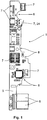
- the Figures 1 and 2 show the device 1 according to the invention for a motor-operated lock 2, which is shown in FIG Figure 3 is shown.
- Electronic components 7 are arranged on a carrier 5, which in the present case is designed as a two-sided printed circuit board.
- the carrier 5 is contoured so that it can be integrated into a lock housing 3 of the motor-operated lock 2.
- the carrier 5 has recesses 8 which leave out functional elements of the motor-operated lock 2, that is to say that the carrier 5 prevents mechanical restrictions on the functional elements of the motor-operated lock 2.
- the electronic components 7 are selected in terms of their arrangement and size such that they follow the contour of the carrier 5.
- an energy-storing element 6 is arranged on the carrier 5.
- This is a capacitor, more precisely two interconnected capacitors that are in direct proximity to one another, which can be designed as supercapacitors.
- the interconnected capacitors are placed on the carrier 5 in such a way that they can be integrated with the carrier 5 in the lock housing 3.
- the capacitors can also be arranged distributed over the carrier 5 and connected together.
- the capacitance of the interconnected capacitors is selected such that the motor-operated lock 2 can be moved into a predefined position via the device 1 according to the invention in the event of a power failure or power interruption.
- the energy in the energy-storing element 6 takes place essentially through electrostatic energy storage, the energy-storing element 6 having at least an energy density of 1J / cm 3 .
- the motor 13 is electrically connected to the energy-storing element 6.
- the motor 13 can be operated via a voltage source (not shown) or via the energy-storing element 6. In normal operation, the motor 13 is supplied with electrical energy via the voltage source.
- the stored energy of the energy-storing element 6 is used to rotate a drive wheel 14 connected to it via the operation of the motor 13 in order, as shown, to move the engagement element 20, which is arranged on the drive wheel 14, to be brought into an out of contact position with the slide 15.
- the energy-storing element 6 can be permanently charged by the voltage source.
- the switch 7, 24 is used to detect the position of the square drive.
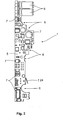
- Figure 3 shows schematically in a perspective view an interior view of a motor-operated lock 2 for a door with the one in FIG Figures 1 and 2 shown carrier 5 within the lock housing 3 for the motorized lock 2. Since the individual components of the motorized lock 3 are not relevant to the explanation of the invention, only essential elements of the motorized lock 2 are designated, which are intended for orientation. The functioning of the motor-operated lock 2 and the device 1 according to the invention are therefore not impaired in any way.
- the left side connection of the lock housing 3 is formed by a faceplate 9, which is penetrated by a lock latch 10, an additional latch head 11 and a bolt 12.
- a handle follower 19 is arranged in the motor-operated lock 2 or the lock housing 3 of the motor-operated lock 2 so that it can rotate about an actuation axis.
- An actuating arm 21 is attached to the handle follower 19.
- the actuating arm 21 can be fastened to the handle follower 19 in a force-locking manner.
- the actuating arm 21 is preferably designed in one piece, in particular monolithically, with the handle follower 19. When the handle follower 19 moves about the actuation axis, the actuation arm 21 comes into contact with the slide 15. This leads to a movement, in particular a displacement, of the slide 15.
- the slide 15 is operatively connected to a lock latch 10 and can move it from a locked position to an unlocked position in which the lock latch 10 and the additional latch head 11 are drawn in through the faceplate 9 in the direction of the lock housing 3.
- the slide 15 can be moved in a translatory manner, in particular can be moved linearly, in the motor-driven lock 2, in particular in the lock housing 3.
- a locking mechanism 22 is provided to transfer the movement of the slide 15 into a release of the lock latch 10.
- the motor-driven lock 2 also has a motor 13 with a motor-gear unit for driving the drive wheel 14, which is rotatably mounted about an axis of rotation.
- the motor 13 with the motor-gear unit also serves to unlock the lock latch 10, and in particular to move the slide 15.
- the power of the motor 13 is transmitted via a gear (not shown here) and a transmission element which is in operative contact with the drive wheel 14 is transferred to the slide 15.
- the transmission element can for example be designed as a drive worm.
- the drive wheel 14 which is preferably designed as a gear wheel, in particular as a worm wheel, can be rotated about its axis of rotation.
- the drive wheel 14 is eccentric to the axis of rotation of the drive wheel 14, an engagement element 20 is arranged.
- the engagement element 20 is designed such that when the drive wheel 14 rotates, the engagement element 20 moves the slide 15 via a slide contact surface 23 of the slide 15. In other words, when the slide 15 is displaced, the contact contour of the engagement element 20 slides along the slide contact surface 23.
- the engagement element 20 is in the present case designed as a cam. Due to the structural design of the engagement element 20, the motor only needs a relatively small motor torque in order to move the slide 15. If the engagement element 20 is rotated further, in particular rotated clockwise, the engagement element 20 comes into a contact position with the slide 15 via the contact contour 23 of the slide 15, whereby the translational movement of the slide 15 can be carried out.
- a lock cylinder 16 is located in the lock housing 3.
- the lock cylinder 16 is in operative connection with the slide 15 in such a way that the slide 15 is moved when the lock cylinder 16 is actuated by a key.
- the bolt 12 of the motor-operated lock 2 can be actuated, preferably retracted.
- an actuation axis 19 is arranged in the lock 2 for manual unlocking of the lock.
- An actuating member which is not explicitly shown, can be fastened in the actuating axis 19.
- the actuating member can be a rotary knob, a handle or the like, which can be actuated by a user to open the lock.
- a return spring 17, which acts on the handle follower 19, is arranged below the handle follower 19 or below the drive wheel 14.
- the actuation axis 19, the return spring 17 and the lock cylinder 16, which in the present case form functional elements 18 of the motor-operated lock 2 there is a device 1 according to the invention, the carrier 5 with the switching unit for controlling the device 1 and the energy-storing element 6 comprising, arranged within the lock housing 3.
- the contour of the carrier 5 is designed in such a way that it leaves out the drive wheel 14, the handle follower 19, the return spring 17 and the lock cylinder 16 of the motor-operated lock 2 at least in sections.
- functional elements 18 of lock housing 3, which in the present case serve to lead through locking elements are recessed from the contour of carrier 5.
- the carrier 5 can overlap at least in sections a printed circuit board 4 already built into the lock housing 3, on which, for example, electronics for querying the position of the lock 2 or its control technology is already installed.
- the carrier 5 is connected via this section to the printed circuit board 4 for data and / or voltage slide contact surface.
- the size of the interconnected capacitors is chosen so that they can be found in the lower right corner of the lock housing 3 below a functional element 18 of the lock housing 3.
Landscapes
- Business, Economics & Management (AREA)
- Emergency Management (AREA)
- Physics & Mathematics (AREA)
- Electromagnetism (AREA)
- Lock And Its Accessories (AREA)
Description
- Die vorliegende Erfindung betrifft ein motorbetriebenes Schloss und eine Vorrichtung für eine Tür zur elektrischen Versorgung des motorbetriebenen Schlosses gemäß dem Oberbegriff von Anspruch 1, wobei das Schloss ein Schlossgehäuse, eine zwischen einer Verriegeltposition und einer Entriegeltposition bewegbare Schlossfalle, einen translatorisch beweglich gelagerten Schieber sowie einen Sperrmechanismus aufweist (umfasst), auf den der Schieber wirkt und dabei die Schlossfalle freigibt. Ferner weist das Schloss eine Motor- Getriebe- Einheit zum Bewegen des Schiebers über eine Engriffseinrichtung auf.
- Derartige Türschlösser sind vielfach bekannt. D. h., es existiert eine Vielzahl von Schieber gesteuerten Türschlössern am Markt. Bei diesen Türschlössern erfolgt die "Steuerung" der Abläufe im Türschloss über einen Schieber. Bei derartigen Türschlössern wird der beweglich gelagerte Schieber über eine Motor-Getriebe-Einheit bewegt. D. h., die Motor-Getriebe-Einheit ist für das Entriegeln des Türschlosses zuständig, indem sie den Schieber anhebt. Beispiele für Schließvorrichtungen mit motorischer Antriebseinrichtung zur Betätigung der Riegel eines Schlosses finden sich in
EP 2 016 243 B1 undEP 1 203 860 A1 . - Die bekannten Türschlösser weisen einen translatorisch beweglich gelagerten Schieber auf. Der Schieber ist vorteilhafterweise in dem Schlossgehäuse des Türschlosses beweglich gelagert. Der Schieber steht mit einer Schlossfalle des Türschlosses in Wirkverbindung. Die Schlossfalle des Türschlosses ist zwischen einer Verriegeltposition und einer Entriegeltposition bewegbar. In der Verriegeltposition ragt die Schlossfalle, die insbesondere als Kreuzfalle ausgebildet sein kann, aus dem Türschloss, insbesondere dem Schlossgehäuse, heraus, um so in Eingriff in eine Schlossfallenaufnahme eines Türrahmens zu gelangen. In der Entriegeltposition ist die Schlossfalle zur Freigabe der Tür in das Türschloss bzw. das Schlossgehäuse hineingezogen. Die Schlossfalle kann zwischen beiden Position verschwenkt werden. Bevorzugt ist die Schlossfalle zwischen der Verriegeltposition und der Entriegeltposition linear bewegbar gelagert.
- Die Wirkverbindung zwischen dem Schieber und der Schlossfalle wird durch den Sperrmechanismus, auch als Gelenkmechanismus bezeichnet, des Türschlosses hergestellt. Der Sperrmechanismus verriegelt dabei die Schlossfalle. Durch eine translatorische Bewegung des Schiebers wird die Verriegelung des Sperrmechanismus aufgehoben. Nur durch ein Aufdrücken der Tür wird dabei die Schlossfalle bewegt. Wie auch die Schlossfalle wird auch der Zusatzfallenkopf nur durch Aufdrücken der Tür bewegt. Dabei kommt es aber bei dem Zusatzfallenkopf zu keinem Zeitpunkt zu einer Verriegelung des Schlosses.
- Der Schieber wird bei den bekannten motorbetriebenen Türschlössern von einer Eingriffseinrichtung mitgenommen, beispielsweise von einem Dorn, der sich auf einem Schneckenrad der Motor-Getriebe-Einheit befindet, und der bei einer Drehung des Schneckenrades auf den Schieber auftrifft, wodurch der Schieber innerhalb des Türschlosses bzw. des Schlossgehäuses bewegt, insbesondere linear verschoben wird.
- Als Eingriffseinrichtung ist auch ein an einem Antriebsrad angeordnetes Eingriffselement bekannt, wobei das Antriebsrad durch die Motor-Getriebe-Einheit angetrieben wird. In vorteilhafter Weise ist dabei die Eingriffseinrichtung exzentrisch zur Drehachse des Antriebsrades angeordnet und ist derart ausgebildet, dass bei einer Drehbewegung des Antriebsrades das Eingriffselement die Verschiebung des Schiebers über eine Schieberkontaktfläche, d. h. durch Kontaktierung der Schieberkontaktfläche, durchführt. Bei der Verschiebung des Schiebers gleitet dabei die Anlagekontur des Eingriffselements an der Schieberkontaktfläche entlang.
- D. h., durch die exzentrische Anordnung des Eingriffselements an dem Antriebsrad gelangt das Eingriffselement bei einer Drehung des Antriebsrades in Kontakt mit dem Schieber und nimmt diesen bei der Drehung mit. Der Schieber wird dadurch innerhalb des Türschlosses bzw. des Schlossgehäuses bewegt, insbesondere linear verschoben. Wird das Antriebsrad mit dem darauf angeordneten Eingriffselement bevorzugt weiter im Uhrzeigersinn gedreht, gelangt das Eingriffselement außer Kontakt mit dem Schieber, d. h. in eine Außerkontaktstellung mit dem Schieber. In der Außerkontaktstellung kann die Schlossfalle auf den Sperrmechanismus wirken, was zu einer Bewegung des Schiebers führt, wodurch wiederum der Riegel in seine Verriegelungsposition verfahrbar ist. Diese Wirkverbindung zwischen der Außerkontaktstellung des Eingriffselements bzw. der Eingriffseinrichtung mit dem Schieber, der Schlossfalle und dem Riegel wird insbesondere als notwendige Maßnahme für eine Brandschutztür angesehen.
- Kommt es aber zu einer Stromunterbrechung bzw. zu einem Stromausfall, d. h. dass die Motor-Getriebe-Einheit, insbesondere der Motor, der zum Antreiben des um die Drehachse drehbar gelagerten Antriebsrades mit dem darauf angeordneten Eingriffselements oder die zur Mitnahme des Dorns dient, der beispielsweise auf einem Schneckenrad der Motor-Getriebe-Einheit angeordnet ist, nicht mehr energetisch versorgt wird, kann dies in einer bestimmten Stellung des Eingriffselements oder des Dorns relativ zum Schieber, nämlich dann, wenn sich das Eingriffselement oder der Dorn mit dem Schieber in einer Kontaktstellung befindet, zu einer Blockierung des Schiebers, d. h. zu einer Hemmung der translatorischen Bewegung des Schiebers kommen. Dadurch kann die zur Betätigung des Sperrmechanismus bestimmte Kraft nicht von bzw. auf den Schieber übertragen werden, sodass eine Verriegelung, beispielsweise einer Panik- oder Brandschutztür, nicht mehr gewährleistet ist, insbesondere der mit dem Schieber gekoppelte Riegel nicht in seine Verriegelungsposition bewegbar ist. Auch darf eine Kontaktstellung des Eingriffselements oder des Dorns mit dem Schieber nicht dazu führen, dass eine verriegelte Panik- oder Brandschutztür nicht mehr den Panik- oder Fluchtweg freigibt.
- Als Eingriffsvorrichtung soll vorliegend das Eingriffselement und der Dorn verstanden werden.
- Es ist daher die Aufgabe der vorliegenden Erfindung, eine Vorrichtung zur elektrischen Versorgung für ein motorbetriebenes Schloss zu schaffen, welches im Falle einer Stromunterbrechung bzw. im Falle eines Stromausfalls der Motor-Getriebe-Einheit, insbesondere dem Motor noch so viel Energie zur Verfügung stellt, dass die Eingriffseinrichtung oder der Dorn, die in Kontaktstellung mit dem Schieber stehen, außer Kontakt mit dem Schieber gebracht werden können. Zudem ist es die Aufgabe der vorliegenden Erfindung, den Montageaufwand und die Herstellungskosten für eine Vorrichtung zur elektrischen Versorgung für ein motorbetriebenes Schloss zu reduzieren, wobei die Vorrichtung einfach und platzsparend aufgebaut sein soll.
- Diese Aufgabe wird ausgehend von einem motorbetriebenen Schloss und einer Vorrichtung zur elektrischen Versorgung für das motorbetriebenes Schloss gemäß dem Oberbegriff des Anspruchs 1 in Verbindung mit dessen kennzeichnenden Merkmalen gelöst. Vorteilhafte Weiterbildungen sind in den abhängigen Ansprüchen angegeben.
- Die Erfindung schließt die technische Lehre ein, dass in das Schlossgehäuse ein Energie speicherndes Element integrierbar ist, und dass das Energie speichernde Element an eine Spannungsquelle anschließbar ist, und wobei das Energie speichernde Element wenigstens so ausgelegt ist, dass im Falle eines Stromausfalls oder einer Stromunterbrechung der Motor elektrisch betreibbar ist, um die Eingriffseinrichtung aus einer Kontaktstellung mit dem Schieber zu bewegen.
Die erfindungsgemäße Vorrichtung soll daher auch als Gangreserve verstanden werden. Die Energie im Energie speichernden Element erfolgt im Wesentlichen durch eine elektrostatische Energiespeicherung, wobei der Energiespeicher mindestens eine Energiedichte von 1J/cm3 aufweist. Dabei ist 1J=1Ws. So kann die Leistung des Motors der Motor-Getriebe-Einheit z. B. 1 Watt betragen. Bei einer Energiedichte von 1J/cm3 und einer angenommenen Größe des Energiespeichers von 1 cm3 könnte die elektrische Komponente im Idealfall 1 s betrieben werden. Die Anordnung der erfindungsgemäßen Vorrichtung kann daher in dem Schlossgehäuse erfolgen. Die Anordnung der erfindungsgemäßen Vorrichtung mit dem Energiespeicher kann dementsprechend ohne Schaffung eines zusätzlichen Bauraumes in der Tür erfolgen. - Ein Elektrolytkondensator, der ebenfalls im Wesentlichen durch eine elektrostatische Energiespeicherung die Energie speichert, weist z. B. bei einem Volumen von 22 cm3 eine Energiedichte von 0,125 J/cm3 auf. Dies bedeutet, dass zum Betrieb des Motors der Motor-Getriebe-Einheit über 1 s mit einer Leistung von 1 W durch einen Elektrolytkondensator das Volumen des Elektrolytkondensators 176 cm3 betragen muss. Dies entspricht einer Seitenlänge des Elektrolytkondensators von ca. 5,6 cm in der Annahme, dass der Elektrolytkondensator würfelförmig ausgestaltet ist.
- In einer bevorzugten Weiterbildung ist es vorgesehen, dass das Energie speichernde Element bevorzugt eine Energiedichte von mindestens 5J/cm3 aufweist, besonders bevorzugt eine Energiedichte von mindestens 8 J/cm3 aufweist. Je größer die Energiedichte, desto länger ist eine Betriebsdauer des Motors der Motor-Getriebe-Einheit mit einer bestimmten Leistung. So kann die Leistung des Motors der Motor-Getriebe-Einheit z. B. 5 Watt betragen. Bei einer Energiedichte von 5J/cm3 und einer angenommenen Größe des Energie speichernden Elements von 1 cm3 könnte der Motor der Motor-Getriebe-Einheit im Idealfall 1 s betrieben werden. Je höher die Energiedichte des Energie speichernden Elements ist, desto länger kann auch der Betrieb des Motors der Motor-Getriebe-Einheit durch das Energie speichernden Element erfolgen. Dementsprechend kann mit einem Energie speichernden Element von 8J/cm3 der Motor der Motor-Getriebe-Einheit mit einer Leistung von 1 Watt 8s betrieben werden. Dadurch kann wirkungsvoll die Eingriffseinrichtung in Außerkontaktstellung mit der Anlagenkontur des Schiebers gebracht werden.
- Weiterhin ist es vorteilhaft, dass der Energiespeicher ein Superkondensator ist. Ein Superkondensator kann dabei ein Doppelschichtkondensator, ein Pseudokondensator oder ein Hybridkondensator sein. Auch ist eine Kombination aus Doppelschichtkondensator, Pseudokondensator und Hybridkondensator denkbar. Der Superkondensator, insbesondere der Doppelschicht-kondensator zeichnet sich dadurch aus, dass die Energiedichte bei gleichem Volumen verglichen mit einem Elektrolytkondensator bis zu 60 Mal größer ist. Zudem unterliegt ein Superkondensator gegenüber einem Akkumulator nahezu keiner kalendarischen Alterung. Auch hängen die Verfügbarkeit und der Betrieb eines Superkondensators nahezu nicht von den Lade- und Entladezyklen ab. Der Einsatz eines Superkondensators anstatt eines z. B. herkömmlichen Elektrolytkondensators ermöglicht somit eine platzsparende Bauweise der gesamten Vorrichtung, wobei sich die Vorrichtung in dem Schlossgehäuse des motorbetriebenen Schlosses derart anordnen lässt, wodurch die räumlich-körperliche Ausdehnung der Tür, insbesondere einer Fluchttür für Menschen nicht von der räumlich-körperlichen Ausdehnung der Vorrichtung tangiert ist.
- Besonders vorteilhaft ist es, dass ein Abwärtswandler die elektrische Spannung in eine niedrigere Spannung umwandelt, wobei durch die niedrigere Spannung der Energiespeicher ladbar ist. Eine Nennspannung des Energiespeichers kann weit unterhalb der abgreifbaren elektrischen Spannung der Energie der Spannungsquelle liegen, sodass der Abwärtswandler die elektrische Spannung auf die Nennspannung umwandeln kann. In der Industrie wird häufig z. B. eine Gleichspannung von 24 Volt eingesetzt. Die Nennspannung eines Superkondensators als Doppelschichtkondensator kann dabei 2,5 Volt betragen. Um einer Zerstörung des Superkondensators entgegenzuwirken, kann über den Abwärtswandler die höhere abgreifbare Spannung auf die niedrigere Nennspannung umgewandelt werden.
- Zudem ist es vorteilhaft, dass an dem Energiespeicher eine Konstantstromquelle elektrisch angeordnet ist. Die Konstantstromquelle kann zur Begrenzung eines Ladestroms während der Ladung des Energiespeichers genutzt werden. Zudem kann eine Überlastung des Abwärtswandlers durch die Konstantstromquelle vermieden werden. Außerdem wird ein korrekter Betrieb zur Ladung des Energiespeichers gewährleistet.
- Ferner ist es denkbar, dass wenigstens zwei Energiespeicher in Reihe geschaltet sind. Durch Schaltung von Energiespeichern in Reihe kann die Spannung durch die in Reihe geschalteten Energiespeicher erhöht werden. Im Falle, dass z. B. ein Energiespeicher 2,5 Volt Nennspannung aufweist, sind in der Reihenschaltung von zwei Energiespeichern mit einer Nennspannung von 2,5 Volt 5 Volt durch die Reihenspannung der zwei Energiespeicher erreichbar. Auch ist es denkbar, dass eine Parallelschaltung von Energiespeichern erfolgen kann, wodurch sich die Kapazität durch die zwei in Parallelschaltung geschalteten Energiespeicher erhöht. Weiterhin kann eine Kombination aus einer Parallel- und Reihenschaltung von Energiespeichern erfolgen. Durch die Erhöhung der Spannung durch die in Reihe geschalteten Energiespeicher kann dementsprechend die elektrische Leistung durch die in Reihe geschalteten Energiespeicher erhöht werden. Dies gilt ebenfalls für eine Parallelschaltung, wobei sich die elektrische Leistung aus dem Produkt von Spannung mal Strom bestimmt.
- Ferner ist es denkbar, dass durch einen Aufwärtsregler eine Erhöhung der niedrigeren Spannung durch den Aufwärtsregler auf eine erste Ausgangsspannung erfolgt. Durch den Aufwärtsregler kann eine Verdoppelung der niedrigen Spannung erfolgen. Dabei bietet der Aufwärtsregler einen guten Wirkungsgrad mit einer einfachen Induktivität. Zudem können höhere Spannungen mit einem guten Wirkungsgrad mittels eines Übertragers erfolgen. Der Übertrager kann dabei ein Transformator sein.
- Ebenfalls ist es erfindungsgemäß denkbar, dass eine Erhöhung der ersten Ausgangsspannung durch eine Kaskadeneinheit auf eine zweite Ausgangsspannung erfolgt. Dabei kann die Kaskadeneinheit eine Villardkaskade sein. Der Platzbedarf einer Villardkaskade ist dabei gegenüber einem Übertrager, insbesondere einem Transformator gering, da lediglich Dioden und Kondensatoren für den Aufbau der Villardkaskade zum Einsatz kommen. Dabei kann eine Eingangsspannung der Villardkaskade in eine nahezu beliebig hohe Ausgangsspannung umgewandelt werden. Je nach Anzahl von Dioden und Kondensatoren, die in der Villardkaskade zum Einsatz kommen, kann eine beliebig hohe zweite Ausgangsspannung erzeugt werden. Die Villardkaskade wandelt eine zugeführte Wechselspannung in eine hohe Gleichspannung um, wobei die Höhe der Gleichspannung sich nach der Anzahl der genutzten Dioden und Kondensatoren innerhalb der Schaltung der Villardkaskade bestimmt.
- In einer bevorzugten Weiterbildung ist es vorgesehen, dass die Ladung der in Reihe geschalteten Energiespeicher durch eine passive Symmetrierschaltung erfolgt. Dabei kann die Symmetrierschaltung mit Widerständen aufgebaut sein. So können bei einem Einsatz von zwei Energiespeichern zwei Widerstände in Reihe geschaltet sein und durch die Reihenschaltung mit der passiven Symmetrierung die Ladung der Energiespeicher permanent erfolgen. Vorteilhafterweise kann bei einem Spannungsausfall die elektrische Versorgung aus den Energiespeichern direkt erfolgen. Eine Symmetrierschaltung mit zwei Energiespeichern kann dementsprechend zwei in Reihe geschaltete Widerstände aufweisen, wobei an jedem Widerstand ein Energiespeicher parallel geschaltet ist. Im Falle, dass die Energiespeicher die gleiche Nennspannung aufweisen, ist es vorteilhaft, dass die Widerstände gleiche Widerstandswerte aufweisen.
- Vorteilhaft ist es ebenfalls, dass eine Schalteinheit an dem Energiespeicher angeordnet ist, wobei durch die Schalteinheit elektrische Energie des Energiespeichers an den Motor der Motor-Getriebe-Einheit übertragbar ist. Die Schalteinheit kann dabei ein Transistor sein, wobei eine Basis des Transistors an die abgreifbare elektrische Spannung der Spannungsquelle elektrisch angeordnet sein kann. Bei einem Ausfall der elektrischen Spannung ändert der Transistor seinen Schaltzustand, wodurch die elektrische Energie des Energiespeichers an den Motor der Motor-Getriebe-Einheit übertragbar ist. Die Schalteinheit kann auch ein Relais sein, wobei das Relais mit einem Eingang an die abgreifbare elektrische Spannung elektrisch angeordnet sein kann. Bei einem Ausfall der elektrischen Spannung kann sich ebenfalls ein Schaltzustand des Relais ändern. Der Schaltzustand der Schalteinheit kann dabei ein Schließen oder ein Öffnen eines Schalters sein.
- In vorteilhafter Weise sind die Schalteinheit und das Energie speichernde Element der erfindungsgemäßen Vorrichtung auf einem Träger innerhalb des Schlossgehäuses und insbesondere an eventuell bereits vorhandene Schaltkreise, für beispielsweise Positionssensoren, die auf einer Leiterplatte des motorbetriebenen Schlosses angeordnet sind, und dessen eventuell bereits vorhandene Energieversorgung anschließbar. Das bedeutet in vorteilhafter Weise, dass die Energieversorgung des Energie speichernden Elements der Vorrichtung als auch deren Schalteinheit für das motorbetriebene Schloss innerhalb des Schlossgehäuses erfolgt, weshalb ein separater Kabelübergang aus dem Schlossgehäuse heraus zu einer außerhalb des Schlossgehäuses angeordneten Energie- bzw. Spanungsquelle überflüssig wird.
- Um das Energie speichernde Element und die für die Schalteinheit notwendigen Bauteile der Vorrichtung innerhalb des Schlossgehäuses anordnen zu können, sind diese zur Einschränkung der Baugröße erfindungsgemäß auf eine bestimmte Kapazität und Funktion reduziert, nämlich bei Stromausfall oder bei Stromunterbrechung, das motorbetriebene Schloss zumindest einmalig in eine vordefinierte Position zu verfahren. Bevorzugt ist als vordefinierte Position dabei das Außerkontaktbringen des Schiebers mit der Eingriffseinrichtung zu verstehen.
- Durch die funktionelle Einschränkung der erfindungsgemäßen Vorrichtung und deren dadurch bedingte Minimierung der Baugröße kann eine vollfunktionsfähige Vorrichtung zur Verfügung gestellt werden, die sich in dem Schlossgehäuse für das motorbetriebene Schloss integrieren lässt, wodurch sich der Montageaufwand und damit die Kosten für die Montage der Vorrichtung drastisch reduzieren lassen.
- Vorzugsweise ist der Träger eine ein- oder zweiseitige Leiterplatte, die auch mehrlagig ausgebildet sein kann, Leiterkarte, Platine oder gedruckte Schaltung für elektronische Bauteile. Vorliegend kann als Träger auch die Leiterplatte mit der darauf angeordneten Schalteinheit zur Steuerung des motorbetriebenen Schlosses verstanden werden. In diesem Fall sind der Träger und die Leiterplatte integral miteinander ausgebildet. Das bedeutet, dass die Schalteinheit und das Energie speichernde Element der Gangreserve vorzugsweise direkt auf der Leiterplatte zur Steuerung des motorbetriebenen Schlosses angeordnet sind. Eine zusätzliche Verdrahtung oder ein Kabelübergang zwischen der Leiterplatte und dem Träger werden damit überflüssig.
- Um jedoch auch schon bereits hergestellte oder bereits installierte motorbetriebene Schlösser nachrüsten zu können, ist der Träger vorzugsweise eine weitere Leiterplatte, Leiterkarte, Platine oder gedruckte Schaltung, der oder die an die Leiterplatte und/oder die Energieversorgung des motorbetriebenen Schlosses anschließbar ist. Besonders bevorzugt erfolgt ein Anschließen des Trägers an die Leiterplatte durch ein Aufstecken oder ein Anstecken des Trägers auf oder an die Leiterplatte. Dies kann beispielsweise über Steckverbindungen erfolgen, die sowohl einen mechanischen als auch einen daten- und energieverbindenden Kontakt zwischen der Leiterplatte und dem Träger herstellen. Natürlich ist es auch denkbar, die Leiterplatte und den Träger innerhalb des Gehäuses über einen Kabelübergang zu verbinden.
- Weist das motorbetriebene Schloss darüber hinaus auch Sensoren auf, die die Möglichkeit bieten, die Schlossfunktionen sensorisch zu erfassen, sollte in besonders bevorzugter Weise die Kapazität der des Energie speichernden Elements der erfindungsgemäßen Vorrichtung derart ausgelegt sein, dass zumindest ein Signal an eine Steuereinheit oder Überwachung weitergeleitet werden kann. Dies ist insbesondere zur Überwachung von motorbetriebenen Schlössern notwendig, wenn diese beispielsweise in Großobjekten in sicherheitssensiblen Bereichen eingesetzt werden.
- Natürlich kann als Energie speicherndes Element auch ein Akkumulator oder zwei oder mehr zusammen geschaltete Akkumulatoren eingesetzt werden. Es ist auch denkbar, andere Energie- bzw. Stromquellen als die genannten Energie speichernden Elemente in der erfindungsgemäßen Vorrichtung zu verbauen. Allerdings müssen insgesamt die Energie speichernden Elemente die Voraussetzung erfüllen, dass diese in dem Schlossgehäuse einsetzbar sind und zudem eine ausreichende elektrische Kapazität bieten, die es ermöglicht, das motorbetriebene Schloss in eine wie oben beschriebene vordefinierte Position zu fahren. Selbstverständlich ist auch eine Kombination unterschiedlicher Energie speichernder Elemente denkbar. So könnte beispielsweise ein Kondensator in Kombination mit einem Akkumulator in der erfindungsgemäßen Gangreserve verbaut sein.
- Egal, ob die Vorrichtung und das Energie speichernde Element integral mit der Leiterplatte ausgebildet sind oder ob die Vorrichtung und das Energie speichernde Element modular, d. h. als ein mit der Leiterplatte zu verbindendes Bauteil ausgestaltet sind, sollte der Träger, die Schalteinheit, die elektronischen Bauteile und das Energie speichernde Element umfassend, so ausgestaltet bzw. so im Schlossgehäuse angeordnet sein, dass es zu keiner Funktionsbeeinträchtigung des motorbetriebenen Schlosses kommt. Dazu ist vorzugsweise der Träger der Vorrichtung derart konturiert, dass er Funktionselemente des motorbetriebenen Schlosses ausspart. Das bedeutet, dass der beispielsweise als Leiterplatte oder Platine ausgestaltete Träger in seiner Form den funktionellen Elementen und deren Lage im Schlossgehäuse angepasst ist, um einen mechanischen Kontakt mit diesen Elementen zu vermeiden, was im äußersten Fall zu einem Funktionsverlust des Schlosses führen würde.
- Ein Verfahren, das durch das erfindungsgemäße Kombination des motorbetriebenen Schlosses und die Vorrichtung zur elektrischen Versorgung des Schlosses durchführbar sein kann, beinhaltet, dass das motorbetriebene Schloss durch eine Spannungsquelle zum Öffnen und zum Verschließen der Tür elektrisch betrieben wird und ein Energie speicherndes Element durch eine an der Spannungsquelle abgreifbare elektrische Spannung geladen wird, wobei bei einem Ausfall der elektrischen Spannung das motorbetriebene Schloss durch das Energie speichernde Element elektrisch betrieben wird. Erfindungsgemäß ist dabei vorgesehen, dass die Energie im Energie speichernden Element im Wesentlichen durch eine elektrostatische Energiespeicherung erfolgt, wobei das Energie speichernde Element mindestens eine Energiedichte von 1J/cm3 aufweist.
- Besonders vorteilhaft ist es, dass an dem Energie speichernden Element eine Schalteinheit angeordnet ist und dass bei einem Ausfall der elektrischen Spannung durch eine Änderung eines Schaltzustandes der Schalteinheit eine Energieabgabe der in dem Energie speichernden Element geladenen Energie an den Motor der Motor-Getriebe-Einheit bewirkt wird. Die Schalteinheit kann dabei ein Transistor oder ein Relais sein. Ein Schaltzustand kann dabei eine geöffnete Schalterstellung oder eine geschlossene Schalterstellung sein. Durch den Einsatz eines Transistors als Schalteinheit kann eine schnelle und gesicherte Abgabe der Energie durch das Energie speichernde Element an den Motor der Motor-Getriebe-Einheit durch eine schnelle Umschaltung von einem ersten Schaltzustand zu einem zweiten Schaltzustand erfolgen. Zudem ist die Wahl eines Transistors, der auch ein Feldeffekttransistor sein kann, von Vorteil, da dieser in der SMD-Technik auf einer Platine angeordnet sein kann. Die Wahl eines Transistors oder eines Feldeffekttransistors in der SMD-Technik bietet den Vorteil, dass ein Aufbau der erfindungsgemäßen Vorrichtung in einer bauraumoptimierten Weise erfolgen kann.
- Weiterhin ist es vorteilhaft, dass die abgreifbare Spannung der Spannungsquelle durch einen Abwärtsregler auf eine niedrigere Spannung als die abgreifbare Spannung reduziert wird, wobei durch die niedrigere Spannung der Energiespeicher geladen wird. Die Nutzung eines Abwärtswandlers bietet den Vorteil, dass bei einer hohen abgreifbaren Spannung auch Energie speichernde Elemente mit einer sehr niedrigen Nennspannung eingesetzt werden können. Da das Energie speichernde Element beispielsweise ein Superkondensator sein kann, beträgt z. B. für einen Doppelschichtkondensator eine Nennspannung ca. 2,5 Volt. Bei einer abgreifbaren Spannung von 24 Volt oder 30 Volt kann durch den Abwärtswandler die abgreifbare Spannung auf die Nennspannung von 2,5 Volt reduziert werden. Dabei können Energie speichernde Elemente in Reihe angeordnet werden, wobei z. B. zwei Energie speichernde Elemente mit einer Nennspannung von 2,5 Volt eine Spannung von 5 Volt benötigen. Die benötigten 5 Volt können über den Abwärtswandler zur Verfügung gestellt werden, wobei die Energie speichernden Elemente, die in Reihe geschaltet sind, über eine Symmetrieschaltung, insbesondere durch eine Verwendung von Widerständen geladen werden können. Bei der Nutzung von zwei Energie speichernden Elementen mit der gleichen Nennspannung bietet sich daher die Ausbildung von zwei Widerständen in Reihe mit gleichen Widerstandswerten an. Die in Reihe geschalteten Widerstände mit den gleichen Widerstandswerten bilden einen Spannungsteiler, wobei über jeden Widerstand die gleiche Spannung abfällt. Bei einem Anlegen von 5 Volt an die in Reihe geschalteten Widerstände fällt dementsprechend eine Spannung von 2,5 Volt pro Widerstand ab. An diesen Widerständen können dann parallel jeweils ein Energiespeicher mit einer Nennspannung von 2,5 Volt angeordnet werden.
- Erfindungsgemäß kann es vorgesehen sein, dass die niedrige Spannung auf eine höhere Spannung, insbesondere im Wesentlichen auf den Betrag der Eingangsspannung der Spannungsquelle vergrößert wird. Die Vergrößerung der niedrigen Spannung auf den Betrag der Eingangsspannung bietet den Vorteil, dass ein Austausch eines bereits verbauten motorbetriebenen Schlosses in einer Tür, welches direkt durch eine Spannungsquelle energetisch versorgt wird, bei einem nachträglichen Einbau der erfindungsgemäßen Vorrichtung, nicht zu erfolgen braucht. Dies senkt nachhaltig die Kosten für den nachträglichen Einbau der erfindungsgemäßen Vorrichtung für eine Tür, die bereits mit einem motorbetriebenen Schloss ausgerüstet ist. Die erfindungsgemäße Vorrichtung und auch das Verfahren bieten den Vorteil, dass bereits verbaute motorbetriebene Schlösser für eine Tür mit einer bestimmten Voltzahl und einer dazu bestimmten abgreifbaren Spannung einer Energiequelle weiterhin genutzt werden können, da lediglich zwischen der Energiequelle mit der abgreifbaren Spannung und des motorbetriebenen Schlosses die erfindungsgemäße Vorrichtung oder das erfindungsgemäße Verfahren angewendet werden kann. Zudem bietet der Einsatz eines Superkondensators als Energiespeicher den Vorteil, dass die gesamte Vorrichtung erfindungsgemäß in dem bauraumbegrenzten Schlossgehäuse angeordnet werden kann.
Die Vorrichtung kann bei Nutzung von zwei Superkondensatoren als Doppelschichtkondensatoren mit einer Nennspannung von 2,5 Volt auf einer Platine mit den Ausmaßen von 1,7 cm x 8,5 cm angeordnet sein. Bei einer Bauhöhe von ca. 1 cm und einer Konturierung, die die mechanischen Bauteile des Schlosses ausspart, kann damit die gesamte Vorrichtung als eine Baueinheit in dem Schlossgehäuse angeordnet werden und an die eventuell bereits vorhandene Leiterplatte und/oder die Spannungsquelle des motorbetriebenen Schlosses angeschlossen werden. - Weitere, die Erfindung verbessernde Maßnahmen werden nachstehend mit der Beschreibung eines bevorzugten Ausführungsbeispiels der Erfindung anhand der Figuren näher dargestellt. Es zeigt:
- Fig. 1
- eine Draufsicht auf die Vorderseite eines Trägers der Vorrichtung in Form einer Leiterplatte, auf dem die Schalteinheit und das Energie speichernde Element der Vorrichtung angeordnet sind,
- Fig. 2
- eine Draufsicht auf die Rückseite des Trägers aus
Figur 1 und - Fig. 3
- in einer perspektivischen Ansicht eine Innenansicht eines motorbetriebenen Schlosses für eine Tür mit dem Träger der Vorrichtung aus den
Figuren 1 und2 in einem Schlossgehäuse. - In den unterschiedlichen Figuren sind gleiche Teile stets mit denselben Bezugszeichen versehen, weshalb diese in der Regel auch nur einmal beschrieben werden.
- Die
Figuren 1 und2 zeigen die erfindungsgemäße Vorrichtung 1 für ein motorbetriebenes Schloss 2, welches inFigur 3 dargestellt ist.
Auf einem Träger 5, der vorliegend als zweiseitige Leiterplatte ausgestaltet ist, sind elektronische Bauteile 7 angeordnet. Die elektronischen Bauteile 7 bilden zusammen mit Leiterbahnen auf dem Träger 5 die Schalteinheit zur Steuerung der Vorrichtung 1. Der Träger 5 ist so konturiert, dass dieser in ein Schlossgehäuse 3 des motorbetriebenen Schlosses 2 integrierbar ist. Dazu weist der Träger 5 Aussparungen 8 auf, die Funktionselemente des motorbetriebenen Schlosses 2 aussparen, d. h., dass mechanische Einschränkungen der Funktionselemente des motorbetriebenen Schlosses 2 durch den Träger 5 verhindert werden. Um das zu erreichen, sind die elektronischen Bauteile 7 in ihrer Anordnung und Größe so gewählt, dass sie der Kontur des Trägers 5 folgen. - Zusätzlich zu den elektronischen Bauteilen 7, ist auf dem Träger 5 ein Energie speicherndes Element 6 angeordnet. Dabei handelt es sich um einen Kondensator, genauer gesagt um zwei zusammengeschaltete Kondensatoren, die in direkter Nachbarschaft zueinander liegen, die als Superkondensatoren ausgebildet sein können. Die zusammengeschalteten Kondensatoren sind so auf dem Träger 5 platziert, dass diese mit dem Träger 5 in das Schlossgehäuse 3 integrierbar sind. Natürlich können die Kondensatoren auch über den Träger 5 verteilt angeordnet und zusammengeschaltet sein.
- Die Kapazität der zusammengeschalteten Kondensatoren ist so gewählt, dass über die erfindungsgemäße Vorrichtung 1 bei einem Stromausfall oder einer Stromunterbrechung das motorbetriebene Schloss 2 in eine vordefinierte Position verfahrbar ist. Die Energie im Energie speichernden Element 6 erfolgt im Wesentlichen durch eine elektrostatische Energiespeicherung, wobei das Energie speichernde Element 6 mindestens eine Energiedichte von 1J/cm3 aufweist. An dem Energie speichernden Element 6 ist der Motor 13 elektrisch verbunden. Der Motor 13 kann über eine Spannungsquelle (nicht dargestellt) oder über das Energie speichernde Element 6 betrieben werden. In einem Normalbetrieb wird der Motor 13 über die Spannungsquelle mit elektrischer Energie versorgt. Im Falle eines Ausfalles der Spannungsquelle wird die gespeicherte Energie des Energie speichernden Elements 6 dazu genutzt, um über den Betrieb des Motors 13 ein damit verbundenes Antriebsrad 14 zu drehen, um, wie dargestellt, das Eingriffselement 20, welches auf dem Antriebsrad 14 angeordnet ist, in eine Außerkontaktstellung mit dem Schieber 15 zu bringen. Im Normalbetrieb kann das Energie speichernde Element 6 durch die Spannungsquelle permanent geladen werden.
- Ein Schalter 7, 24, bei dem es sich auch um ein elektronisches Bauteil 7 handelt, welches auf dem Träger 5 angeordnet ist, liegt an einem Vierkantantrieb für eine Drückernuss 19, wie in
Figur 3 dargestellt, an. Dabei dient der Schalter 7, 24 der Erfassung der Stellung des Vierkantantriebes. -
Figur 3 zeigt schematisch in einer perspektivischen Ansicht eine Innenansicht eines motorbetriebenen Schlosses 2 für eine Tür mit dem in denFiguren 1 und2 dargestellten Träger 5 innerhalb des Schlossgehäuses 3 für das motorbetriebene Schloss 2. Da zur Erläuterung der Erfindung die einzelnen Bauteile des motorbetriebenen Schlosses 3 nicht relevant sind, werden nur wesentliche Elemente des motorbetriebenen Schlosses 2 bezeichnet, die zur Orientierung dienen sollen. Es wird somit die Funktionsweise des motorbetriebenen Schlosses 2 und der erfindungsgemäßen Vorrichtung 1 in keiner Weise beeinträchtigt. - Den linken seitlichen Anschluss des Schlossgehäuses 3 bildet ein Stulp 9, der von einer Schlossfalle 10, einem Zusatzfallenkopf 11 und einem Riegel 12 durchbrochen wird.
- Eine Drückernuss 19 ist um eine Betätigungsachse drehbar in dem motorbetriebenen Schloss 2 bzw. dem Schlossgehäuse 3 des motorbetriebenen Schlosses 2 angeordnet. An der Drückernuss 19 ist ein Betätigungsarm 21 befestigt. Der Betätigungsarm 21 kann kraftschlüssig an der Drückernuss 19 befestigt sein. Bevorzugt ist der Betätigungsarm 21 einstückig, insbesondere monolithisch, mit der Drückernuss 19 ausgebildet. Bei einer Bewegung der Drückernuss 19 um die Betätigungsachse gelangt der Betätigungsarm 21 in Kontakt mit dem Schieber 15. Dies führt zu einer Bewegung, insbesondere einer Verschiebung, des Schiebers 15.
- Der Schieber 15 ist mit einer Schlossfalle 10 wirkverbunden und kann diese durch seine Bewegung von einer Verriegeltposition in eine Entriegeltposition überführen, in der die Schlossfalle 10 und der Zusatzfallenkopf 11 durch den Stulp 9 in Richtung des Schlossgehäuses 3 eingezogen wird. Der Schieber 15 ist translatorisch bewegbar, insbesondere linear bewegbar, in dem motorbetriebenen Schloss 2, insbesondere in dem Schlossgehäuse 3, gelagert. Zur Übertragung der Bewegung des Schiebers 15 in eine Freigabe der Schlossfalle 10 ist ein Sperrmechanismus 22 vorgesehen.
- Das motorbetriebene Schloss 2 weist ferner einen Motor 13 mit einer Motor-Getriebe-Einheit zum Antreiben des um eine Drehachse drehbar gelagerten Antriebsrades 14 auf. Der Motor 13 mit der Motor-Getriebe-Einheit dient ebenfalls zum Entriegeln der Schlossfalle 10, und insbesondere zum Verschieben des Schiebers 15. Die Kraft des Motors 13 wird über ein hier nicht näher dargestelltes Getriebe und ein Übertragungselement, welches in Wirkkontakt mit dem Antriebsrad 14 steht, auf den Schieber 15 übertragen. Dabei kann das Übertragungselement beispielsweise als Antriebsschnecke ausgebildet sein. Durch eine Drehung des Übertragungselements kann das Antriebsrad 14, welches vorzugsweise als Zahnrad, insbesondere als Schneckenrad, ausgebildet ist, um dessen Drehachse gedreht werden. An dem Antriebsrad 14 ist exzentrisch zur Drehachse des Antriebsrades 14 ein Eingriffselement 20 angeordnet. Das Eingriffselement 20 ist derart ausgebildet, dass bei einer Drehbewegung des Antriebsrades 14 das Eingriffselement 20 die Verschiebung des Schiebers 15 über eine Schieberkontaktfläche 23 des Schiebers 15 durchführt. D.h., bei der Verschiebung des Schiebers 15 gleitet die Anlagekontur des Eingriffselements 20 an der Schieberkontaktfläche 23 entlang. Das Eingriffselement 20 ist vorliegend als Nocken ausgebildet. Durch die bauliche Ausgestaltung des Eingriffselements 20 benötigt der Motor nur ein relativ kleines Motormoment, um den Schieber 15 zu verschieben. Wird das Eingriffselement 20 weiter gedreht, insbesondere im Uhrzeigersinn gedreht, kommt das Eingriffselement 20 über die Anlagekontur 23 des Schiebers 15 in eine Kontaktstellung mit dem Schieber 15, wodurch die translatorische Bewegung des Schiebers 15 durchführbar ist. Kommt es in dieser Kontaktstellung zwischen dem Schieber 15 und dem Eingriffselement 20 zu einem Stromausfall, d. h., dass der Motor 13 nicht mehr energetisch versorgt wird, führt dies zu einer Hemmung der translatorischen Bewegung des Schiebers 15 bzw. zu einer Blockierung des Schiebers durch die Kontaktstellung mit dem Eingriffselement 20. Dadurch kann die zur Betätigung des Sperrmechanismus 23 bestimmte Kraft nicht vom dem Schieber 15 übertragen werden, sodass eine Verriegelung, beispielsweise einer Panik- oder Brandschutztür, nicht mehr gewährleistet ist.
- Zusätzlich zu dem Motor 13 und der Drückernuss 19 befindet sich in dem Schlossgehäuse 3 ein Schließzylinder 16. Der Schließzylinder 16 steht derart mit dem Schieber 15 in Wirkverbindung, dass bei einer Betätigung des Schließzylinders 16 durch einen Schlüssel der Schieber 15 verschoben wird. Durch die Verschiebung des Schiebers 15 kann der Riegel 12 des motorbetriebenen Schlosses 2 betätigt, vorzugsweise eingezogen werden.
- Unterhalb des Antriebsrades 14 ist zur manuellen Entriegelung des Schlosses eine Betätigungsachse 19 in dem Schloss 2 angeordnet. In der Betätigungsachse 19 ist ein Betätigungsglied, welches nicht explizit dargestellt ist, befestigbar. Das Betätigungsglied kann ein Drehknopf, ein Handgriff oder dergleichen sein, welches von einem Benutzer zur Öffnung des Schlosses betätigt werden kann.
- Unterhalb der Drückernuss 19 bzw. unterhalb des Antriebsrades 14 ist eine Rückholfeder 17 angeordnet, die auf die Drückernuss 19 wirkt.
Rechts vom Antriebsrad 14, der Betätigungsachse 19, der Rückholfeder 17 und dem Schließzylinder 16, die vorliegend Funktionselemente 18 des motorbetriebenen Schlosses 2 bilden, ist eine erfindungsgemäße Vorrichtung 1, den Träger 5 mit der Schalteinheit zur Steuerung der Vorrichtung 1 und das Energie speichernde Element 6 umfassend, innerhalb des Schlossgehäuses 3 angeordnet. Dabei ist die Kontur des Trägers 5 so gestaltet, dass diese zumindest abschnittsweise das Antriebsrad 14, die Drückernuss 19, die Rückholfeder 17 und den Schließzylinder 16 des motorbetriebenen Schlosses 2 ausspart. Darüber hinaus werden Funktionselemente 18 des Schlossgehäuses 3, die vorliegend zur Durchführung von Verschlusselementen dienen, von der Kontur des Trägers 5 ausgespart.
Der Träger 5 kann dabei zumindest abschnittsweise eine bereits im Schlossgehäuse 3 verbaute Leiterplatte 4 überschneiden, auf der beispielsweise bereits eine Elektronik zur Abfrage der Position des Schlosses 2 bzw. dessen Regeltechnik verbaut ist. Der Träger 5 ist über diesen Abschnitt an die Leiterplatte 4 Daten- und/oder Spannungs-Schieberkontaktfläche versorgend angeschlossen.
Wie zu erkennen ist, ist die Baugröße der zusammengeschalteten Kondensatoren so gewählt, dass diese in der unteren rechten Ecke des Schlossgehäuses 3 unterhalb eines Funktionselements 18 des Schlossgehäuses 3 Platz finden. -
- 1
- Vorrichtung
- 2
- motorbetriebenes Schloss
- 3
- Schlossgehäuse
- 4
- Leiterplatte
- 5
- Träger
- 6
- Energie speicherndes Element
- 7
- elektronische Bauteile auf dem Träger 5
- 8
- Aussparungen im Träger 5
- 9
- Stulp
- 10
- Schlossfalle
- 11
- Zusatzfallenkopf
- 12
- Riegel
- 13
- Motor
- 14
- Antriebsrad
- 15
- Schieber
- 16
- Schließzylinder
- 17
- Rückholfeder
- 18
- Funktionselement des Schlossgehäuses 3
- 19
- Drückernuss
- 20
- Eingriffselement bzw. Eingriffseinrichtung
- 21
- Betätigungsarm
- 22
- Sperrmechanismus
- 23
- Schieberkontaktfläche
- 24
- Schalter
Claims (5)
- Motorbetriebenes Schloss (2), insbesondere selbstverriegelndes Panikschloss, und eine Vorrichtung (1) für eine Tür zur elektrischen Versorgung des motorbetriebenen Schlosses (2), wobei das Schloss (2) ein Schlossgehäuse (3), eine zwischen einer Verriegeltposition und einer Entriegeltposition bewegbare Schlossfalle (10), einen translatorisch beweglich gelagerten Schieber (15) sowie einen Sperrmechanismus (23), auf den der Schieber (15) wirkt und dabei die Schlossfalle (10) freigibt, und wobei das Schloss (2) eine Motor-Getriebe-Einheit aufweist, umfassend wenigstens einen Motor (13), zum Bewegen des Schiebers (15) über eine Eingriffseinrichtung (20), dadurch gekennzeichnet, dass in das Schlossgehäuse (3) ein Energie speicherndes Element (6) integriert ist, und dass das Energie speichernde Element (6) an eine Spannungsquelle anschließbar ist, und wobei das Energie speichernde Element (6) wenigstens so ausgelegt ist, dass im Falle eines Stromausfalls oder einer Stromunterbrechung der Motor (13) elektrisch betreibbar ist, um die Eingriffseinrichtung (20) aus einer Kontaktstellung mit dem Schieber (15) in eine Außerkontaktsteilung mit dem Schieber (15) zu bewegen.
- Motorbetriebenes Schloss (2) und Vorrichtung (1) nach Anspruch 1, dadurch gekennzeichnet, dass ein Träger (5), auf dem elektronische Bauteile (7), die Schalteinheit bildend, und das Energie speichernde Element (6) angeordnet sind, in das Schlossgehäuse (3) integriert ist.
- Motorbetriebenes Schloss (2) und Vorrichtung (1) nach einem der vorhergehenden Ansprüche, dadurch gekennzeichnet, dass das Energie speichernde Element (6) ein Kondensator oder zwei oder mehr zusammengeschaltete Kondensatoren, insbesondere Superkondensatoren ist.
- Motorbetriebenes Schloss (2) und Vorrichtung (1) nach einem der Ansprüche 1 bis 2, dadurch gekennzeichnet, dass das Energie speichernde Element (6) ein Akkumulator oder zwei oder mehr zusammengeschaltete Akkumulatoren ist.
- Motorbetriebenes Schloss (2) und Vorrichtung (1) nach einem der vorhergehenden Ansprüche, dadurch gekennzeichnet, dass der Träger (5) derart konturiert und bemessen ist, dass er Funktionselemente des motorbetriebenen Schlosses (2) ausspart.
Applications Claiming Priority (1)
| Application Number | Priority Date | Filing Date | Title |
|---|---|---|---|
| DE201310112380 DE102013112380A1 (de) | 2013-11-11 | 2013-11-11 | Gangreserve für ein motorbetriebenes Schloss |
Publications (3)
| Publication Number | Publication Date |
|---|---|
| EP2871307A1 EP2871307A1 (de) | 2015-05-13 |
| EP2871307B1 EP2871307B1 (de) | 2017-11-01 |
| EP2871307B2 true EP2871307B2 (de) | 2020-11-25 |
Family
ID=51866027
Family Applications (1)
| Application Number | Title | Priority Date | Filing Date |
|---|---|---|---|
| EP14191762.5A Active EP2871307B2 (de) | 2013-11-11 | 2014-11-04 | Gangreserve für ein motorbetriebenes Schloss |
Country Status (2)
| Country | Link |
|---|---|
| EP (1) | EP2871307B2 (de) |
| DE (1) | DE102013112380A1 (de) |
Families Citing this family (8)
| Publication number | Priority date | Publication date | Assignee | Title |
|---|---|---|---|---|
| DE102016209653B4 (de) | 2016-06-02 | 2024-11-21 | Robert Bosch Gmbh | Energieversorgungsvorrichtung für ein Personenschutzsystem |
| DE102018106832A1 (de) * | 2018-03-22 | 2019-09-26 | Dormakaba Deutschland Gmbh | Gegenschloss für eine Standflügeltür |
| DE102020102601A1 (de) | 2020-02-03 | 2021-08-05 | Schaeffler Technologies AG & Co. KG | Vorladeschaltung zum Vorladen eines Zwischenkreiskondensators |
| DE102021109071A1 (de) | 2021-04-12 | 2022-10-13 | WILKA Schließtechnik GmbH | Elektrischer Öffner für einen Türverschluss |
| DE102021109154A1 (de) * | 2021-04-13 | 2022-10-13 | Assa Abloy Sicherheitstechnik Gmbh | Steuervorrichtung für elektrische Verriegelungsvorrichtungen einer Türe |
| DE102021132044B4 (de) | 2021-12-06 | 2025-10-23 | Assa Abloy Sicherheitstechnik Gmbh | Notstromversorgung für eine elektrische Komponente einer Tür oder eines Fensters |
| CN114412285B (zh) * | 2021-12-31 | 2024-06-14 | 余昊雨 | 一种锁 |
| DE102024107618A1 (de) | 2024-03-18 | 2025-09-18 | Eco Schulte Gmbh & Co. Kg | Schloss mit daran anordbarer Energieversorgungseinrichtung |
Citations (7)
| Publication number | Priority date | Publication date | Assignee | Title |
|---|---|---|---|---|
| EP1203860A1 (de) † | 2000-11-06 | 2002-05-08 | Intellectual Trade Cy S.A. | Automatisches Sicherheitsschloss |
| DE202006005567U1 (de) † | 2006-01-12 | 2006-06-14 | Seeland, Denise | Zusatzschloss |
| EP2016243A1 (de) † | 2006-05-02 | 2009-01-21 | Abloy Oy | Schlosskörper |
| US20100060231A1 (en) † | 2006-01-05 | 2010-03-11 | Tpl, Inc. | Method and Apparatus for Energy Harvesting and/or Generation, Storage, and Delivery |
| US20120169453A1 (en) † | 2010-12-30 | 2012-07-05 | Sargent Manufacturing Company | Electronic lock with power failure control circuit |
| DE102012004337A1 (de) † | 2012-03-07 | 2013-09-12 | General Aerospace GmbH | Verriegelungsvorrichtung |
| EP2837757A2 (de) † | 2013-08-07 | 2015-02-18 | DORMA Deutschland GmbH | Vorrichtung für eine Tür zur elektrischen Versorgung einer elektrischen Komponente |
Family Cites Families (4)
| Publication number | Priority date | Publication date | Assignee | Title |
|---|---|---|---|---|
| EP1160399B1 (de) | 2000-05-30 | 2005-11-16 | Steinbach & Vollmann GmbH & Co. KG | Elektrisch betätigbares Schloss |
| US8265162B2 (en) | 2007-10-01 | 2012-09-11 | Cisco Technology, Inc. | Context adaptive position and amplitude coding of coefficients for video compression |
| DE202010006954U1 (de) | 2010-05-11 | 2010-08-05 | Bks Gmbh | Schließvorrichtung mit motorischer Antriebseinrichtung |
| CN202117424U (zh) | 2011-06-01 | 2012-01-18 | 汉王科技股份有限公司 | 一种智能门锁 |
-
2013
- 2013-11-11 DE DE201310112380 patent/DE102013112380A1/de not_active Withdrawn
-
2014
- 2014-11-04 EP EP14191762.5A patent/EP2871307B2/de active Active
Patent Citations (7)
| Publication number | Priority date | Publication date | Assignee | Title |
|---|---|---|---|---|
| EP1203860A1 (de) † | 2000-11-06 | 2002-05-08 | Intellectual Trade Cy S.A. | Automatisches Sicherheitsschloss |
| US20100060231A1 (en) † | 2006-01-05 | 2010-03-11 | Tpl, Inc. | Method and Apparatus for Energy Harvesting and/or Generation, Storage, and Delivery |
| DE202006005567U1 (de) † | 2006-01-12 | 2006-06-14 | Seeland, Denise | Zusatzschloss |
| EP2016243A1 (de) † | 2006-05-02 | 2009-01-21 | Abloy Oy | Schlosskörper |
| US20120169453A1 (en) † | 2010-12-30 | 2012-07-05 | Sargent Manufacturing Company | Electronic lock with power failure control circuit |
| DE102012004337A1 (de) † | 2012-03-07 | 2013-09-12 | General Aerospace GmbH | Verriegelungsvorrichtung |
| EP2837757A2 (de) † | 2013-08-07 | 2015-02-18 | DORMA Deutschland GmbH | Vorrichtung für eine Tür zur elektrischen Versorgung einer elektrischen Komponente |
Non-Patent Citations (1)
| Title |
|---|
| K. YAO ET AL.: "Nonlinear dielectric thin films for high-power electric storage with energy density comparable with electrochemical supercapacitors", IEEE TRANSACTIONS ON ULTRASONICS, FERROELECTRICS AND FREQUENCY CONTROL, vol. 58, no. 9, 1 September 2011 (2011-09-01), pages 1968 - 1974 † |
Also Published As
| Publication number | Publication date |
|---|---|
| EP2871307A1 (de) | 2015-05-13 |
| DE102013112380A1 (de) | 2015-05-13 |
| EP2871307B1 (de) | 2017-11-01 |
Similar Documents
| Publication | Publication Date | Title |
|---|---|---|
| EP2871307B2 (de) | Gangreserve für ein motorbetriebenes Schloss | |
| DE102006062861B4 (de) | Elektromechanisches, durch Drücken verschließbares Schloss | |
| DE112013003564B4 (de) | Baugruppe mit elektronisch betätigtem Verriegelungsmechanismus für Schubladenschienen | |
| EP2837757B1 (de) | Vorrichtung für eine Tür zur elektrischen Versorgung einer elektrischen Komponente | |
| EP2372052B1 (de) | Schließeinrichtung umfassend eine Vorrichtung zur Zutrittskontrolle mit elektromechanischem Wandler | |
| DE102022128362A1 (de) | Türgriffanordnung | |
| DE102011110776B4 (de) | Überwachungsvorrichtung zur Positionsbestimmung eines Schlossriegels | |
| DE102008047354A1 (de) | Sperrvorrichtung | |
| EP3126597B1 (de) | Schloss für tür oder fenster | |
| DE19534609C2 (de) | Selbstverriegelndes Motorschloss | |
| EP4080000B1 (de) | Steuervorrichtung für elektrische verriegelungsvorrichtungen einer türe | |
| EP0805905A1 (de) | Schliessmechanismus für eine tür und betätigungsorgan für einen schliessmechanismus einer tür | |
| DE20115378U1 (de) | Verriegelungseinrichtung | |
| DE102013212508B4 (de) | Türanlage | |
| DE102014104128B4 (de) | Zuhaltung | |
| DE102013212514B4 (de) | Türanlage mit einer Verriegelungseinrichtung zur Verriegelung eines Türflügels | |
| DE102021114239A1 (de) | Schlüssel mit einer Schlüsselreide und mit einem Schlüsselschaft und einem Generator | |
| EP4239148B1 (de) | Schliesseinrichtung | |
| DE202017107457U1 (de) | Türschloss mit einem elektromotorischen Antrieb und Türschlossanordnung | |
| WO2009095032A1 (de) | Sicherheitsschalter mit zuhaltungsfunktion zum zwangsöffnung von kontaktelementen sowie verfahren zum zwangsöffnen von kontaktelementen eines sicherheitsschalters mit verriegelungsfunktion | |
| DE202004001958U1 (de) | Magneto-mechanische Schließeinrichtung II | |
| EP3626917A1 (de) | Betätigungshandhabe mit zutrittskontrollsystem | |
| WO2012130204A1 (de) | Verriegelungseinrichtung für eine ladeeinrichtung eines kraftfahrzeuges | |
| DE102021004899B3 (de) | Als modulares System aus wenigstens einem Modul aufgebaute manuelle Notentriegelungseinheit | |
| DE102022204324A1 (de) | Verfahren zum Betreiben einer Türöffnungsvorrichtung, Türöffnungsvorrichtung sowie Haushaltsgerät |
Legal Events
| Date | Code | Title | Description |
|---|---|---|---|
| PUAI | Public reference made under article 153(3) epc to a published international application that has entered the european phase |
Free format text: ORIGINAL CODE: 0009012 |
|
| 17P | Request for examination filed |
Effective date: 20141104 |
|
| AK | Designated contracting states |
Kind code of ref document: A1 Designated state(s): AL AT BE BG CH CY CZ DE DK EE ES FI FR GB GR HR HU IE IS IT LI LT LU LV MC MK MT NL NO PL PT RO RS SE SI SK SM TR |
|
| AX | Request for extension of the european patent |
Extension state: BA ME |
|
| R17P | Request for examination filed (corrected) |
Effective date: 20151111 |
|
| RBV | Designated contracting states (corrected) |
Designated state(s): AL AT BE BG CH CY CZ DE DK EE ES FI FR GB GR HR HU IE IS IT LI LT LU LV MC MK MT NL NO PL PT RO RS SE SI SK SM TR |
|
| GRAP | Despatch of communication of intention to grant a patent |
Free format text: ORIGINAL CODE: EPIDOSNIGR1 |
|
| STAA | Information on the status of an ep patent application or granted ep patent |
Free format text: STATUS: GRANT OF PATENT IS INTENDED |
|
| RAP1 | Party data changed (applicant data changed or rights of an application transferred) |
Owner name: DORMAKABA DEUTSCHLAND GMBH |
|
| INTG | Intention to grant announced |
Effective date: 20170424 |
|
| GRAS | Grant fee paid |
Free format text: ORIGINAL CODE: EPIDOSNIGR3 |
|
| GRAJ | Information related to disapproval of communication of intention to grant by the applicant or resumption of examination proceedings by the epo deleted |
Free format text: ORIGINAL CODE: EPIDOSDIGR1 |
|
| GRAL | Information related to payment of fee for publishing/printing deleted |
Free format text: ORIGINAL CODE: EPIDOSDIGR3 |
|
| STAA | Information on the status of an ep patent application or granted ep patent |
Free format text: STATUS: REQUEST FOR EXAMINATION WAS MADE |
|
| GRAJ | Information related to disapproval of communication of intention to grant by the applicant or resumption of examination proceedings by the epo deleted |
Free format text: ORIGINAL CODE: EPIDOSDIGR1 |
|
| GRAL | Information related to payment of fee for publishing/printing deleted |
Free format text: ORIGINAL CODE: EPIDOSDIGR3 |
|
| GRAR | Information related to intention to grant a patent recorded |
Free format text: ORIGINAL CODE: EPIDOSNIGR71 |
|
| STAA | Information on the status of an ep patent application or granted ep patent |
Free format text: STATUS: GRANT OF PATENT IS INTENDED |
|
| GRAA | (expected) grant |
Free format text: ORIGINAL CODE: 0009210 |
|
| STAA | Information on the status of an ep patent application or granted ep patent |
Free format text: STATUS: THE PATENT HAS BEEN GRANTED |
|
| INTC | Intention to grant announced (deleted) | ||
| INTC | Intention to grant announced (deleted) | ||
| AK | Designated contracting states |
Kind code of ref document: B1 Designated state(s): AL AT BE BG CH CY CZ DE DK EE ES FI FR GB GR HR HU IE IS IT LI LT LU LV MC MK MT NL NO PL PT RO RS SE SI SK SM TR |
|
| INTG | Intention to grant announced |
Effective date: 20170926 |
|
| REG | Reference to a national code |
Ref country code: GB Ref legal event code: FG4D Free format text: NOT ENGLISH |
|
| REG | Reference to a national code |
Ref country code: CH Ref legal event code: EP Ref country code: AT Ref legal event code: REF Ref document number: 942194 Country of ref document: AT Kind code of ref document: T Effective date: 20171115 |
|
| REG | Reference to a national code |
Ref country code: FR Ref legal event code: PLFP Year of fee payment: 4 Ref country code: IE Ref legal event code: FG4D Free format text: LANGUAGE OF EP DOCUMENT: GERMAN |
|
| REG | Reference to a national code |
Ref country code: CH Ref legal event code: NV Representative=s name: RENTSCH PARTNER AG, CH |
|
| REG | Reference to a national code |
Ref country code: DE Ref legal event code: R096 Ref document number: 502014006031 Country of ref document: DE |
|
| REG | Reference to a national code |
Ref country code: NL Ref legal event code: MP Effective date: 20171101 |
|
| REG | Reference to a national code |
Ref country code: LT Ref legal event code: MG4D |
|
| PG25 | Lapsed in a contracting state [announced via postgrant information from national office to epo] |
Ref country code: FI Free format text: LAPSE BECAUSE OF FAILURE TO SUBMIT A TRANSLATION OF THE DESCRIPTION OR TO PAY THE FEE WITHIN THE PRESCRIBED TIME-LIMIT Effective date: 20171101 Ref country code: SE Free format text: LAPSE BECAUSE OF FAILURE TO SUBMIT A TRANSLATION OF THE DESCRIPTION OR TO PAY THE FEE WITHIN THE PRESCRIBED TIME-LIMIT Effective date: 20171101 Ref country code: LT Free format text: LAPSE BECAUSE OF FAILURE TO SUBMIT A TRANSLATION OF THE DESCRIPTION OR TO PAY THE FEE WITHIN THE PRESCRIBED TIME-LIMIT Effective date: 20171101 Ref country code: NL Free format text: LAPSE BECAUSE OF FAILURE TO SUBMIT A TRANSLATION OF THE DESCRIPTION OR TO PAY THE FEE WITHIN THE PRESCRIBED TIME-LIMIT Effective date: 20171101 Ref country code: NO Free format text: LAPSE BECAUSE OF FAILURE TO SUBMIT A TRANSLATION OF THE DESCRIPTION OR TO PAY THE FEE WITHIN THE PRESCRIBED TIME-LIMIT Effective date: 20180201 Ref country code: ES Free format text: LAPSE BECAUSE OF FAILURE TO SUBMIT A TRANSLATION OF THE DESCRIPTION OR TO PAY THE FEE WITHIN THE PRESCRIBED TIME-LIMIT Effective date: 20171101 |
|
| PG25 | Lapsed in a contracting state [announced via postgrant information from national office to epo] |
Ref country code: RS Free format text: LAPSE BECAUSE OF FAILURE TO SUBMIT A TRANSLATION OF THE DESCRIPTION OR TO PAY THE FEE WITHIN THE PRESCRIBED TIME-LIMIT Effective date: 20171101 Ref country code: LV Free format text: LAPSE BECAUSE OF FAILURE TO SUBMIT A TRANSLATION OF THE DESCRIPTION OR TO PAY THE FEE WITHIN THE PRESCRIBED TIME-LIMIT Effective date: 20171101 Ref country code: GR Free format text: LAPSE BECAUSE OF FAILURE TO SUBMIT A TRANSLATION OF THE DESCRIPTION OR TO PAY THE FEE WITHIN THE PRESCRIBED TIME-LIMIT Effective date: 20180202 Ref country code: BG Free format text: LAPSE BECAUSE OF FAILURE TO SUBMIT A TRANSLATION OF THE DESCRIPTION OR TO PAY THE FEE WITHIN THE PRESCRIBED TIME-LIMIT Effective date: 20180201 Ref country code: IS Free format text: LAPSE BECAUSE OF FAILURE TO SUBMIT A TRANSLATION OF THE DESCRIPTION OR TO PAY THE FEE WITHIN THE PRESCRIBED TIME-LIMIT Effective date: 20180301 Ref country code: HR Free format text: LAPSE BECAUSE OF FAILURE TO SUBMIT A TRANSLATION OF THE DESCRIPTION OR TO PAY THE FEE WITHIN THE PRESCRIBED TIME-LIMIT Effective date: 20171101 |
|
| PG25 | Lapsed in a contracting state [announced via postgrant information from national office to epo] |
Ref country code: SK Free format text: LAPSE BECAUSE OF FAILURE TO SUBMIT A TRANSLATION OF THE DESCRIPTION OR TO PAY THE FEE WITHIN THE PRESCRIBED TIME-LIMIT Effective date: 20171101 Ref country code: CZ Free format text: LAPSE BECAUSE OF FAILURE TO SUBMIT A TRANSLATION OF THE DESCRIPTION OR TO PAY THE FEE WITHIN THE PRESCRIBED TIME-LIMIT Effective date: 20171101 Ref country code: CY Free format text: LAPSE BECAUSE OF FAILURE TO SUBMIT A TRANSLATION OF THE DESCRIPTION OR TO PAY THE FEE WITHIN THE PRESCRIBED TIME-LIMIT Effective date: 20171101 Ref country code: EE Free format text: LAPSE BECAUSE OF FAILURE TO SUBMIT A TRANSLATION OF THE DESCRIPTION OR TO PAY THE FEE WITHIN THE PRESCRIBED TIME-LIMIT Effective date: 20171101 Ref country code: DK Free format text: LAPSE BECAUSE OF FAILURE TO SUBMIT A TRANSLATION OF THE DESCRIPTION OR TO PAY THE FEE WITHIN THE PRESCRIBED TIME-LIMIT Effective date: 20171101 |
|
| REG | Reference to a national code |
Ref country code: DE Ref legal event code: R026 Ref document number: 502014006031 Country of ref document: DE |
|
| PLBI | Opposition filed |
Free format text: ORIGINAL CODE: 0009260 |
|
| PLAX | Notice of opposition and request to file observation + time limit sent |
Free format text: ORIGINAL CODE: EPIDOSNOBS2 |
|
| PG25 | Lapsed in a contracting state [announced via postgrant information from national office to epo] |
Ref country code: SM Free format text: LAPSE BECAUSE OF FAILURE TO SUBMIT A TRANSLATION OF THE DESCRIPTION OR TO PAY THE FEE WITHIN THE PRESCRIBED TIME-LIMIT Effective date: 20171101 Ref country code: RO Free format text: LAPSE BECAUSE OF FAILURE TO SUBMIT A TRANSLATION OF THE DESCRIPTION OR TO PAY THE FEE WITHIN THE PRESCRIBED TIME-LIMIT Effective date: 20171101 Ref country code: LU Free format text: LAPSE BECAUSE OF NON-PAYMENT OF DUE FEES Effective date: 20171104 Ref country code: PL Free format text: LAPSE BECAUSE OF FAILURE TO SUBMIT A TRANSLATION OF THE DESCRIPTION OR TO PAY THE FEE WITHIN THE PRESCRIBED TIME-LIMIT Effective date: 20171101 Ref country code: IT Free format text: LAPSE BECAUSE OF FAILURE TO SUBMIT A TRANSLATION OF THE DESCRIPTION OR TO PAY THE FEE WITHIN THE PRESCRIBED TIME-LIMIT Effective date: 20171101 |
|
| REG | Reference to a national code |
Ref country code: BE Ref legal event code: MM Effective date: 20171130 |
|
| 26 | Opposition filed |
Opponent name: GEZE GMBH Effective date: 20180731 |
|
| REG | Reference to a national code |
Ref country code: IE Ref legal event code: MM4A |
|
| PG25 | Lapsed in a contracting state [announced via postgrant information from national office to epo] |
Ref country code: MT Free format text: LAPSE BECAUSE OF FAILURE TO SUBMIT A TRANSLATION OF THE DESCRIPTION OR TO PAY THE FEE WITHIN THE PRESCRIBED TIME-LIMIT Effective date: 20171101 |
|
| PG25 | Lapsed in a contracting state [announced via postgrant information from national office to epo] |
Ref country code: IE Free format text: LAPSE BECAUSE OF NON-PAYMENT OF DUE FEES Effective date: 20171104 |
|
| PG25 | Lapsed in a contracting state [announced via postgrant information from national office to epo] |
Ref country code: SI Free format text: LAPSE BECAUSE OF FAILURE TO SUBMIT A TRANSLATION OF THE DESCRIPTION OR TO PAY THE FEE WITHIN THE PRESCRIBED TIME-LIMIT Effective date: 20171101 Ref country code: BE Free format text: LAPSE BECAUSE OF NON-PAYMENT OF DUE FEES Effective date: 20171130 |
|
| PLBB | Reply of patent proprietor to notice(s) of opposition received |
Free format text: ORIGINAL CODE: EPIDOSNOBS3 |
|
| PG25 | Lapsed in a contracting state [announced via postgrant information from national office to epo] |
Ref country code: HU Free format text: LAPSE BECAUSE OF FAILURE TO SUBMIT A TRANSLATION OF THE DESCRIPTION OR TO PAY THE FEE WITHIN THE PRESCRIBED TIME-LIMIT; INVALID AB INITIO Effective date: 20141104 Ref country code: MC Free format text: LAPSE BECAUSE OF FAILURE TO SUBMIT A TRANSLATION OF THE DESCRIPTION OR TO PAY THE FEE WITHIN THE PRESCRIBED TIME-LIMIT Effective date: 20171101 |
|
| PG25 | Lapsed in a contracting state [announced via postgrant information from national office to epo] |
Ref country code: MK Free format text: LAPSE BECAUSE OF FAILURE TO SUBMIT A TRANSLATION OF THE DESCRIPTION OR TO PAY THE FEE WITHIN THE PRESCRIBED TIME-LIMIT Effective date: 20171101 |
|
| PG25 | Lapsed in a contracting state [announced via postgrant information from national office to epo] |
Ref country code: TR Free format text: LAPSE BECAUSE OF FAILURE TO SUBMIT A TRANSLATION OF THE DESCRIPTION OR TO PAY THE FEE WITHIN THE PRESCRIBED TIME-LIMIT Effective date: 20171101 |
|
| PG25 | Lapsed in a contracting state [announced via postgrant information from national office to epo] |
Ref country code: PT Free format text: LAPSE BECAUSE OF FAILURE TO SUBMIT A TRANSLATION OF THE DESCRIPTION OR TO PAY THE FEE WITHIN THE PRESCRIBED TIME-LIMIT Effective date: 20171101 |
|
| PG25 | Lapsed in a contracting state [announced via postgrant information from national office to epo] |
Ref country code: AL Free format text: LAPSE BECAUSE OF FAILURE TO SUBMIT A TRANSLATION OF THE DESCRIPTION OR TO PAY THE FEE WITHIN THE PRESCRIBED TIME-LIMIT Effective date: 20171101 |
|
| PUAH | Patent maintained in amended form |
Free format text: ORIGINAL CODE: 0009272 |
|
| STAA | Information on the status of an ep patent application or granted ep patent |
Free format text: STATUS: PATENT MAINTAINED AS AMENDED |
|
| REG | Reference to a national code |
Ref country code: CH Ref legal event code: AELC |
|
| 27A | Patent maintained in amended form |
Effective date: 20201125 |
|
| AK | Designated contracting states |
Kind code of ref document: B2 Designated state(s): AL AT BE BG CH CY CZ DE DK EE ES FI FR GB GR HR HU IE IS IT LI LT LU LV MC MK MT NL NO PL PT RO RS SE SI SK SM TR |
|
| REG | Reference to a national code |
Ref country code: DE Ref legal event code: R102 Ref document number: 502014006031 Country of ref document: DE |
|
| REG | Reference to a national code |
Ref country code: AT Ref legal event code: MM01 Ref document number: 942194 Country of ref document: AT Kind code of ref document: T Effective date: 20191104 |
|
| PG25 | Lapsed in a contracting state [announced via postgrant information from national office to epo] |
Ref country code: AT Free format text: LAPSE BECAUSE OF NON-PAYMENT OF DUE FEES Effective date: 20191104 |
|
| REG | Reference to a national code |
Ref country code: CH Ref legal event code: U11 Free format text: ST27 STATUS EVENT CODE: U-0-0-U10-U11 (AS PROVIDED BY THE NATIONAL OFFICE) Effective date: 20251201 |
|
| PGFP | Annual fee paid to national office [announced via postgrant information from national office to epo] |
Ref country code: DE Payment date: 20251119 Year of fee payment: 12 |
|
| PGFP | Annual fee paid to national office [announced via postgrant information from national office to epo] |
Ref country code: GB Payment date: 20251121 Year of fee payment: 12 |
|
| PGFP | Annual fee paid to national office [announced via postgrant information from national office to epo] |
Ref country code: FR Payment date: 20251125 Year of fee payment: 12 |
|
| PGFP | Annual fee paid to national office [announced via postgrant information from national office to epo] |
Ref country code: CH Payment date: 20251201 Year of fee payment: 12 |