EP2870088B1 - Förderband mit artikelumleitung - Google Patents
Förderband mit artikelumleitung Download PDFInfo
- Publication number
- EP2870088B1 EP2870088B1 EP13816087.4A EP13816087A EP2870088B1 EP 2870088 B1 EP2870088 B1 EP 2870088B1 EP 13816087 A EP13816087 A EP 13816087A EP 2870088 B1 EP2870088 B1 EP 2870088B1
- Authority
- EP
- European Patent Office
- Prior art keywords
- pulley
- conveyor belt
- module
- deck
- band
- Prior art date
- Legal status (The legal status is an assumption and is not a legal conclusion. Google has not performed a legal analysis and makes no representation as to the accuracy of the status listed.)
- Active
Links
- JOYRKODLDBILNP-UHFFFAOYSA-N Ethyl urethane Chemical compound CCOC(N)=O JOYRKODLDBILNP-UHFFFAOYSA-N 0.000 description 2
- 238000004140 cleaning Methods 0.000 description 2
- 239000000463 material Substances 0.000 description 2
- 229920001296 polysiloxane Polymers 0.000 description 2
- 229920002635 polyurethane Polymers 0.000 description 2
- 239000004814 polyurethane Substances 0.000 description 2
- 230000000712 assembly Effects 0.000 description 1
- 238000000429 assembly Methods 0.000 description 1
- 230000037431 insertion Effects 0.000 description 1
- 238000003780 insertion Methods 0.000 description 1
- 230000000284 resting effect Effects 0.000 description 1
- 239000007787 solid Substances 0.000 description 1
Images


Classifications
-
- B—PERFORMING OPERATIONS; TRANSPORTING
- B65—CONVEYING; PACKING; STORING; HANDLING THIN OR FILAMENTARY MATERIAL
- B65G—TRANSPORT OR STORAGE DEVICES, e.g. CONVEYORS FOR LOADING OR TIPPING, SHOP CONVEYOR SYSTEMS OR PNEUMATIC TUBE CONVEYORS
- B65G17/00—Conveyors having an endless traction element, e.g. a chain, transmitting movement to a continuous or substantially-continuous load-carrying surface or to a series of individual load-carriers; Endless-chain conveyors in which the chains form the load-carrying surface
- B65G17/06—Conveyors having an endless traction element, e.g. a chain, transmitting movement to a continuous or substantially-continuous load-carrying surface or to a series of individual load-carriers; Endless-chain conveyors in which the chains form the load-carrying surface having a load-carrying surface formed by a series of interconnected, e.g. longitudinal, links, plates, or platforms
- B65G17/08—Conveyors having an endless traction element, e.g. a chain, transmitting movement to a continuous or substantially-continuous load-carrying surface or to a series of individual load-carriers; Endless-chain conveyors in which the chains form the load-carrying surface having a load-carrying surface formed by a series of interconnected, e.g. longitudinal, links, plates, or platforms the surface being formed by the traction element
-
- B—PERFORMING OPERATIONS; TRANSPORTING
- B65—CONVEYING; PACKING; STORING; HANDLING THIN OR FILAMENTARY MATERIAL
- B65G—TRANSPORT OR STORAGE DEVICES, e.g. CONVEYORS FOR LOADING OR TIPPING, SHOP CONVEYOR SYSTEMS OR PNEUMATIC TUBE CONVEYORS
- B65G17/00—Conveyors having an endless traction element, e.g. a chain, transmitting movement to a continuous or substantially-continuous load-carrying surface or to a series of individual load-carriers; Endless-chain conveyors in which the chains form the load-carrying surface
- B65G17/30—Details; Auxiliary devices
- B65G17/32—Individual load-carriers
- B65G17/34—Individual load-carriers having flat surfaces, e.g. platforms, grids, forks
- B65G17/345—Individual load-carriers having flat surfaces, e.g. platforms, grids, forks the surfaces being equipped with a conveyor
-
- B—PERFORMING OPERATIONS; TRANSPORTING
- B65—CONVEYING; PACKING; STORING; HANDLING THIN OR FILAMENTARY MATERIAL
- B65G—TRANSPORT OR STORAGE DEVICES, e.g. CONVEYORS FOR LOADING OR TIPPING, SHOP CONVEYOR SYSTEMS OR PNEUMATIC TUBE CONVEYORS
- B65G47/00—Article or material-handling devices associated with conveyors; Methods employing such devices
- B65G47/74—Feeding, transfer, or discharging devices of particular kinds or types
- B65G47/94—Devices for flexing or tilting travelling structures; Throw-off carriages
- B65G47/96—Devices for tilting links or platform
Definitions
- the invention relates to a conveyor belt module according to the preamble of claim 1.
- Some conveying applications require that selected articles being conveyed along a main conveying path be diverted off the main path and conveyed away in another direction, while the rest of the articles continue to advance along the main path.
- article-diverting devices tend to have a lot of moving parts, which can be difficult to clean and not practical for use in food-handling and other sanitary applications.
- US 2010/0078297 A1 and DE 8634099 U1 disclose conveyor belts with the ability to also move articles that are being transported in a direction that is perpendicular to the direction of travel of the conveyor belt.
- EP1153860A1 discloses a conveyor belt module according to the preamble of claim 1.
- An article-diverting conveyor belt embodying features of the invention comprises a plurality of modules hingedly connected together. At least one module includes a gear-driven transversely extending band or helical blade for carrying articles across the belt towards a side of the module. A toothed wheel connected to the article mover is selectively driven by a gear to induce movement of the article mover.
- the present invention provides a conveyor belt module according to claim 1.
- the present invention also provides a conveyor belt comprising the conveyor belt modules of the present invention in accordance with claim 6. Any subject matter disclosed herein that does not fall within the scope of the claims is provided for information purposes only.
- FIGS. 1 and 2 show a portion of the conveyor belt usable as an article diverter embodying features of the invention.
- the conveyor belt 10 is constructed of a series of conveyor belt modules 12 arranged in rows 14.
- FIGS. 3-7 show different views of a conveyor belt module 12 according to an illustrative embodiment of the invention.
- Each conveyor module 12 extends in length from a trailing end 16 to a leading end 17 in a conveying direction 18, i.e., a direction of belt travel.
- the modules 12 extend in width from a left side 20 to a right side 21 and in thickness from a top conveying surface 22 to an opposite bottom surface 23.
- the bottom surface 23 may have drive elements, such as teeth 28, for driving the conveyor belt using a sprocket or other suitable driver.
- the module has a central deck 24 and hinge elements 25 spaced apart along the trailing and leading ends 16, 17 of the module 12.
- the hinge elements 25 are interconnected, by hinge pins, for example, at hinge joints between adjacent rows 14.
- a slat conveyor belt constructed of slat modules between flanking roller chains could be used.
- Each module 12 further includes an article mover for pushing products transversely, such as towards the left side or right side of the module.
- the article mover shown in FIGS. 1-7 comprises an endless flexible band 40 trained around two wheels, illustrated as pulleys 50, 52, disposed on the top surface 22 on opposite sides of the central deck 24.
- the illustrative band 40 comprises a round flexible endless band having a substantially circular cross-section, though other shapes are possible.
- the illustrative band may be formed of polyurethane, silicone, urethane or another suitable material.
- a first section of the band 40a spans the lead edge 17 of the module and a second section of the band 40b spans the lag edge 16 of the module.
- the sections of the flexible band 40 may be placed in any suitable location relative to the module.
- Each pulley 50, 52 includes a plurality of spokes 54 radiating from a central hub 55 with spaces 56 in between to allow for cleaning.
- the illustrative spokes 54 expand in depth and width as they extend towards the rim of the pulley.
- Each spoke 54 terminates in a recessed outer surface 57 for receiving and guiding the band 40.
- the outer edges of the pulleys 50, 52 extend past the side 20 or 21 of the module.
- each pulley 50, 52 is a solid, spokeless structure including recesses in the outer edge for receiving the band 40.
- a gear is used to drive one or both pulleys 50, 52 to selectively rotate the flexible band through a path over the top surface 22 of the module.
- a toothed wheel 60, 62 (gear) extends from the bottom of one or both pulleys and below the module.
- a neck 63 which may be integral, connects each pulley to a toothed wheel.
- a pulley assembly comprising a pulley, neck and toothed wheel, may be coupled to the module by insertion into an opening 69 in the module deck, as shown in FIG. 7 . The pulley assembly may be removable for cleaning.
- a rack gear 70 may engage the toothed wheels 60, 62 to selectively drive a pulley, causing the flexible band to travel around the pulleys.
- the rack gear 70 may be disposed in the carryway of the conveyor belt 10. As the conveyor belt 10 moves passed the rack gear 70, the rack gear 70 may engage the toothed wheel to selectively divert an article disposed on the flexible band 40.
- Other suitable gears for driving the toothed wheels may be used, and the invention is not limited to a rack gear.
- a plurality of ribs 80 extend along the leading end 17 of the module below the path of the flexible band 40.
- the ribs 80 form a ridge for raising the band 40 on one side 40a so that articles placed on the belt engage only one section 40a of the band 40.
- the ribs may be formed on the trailing end 16.
- the ribs may have any suitable size, shape and configuration for raising a section of the band relative to another section of the band.
- the band can be wrapped twice around pulleys with wider grooves to raise the band on one side relative to the other. In this alternative, ribs may not be necessary.
- An article product laid on module can be pushed to either side by rotating one of the pulleys 50 or 52.
- the rack gear 70 engages and causes rotation of a toothed wheel 60 or 62
- the associated pulley 50 or 52 also rotates, which moves the flexible band in a selected direction across the belt module.
- the raised section 40a pushes the article towards a side of the belt, depending on the direction of rotation of the wheels.
- the bands of different modules can be independently controlled to allow the flexible bands 40 to be used to selectively rotate an article placed on the belt.
- the modules with flexible bands 40 can also be used to merge articles by diverting articles towards the middle of the module rather than to the side of the module.
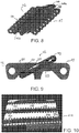
- FIGS. 8 and 9 illustrate a conveyor belt module 112 employing an article mover comprising a flexible band.
- a flexible band 140 straddles the deck 124 of the module.
- Angled pulleys including hubs forming toothed wheels 150 on the sides of the module receive and guide the flexible band 140.
- a first section 140a of the band extends over the top conveying surface 122 and spans the leading end 117 of the deck 124 of the module 112.
- a second section of the band 140b extends over the bottom surface 123 and spans the lag end 116 of the belt.
- An article being conveyed rides on the top section 140a of the band 140.
- the illustrative flexible band 140 comprises a round flexible endless band having a substantially circular cross-section, though other shapes are possible.
- the illustrative band may be formed of polyurethane, silicone, urethane or another suitable material.
- FIG. 10 illustrates a conveyor belt comprising modules 212 employing round flexible bands 240 for moving articles.
- a top section of the flexible band 240 extends laterally across the top conveying surface 222 of the module.
- An article to be conveyed rests on the top section of the flexible band.
- Openings 250 in the deck of the module 212 allow the flexible band 240 to pass to the underside of the module, where it may be trained around wheels.
- the wheels rotate to move the flexible band in one of two directions, causing an article resting on the top section of the flexible band to move towards one side of the module.
- a gear drives one of the wheels to selectively drive the flexible band 240.
- FIG. 11 illustrates a conveyor belt including an article mover for pushing an article towards a side of a module of the conveyor belt.
- the conveyor belt 310 comprises a series of modules 312 hingedly connected together.
- Each module includes an article mover 340, shown in FIG. 12 , comprising a shaft 341, helical blades 342 formed on the shaft and an end wheel 360 for selectively rotating the shaft 341.
- the illustrative article mover comprises three separate helical blades. Conveyed articles ride on the edges of the helical blades at their topmost points.
- Each article mover 340 is rotatably supported between adjacent conveyor belts, or within a single module.
- Each module includes recesses 370 at leading and lagging edges. When hinged together, the recesses form openings for receiving the helical blades.
- the shaft 341 may serve as a hinge rod for lacing adjacent modules together.
- the article movers may alternate in orientation, so that the end wheel 360 is disposed at alternating sides for adjacent modules.
- a gear rack or other suitable mechanism selectively rotates the end wheel 360 to cause rotation of the shaft 341 about an axis of rotation.
- the rotation of the shaft 241 causes rotation of the helical blades 342, which push an article placed thereon towards one side of the module, or towards the middle of the module, or off the module entirely.
Claims (7)
- Förderbandmodul (12), umfassend:Ein Deck (24), dass sich in der Länge von einem ersten Ende zu einem zweiten Ende und in der Breite von einer ersten Seite zu einer zweiten Seite erstreckt und eine Oberseite und eine entgegengesetzte Unterseite aufweist;eine erste Rolle (50), die an der ersten Seite mit dem Deck (24) verbunden ist;eine zweite Rolle (52), die an der zweiten Seite mit dem Deck (24) verbunden ist; ein endloses flexibles Band (40), das um die erste Rolle (50) und die zweite Rolle (52) herum gezogen ist und sich in Querrichtung relativ zur Oberseite des Decks (24) erstreckt, wobei zumindest ein Zahnrad (60, 62) an das Deck (24) angrenzt, wobei zumindest eine der ersten Rolle und der zweiten Rolle mit dem zumindest einen Zahnrad (60, 62) verbunden ist, um die Rolle selektiv anzutreiben, wobei das Zahnrad konfiguriert ist, in ein Antriebsrad einzugreifen, um das Zahnrad selektiv zu rotieren, um dadurch Bewegung des endlosen flexiblen Bandes (40) zu bewirken; unddadurch gekennzeichnet, dass die erste Rolle (50) und die zweite Rolle (52) auf der Oberseite des Decks angeordnet sind, und sich das zumindest eine Zahnrad (60, 62) ab dem Boden der ersten und/oder zweiten Rolle unterhalb des Decks (24) erstreckt; undwobei das Antriebsrad vorzugsweise ein Zahnstangenrad (70) ist.
- Förderbandmodul (12) nach Anspruch 1, das ferner Scharnierelemente (25) umfasst, die sich ab dem ersten Ende und dem zweiten Ende des Decks (24) erstrecken.
- Förderbandmodul (12) nach Anspruch 1, wobei die erste Rolle (50) und die zweite Rolle (52) jeweils eine mittige Nabe (55) und eine Vielzahl von Speichen (54) aufweisen.
- Förderbandmodul (12) nach Anspruch 1, wobei jede Rolle eine vertiefte äußere Oberfläche (57) zur Aufnahme und Führung des Bandes (40) umfasst.
- Förderbandmodul nach Anspruch 1, das ferner eine auf dem ersten Ende oder dem zweiten Ende des Decks geformte Wulst zum Anheben eines Abschnitts des flexiblen Bandes umfasst.
- Förderband, umfassend:Ein erstes und zweites Förderbandmodul (12) nach einem der Ansprüche 2-5 und zumindest nach Anspruch 2;wobei das zweite Förderbandmodul (12) mit dem ersten Förderbandmodul (12) gelenkig verbunden ist; undein Antriebsrad zum Eingreifen in das Zahnrad, um das Zahnrad (60, 62) selektiv zu rotieren und dadurch Bewegung des endlosen flexiblen Bandes (40) zu bewirken.
- Förderband nach Anspruch 6, wobei das Antriebsrad ein Zahnstangenrad (70) ist.
Applications Claiming Priority (2)
| Application Number | Priority Date | Filing Date | Title |
|---|---|---|---|
| US201261669241P | 2012-07-09 | 2012-07-09 | |
| PCT/US2013/049309 WO2014011478A1 (en) | 2012-07-09 | 2013-07-03 | Article diverting conveyor belt |
Publications (3)
| Publication Number | Publication Date |
|---|---|
| EP2870088A1 EP2870088A1 (de) | 2015-05-13 |
| EP2870088A4 EP2870088A4 (de) | 2016-04-27 |
| EP2870088B1 true EP2870088B1 (de) | 2019-05-08 |
Family
ID=49916486
Family Applications (1)
| Application Number | Title | Priority Date | Filing Date |
|---|---|---|---|
| EP13816087.4A Active EP2870088B1 (de) | 2012-07-09 | 2013-07-03 | Förderband mit artikelumleitung |
Country Status (4)
| Country | Link |
|---|---|
| US (1) | US9463931B2 (de) |
| EP (1) | EP2870088B1 (de) |
| CN (1) | CN104470837B (de) |
| WO (1) | WO2014011478A1 (de) |
Families Citing this family (9)
| Publication number | Priority date | Publication date | Assignee | Title |
|---|---|---|---|---|
| US8985304B2 (en) | 2012-07-05 | 2015-03-24 | Laitram, L.L.C. | Cleanable diverter |
| US9302855B2 (en) | 2012-07-05 | 2016-04-05 | Laitram, L.L.C. | Cleanable diverter |
| JP6781147B2 (ja) * | 2014-07-23 | 2020-11-04 | レイトラム,エル.エル.シー. | 清掃可能なダイバータ |
| CN112811079A (zh) * | 2015-07-13 | 2021-05-18 | 莱特莱姆有限公司 | 一种检重器传送带 |
| US9884727B1 (en) | 2016-12-12 | 2018-02-06 | Laitram, L.L.C. | Diverter with roller pushers |
| CA3054597A1 (en) | 2017-03-08 | 2018-09-13 | Robert D. Lundahl | Package sorting transfer module and systems and methods therefor |
| US10532894B2 (en) | 2017-03-10 | 2020-01-14 | Regal Beloit America, Inc. | Modular transfer units, systems, and methods |
| WO2019104095A2 (en) | 2017-11-22 | 2019-05-31 | Regal Beloit America, Inc. | Modular sortation units, systems, and methods |
| US20220280981A1 (en) * | 2019-09-13 | 2022-09-08 | John Bean Technologies Corporation | Conveyor with selective width rejection system |
Citations (1)
| Publication number | Priority date | Publication date | Assignee | Title |
|---|---|---|---|---|
| DE8634099U1 (de) * | 1985-12-20 | 1987-02-12 | Canziani, Francesco, San Macario, Varese, It |
Family Cites Families (21)
| Publication number | Priority date | Publication date | Assignee | Title |
|---|---|---|---|---|
| US3231068A (en) * | 1963-01-07 | 1966-01-25 | Prospect Mfg Co Inc | Article delivery conveyer |
| US4096936A (en) * | 1969-11-03 | 1978-06-27 | Kosan Crisplant A/S | Selectively controllable unloading arrangement for sorting conveyor constructions |
| US5551543A (en) * | 1995-03-27 | 1996-09-03 | Interlake Companies, Inc. | Sorter |
| US5701992A (en) * | 1995-06-02 | 1997-12-30 | Daifuku Co., Ltd. | Sorting equipment |
| JP2002293425A (ja) | 1998-12-24 | 2002-10-09 | Techno Wave:Kk | コンベア装置 |
| JP4896308B2 (ja) | 2001-07-06 | 2012-03-14 | 積水化学工業株式会社 | 搬送コンベア装置 |
| US6705452B2 (en) | 2002-05-13 | 2004-03-16 | Laitram, L.L.C. | Article-diverting conveyor belt and modules |
| US6802412B2 (en) * | 2002-11-19 | 2004-10-12 | The Laitram Corporation | Conveyor with a motorized transport element |
| US7080725B2 (en) * | 2002-12-03 | 2006-07-25 | Sanki Engineering Co., Ltd. | Sorting conveyor provided with cross sorter |
| DE10340868B4 (de) * | 2003-09-04 | 2005-09-29 | Siemens Ag | Fördersystem, insbesondere eine Flughafengepäckförderanlage, für zum Transport von Stückgut dienenden Behältern |
| CN101558000B (zh) * | 2006-01-26 | 2012-07-18 | 莱特拉姆有限责任公司 | 用于使物体转向的系统和方法 |
| US7506751B2 (en) * | 2006-01-26 | 2009-03-24 | Laitram, L.L.C. | Conveyor systems for diverting objects |
| US7360641B1 (en) | 2007-04-13 | 2008-04-22 | Laitram, L.L.C. | Conveyor belt having rollers that displace objects |
| CN101497400A (zh) * | 2008-02-01 | 2009-08-05 | 贵阳普天物流技术股份有限公司 | 一种标准箱体的分拣方法及装置 |
| WO2010008756A1 (en) * | 2008-06-23 | 2010-01-21 | Laitram, L.L.C. | Apparatus and method for selectively actuating moving conveyor rollers |
| US20100006393A1 (en) * | 2008-07-14 | 2010-01-14 | Jervis B. Webb Company | Diverter Assembly |
| WO2010016805A1 (en) | 2008-08-06 | 2010-02-11 | Pteris Global Ltd. | High speed diverter |
| EP2165948B1 (de) * | 2008-09-17 | 2014-11-12 | Ammeraal Beltech Modular A/S | Kettenglied für eine modulare Förderkette mit einem Quergurt |
| US9145270B2 (en) * | 2009-07-06 | 2015-09-29 | Gebo Packaging Solutions France | Apparatus for handling and accumulating articles in a buffer area |
| CN101870374B (zh) * | 2010-06-24 | 2011-11-02 | 江阴纳尔捷机器人有限公司 | 物料分流机构 |
| US8684169B2 (en) * | 2010-08-31 | 2014-04-01 | Itoh Denki Co., Ltd. | Transfer device |
-
2013
- 2013-07-03 US US14/410,142 patent/US9463931B2/en active Active
- 2013-07-03 CN CN201380036399.2A patent/CN104470837B/zh active Active
- 2013-07-03 EP EP13816087.4A patent/EP2870088B1/de active Active
- 2013-07-03 WO PCT/US2013/049309 patent/WO2014011478A1/en active Application Filing
Patent Citations (1)
| Publication number | Priority date | Publication date | Assignee | Title |
|---|---|---|---|---|
| DE8634099U1 (de) * | 1985-12-20 | 1987-02-12 | Canziani, Francesco, San Macario, Varese, It |
Also Published As
| Publication number | Publication date |
|---|---|
| CN104470837A (zh) | 2015-03-25 |
| WO2014011478A1 (en) | 2014-01-16 |
| US20150321852A1 (en) | 2015-11-12 |
| EP2870088A1 (de) | 2015-05-13 |
| CN104470837B (zh) | 2016-08-31 |
| US9463931B2 (en) | 2016-10-11 |
| EP2870088A4 (de) | 2016-04-27 |
Similar Documents
| Publication | Publication Date | Title |
|---|---|---|
| EP2870088B1 (de) | Förderband mit artikelumleitung | |
| EP3116815B1 (de) | Förderband mit artikelumleitung | |
| EP3283408B1 (de) | Fördersystem mit transportbändern | |
| EP2165948B1 (de) | Kettenglied für eine modulare Förderkette mit einem Quergurt | |
| DK2621835T3 (en) | Conveyor, belt and module, which has wheels that are oriented in several directions | |
| ES2763555T3 (es) | Cinta de transportador | |
| EP2656987B1 (de) | Modulare und selbsteinrastende kunststoffborstenbürste | |
| US20150259156A1 (en) | D wheel transfer device and method | |
| US9434546B2 (en) | End drive for a conveyor, conveyor provided with an end drive, and drive gear for an end drive | |
| EP2911956B1 (de) | Endantrieb für einen förderer und förderer mit einem endantrieb | |
| EP1826159A1 (de) | Fördersystem | |
| KR101082596B1 (ko) | 떡 절단장치 | |
| EP2157036B1 (de) | Drückgurt | |
| KR102629097B1 (ko) | 컨베이어 드라이브 시스템 | |
| US20090050449A1 (en) | Conveying system | |
| MX2010005538A (es) | Liston separador de desplamiento positivo. | |
| US20080035450A1 (en) | Slat driven positive displacement sorter | |
| CN104470833B (zh) | 包括垫塞模块的输送带 | |
| CA1111077A (en) | Sod harvesting machine having means for conveying and stacking sod pads | |
| JPH0369243B2 (de) |
Legal Events
| Date | Code | Title | Description |
|---|---|---|---|
| PUAI | Public reference made under article 153(3) epc to a published international application that has entered the european phase |
Free format text: ORIGINAL CODE: 0009012 |
|
| 17P | Request for examination filed |
Effective date: 20141211 |
|
| AK | Designated contracting states |
Kind code of ref document: A1 Designated state(s): AL AT BE BG CH CY CZ DE DK EE ES FI FR GB GR HR HU IE IS IT LI LT LU LV MC MK MT NL NO PL PT RO RS SE SI SK SM TR |
|
| AX | Request for extension of the european patent |
Extension state: BA ME |
|
| DAX | Request for extension of the european patent (deleted) | ||
| RA4 | Supplementary search report drawn up and despatched (corrected) |
Effective date: 20160324 |
|
| RIC1 | Information provided on ipc code assigned before grant |
Ipc: B65G 47/46 20060101ALI20160318BHEP Ipc: B65G 47/52 20060101AFI20160318BHEP Ipc: B65G 15/30 20060101ALI20160318BHEP |
|
| STAA | Information on the status of an ep patent application or granted ep patent |
Free format text: STATUS: EXAMINATION IS IN PROGRESS |
|
| 17Q | First examination report despatched |
Effective date: 20170623 |
|
| GRAP | Despatch of communication of intention to grant a patent |
Free format text: ORIGINAL CODE: EPIDOSNIGR1 |
|
| STAA | Information on the status of an ep patent application or granted ep patent |
Free format text: STATUS: GRANT OF PATENT IS INTENDED |
|
| INTG | Intention to grant announced |
Effective date: 20181115 |
|
| GRAS | Grant fee paid |
Free format text: ORIGINAL CODE: EPIDOSNIGR3 |
|
| GRAA | (expected) grant |
Free format text: ORIGINAL CODE: 0009210 |
|
| STAA | Information on the status of an ep patent application or granted ep patent |
Free format text: STATUS: THE PATENT HAS BEEN GRANTED |
|
| AK | Designated contracting states |
Kind code of ref document: B1 Designated state(s): AL AT BE BG CH CY CZ DE DK EE ES FI FR GB GR HR HU IE IS IT LI LT LU LV MC MK MT NL NO PL PT RO RS SE SI SK SM TR |
|
| REG | Reference to a national code |
Ref country code: GB Ref legal event code: FG4D |
|
| REG | Reference to a national code |
Ref country code: CH Ref legal event code: EP Ref country code: AT Ref legal event code: REF Ref document number: 1129810 Country of ref document: AT Kind code of ref document: T Effective date: 20190515 |
|
| REG | Reference to a national code |
Ref country code: IE Ref legal event code: FG4D |
|
| REG | Reference to a national code |
Ref country code: DE Ref legal event code: R096 Ref document number: 602013055163 Country of ref document: DE |
|
| REG | Reference to a national code |
Ref country code: NL Ref legal event code: MP Effective date: 20190508 |
|
| REG | Reference to a national code |
Ref country code: LT Ref legal event code: MG4D |
|
| PG25 | Lapsed in a contracting state [announced via postgrant information from national office to epo] |
Ref country code: HR Free format text: LAPSE BECAUSE OF FAILURE TO SUBMIT A TRANSLATION OF THE DESCRIPTION OR TO PAY THE FEE WITHIN THE PRESCRIBED TIME-LIMIT Effective date: 20190508 Ref country code: NL Free format text: LAPSE BECAUSE OF FAILURE TO SUBMIT A TRANSLATION OF THE DESCRIPTION OR TO PAY THE FEE WITHIN THE PRESCRIBED TIME-LIMIT Effective date: 20190508 Ref country code: FI Free format text: LAPSE BECAUSE OF FAILURE TO SUBMIT A TRANSLATION OF THE DESCRIPTION OR TO PAY THE FEE WITHIN THE PRESCRIBED TIME-LIMIT Effective date: 20190508 Ref country code: LT Free format text: LAPSE BECAUSE OF FAILURE TO SUBMIT A TRANSLATION OF THE DESCRIPTION OR TO PAY THE FEE WITHIN THE PRESCRIBED TIME-LIMIT Effective date: 20190508 Ref country code: ES Free format text: LAPSE BECAUSE OF FAILURE TO SUBMIT A TRANSLATION OF THE DESCRIPTION OR TO PAY THE FEE WITHIN THE PRESCRIBED TIME-LIMIT Effective date: 20190508 Ref country code: NO Free format text: LAPSE BECAUSE OF FAILURE TO SUBMIT A TRANSLATION OF THE DESCRIPTION OR TO PAY THE FEE WITHIN THE PRESCRIBED TIME-LIMIT Effective date: 20190808 Ref country code: PT Free format text: LAPSE BECAUSE OF FAILURE TO SUBMIT A TRANSLATION OF THE DESCRIPTION OR TO PAY THE FEE WITHIN THE PRESCRIBED TIME-LIMIT Effective date: 20190908 Ref country code: SE Free format text: LAPSE BECAUSE OF FAILURE TO SUBMIT A TRANSLATION OF THE DESCRIPTION OR TO PAY THE FEE WITHIN THE PRESCRIBED TIME-LIMIT Effective date: 20190508 Ref country code: AL Free format text: LAPSE BECAUSE OF FAILURE TO SUBMIT A TRANSLATION OF THE DESCRIPTION OR TO PAY THE FEE WITHIN THE PRESCRIBED TIME-LIMIT Effective date: 20190508 |
|
| PG25 | Lapsed in a contracting state [announced via postgrant information from national office to epo] |
Ref country code: GR Free format text: LAPSE BECAUSE OF FAILURE TO SUBMIT A TRANSLATION OF THE DESCRIPTION OR TO PAY THE FEE WITHIN THE PRESCRIBED TIME-LIMIT Effective date: 20190809 Ref country code: LV Free format text: LAPSE BECAUSE OF FAILURE TO SUBMIT A TRANSLATION OF THE DESCRIPTION OR TO PAY THE FEE WITHIN THE PRESCRIBED TIME-LIMIT Effective date: 20190508 Ref country code: BG Free format text: LAPSE BECAUSE OF FAILURE TO SUBMIT A TRANSLATION OF THE DESCRIPTION OR TO PAY THE FEE WITHIN THE PRESCRIBED TIME-LIMIT Effective date: 20190808 Ref country code: RS Free format text: LAPSE BECAUSE OF FAILURE TO SUBMIT A TRANSLATION OF THE DESCRIPTION OR TO PAY THE FEE WITHIN THE PRESCRIBED TIME-LIMIT Effective date: 20190508 |
|
| REG | Reference to a national code |
Ref country code: AT Ref legal event code: MK05 Ref document number: 1129810 Country of ref document: AT Kind code of ref document: T Effective date: 20190508 |
|
| PG25 | Lapsed in a contracting state [announced via postgrant information from national office to epo] |
Ref country code: AT Free format text: LAPSE BECAUSE OF FAILURE TO SUBMIT A TRANSLATION OF THE DESCRIPTION OR TO PAY THE FEE WITHIN THE PRESCRIBED TIME-LIMIT Effective date: 20190508 Ref country code: EE Free format text: LAPSE BECAUSE OF FAILURE TO SUBMIT A TRANSLATION OF THE DESCRIPTION OR TO PAY THE FEE WITHIN THE PRESCRIBED TIME-LIMIT Effective date: 20190508 Ref country code: RO Free format text: LAPSE BECAUSE OF FAILURE TO SUBMIT A TRANSLATION OF THE DESCRIPTION OR TO PAY THE FEE WITHIN THE PRESCRIBED TIME-LIMIT Effective date: 20190508 Ref country code: CZ Free format text: LAPSE BECAUSE OF FAILURE TO SUBMIT A TRANSLATION OF THE DESCRIPTION OR TO PAY THE FEE WITHIN THE PRESCRIBED TIME-LIMIT Effective date: 20190508 Ref country code: SK Free format text: LAPSE BECAUSE OF FAILURE TO SUBMIT A TRANSLATION OF THE DESCRIPTION OR TO PAY THE FEE WITHIN THE PRESCRIBED TIME-LIMIT Effective date: 20190508 Ref country code: DK Free format text: LAPSE BECAUSE OF FAILURE TO SUBMIT A TRANSLATION OF THE DESCRIPTION OR TO PAY THE FEE WITHIN THE PRESCRIBED TIME-LIMIT Effective date: 20190508 |
|
| REG | Reference to a national code |
Ref country code: DE Ref legal event code: R097 Ref document number: 602013055163 Country of ref document: DE |
|
| PG25 | Lapsed in a contracting state [announced via postgrant information from national office to epo] |
Ref country code: SM Free format text: LAPSE BECAUSE OF FAILURE TO SUBMIT A TRANSLATION OF THE DESCRIPTION OR TO PAY THE FEE WITHIN THE PRESCRIBED TIME-LIMIT Effective date: 20190508 Ref country code: IT Free format text: LAPSE BECAUSE OF FAILURE TO SUBMIT A TRANSLATION OF THE DESCRIPTION OR TO PAY THE FEE WITHIN THE PRESCRIBED TIME-LIMIT Effective date: 20190508 Ref country code: MC Free format text: LAPSE BECAUSE OF FAILURE TO SUBMIT A TRANSLATION OF THE DESCRIPTION OR TO PAY THE FEE WITHIN THE PRESCRIBED TIME-LIMIT Effective date: 20190508 |
|
| REG | Reference to a national code |
Ref country code: CH Ref legal event code: PL |
|
| PLBE | No opposition filed within time limit |
Free format text: ORIGINAL CODE: 0009261 |
|
| STAA | Information on the status of an ep patent application or granted ep patent |
Free format text: STATUS: NO OPPOSITION FILED WITHIN TIME LIMIT |
|
| PG25 | Lapsed in a contracting state [announced via postgrant information from national office to epo] |
Ref country code: TR Free format text: LAPSE BECAUSE OF FAILURE TO SUBMIT A TRANSLATION OF THE DESCRIPTION OR TO PAY THE FEE WITHIN THE PRESCRIBED TIME-LIMIT Effective date: 20190508 |
|
| 26N | No opposition filed |
Effective date: 20200211 |
|
| REG | Reference to a national code |
Ref country code: BE Ref legal event code: MM Effective date: 20190731 |
|
| PG25 | Lapsed in a contracting state [announced via postgrant information from national office to epo] |
Ref country code: PL Free format text: LAPSE BECAUSE OF FAILURE TO SUBMIT A TRANSLATION OF THE DESCRIPTION OR TO PAY THE FEE WITHIN THE PRESCRIBED TIME-LIMIT Effective date: 20190508 |
|
| PG25 | Lapsed in a contracting state [announced via postgrant information from national office to epo] |
Ref country code: BE Free format text: LAPSE BECAUSE OF NON-PAYMENT OF DUE FEES Effective date: 20190731 Ref country code: CH Free format text: LAPSE BECAUSE OF NON-PAYMENT OF DUE FEES Effective date: 20190731 Ref country code: LI Free format text: LAPSE BECAUSE OF NON-PAYMENT OF DUE FEES Effective date: 20190731 Ref country code: LU Free format text: LAPSE BECAUSE OF NON-PAYMENT OF DUE FEES Effective date: 20190703 Ref country code: SI Free format text: LAPSE BECAUSE OF FAILURE TO SUBMIT A TRANSLATION OF THE DESCRIPTION OR TO PAY THE FEE WITHIN THE PRESCRIBED TIME-LIMIT Effective date: 20190508 |
|
| PG25 | Lapsed in a contracting state [announced via postgrant information from national office to epo] |
Ref country code: FR Free format text: LAPSE BECAUSE OF NON-PAYMENT OF DUE FEES Effective date: 20190708 |
|
| PG25 | Lapsed in a contracting state [announced via postgrant information from national office to epo] |
Ref country code: IE Free format text: LAPSE BECAUSE OF NON-PAYMENT OF DUE FEES Effective date: 20190703 |
|
| PG25 | Lapsed in a contracting state [announced via postgrant information from national office to epo] |
Ref country code: CY Free format text: LAPSE BECAUSE OF FAILURE TO SUBMIT A TRANSLATION OF THE DESCRIPTION OR TO PAY THE FEE WITHIN THE PRESCRIBED TIME-LIMIT Effective date: 20190508 |
|
| PG25 | Lapsed in a contracting state [announced via postgrant information from national office to epo] |
Ref country code: IS Free format text: LAPSE BECAUSE OF FAILURE TO SUBMIT A TRANSLATION OF THE DESCRIPTION OR TO PAY THE FEE WITHIN THE PRESCRIBED TIME-LIMIT Effective date: 20190908 |
|
| PG25 | Lapsed in a contracting state [announced via postgrant information from national office to epo] |
Ref country code: MT Free format text: LAPSE BECAUSE OF FAILURE TO SUBMIT A TRANSLATION OF THE DESCRIPTION OR TO PAY THE FEE WITHIN THE PRESCRIBED TIME-LIMIT Effective date: 20190508 Ref country code: HU Free format text: LAPSE BECAUSE OF FAILURE TO SUBMIT A TRANSLATION OF THE DESCRIPTION OR TO PAY THE FEE WITHIN THE PRESCRIBED TIME-LIMIT; INVALID AB INITIO Effective date: 20130703 |
|
| REG | Reference to a national code |
Ref country code: DE Ref legal event code: R082 Ref document number: 602013055163 Country of ref document: DE Representative=s name: HAVERKAMP PATENTANWAELTE PARTG MBB, DE |
|
| PG25 | Lapsed in a contracting state [announced via postgrant information from national office to epo] |
Ref country code: MK Free format text: LAPSE BECAUSE OF FAILURE TO SUBMIT A TRANSLATION OF THE DESCRIPTION OR TO PAY THE FEE WITHIN THE PRESCRIBED TIME-LIMIT Effective date: 20190508 |
|
| PGFP | Annual fee paid to national office [announced via postgrant information from national office to epo] |
Ref country code: GB Payment date: 20230614 Year of fee payment: 11 |
|
| PGFP | Annual fee paid to national office [announced via postgrant information from national office to epo] |
Ref country code: DE Payment date: 20230614 Year of fee payment: 11 |