EP2869999B1 - Sicherheitsvorrichtungen - Google Patents
Sicherheitsvorrichtungen Download PDFInfo
- Publication number
- EP2869999B1 EP2869999B1 EP13735383.5A EP13735383A EP2869999B1 EP 2869999 B1 EP2869999 B1 EP 2869999B1 EP 13735383 A EP13735383 A EP 13735383A EP 2869999 B1 EP2869999 B1 EP 2869999B1
- Authority
- EP
- European Patent Office
- Prior art keywords
- regions
- pattern
- region
- obstruction
- group
- Prior art date
- Legal status (The legal status is an assumption and is not a legal conclusion. Google has not performed a legal analysis and makes no representation as to the accuracy of the status listed.)
- Active
Links
Images








Classifications
-
- B—PERFORMING OPERATIONS; TRANSPORTING
- B44—DECORATIVE ARTS
- B44F—SPECIAL DESIGNS OR PICTURES
- B44F1/00—Designs or pictures characterised by special or unusual light effects
- B44F1/08—Designs or pictures characterised by special or unusual light effects characterised by colour effects
- B44F1/10—Changing, amusing, or secret pictures
-
- B—PERFORMING OPERATIONS; TRANSPORTING
- B42—BOOKBINDING; ALBUMS; FILES; SPECIAL PRINTED MATTER
- B42D—BOOKS; BOOK COVERS; LOOSE LEAVES; PRINTED MATTER CHARACTERISED BY IDENTIFICATION OR SECURITY FEATURES; PRINTED MATTER OF SPECIAL FORMAT OR STYLE NOT OTHERWISE PROVIDED FOR; DEVICES FOR USE THEREWITH AND NOT OTHERWISE PROVIDED FOR; MOVABLE-STRIP WRITING OR READING APPARATUS
- B42D25/00—Information-bearing cards or sheet-like structures characterised by identification or security features; Manufacture thereof
- B42D25/20—Information-bearing cards or sheet-like structures characterised by identification or security features; Manufacture thereof characterised by a particular use or purpose
- B42D25/29—Securities; Bank notes
-
- B—PERFORMING OPERATIONS; TRANSPORTING
- B42—BOOKBINDING; ALBUMS; FILES; SPECIAL PRINTED MATTER
- B42D—BOOKS; BOOK COVERS; LOOSE LEAVES; PRINTED MATTER CHARACTERISED BY IDENTIFICATION OR SECURITY FEATURES; PRINTED MATTER OF SPECIAL FORMAT OR STYLE NOT OTHERWISE PROVIDED FOR; DEVICES FOR USE THEREWITH AND NOT OTHERWISE PROVIDED FOR; MOVABLE-STRIP WRITING OR READING APPARATUS
- B42D25/00—Information-bearing cards or sheet-like structures characterised by identification or security features; Manufacture thereof
-
- B—PERFORMING OPERATIONS; TRANSPORTING
- B42—BOOKBINDING; ALBUMS; FILES; SPECIAL PRINTED MATTER
- B42D—BOOKS; BOOK COVERS; LOOSE LEAVES; PRINTED MATTER CHARACTERISED BY IDENTIFICATION OR SECURITY FEATURES; PRINTED MATTER OF SPECIAL FORMAT OR STYLE NOT OTHERWISE PROVIDED FOR; DEVICES FOR USE THEREWITH AND NOT OTHERWISE PROVIDED FOR; MOVABLE-STRIP WRITING OR READING APPARATUS
- B42D25/00—Information-bearing cards or sheet-like structures characterised by identification or security features; Manufacture thereof
- B42D25/20—Information-bearing cards or sheet-like structures characterised by identification or security features; Manufacture thereof characterised by a particular use or purpose
-
- B—PERFORMING OPERATIONS; TRANSPORTING
- B42—BOOKBINDING; ALBUMS; FILES; SPECIAL PRINTED MATTER
- B42D—BOOKS; BOOK COVERS; LOOSE LEAVES; PRINTED MATTER CHARACTERISED BY IDENTIFICATION OR SECURITY FEATURES; PRINTED MATTER OF SPECIAL FORMAT OR STYLE NOT OTHERWISE PROVIDED FOR; DEVICES FOR USE THEREWITH AND NOT OTHERWISE PROVIDED FOR; MOVABLE-STRIP WRITING OR READING APPARATUS
- B42D25/00—Information-bearing cards or sheet-like structures characterised by identification or security features; Manufacture thereof
- B42D25/30—Identification or security features, e.g. for preventing forgery
- B42D25/342—Moiré effects
-
- B—PERFORMING OPERATIONS; TRANSPORTING
- B42—BOOKBINDING; ALBUMS; FILES; SPECIAL PRINTED MATTER
- B42D—BOOKS; BOOK COVERS; LOOSE LEAVES; PRINTED MATTER CHARACTERISED BY IDENTIFICATION OR SECURITY FEATURES; PRINTED MATTER OF SPECIAL FORMAT OR STYLE NOT OTHERWISE PROVIDED FOR; DEVICES FOR USE THEREWITH AND NOT OTHERWISE PROVIDED FOR; MOVABLE-STRIP WRITING OR READING APPARATUS
- B42D25/00—Information-bearing cards or sheet-like structures characterised by identification or security features; Manufacture thereof
- B42D25/30—Identification or security features, e.g. for preventing forgery
- B42D25/351—Translucent or partly translucent parts, e.g. windows
-
- B—PERFORMING OPERATIONS; TRANSPORTING
- B42—BOOKBINDING; ALBUMS; FILES; SPECIAL PRINTED MATTER
- B42D—BOOKS; BOOK COVERS; LOOSE LEAVES; PRINTED MATTER CHARACTERISED BY IDENTIFICATION OR SECURITY FEATURES; PRINTED MATTER OF SPECIAL FORMAT OR STYLE NOT OTHERWISE PROVIDED FOR; DEVICES FOR USE THEREWITH AND NOT OTHERWISE PROVIDED FOR; MOVABLE-STRIP WRITING OR READING APPARATUS
- B42D25/00—Information-bearing cards or sheet-like structures characterised by identification or security features; Manufacture thereof
- B42D25/30—Identification or security features, e.g. for preventing forgery
- B42D25/355—Security threads
-
- B—PERFORMING OPERATIONS; TRANSPORTING
- B42—BOOKBINDING; ALBUMS; FILES; SPECIAL PRINTED MATTER
- B42D—BOOKS; BOOK COVERS; LOOSE LEAVES; PRINTED MATTER CHARACTERISED BY IDENTIFICATION OR SECURITY FEATURES; PRINTED MATTER OF SPECIAL FORMAT OR STYLE NOT OTHERWISE PROVIDED FOR; DEVICES FOR USE THEREWITH AND NOT OTHERWISE PROVIDED FOR; MOVABLE-STRIP WRITING OR READING APPARATUS
- B42D25/00—Information-bearing cards or sheet-like structures characterised by identification or security features; Manufacture thereof
- B42D25/30—Identification or security features, e.g. for preventing forgery
- B42D25/36—Identification or security features, e.g. for preventing forgery comprising special materials
- B42D25/369—Magnetised or magnetisable materials
-
- B—PERFORMING OPERATIONS; TRANSPORTING
- B42—BOOKBINDING; ALBUMS; FILES; SPECIAL PRINTED MATTER
- B42D—BOOKS; BOOK COVERS; LOOSE LEAVES; PRINTED MATTER CHARACTERISED BY IDENTIFICATION OR SECURITY FEATURES; PRINTED MATTER OF SPECIAL FORMAT OR STYLE NOT OTHERWISE PROVIDED FOR; DEVICES FOR USE THEREWITH AND NOT OTHERWISE PROVIDED FOR; MOVABLE-STRIP WRITING OR READING APPARATUS
- B42D25/00—Information-bearing cards or sheet-like structures characterised by identification or security features; Manufacture thereof
- B42D25/30—Identification or security features, e.g. for preventing forgery
- B42D25/36—Identification or security features, e.g. for preventing forgery comprising special materials
- B42D25/373—Metallic materials
-
- B—PERFORMING OPERATIONS; TRANSPORTING
- B42—BOOKBINDING; ALBUMS; FILES; SPECIAL PRINTED MATTER
- B42D—BOOKS; BOOK COVERS; LOOSE LEAVES; PRINTED MATTER CHARACTERISED BY IDENTIFICATION OR SECURITY FEATURES; PRINTED MATTER OF SPECIAL FORMAT OR STYLE NOT OTHERWISE PROVIDED FOR; DEVICES FOR USE THEREWITH AND NOT OTHERWISE PROVIDED FOR; MOVABLE-STRIP WRITING OR READING APPARATUS
- B42D25/00—Information-bearing cards or sheet-like structures characterised by identification or security features; Manufacture thereof
- B42D25/30—Identification or security features, e.g. for preventing forgery
- B42D25/36—Identification or security features, e.g. for preventing forgery comprising special materials
- B42D25/378—Special inks
-
- B—PERFORMING OPERATIONS; TRANSPORTING
- B42—BOOKBINDING; ALBUMS; FILES; SPECIAL PRINTED MATTER
- B42D—BOOKS; BOOK COVERS; LOOSE LEAVES; PRINTED MATTER CHARACTERISED BY IDENTIFICATION OR SECURITY FEATURES; PRINTED MATTER OF SPECIAL FORMAT OR STYLE NOT OTHERWISE PROVIDED FOR; DEVICES FOR USE THEREWITH AND NOT OTHERWISE PROVIDED FOR; MOVABLE-STRIP WRITING OR READING APPARATUS
- B42D25/00—Information-bearing cards or sheet-like structures characterised by identification or security features; Manufacture thereof
- B42D25/30—Identification or security features, e.g. for preventing forgery
- B42D25/36—Identification or security features, e.g. for preventing forgery comprising special materials
- B42D25/378—Special inks
- B42D25/387—Special inks absorbing or reflecting ultraviolet light
-
- B—PERFORMING OPERATIONS; TRANSPORTING
- B42—BOOKBINDING; ALBUMS; FILES; SPECIAL PRINTED MATTER
- B42D—BOOKS; BOOK COVERS; LOOSE LEAVES; PRINTED MATTER CHARACTERISED BY IDENTIFICATION OR SECURITY FEATURES; PRINTED MATTER OF SPECIAL FORMAT OR STYLE NOT OTHERWISE PROVIDED FOR; DEVICES FOR USE THEREWITH AND NOT OTHERWISE PROVIDED FOR; MOVABLE-STRIP WRITING OR READING APPARATUS
- B42D25/00—Information-bearing cards or sheet-like structures characterised by identification or security features; Manufacture thereof
- B42D25/30—Identification or security features, e.g. for preventing forgery
- B42D25/36—Identification or security features, e.g. for preventing forgery comprising special materials
- B42D25/378—Special inks
- B42D25/391—Special inks absorbing or reflecting polarised light
-
- B—PERFORMING OPERATIONS; TRANSPORTING
- B42—BOOKBINDING; ALBUMS; FILES; SPECIAL PRINTED MATTER
- B42D—BOOKS; BOOK COVERS; LOOSE LEAVES; PRINTED MATTER CHARACTERISED BY IDENTIFICATION OR SECURITY FEATURES; PRINTED MATTER OF SPECIAL FORMAT OR STYLE NOT OTHERWISE PROVIDED FOR; DEVICES FOR USE THEREWITH AND NOT OTHERWISE PROVIDED FOR; MOVABLE-STRIP WRITING OR READING APPARATUS
- B42D25/00—Information-bearing cards or sheet-like structures characterised by identification or security features; Manufacture thereof
- B42D25/40—Manufacture
- B42D25/405—Marking
- B42D25/43—Marking by removal of material
-
- B—PERFORMING OPERATIONS; TRANSPORTING
- B42—BOOKBINDING; ALBUMS; FILES; SPECIAL PRINTED MATTER
- B42D—BOOKS; BOOK COVERS; LOOSE LEAVES; PRINTED MATTER CHARACTERISED BY IDENTIFICATION OR SECURITY FEATURES; PRINTED MATTER OF SPECIAL FORMAT OR STYLE NOT OTHERWISE PROVIDED FOR; DEVICES FOR USE THEREWITH AND NOT OTHERWISE PROVIDED FOR; MOVABLE-STRIP WRITING OR READING APPARATUS
- B42D25/00—Information-bearing cards or sheet-like structures characterised by identification or security features; Manufacture thereof
- B42D25/40—Manufacture
- B42D25/405—Marking
- B42D25/43—Marking by removal of material
- B42D25/435—Marking by removal of material using electromagnetic radiation, e.g. laser
-
- G—PHYSICS
- G02—OPTICS
- G02B—OPTICAL ELEMENTS, SYSTEMS OR APPARATUS
- G02B5/00—Optical elements other than lenses
- G02B5/12—Reflex reflectors
- G02B5/122—Reflex reflectors cube corner, trihedral or triple reflector type
- G02B5/124—Reflex reflectors cube corner, trihedral or triple reflector type plural reflecting elements forming part of a unitary plate or sheet
-
- G—PHYSICS
- G07—CHECKING-DEVICES
- G07D—HANDLING OF COINS OR VALUABLE PAPERS, e.g. TESTING, SORTING BY DENOMINATIONS, COUNTING, DISPENSING, CHANGING OR DEPOSITING
- G07D7/00—Testing specially adapted to determine the identity or genuineness of valuable papers or for segregating those which are unacceptable, e.g. banknotes that are alien to a currency
- G07D7/003—Testing specially adapted to determine the identity or genuineness of valuable papers or for segregating those which are unacceptable, e.g. banknotes that are alien to a currency using security elements
-
- B42D2033/18—
-
- B42D2035/14—
-
- B42D2035/16—
-
- B42D2035/26—
-
- B42D2035/36—
Definitions
- This invention relates to security devices, as claimed in claim 1, such as may be used as a mark of authenticity associated with an object of value, as claimed in claims 21 to 23, and such as a security document including banknotes, passports, certificates, licences and the like.
- Objects of value, and particularly documents of value are frequently the target of counterfeiters and persons wishing to make fraudulent copies thereof and/or changes to any data contained therein.
- Typical such objects are provided with a number of visible security devices for checking the authenticity of the object. Examples include features based on one or more patterns such as microtext, fine line patterns, latent images, venetian blind devices, lenticular devices, moire interference devices and moire magnification devices, each of which generates a secure visual effect.
- Other known security devices include holograms, watermarks, embossings, perforations and the use of colour-shifting or luminescent / fluorescent inks. Common to all such devices is that the visual effect exhibited by the device is extremely difficult, or impossible, to copy using available reproduction techniques such as photocopying. Security devices exhibiting non-visible effects such as magnetic materials may also be employed.
- Security devices which have an optically variable appearance - i.e. their appearance is different at different angles of view - have been found to be particularly effective since the authenticity of the device can be readily checked by tilting or rotating the device and observing the expected change in appearance. Photocopies of such devices will, on the other hand, have a static appearance which does not change as the viewing position is altered.
- the venetian blind device already mentioned above.
- This comprises two patterns, e.g. printed line patterns, arranged on either side of a transparent spacer layer.
- the line patterns are aligned along substantially the same direction as one another.
- the two sets of lines When the device is viewed in transmission, at some angles (between the device normal and the observer), the two sets of lines will appear to tessellate with one another, obstructing the passage of light through the device and causing it to appear dark. At other angles, the two sets of lines will become aligned with one another to a greater or lesser extent, allowing the passage of light through the device and causing it to appear relatively bright.
- a security device which does not form part of the present invention, comprises a first pattern of elements and a second, overlapping, pattern of elements spaced by a transparent layer, the first and second patterns in combination obstructing the passage of light transmitted to a viewer through the device to a varying degree depending on the viewing position, wherein the first and second patterns of elements are configured such that a first region of the device exhibits a maximum rate of change in the degree of obstruction with tilt angle when the device is tilted relative to the viewer about a first tilt axis, and a second region of the device exhibits a maximum rate of change in the degree of obstruction with tilt angle when the device is tilted relative to the viewer about a second tilt axis which is not parallel to the first tilt axis.
- the degree of obstruction exhibited by said device not forming part of the present invention, at any viewing angle can manifest itself in a number of different ways.
- the pattern elements will be of greater optical density than the transparent layer.
- the pattern elements may be substantially opaque in which case the degree of obstruction would correspond to an apparent darkness level of the region.
- the pattern elements could be semi-transparent and coloured, in which case a greater degree of obstruction could appear as an increase in colour intensity or as a change in tone or hue if elements of more than one colour are present.
- the description below will often refer to the "darkness" of the device or a region thereof, and it should be understood that this is only one example of how the degree of obstruction may affect the device's appearance.
- the light "transmitted through” said device need not be transmitted from a light source on one side of the device through to a viewer on the other side.
- one side of the device may be provided with a reflective surface such that light from a light source on one side of the device can be transmitted through the device and reflected back through the device to an observer on the same side as the light source.
- the rate of change in a region's obstruction level with tilt angle determines how much the appearance of a region will change when the device is tilted (i.e. the viewing position moves towards or away from the normal) by a certain amount.
- the rate of change is affected by various factors including the arrangement of the patterns as will be described below.
- the second region will remain relatively unchanged in appearance.
- the behaviour of the two regions will be reversed.
- the visual effects exhibited by the device will be different depending on the direction of tilt, which increased complexity enhances the security level of the device.
- the contrast between the two regions that will be apparent at many angles of view additionally enables the device to be used to convey information, e.g. numbers, text, graphics, etc.
- the regions are configured such that when said device, not forming part of the present invention, is tilted about the first tilt axis, the second region of the device exhibits substantially no change in the degree of obstruction.
- one region remains substantially static and unchanged in appearance when the device is tilted in such a way that the other region displays it maximum rate of variation.
- both regions could display some variation when the device is tilted about the first tilt axis, although the variation rate of the second region is preferably very slow in comparison.
- the first region of the device will now show substantially no variation in its appearance, or very little.
- the two tilt axes could be at any non-zero angle to one another, but preferably the intervening angle is sufficiently large such that when the device is tilted about the first axis, any component of tilt about the second tilt axis resulting from the movement is small.
- the angle between the axes may be around 45 degrees or greater.
- the first and second tilt axes are substantially perpendicular to one another (e.g. 85 to 95 degrees).
- the two regions of said device could have different pattern configurations such that their appearance is different from one another when the device is viewed normally.
- the first and second regions exhibit substantially no contrast between them when the device is viewed from the normal position.
- any boundary between the regions can be substantially concealed such that the presence of the two different regions is not readily apparent when the device is viewed from the normal but is revealed when the device is tilted.
- the region such that the lateral offset between the first and second patterns is the same in each of the first and second regions.
- the lateral offset between the first and second patterns is such that the elements of the first pattern are complementary to those of the second pattern, being located in between the elements of the second pattern, whereby from the normal viewing position, the first and second regions each exhibit their maximum degree of obstruction.
- the two regions of the device appear dark when viewed normally.
- the lateral offset between the first and second patterns is such that the elements of the first pattern are non-complementary to those of the second pattern, being located directly in line with the elements of the second pattern, whereby from the normal viewing position, the first and second regions each exhibit their minimum degree of obstruction.
- the two regions of the device appear light when viewed normally.
- the tilt axis about which the region exhibits a maximum rate of change in the degree of obstruction exhibited with tilt angle is determined by a pattern direction of the region, lying in the plane of said device, not forming part of the present invention, which pattern direction is defined by the first and second patterns in combination, arising from anisotropy of the first and/or second pattern or from the lateral positioning of the elements of the first pattern relative to the elements of the second pattern, the pattern direction of the first region being non-parallel to that of the second region.
- a pattern direction can be attributed to any overlapping pair of patterns, resulting either from features intrinsic to either or both patterns (e.g.
- the pattern direction must be different in each of the two regions.
- the pattern direction of the first region makes an angle of between 5 and 90 degrees with that of the second region, preferably between 45 and 90 degrees, more preferably between 75 and 90 degrees, most preferably around 90 degrees.
- the two regions of said device could have any position relative to one another, but in preferred embodiments, the first and second regions abut one another or are spaced from one another by no more than 1 cm, preferably no more than 0.5 cm. This assists the viewer in perceiving the changing contrast between the two regions as the device is tilted.
- the two regions could take any desirable shape, but in preferred examples, not forming part of the present invention, the first region or the second region, or both in combination, define one or more items of information, preferably a letter, digit, symbol, image, graphic or alphanumerical text.
- the first region surrounds at least a part, preferably all, of the second region, the first region preferably appearing as a background to the first region.
- each region could constitute a single, continuous area of said device, not forming part of the present invention.
- the first and/or second region comprises a plurality of sub-regions, each sub-region forming part of one region exhibiting the same variation in degree of obstruction as the device is tilted.
- the sub-regions forming part of the first region could be spaced from one another by portions of the second region, or vice versa.
- a security device comprising a first pattern of elements and a second, overlapping, pattern of elements spaced by a transparent layer, the first and second patterns in combination obstructing the passage of light transmitted to a viewer through the device to a varying degree depending on the viewing position, wherein the first and second patterns of elements are configured so as to define at least three regions of the device, constituting a first group of regions, each region of the first group exhibiting a maximum degree of obstruction when observed by a viewer from at least one maxima viewing position, and a minimum degree of obstruction when observed by a viewer from at least one minima viewing position, the at least one maxima viewing position and the at least one minima viewing position constituting a set of peak viewing positions for each region, and wherein the sets of peak viewing positions associated with each of the regions of the first group respectively are different from one another.
- each region displays its maximum obstruction level when viewed from one or more positions which are not (all) the same as those at which any one of the other regions of the group do so and/or displays its minimum obstruction level when viewed from one or more positions which are not (all) the same as those at which any one of the other regions of the group exhibits minima - each region changes in appearance differently as the device is tilted and/or rotated.
- the sets of peak viewing positions associated with two or more of the regions could share one or more maxima viewing positions, or one or more minima viewing positions, but the full sets of maxima and minima viewing positions for any two regions will not be coincident with one another (since in this case the behaviour of the two regions during tilting/rotation would be identical). If one region exhibits a maximum at one viewing position and another region exhibits a minimum at the same viewing position, these are not coincident peak viewing positions, since one is a maximum whilst the other is a minimum and so the regions will have opposite appearances at that viewing position.
- minimum/minima and “maximum/maxima” refer to, respectively, the lowest and highest obstruction levels exhibited by the region in question, taking all viewing positions into account.
- one or more of the regions may never exhibit 100% obstruction at any rotational or tilt angle, and the maxima viewing positions are therefore those locations at which the greatest level of obstruction achievable by the region in question is seen.
- a region need not exhibit the lowest obstruction level theoretically possible for the two patterns (e.g. 50% where the ratio of pattern elements to gaps in each of the patterns is 50%) at any viewing angle - the minima viewing positions are those at which the lowest achievable obstruction level is shown.
- the actual values of maximum and/or minimum obstruction could be different for different regions (e.g. if the pattern elements differ between regions), but in preferred implementations are substantially equal for each region of the group.
- the result is a dynamic visual effect.
- a different one of the at least three regions displays the highest obstruction level or, analogously, the highest transmission level.
- the darkest part of the device appears to move from one region to another.
- tilting and/or rotation in a particular direction or about a particular axis may be required to perceive the apparent "motion". Nonetheless, this striking effect is straightforward to test for and observe, and hence provides a particularly high security level.
- the device may comprise additional regions which may or may not form part of the first group, as discussed further below.
- the regions of the first group could be arranged in any order and at any locations across the device. For instance, as the device is tilted and/or rotated, the darkest part of the device could appear to jump from one region to another, either in a recognisable sequence or in a pseudo-random manner.
- the first and second patterns are configured such that, as the viewing position is changed, a respective maxima viewing position or a respective minima viewing position for each of the at least three regions of the first group is reached in the same order as that in which the corresponding regions are arranged spatially across the device in a first continuous direction.
- consecutive regions of the first group may exhibit their maximum or minimum darkness level one after the other in sequence so that the darkest or brightest part of the device appears to move in a continuous direction (e.g. along a straight or curved line, or towards the centre or outside of a 2D shape) as the device is tilted or rotated.
- a continuous direction e.g. along a straight or curved line, or towards the centre or outside of a 2D shape
- This provides the device with a particularly strong visual impact since the eye is led along the direction of motion. It is not essential for this to hold true for all changes in tilt/rotation angle; for example, at very high tilt angles (e.g. more than 60 degrees from the normal), the order in which the regions display maximum obstruction may change. However the desired order is preferably maintained at least at smaller tilt angles (e.g. less than 30 degrees from the normal).
- the regions of the first group are arranged spatially on the device adjacent one another, such that as the device is tilted and/or rotated adjacent regions exhibit their maximum or minimum obstruction in sequence. This provides a smooth and instinctive movement effect.
- the regions of the first group may be spaced from one another, optionally by other regions of the device, as will be discussed further below.
- each of the at least three regions of the first group exhibits a different degree of obstruction.
- two or more of the regions may exhibit the same obstruction level.
- the degrees of obstruction exhibited by the regions of the first group at least when viewed from a static position away from the normal increase from one region to the next adjacent region in series such that in combination the regions exhibit a spatially graduated degree of obstruction across the device. That is, the darkness level (for instance) increases or decreases gradually in steps from one region to the next across the device. This can be used to give the device the impression of three dimensional depth and assists in creating the illusion of smooth movement of dark and light areas across the device.
- each of the regions has an associated maxima viewing position at a non-zero tilt angle which is less than 90 degrees, preferably less than 60 degrees, more preferably less than 45 degrees, most preferably less than 30 degrees.
- Each of the regions may alternatively or in addition have a minima viewing position (i.e. a viewing position at which the minimum obstruction level will be observed) at a non-zero tilt angle within these ranges. The closer the maxima and/or minima viewing positions are to the normal (i.e. the greater the rate of change in obstruction level with tilt angle), the smaller the amount of tilt that will be necessary in order to observe the full visual effect of the device and the faster the dynamic visual effect will appear to "move" as tilting takes place.
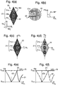
- each of the at least three regions of the first group exhibits a maximum rate of change in the degree of obstruction with tilt angle when the device is tilted relative to the viewer about different respective tilt axes, whereby as the tilt direction is changed relative to the viewer, a different one of the at least three regions of the first group exhibits its maximum or minimum degree of obstruction in turn.
- the at least three regions will display different behaviour, and as the tilted device is rotated (i.e. the tilt direction / tilt axis is progressively changed), different ones of the regions will become optimised to exhibit maximum rate of variation.
- the tilt axes about which each respective region of the first group exhibits its maximum rate of change in degree of obstruction with tilt angle lie at angles which successively increase relative to a reference direction from one region to the next region of the first group in series, whereby as the tilt direction is changed relative to the viewer, regions of the first group exhibit maximum or minimum obstruction in sequence along a continuous direction.
- the darkest or lightest area of the device appears to move in an identifiable direction (e.g. along a straight or curved line, or towards the interior or exterior of the device), when viewed from an off-axis location.
- the regions of the first group are adjacent one another such that the movement appears to take place smoothly from one region to the immediately adjacent region.
- this is not essential and the regions of the group could be spaced, e.g. by other regions of the device as discussed below.
- the at least three regions of the first group exhibit substantially no contrast between them when the device is viewed from the normal position. That is, each of the regions displays substantially the same obstruction level to a viewer positioned on the device normal. In this way, the boundaries between the regions are not distinguishable to the naked eye when viewed from the normal, such that any information defined by the regions is hidden but will be revealed when the device is tilted.
- the amount of lateral offset between the first and second patterns is the same in each of the at least three regions of the first group.
- the lateral offset between the first and second patterns is such that the elements of the first pattern are complementary to those of the second pattern, being located in between the elements of the second pattern, whereby from the normal viewing position, the at least three regions of the first group each exhibit their maximum degree of obstruction. Thus, the three regions may all appear dark when viewed from the normal.
- the lateral offset between the first and second patterns is such that the elements of the first pattern are non-complementary to those of the second pattern, being located directly in line with the elements of the second pattern, whereby from the normal viewing position, the at least three regions of the first group each exhibit their minimum degree of obstruction. In this case, the three regions may all appear light when viewed from the normal.
- the regions could have some intermediate offset value (i.e. in-between complementary and non-complementary), in which case when viewed from the normal each would exhibit an intermediate level of obstruction.
- the tilt axis about which the region exhibits a maximum rate of change in the degree of obstruction exhibited with tilt angle is determined by a pattern direction of the region, lying in the plane of the device, which pattern direction is defined by the first and second patterns in combination, arising from anisotropy of the first and/or second pattern or from the lateral positioning of the elements of the first pattern relative to the elements of the second pattern, the pattern direction of each region of the first group being different.
- a pattern direction can be attributed to any pair of first and second patterns based either on directional features in one or both patterns, or on the relative positioning of the two.
- the angular difference in pattern direction between one region and another in the first group determines how "quickly" the area showing the maximum obstruction level will appear to move from one region to another as the device is rotated: the greater the angular difference, the more rotation is required before the region exhibiting maximum obstruction will appear to change and hence the slower the motion effect (although the large step-change between regions may result in a "flashy” or sudden dynamic effect). If the angular difference is small, successive regions in the series may display similar behaviour to one another making them less distinguishable from one another. This may be beneficial in certain implementations but generally a greater visual distinction between regions is preferred into order to define the dynamic effect more clearly. It has been found particularly effective if the respective pattern directions of the at least three regions of the first group form a set of pattern directions which are angularly spaced from one another by between 5 and 45 degrees, preferably between 15 and 40 degrees, more preferably around 30 degrees.
- the respective pattern directions of the at least three regions of the first group form a set of pattern directions which are angularly spaced from one another by substantially the same amount between each angularly adjacent pair of pattern directions. This causes the apparent motion effect to move between regions at a substantially constant rate as the device is rotated. In other cases, the amount of change in pattern direction between sequential regions could be varied in different areas of the device to provide the illusion of acceleration and/or deceleration.
- each respective pattern direction of the at least three regions of the first group makes an angle with a reference direction which successively increases from one region to the next region of the first group in series, preferably by a substantially constant increment, whereby as the tilt direction is changed relative to the viewer (i.e. the tilted device is rotated), regions of the first group exhibit maximum or minimum obstruction in sequence along a continuous direction, the regions of the first group preferably being adjacent one another.
- the motion appears to move in a continuous direction and preferably at a continuous rate.
- the at least three regions could be configured to display their maximum rate of obstruction variation when tilted about tilt axes which lie within less than 90 degrees of each other, e.g. between 30 and 60 degrees of each other.
- the at least three regions of the first group include a first region and a second region, the tilt axes about which the first and second regions respectively exhibit their maximum rate of change in degree of obstruction with tilt angle lying at approximately 90 degrees to one another. In this way whichever direction the device is tilted in, at least the first or the second region (or both) will display a variation in obstruction level and the device will not appear static.
- both the maximum and minimum levels of obstruction will be visible in different regions of the device.
- at least one, preferably a plurality, of the at least three regions of the first group is located between the first and second regions. Since these in-between regions will operate best (fastest) on different tilt axes from the orthogonal axes for which the first and second regions are optimised, they will provide intermediate obstruction levels.
- the change in pattern direction between the first and second regions is spread evenly across the in-between regions. That is, preferably, the first group comprises N regions, of which (N-2) regions are located between the first and second regions, the respective tilt axes about which each of the N regions exhibits its maximum rate of change in obstruction with tilt angle being angularly separated from one another by approximately 90/(N-1) degrees.
- the in-between regions could be in any order, but preferably, the angle of the respective tilt axes about which each of the N regions of the first group exhibits its maximum rate of change in obstruction with tilt angle, relative to that of the first region, increases from each region to the next region of the first group towards the second region.
- the movement will appear to move in a continuous manner from one region to the next, and the device will have a graduated appearance when viewed away from the normal.
- the second primary mechanism for obtaining the described dynamic visual effect is to vary the lateral offset between the two patterns from one region to another.
- the lateral offset of the first pattern relative to the second pattern is different in each of the at least three regions of the first group, whereby when viewed from the normal viewing position, contrast is exhibited between each of the regions of the first group and when the tilt angle is changed relative to the viewer along at least one tilt direction, the contrast exhibited between each of the regions of the first group changes.
- the at least one tilt direction which reveals the change in contrast may be parallel to the direction of lateral offset, but this is not essential depending on the patterns in question.
- the at least one tilt direction which reveals the change in contrast is preferably the tilt direction along which the patterns exhibit fastest change in obstruction level, as discussed above - e.g. perpendicular to the elongate direction of a line pattern.
- the change in contrast may take any form but typically, as the device is tilted in the at least one direction, different ones of the regions will exhibit their maximum or minimum obstruction level, one after the other.
- at different tilt angles along the at least one tilt direction different ones of the at least three regions of the first group exhibit maximum obstruction.
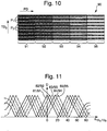
- the lateral offset between the first and second patterns in a constant offset direction increases successively from one region to the next region of the first group, preferably by a substantially constant increment, whereby, at any viewing position, in combination the regions of the first group exhibit a spatially graduated degree of obstruction across the device and as the tilt angle is changed along the at least one tilt direction, regions of the first group in series along a continuous direction exhibit maximum obstruction in sequence. This produces a particularly strong visual effect since the eye is led in a continuous direction by the apparent movement.
- the regions of the first group are adjacent one another so that the movement appears smooth. However this is not essential and the regions could be spaced (e.g. by 1cm or less), optionally by other regions of the device.
- the lateral offset between the first and second patterns increases from one region of the first group to another, preferably the next region of the first group in series, by an amount less than Q/4, where Q is the pitch of the pattern in the lateral offset direction, preferably less than or equal to Q/6, more preferably less than or equal to Q/8.
- these shift amounts are based on the assumption that the shift is in the direction parallel to the tilt direction in which the patterns exhibit the fastest change in obstruction level (e.g. the direction perpendicular to the elongate direction of a line pattern). If the shift takes place in another direction, the component of the shift in this direction parallel to the tilt direction in which the patterns exhibit the fastest change in obstruction level is key and preferably takes the values mentioned above.
- the at least three regions of the first group include a first region and a second region, the first region having a lateral offset of approximately zero, whereby the first and second patterns are non-complementary, and the second region having a lateral offset of Q/2, where Q is the pitch of the pattern in the lateral offset direction, and at least one, preferably a plurality, of the at least three regions of the first group is located between the first and second regions.
- the first and second patterns are complementary to one another.
- the first region will exhibit its minimum level of obstruction and the second its maximum, with the in-between region(s) displaying intermediate obstruction level(s). This ensures that the maximum degree of contrast can be seen in the device.
- the difference in the lateral offset between sequential regions is approximately equal.
- the first group comprises N regions, of which (N-2) regions are located between the first and second regions, and the respective lateral offsets for each of the N regions differ from one another by approximately Q/(2(N-1)).
- the respective lateral offset for each of the N regions, relative to that of the first region increases from each region to the next region of the first group in series towards the second region.
- the variation in lateral offset can be implemented in various ways.
- the elements in the second and third regions of the first group are laterally shifted relative to those in the first region to provide the change in lateral offset between regions. That is, the elements of one pattern have a constant periodicity and spacing across the first, second and third regions whilst the other pattern incorporates shifts at the region boundaries.
- the elements in the second and third regions of the first group are laterally shifted relative to those in the first region to provide the change in lateral offset between regions, the lateral shift of the elements in the first pattern being opposite in direction to the lateral shift of the elements in the second pattern. That is, the offset variation is "shared" between the two patterns.
- the amount of offset shift may be equal or different in the two patterns.
- At least a pair of the at least three regions of the first group have a lateral offset (relative to that in the first region) substantially equal in magnitude but opposite in direction, whereby when the device is viewed from the normal position, the pair of regions exhibits substantially equal degrees of obstruction whilst when the device is tilted relative to the viewer along the tilt direction parallel to the offset direction, one of the pair of regions exhibits an increased degree of obstruction whilst the other of the pair of regions exhibits a reduced degree of obstruction.
- a dynamic effect between the regions can also be achieved by varying the pattern direction between regions.
- the pattern direction is not varied between regions.
- a pattern direction, lying in the plane of the device is defined in each region by the first and second patterns in combination, arising from anisotropy of the first and/or second pattern or from the lateral positioning of the elements of the first pattern relative to the elements of the second pattern, the pattern direction of each of the at least three regions of the first group preferably being parallel.
- the device further comprises a fourth region in which the pattern direction makes a non-zero angle, preferably approximately 90 degrees, with that of the at least three regions of the first group, whereby as the device is tilted in the tilt direction parallel to the offset direction, the fourth region exhibits a lower rate of change in the degree of obstruction with tilt angle than the at least three regions of the first group, preferably substantially no change.
- the fourth region exhibits a different behaviour to that of the first group, drawing a clear contrast between it and the first group.
- the fourth region could be configured to define information (e.g. be provided in the shape of a number, letter, symbol or graphic), with the first group of regions acting as a dynamic background, or vice versa.
- the device may comprise one or more further regions in addition to those of the first group.
- the first and second patterns of elements are further configured so as to define a second group of regions comprising at least two (preferably at least three) further regions of the device, each region of the second group exhibiting a maximum degree of obstruction when observed by a viewer from at least one maxima viewing position, and a minimum degree of obstruction when observed by a viewer from at least one minima viewing position, the at least one maxima viewing position and the at least one minima viewing position constituting a set of peak viewing positions for each region, and wherein the sets of peak viewing positions associated with each of the regions of the second group respectively are different from one another, the first and second patterns being configured such that, as the viewing position is changed, the second group of regions displays a change in obstruction levels which is different from that exhibited by the first group of regions.
- the second group of regions could be implemented using any of the techniques described above for the first group.
- the second group could comprise regions of different pattern direction or of varying lateral offset.
- the chosen technique may be different for the first and second groups.
- the second group may alternatively be "static", without any dynamic variation between regions, if desired. Any number of groups of regions could be provided.
- the first and second patterns are configured such that, as the viewing position is changed, a respective maxima viewing position or a respective minima viewing position for each of the at least two regions of the second group of regions is reached in the same order as that in which the corresponding regions are arranged spatially across the device in a second continuous direction, different from the first continuous direction. This produces a strong visual impact which is extremely difficult to mimic using other means.
- the various groups of regions could be isolated from one another or arranged adjacent one another in the device. However, it is advantageous if the regions of the first and second groups are interleaved with one another across the device. This increases the complexity and hence the security level of the device, and can also be used to improve the overall visual effect.
- the lateral offset of the first pattern relative to the second pattern is different in each of the at least two regions of the second group, whereby when viewed from the normal viewing position, contrast is exhibited between each of the regions of the second group and when the tilt angle is changed relative to the viewer along at least a tilt direction, the contrast exhibited between each of the regions of the second group changes, wherein the offset direction within the first group is not parallel to that within the second group.
- the two groups of regions are optimised to exhibit a dynamic visual effect when the device is tilted in different directions. This assists in ensuring that, whichever direction the device is tilted in, at least some of the regions will exhibit the desired dynamic effect.
- regions are provided, preferably either the pattern direction defined by the first and second patterns in combination or the lateral offset between the first and second patterns, or both, varies from one region of the device to another. Nonetheless, more than one of the regions could share the same offset amount and pattern direction and hence display the same appearance as the device is tilted.
- the regions of the device could be arranged with any desired positioning relative to one another. However, it is preferred that at least some of the regions abut one another or are spaced from one another by no more than 1 cm, preferably no more than 0.5 cm. This assists the viewer in perceiving the changes in contrast between the regions as the device is tilted and/or rotated.
- the device could take any configuration but in preferred examples the regions may be arranged to emphasise or to relate to the dynamic effect perceived upon tilting and/or rotating.
- the regions of the device are arranged along a line, preferably a rectilinear line.
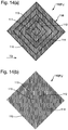
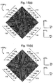
- the regions of the device are concentric, preferably circles, squares, rectangles, triangles or any other shape.
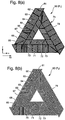
- the regions of the device are arranged to form one or more symbols, letters, numbers, pictorial graphics or spirals, preferably a circular, triangular or square spiral.
- the size or weight (e.g. line width) of the pattern elements will be constant across the device. However, this can be varied to introduce an additional visual effect to the device.
- the size or weight of the elements making up the first and/or second patterns is varied across the device in accordance with a third pattern which appears superimposed on the device, locations of relatively high element size or weight exhibiting a relatively high degree of obstruction compared with their surroundings at all viewing positions, and locations of relatively low element size or weight exhibiting a relatively low degree of obstruction compared with their surroundings at all viewing positions.
- one or both of the patterns could take the form of a screened working, with the variation in element size or weight imparting a variation in tone which can be used to convey information such as alphanumerical text, a letter, digit, symbol or graphic.
- the resulting image will remain static as the device is tilted and/or rotated, with the dynamic effect already described appearing as a background to the image.
- the image may or may not be related to the shape or position of the various regions making up the device.
- each of the first and second patterns is periodic and has equal periodicity.
- the periodicity of the patterns could vary from one region to another and this may be utilised to vary the apparent "speed" of the dynamic effect as the device is tilted or rotated.
- the first and second patterns could take many different forms but preferably are adapted to approximately tessellate with one another. That is, it should preferably be possible to move the two patterns relative to one another (theoretically, not in practice) such that the pattern elements of one "fill in" the gaps (or secondary pattern elements) of the other more or less precisely. However, it is not essential that this tessellation be exact.
- the first and/or second patterns may comprise any of:
- dot elements need not be circular but could take any shape, including indicia such as a number, letter or other symbol.
- Line or dot elements could also contain negative indicia such as letters or numbers defined by a gap inside an element, and similarly line or dot elements could be made up by a plurality of positive indicia, joined up or not.
- the elements of the first and/or second patterns may be spaced from other elements within the same pattern by gaps (i.e. the absence of pattern elements) or by contrasting elements ("secondary pattern elements").
- the surface area proportion of elements to intervening gaps or contrasting elements is between 30 and 70 %, preferably between 40 and 60 %, more preferably approximately 50%.
- this could be varied across the device, optionally in accordance with a third pattern, e.g. to define information.
- a third pattern e.g. to define information.
- the proportion of elements to intervening gaps or contrasting elements can give rise to different effects. For instance, a higher line weight (e.g.
- the aspect ratio of the pattern dimensions to the distance between the two patterns (set by the transparent layer) also affects the rate of change in obstruction level with tilt angle, and hence the angles to which the device must be tilted in order to perceive the described changes in appearance.
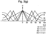
- the smaller the ratio of the pattern pitch of the first and/or second pattern to the thickness of the transparent layer the faster the rate of change, hence the lower the required tilt angles will be and the more readily the effects will be obtained.
- the smallest values of pitch:thickness ratio (“Q:d" ratio) that are achievable with available pattern forming techniques will generally be preferred.
- the present inventors have found it most advantageous if the ratio is between 1.5:1 and 3:1, preferably between 1.67:1 and 2.33:1, more preferably around 2:1.
- the minimum size of the pattern elements may be restricted by the technique by which the pattern is formed.
- the size is preferably kept small in order to improve the ratio mentioned above and also in order that the individual elements are not overly conspicuous to the observer.
- the elements of the first and/or second pattern have a minimum dimension (e.g. linewidth, L) in the range 50 to 150 microns, preferably around 100 microns.
- the first and/or second pattern has a pitch Q in the range 100 to 300 microns, preferably around 200 microns.
- each region could have any size and shape appropriate for the chosen device configuration. There is no maximum size limitation on the size of each region. Preferably, each region has a minimum dimension of at least 1 times the pitch of the first and/or second pattern. That is, each region will contain at least one pattern repeat at the required pattern direction and/or offset. If there is a single pattern repeat in each region, and the regions are arranged in series order as described above, the dynamic effect will appear substantially continuous with no clear divide between one region and the next. As the size of the regions increases relative to the pattern repeat, the dynamic effect becomes increasing "step wise", with discrete regions each exhibiting a uniform appearance at each viewing position, which can be distinguished from the next region. Both implementation techniques can be used to good effect.
- the elements of the first and/or second patterns are substantially opaque such that an increase in the degree of obstruction exhibited by a region appears as an increase in darkness of the region.
- the elements of the first and/or second patterns are coloured and/or semi-transparent such that a change in the degree of obstruction exhibited by a region appears as a change of the colour of the region, in terms of its hue, tone, opacity and/or brightness.
- the elements of the first pattern may have a first colour and the elements of the second pattern may have a second, different colour.
- the two colour will be "mixed" by the eye to differing extents, thereby appearing as different shades.
- the two patterns can be formed using any desired techniques.
- the first and/or second pattern is printed (e.g. by offset, lithographic or gravure printing), metallised, exposed via a mask (e.g. photosensitive material), or laser-marked, preferably onto or into the transparent layer.
- a mask e.g. photosensitive material
- laser-marked preferably onto or into the transparent layer.
- photopatterning techniques such as those disclosed in our British Patent Application No. 1117523.9 may advantageously be used.
- the pattern elements could comprise a single layer of material or be formed of multiple, registered layers. For example, if the elements are metallic and created by patterning of metallised areas than each pattern element may comprise a layer of resist material and a layer of metal.
- the pattern element may have different appearances from one another (e.g. different colours).
- the outermost layer of the pattern element facing away from the transparent layer
- the innermost layer facing towards the transparent layer
- another colour e.g. red
- This "inner” colour layer may be hidden at certain viewing angles and revealed to a greater or lesser extent as the device is tilted. If the "inner" colour is different for the first and second patterns, the device will also present a different colour appearance depending on from which side it is viewed, in addition to the colour variation upon tilt. The colours could also vary from one region of the device to another.
- the security device could be designed for viewing in transmission, with all layers of the device being at least semi-transparent (apart from the material forming the pattern elements, which may be opaque).
- the device preferably further comprises a reflective surface located such that one of the first pattern and the second pattern is positioned between the reflective surface and the transparent layer whereby when the device is viewed from the side having the other of the first pattern and the second pattern, both patterns can be observed against the reflective surface.
- the two patterns could be arranged according to any of the options discussed above.
- the resulting optical effect may not be identical to that obtained in a transmissive version of the device with the same two patterns. This is due to the presence of an additional pattern in the form of the reflected image of whichever of the first and second patterns is spaced from the reflective surface.
- the first and second patterns have a lateral offset which varies from one region to the next in the manner discussed above
- the visual effect of the offset will be combined with an additional obstruction variation as the device is tilted due to the interaction of one or both of the patterns with their reflections. This can be used to generate particularly complex visual effects which are very difficult to imitate.
- the pattern(s) spaced from the reflective surface is/are formed of multiple layers of different colour, as described above, the reflected image pattern(s) may have a different colour to that of the originals, introducing further levels of complexity to the effect.
- the elements of the first and/or second pattern could comprise a security substance such as luminescent material, fluorescent material, thermochromic material, UV responsive material, magnetic material, birefringent material or polarising material.
- a security substance such as luminescent material, fluorescent material, thermochromic material, UV responsive material, magnetic material, birefringent material or polarising material.
- such material could be included in any one or more layers of a multilayer pattern element.
- the transparent layer could comprise a coloured tint and/or a security substance such as luminescent material, fluorescent material, thermochromic material, UV responsive material, birefringent material or polarising material.
- the device could further comprise a decorative layer carrying a fourth pattern, preferably a printed decorative layer.
- a decorative layer carrying a fourth pattern preferably a printed decorative layer. This could be used, for example, to define the outline of an image, with the above described dynamic effect "filling in” the image or providing a background thereto.
- the first and/or second patterns could also include a border (typically referred to as a "hairline") outlining each of the at least three regions and delimiting it from the next.
- a border typically referred to as a "hairline”
- the inclusion of such a hairline results in a stronger visual distinction between each region whilst omitting the hairline produces a "smoother" effect. Either approach may be preferred depending on the design of the device.
- a security device comprising a first pattern of elements and a reflective surface spaced by a transparent layer, the first patterns of elements obstructing the passage of light reflected to a viewer by the device to a varying degree depending on the viewing position, wherein the first pattern of elements is configured to define at least two regions of the device, of which a first region exhibits a maximum rate of change in the degree of obstruction with tilt angle when the device is tilted relative to the viewer about a second tilt axis which is not parallel to the first tilt axis.
- the second pattern is a "virtual" pattern formed as a reflection of the first pattern.
- the observer perceives a combination of the first pattern and its reflection formed by the reflective surface.
- the positions of the first pattern and its reflection will appear to move relative to one another in the same way as described previously, due to the spacing resulting from the transparent layer.
- the first pattern and its reflected image co-operate to obstruct light being reflected by the device to a varying degree which depends on the viewing angle.
- the first pattern will appear to have the spaces between its pattern elements "filled” by those of the reflected, virtual pattern, thereby exhibiting the maximum obstruction level, whilst at other viewing angles, the real and virtual pattern elements will overlap to a greater or lesser extent, resulting in lower obstructions levels.
- the term "obstruction" here has the same meaning as discussed in relation to the first and second aspects of the invention and the elements of the first pattern are generally of higher optical density than the transparent layer, e.g. coloured and/or opaque.
- the change in perceived obstruction level may appear as a change in the darkness of the device, or could appear as a change in colour or colour density.
- the device By forming the device in this way, using a reflective surface, the previously described "switching" or dynamic visual effects of the first and second aspects of the invention respectively, can be viewed under reflected light. This is useful since the device can then be incorporated into or applied to any object and there is no requirement for a transparent or translucent portion of the object to be aligned with the device in order to permit the transmission of light therethrough.
- the device could be manufactured into a security thread which is incorporated into a banknote in a conventional manner with portions of the thread being revealed through windows on one side of the note only, or the device could be included in a sticker-type article for application to any object.
- a further advantage of this aspect is that the required thickness of the transparent layer for any particular ratio of pitch-to-spacing between the patterns (Q:d) is less than that required in corresponding implementations of the previous aspects of the invention.
- the reflected, "virtual" pattern appears to the viewer to be located a distance behind the reflective surface: the effective thickness of the transparent layer is doubled, meaning that a transparent layer of half the thickness utilised in previous embodiments can be employed to achieve the same visual result.
- the thickness of the transparent layer can be maintained, in which case the visual effect will be enhanced (particularly, changes in obstruction level will be apparent at smaller tilt angles) as compared with implementations of the previous aspects since the (Q:d) ratio will effectively be reduced.
- Implementations according to said aspect can be utilised to form security devices exhibiting many of the effects already described with respect to the first aspect of the invention.
- the second region of the device when the device is tilted about the first tilt axis, the second region of the device exhibits substantially no change in the degree of obstruction.
- the first and second tilt axes are substantially perpendicular to one another.
- the first and second regions exhibit substantially no contrast between them when the device is viewed from the normal position.
- the tilt axis about which the region exhibits a maximum rate of change in the degree of obstruction exhibited with tilt angle is determined by a pattern direction of the region, lying in the plane of the device, which pattern direction is defined by anisotropy of the pattern of elements, the pattern direction of the first region being non-parallel to that of the second region.
- the pattern direction of the first region makes an angle of between 5 and 90 degrees with that of the second region, preferably between 45 and 90 degrees, more preferably between 75 and 90 degrees.
- Implementations according to said aspect can also be utilised to form security devices exhibiting many of the effects already described with respect to the second aspect of the invention.
- the virtual pattern is a reflection of the first pattern, if no further pattern is provided, it is not possible to laterally offset the two patterns relative to one another.
- the virtual pattern elements will in all cases be precisely occluded by the "real" pattern elements of the first pattern (i.e. fully non-complementary). Nonetheless, dynamic visual effects utilising different tilt directions can still be obtained.
- At least three regions of the device are defined, constituting a first group of regions, each of the at least three regions of the first group exhibiting a maximum rate of change in the degree of obstruction with tilt angle when the device is tilted relative to the viewer about different respective tilt axes, whereby as the tilt direction is changed relative to the viewer, a different one of the at least three regions of the first group exhibits its maximum degree of obstruction in turn.
- more than one group of regions may be provided, preferably exhibiting different behaviour.
- the pattern is configured such that, as the viewing position is changed, a respective maxima viewing position or a respective minima viewing position for each of the at least three regions of the first group is reached in the same order as that in which the corresponding regions are arranged spatially across the device in a first continuous direction.
- the tilt axes about which each respective region exhibits its maximum rate of change in degree of obstruction with tilt angle lie at angles which successively increase relative to a reference direction from one region to the next adjacent region in series, whereby as the tilt direction is changed relative to the viewer, adjacent regions exhibit their maximum or minimum obstruction in sequence.
- the tilt axes which produce the greatest (fastest) variation for each region are typically defined by the pattern direction in each region and preferably, the respective pattern directions of the at least three regions of the first group form a set of pattern directions which are angularly spaced from one another by between 5 and 45 degrees, preferably between 7 and 25 degrees, more preferably around 15 degrees.
- the respective pattern directions of the at least three regions of the first group form a set of pattern directions which are angularly spaced from one another by substantially the same amount between each angularly adjacent pair of pattern directions.
- each respective pattern direction of the at least three regions of the first group makes an angle with a reference direction which successively increases from one region to the next adjacent region in series, preferably by a substantially constant increment, whereby as the tilt direction is changed relative to the viewer, adjacent regions exhibit their maximum or minimum obstruction in sequence.
- At least one, preferably a plurality, of the at least three regions of the first group is located between the first and second regions.
- the first group comprises N regions, of which (N-2) regions are located between the first and second regions, preferably the respective tilt axes about which each of the N regions exhibits its maximum change in obstruction are angularly separated from one another by approximately 90/(N-1) degrees.
- the angle of the respective tilt axes about which each of the N regions of the first group exhibits its maximum rate of change in obstruction with tilt angle, relative to that of the first region increases from each region to the next region of the first group towards the second region.
- the device further comprises a second pattern of elements located between the reflective surface and the transparent layer, the second pattern of elements preferably being disposed in or on the reflective surface.
- the second pattern of elements can be used to implement a variation in offset in addition to the variation in pattern direction discussed above.
- the lateral offset of the first pattern relative to the second pattern is different in at least some of the at least two regions, whereby when viewed from the normal viewing position, contrast is exhibited between the regions and when the tilt angle is changed relative to the viewer along at least one tilt direction, the contrast exhibited between the regions changes.
- the change in lateral offset could be between every region, or sets of plural regions could share the same offset level.
- the resulting visual effect comprises a graduating change in contrast across the device which moves as the device is tilted, but on which is superimposed a further variation between dark and bright in each region.
- Particularly complex visual effects can thus be designed which are extremely difficult to imitate.
- the pattern elements could be formed of a single layer, or could be multi-layered, and if so those (registered) layers could have different colours.
- This latter implementation is particularly advantageous in the third aspect of the invention since if the outermost and innermost layers of the pattern elements are of different appearance (e.g. colour), the appearance of the pattern elements in the virtual "second" pattern (i.e. the reflection of the first pattern) will be different from that of the first pattern. This may give the impression of each region varying from colourless when the device is viewed from the normal (since the reflected image of the first pattern will be directly concealed under the first pattern itself), to taking on the "hidden" colour as the device is tilted away from the normal.
- the outermost and innermost layers of the pattern elements are of different appearance (e.g. colour)
- the appearance of the pattern elements in the virtual "second" pattern i.e. the reflection of the first pattern
- This may give the impression of each region varying from colourless when the device is viewed from the normal (since the reflected image of
- the regions will display the variation at different rates for any one tilt direction, as the device is tilted, one region will display the colour before the other, thereby presenting a strong contrast between the regions. If the pattern elements in different regions are formed with innermost layers of different colour from one region to the other, this distinction will again be revealed upon tilting, producing a strong contrast effect.
- the first pattern could comprise line elements, dot elements or any of the other options discussed above in relation to the first and second aspects of the invention.
- the transparent layer may comprise a coloured tint and/or a security substance such as luminescent material, fluorescent material, thermochromic material, UV responsive material, machine readable material, birefringent material, polarising material or transparent magnetic material.
- the pattern of elements could be formed using any of the techniques, e.g. printing, metallisation, etc. previously discussed.
- Multi-layer pattern element structures may be formed for example by applying two or more layers in register with one another, e.g. by applying a coloured resist to a metal layer and performing etching to remove the areas not covered by resist, such that pattern elements having metal and resist layers remain.
- a further decorative layer carrying a fourth pattern, preferably a printed decorative layer, could be incorporated if desired.
- the reflective surface is preferably specularly reflective in order to produce a sharp image of the pattern of elements. Any material giving rise to a reflection of the pattern of elements could be used to form the reflective surface, but advantageously, the reflective surface comprises a reflective layer adjacent the transparent layer, preferably comprising metallic material, a thin film structure or a material of different refractive index from the transparent layer. For instance, a high refractive index material could be used if it is desired that the device as a whole be see-through.
- security devices of the sorts described above comprising two patterns of elements can be, depending on the design of the device, tolerant to a reasonably large amount of mis-registration between the two patterns. This can be beneficial in the sense that manufacturing of the devices is simplified. However, for the same reason, the risk of a successful counterfeit device being produced is increased.
- a security device comprising a first pattern of elements and a second, overlapping, pattern of elements spaced by a transparent layer, the first and second patterns in combination obstructing the passage of light transmitted to a viewer through the device to a varying degree depending on the viewing position, the first pattern of elements defining therewithin a first cut-out zone in which no pattern elements are present, and the second pattern of elements defining therewithin a second cut-out zone in which no pattern elements are present, at least a portion of the first cut-out zone being of being of the same shape and size as at least a portion of the second cut-out zone and the first and second cut-out zones being registered to one another such that, at least when viewed from the normal, light is transmitted to the viewer through at least the portion of the two cut-out zones.
- cut-out zones could be usefully applied to any security device in which high registration between two line patterns is not essential to achieve the primary visual effect.
- examples of such devices include moire interference devices and other devices disclosed in our British patent application no. 1117523.9 , as well as those of the invention.
- each pattern By providing each pattern with a cut-out zone (or portion thereof) of the same shape and size and registering the two to one another, the difficulty of manufacturing a successful device is increased and hence the security of the device is enhanced. If the matching portions of the cut-out zones are correctly registered, the alignment of the two zones will result in a zone through which light can be transmitted without obstruction by any pattern elements, thereby appearing bright relative to the rest of the device. If however sufficient registration is not achieved (e.g. in a counterfeit device), the visibility of the cut-out zones will be reduced (or, preferably the cut-out zones will no longer be visible) since the zone in the first pattern will overlap a portion of the second pattern, and vice versa, at least to some extent. Viewing of the cut-out zones will therefore be obstructed by the overlapping patterns and the features will not appear as expected or may disappear entirely. This provides a significant obstacle for a counterfeiter to overcome, and a straightforward test for a genuine document.
- each of the first and second cut-out zones has a minimum dimension in at least one direction which is less than or equal to 5mm, preferably less than or equal to 3mm, more preferably less than or equal to 1mm, still preferably less than or equal to 0.5 mm, most preferably less than or equal to 250 microns.
- a registration tolerance of around 200 microns can be achieved and hence a cut-out zone having a width of between 250 and 500 microns should be reproduced reliably.
- ink-jet printing apparatus as may be available to a would-be counterfeiter may only be able to achieve registration to around 500 microns and so reproduction of the same feature would be extremely difficult.
- cut-out zones it is not essential for the cut-out zones to have minimum dimensions on this scale since even larger cut-outs will reveal mis-registration since their appearance in transmitted light will noticeably change due to the encroachment of one of the patterns into the cut-out.
- each cut-out need match the other.
- one or both cut-outs could extend beyond the matching portion, e.g. as part of a design.
- the first and second cut-out zones could be surrounded by the first and second patterns respectively on all sides or in alternative preferred embodiments, the first and second cut-out zones each adjoins an edge of the respective first or second pattern.
- the matching portion of each cut-out zone takes the form of one or more lines with linewidth of the dimensions discussed above, the line(s) following at least two different directions in the plane of the device. In this way, mis-registration in any direction can be identified since the appearance of at least one of the line directions will be affected.
- the one or more lines could be continuous (e.g. including a corner or intersection, or being curved), or could be spaced from one another.
- the first and second cut-out zones each has the form of an item of information, or a part thereof, such as a letter, number or symbol, or a graphic or pattern, such as a guilloche or fine line pattern.
- the item of information is preferably formed with a linewidth which is less than or equal to 5mm, preferably less than or equal to 3mm, more preferably less than or equal to 1mm, still preferably less than or equal to 0.5 mm, most preferably less than or equal to 250 microns, such that any misregistration will change the appearance of the item of information or cause it to disappear.
- one or both of the cut-out zones is provided with a visible outline. This assists in clearly defining the feature, particularly if only a part an the item of information is defined by the cut-out zones, since the remainder of the item can be delimited by the outline, rendering the feature more easily recognisable and drawing attention to the requirement for the cut-out to be present.
- the visual effect to which the two patterns of elements give rise could be based on any known mechanism.
- the first and second patterns in combination provide a venetian blind effect, a moire interference pattern, an animation effect created using a barrier strip method as described in WO2011007344 or an optically variable effect viewable in transmitted light generated by the combination of modified line structures for example as described in WO2011076361 .
- the two patterns are arranged to exhibit effects of the sorts discussed with respect to the invention and hence the security device may additionally comprise any of the features discussed above.
- the invention further provides a security article comprising a security device according to any of the aspects discussed above, wherein the security article is preferably a security thread, strip, patch, label or transfer foil.
- the invention further provides a security document comprising a security article as described above, wherein the security article is preferably located in a transparent window region of the document, or is inserted as a window thread, or is affixed to a surface of the document.
- the present invention further provides a security document comprising a security device according to any of the described aspects, the security document comprising a transparent substrate forming the transparent layer of the security device.
- the security document may include a transparent layer as an integral part thereof, to which the above-described patterns of elements are applied (or one pattern and a reflective surface) to form the security device.
- the security document is any of: currency (e.g. a banknote, particularly a polymer (plastic) banknote), an identification document, an identification card, a passport, a licence, a certificate of authenticity, a cheque, a stamp or any other document of value.
- Figure 1 shows an exemplary security device 10 disposed on a layer 1 which sits in an approximately planar surface defined by X and Y orthogonal axes.
- the third orthogonal Z axis is normal to the plane of the device, and as such an observer viewing the device 10 from any position along the Z axis has a normal viewing position.
- An observer O 1 at an arbitrary viewing position (VP) away from the normal is shown in Figure 1 .
- the viewing position VP is defined by the tilt angle ⁇ between the viewing position VP and the normal (Z axis) in combination with either the tilt direction (TD) or the tilt axis (TA).
- the tilt direction TD is the intersection of the plane through which the tilting occurs with the plane of the device, whilst the tilt axis TA is the axis about which tilting occurs.
- the tilt direction TD will be perpendicular to the tilt axis TA, both lying in the plane of the device.
- the tilt direction TD and tilt axis TA can be defined in terms of their Cartesian coordinates in the X, Y plane, but for convenience may be referred to in terms of the cylindrical angle ⁇ between the respective direction and the X axis, as shown in Figure 1 .
- Rotating the device about the Z axis will change the value of ⁇ such that observer O 1 depicted in Figure 1 will see the device from a series of viewing positions on the surface of the chain-dashed cone shown in the Figure.
- tilt means that there is a change in the tilt angle, ⁇
- tilt means that there is a change in angle ⁇
- rotating means that there is a change in angle ⁇ .
- a change in viewing position may involve either tilting or rotation or both.
- FIG. 2 shows a device 10 which comprises a transparent layer 1, which may optionally comprise a multilayered structure, formed for example of one or more substantially optically transparent polymers such as polypropylene, polyethylene teraphthalate (PET), polyethylene, polyamide, polycarbonate, polymethylmethacrylate (PMMA), or polyethylene naphthalate (PEN), provided with first and second patterns P 1 and P 2 on opposite sides of the layer 1.
- the patterns P 1 and P 2 are depicted as being formed on the surfaces of the layer 1 but in practice could be carried on separate sheets either side of the transparent layer.
- the transparent layer 1 may be formed as an air gap, with no material present.
- the patterns P 1 and P 2 may be formed using any available processes, including printing, preferably lithographic, gravure, or offset printing, metallization or laser marking for example, and may each be single-layered or multi-layered. Alternatively, one or both patterns could be formed by exposure through a mask, e.g. of photosensitive material.
- Each pattern P 1 and P 2 is formed of pattern elements 11, 13 which may be spaced by gaps 12, 14 as shown in Figure 2(a) or by secondary pattern elements having a different appearance from the primary pattern elements 11, 13 (e.g. a different color).
- the pattern elements 11 may be semi-transparent (e.g. having a colored tint) but in most preferred examples are of high optical density (i.e. higher than that of the transparent layer 1) and are preferably substantially opaque.
- the pattern elements may be printed in a dark color of ink, such as black or dark green.
- black or dark green e.g., black or dark green.
- the pattern elements may be printed in a dark color of ink, such as black or dark green.
- those layers may have different appearances (e.g. colours).
- the first and second patterns P 1 and P 2 at least partially overlap one another, although it should be noted that this refers to each pattern as a whole and not necessarily to the individual elements thereof.
- this refers to each pattern as a whole and not necessarily to the individual elements thereof.
- the elements 11 of pattern P 1 align with and precisely overlap each respective pattern element 13 of pattern P 2 , this will not be the case in all examples.
- the first and second patterns P 1 and P 2 are patterns of line elements 11, 13 of constant pitch (repeat length) Q and line width L, which here is substantially equal to the spacing or gap G between each line. It should be noted that it is not essential for the pitch Q or line width L to be constant across the whole device, but in any one locality, that of pattern P 1 should be approximately equal to that of pattern P 2 . The greater the line width L as a proportion of the pitch Q, the darker the device will appear. This may be varied across the device to impart a pattern or graphic on top of the effects to be described below, if desired.
- a pattern direction PD a lying parallel to the elongate axis of the line elements 11, 13 can be ascribed to the pattern.
- the direction of the pattern can be defined by any one or more features within the pattern which allow a direction to be defined relative to them.
- pattern direction PD b which is perpendicular to the elongate direction of the line elements.
- Figure 2(b) shows an alternative pattern of dot elements 15 arranged on a square grid.
- exemplary pattern directions PD a and PD b can be defined between selected dot elements as shown. It is not of consequence that, if rotated by 90 degrees, the defined pattern directions PD a and PD b could be mistaken for directions between other dot elements on the same grid (e.g. direction PD a ' shown in dashed lines), since due to the rotational symmetry of the pattern, the effects exhibited by the device will be identical.
- a pattern direction PD in cases where the first and second patterns P 1 and P 2 each individually are substantially anisotropic in the X-Y plane if the first and second patterns P 1 and P 2 are laterally offset from one another.
- the patterns P 1 and P 2 were to consist of sets of concentric circles, it may not be possible to identify a pattern direction PD in either pattern alone, since one orientation in the X-Y plane cannot be distinguished from another.
- the second pattern P 2 is offset laterally from the first P 1 in the direction indicated by line PD a , thereby defining a pattern direction.
- any other direction defined relative to this offset such as PD b , could be used instead.
- the pattern elements could take a wide range of forms including line elements and dot elements.
- dot elements could be arranged along lines to give the impression of line elements.
- Dot elements need not be circular but could take any shape, including indicia such as letters, numbers or other symbols.
- Line and/or dot elements could also have negative indicia defined as gaps within them, or could be made up of a plurality of positive indicia (joined up or not), acting for example as microtext in both implementations.
- Figure 3(a) shows a cross section of a device of much the same construction as that described above in relation to Figure 2(a) , although in this example the pattern elements 11 of the first pattern P 1 precisely do not align with the pattern elements 13 of the second pattern P 2 : i.e. the first and second patterns P 1 and P 2 are complementary to one another.
- the pitch of the two patterns Q 1 and Q 2 is substantially identical, as are the line widths L 1 and L 2 , and the spacing G 1 and G 2 .
- the pattern elements 11 of first pattern P 1 or those 13 of the second pattern P 2 will obstruct the passage of light through the device to the observer O 1 such that the device exhibits its maximum level of obstruction. That is, for example, where the pattern elements 11, 13 are substantially opaque, the device as a whole will appear dark. If the pattern elements 11, 13 are semi-transparent and coloured this may instead appear as the device exhibiting a particular colour. This will be discussed further below but, for ease of reference, the description will focus primarily on patterns of substantially opaque elements such that the level of obstruction corresponds to a level of darkness. It should be appreciated that wherever the "darkness level" is referred to below, this could instead be a particular colour or change in colour level.
- the viewing position is changed to increase the viewing angle (i.e. the device is tilted relative to the observer) the level of obstruction exhibited by the device will change.
- the viewing position changes from observer O 1 to observer O 2 (equivalent to tilting the device about tilt access TA 1 , which is parallel to the elongate direction of the line elements 11, 13), the apparent darkness of the device will decrease. This is best shown with respect to Figure 3(b) .
- the peaks e.g.
- the variation of transmission / obstruction level is not sinusoidal but tends towards a roughly triangular wave shape with an angular period ⁇ 1 , ⁇ 2 , ⁇ 3 ,... ⁇ n between adjacent peaks which decreases as the tilt angle increases.
- the exemplary device on which Figure 3(c) is based assumes that the material from which the transparent layer 1 is formed has a refractive index which is equal to that of its surroundings and hence does not take into account any refraction effects.
- the transparent layer 1 will have a different refractive index (commonly around 1.5) compared with its surroundings. This has a significant impact on the observed variation in obstruction level with tilt angle since, as shown in Figure 3(d) , the effective angle ⁇ ' at which light rays will travel between the patterns P 1 , P 2 through the transparent layer 1 will be smaller (i.e. closer to the normal) than the actual viewing angle ⁇ , due to Snell's law.
- Figure 3(e) is a plot of observed obstruction level (darkness, D) against (actual) tilt angle ⁇ in the direction TD 1 for a device of Q:d ratio 1:2, having a refractive index of 1.5.
- R the pitch-to-thickness ratio
- the rate of change of obstruction level with tilt angle is greater for lower vales of R.
- Figure 3(f) additionally shows the variation in obstruction level with tilt angle for a device with a Q:d ratio (R) of 2:0.7 (solid line), and a device with a Q:d ratio (R) of 2:1 (dashed line).
- a refractive index of around 1.5 has been assumed. It will be seen that the degree of obstruction changes with tilt angle ⁇ far more slowly than in the previous case, with not even a full half cycle being completed before the variation is curtailed by the critical angle.
- the ratio of the pattern pitch of the first and/or second pattern to the thickness of the transparent layer is between 1.5:1 and 3:1, preferably between 1.67:1 and 2.33:1, more preferably around 2:1.
- Typical layer thicknesses d will vary according to the manner in which the device is to be incorporated into or onto a product or a security document, for example, but typically may be of the order of 50 to 100 microns.
- the thickness may be between 50 and 100 microns.
- the thickness of the transparent layer may be lower, e.g. between 20 and 40 microns.
- the transparent layer thickness may be greater, e.g. up to 1mm.
- preferred line thicknesses L are also of a similar order of magnitude. For instance, where the thickness of the transparent layer d is around 75 microns, preferably the line thickness L is also around 75 microns (hence its pitch, Q, equaling approximately 150 microns). Devices with dimensions of this sort exhibit a clear change in appearance over viewing angles in the range 25 to 40 ⁇ 2 degrees, which is suitably small such that minimal tilting will be required in order to observe the desired effects.
- the device when the device is viewed at a range of angles along tilt direction TD 1 , which is perpendicular to the elongate direction of the line elements 11, 13, the device varies between a relatively dark and relatively light appearance in a manner dependent on its Q:d ratio and refractive index.
- the behaviour of the device will be different for a different tilt direction. For example, if the Figure 3(a) device were to be tilted in the perpendicular direction along the tilt direction TD 2 (parallel to the elongate direction of the line elements 11, 13), substantially no change in the level of obstruction exhibited would be observed. This is because the relative positions of the first and second patterns P 1 and P 2 will not change in a noticeable manner, with the respective pattern elements 11, 13 remaining in complementary positions to one another. As such, the device will continue to exhibit substantially its maximum darkness level.
- Figure 4 depicts an embodiment not forming part of the present invention which makes use of this phenomenon.
- Figure 4(a) shows the security device 20 when viewed from the normal position.
- the device 20 comprises two regions 21 and 22 of which the first region 21 comprises three sub-regions 21a, 21b and 21c having the shape of the digits 2, 0 and 0 respectively such that, together, the number "200" is conveyed.
- the boundary between the first region 21 and second region 22 is delineated with a light colored hairline, shown as dark line 23 in the enlarged detail of Figure 4(b) . However, in practice, this may be omitted.
- Each of the regions is provided with first and second patterns on either side of a transparent layer in the same manner as depicted in Figure 3(a) .
- the Q:d ratio of the device is around 1:2, and a refractive index of 1.5 is assumed.
- the pattern directions of the two regions are not parallel to one another.
- the line elements of both patterns P 1 and P 2 align with the X axis and the pattern direction PD 1 is defined in the same direction.
- the same pattern direction i.e. the direction parallel to the elongate elements
- PD 2 lies parallel to the Y axis.
- the pattern direction of the first region PD 1 makes an angle ⁇ with the pattern direction of the second region PD 2 , which in this example is 90 degrees.
- the two regions 21, 22 will behave differently from one another when the device is tilted.
- the maximum rate of change in the level of obstruction with tilt angle exhibited by each of the two respective regions will be obtained when the device is tilted in different, non-parallel tilt directions.
- Figure 4(c) depicts the device 20 when viewed away from the normal, having being tilted along the tilt direction TD 1 about tilt access TA 1 .
- the first region 21 has undergone a change in the level of obstruction exhibited, and now appears lighter than when viewed from the normal ( Figure 4(a) ).
- the tilt direction TD 1 is substantially perpendicular to the elongate direction of the pattern elements in the first region (parallel to PD 1 ) and as such the region will exhibit a variation in obstruction level, or darkness D, with tilt angle as illustrated by line 21 in Figure 4(e) .
- the second region 22 exhibits substantially no change in its appearance since here the elongate pattern elements are substantially parallel to the tilt direction TD 1 .
- the rate of change of obstruction for the first region will be fast relative to that of the second region, where the rate is preferably zero.
- the amplitude of the obstruction variation ⁇ D 1 for the first region 21 appears relatively large whereas the amplitude ⁇ D 2 for the second region 22 appears small (preferably substantially zero).
- the second region 22 will also undergo a variation in obstruction level with tilt angle.
- the rate of variation with tilt angle will typically be so slow that this variation will not be apparent within the available range of tilt angles, or at least until a very high tilt angle is reached.
- Figure 4(d) depicts the same device 20 when tilted in a different tilt direction, TD 2 , which is perpendicular to TD 1 .
- the first region 21 exhibits substantially no change in the level of obstruction as compared with the normal viewing position and therefore remains dark.
- the second region 22 now undergoes a change in the obstruction level and becomes light at some viewing angles as shown in Figure 4(d) .
- the corresponding changes in darkness level D are shown in graphically in the plot of Figure 4(d) and it will now be seen that the rate of change of obstruction level for the second region is fast whilst that for the first region is slow, preferably substantially zero
- the two regions exhibit their maximum rate of change in the level of obstruction with tilt angle when the device is tilted about different, non-parallel axes.
- the result is a device which exhibits different changes in appearance when tilted through different directions.
- at least three different overall appearances are visible: when viewed from the normal, the first and second regions exhibit substantially the same level of obstruction and hence the number "200" is substantially hidden.
- the hairline 23 is not present, it will be difficult to distinguish the first region from the second region, except under magnification or close inspection.
- the first region 21 will vary in appearance between dark and bright, whilst the second region 22 will remain dark.
- the first region 21 When the device is tilted in a second direction TD 2 , the first region 21 will remain dark whilst the second region 22 will change in appearance. Hence, in this example the number "200" appears first light against a dark background and then dark against a light background when the device is tilted in different directions. This provides a level of complexity not achieved in previous security devices.
- the patterns P 1 and P 2 can have any relative positioning, although it is preferred that they are sufficiently aligned such that the combination of the two patterns does not give rise to a Moire effect, i.e. in the present case, the elongate elements of each pattern should be substantially parallel to one another.
- first and second patterns P 1 and P 2 are precisely non-complementary (as depicted in Figure 2(a) )
- both regions 21 and 22 will appear to have their maximum lightness (D min ).
- D min maximum lightness
- the obstruction level of the first region 21 will vary, whilst the background formed by region 22 will remain light, and when the device is tilted in direction TD 2 the opposite effects will occur.
- first and second patterns P 1 and P 2 are either fully complementary (as shown in Figure 3(a) ) or fully non-complementary as shown in Figure 2(a) .
- this is not essential. If the offset between the two patterns P 1 and P 2 is at an intermediate position, when the device is viewed from the normal, both the first and second regions 21 and 22 will exhibit some intermediate level of obstruction and, as the device is tilted in direction TD 1 or TD 2 , only one of the regions will exhibit variations whilst the other will remain constant.
- the offset between patterns P 1 and P 2 is the same in both the first and second regions 21 and 22 (e.g. both complementary or both non-complementary), this is not essential and different offsets could be applied in each region.
- the first and second patterns P 1 and P 2 may be non-complementary (as shown in Figure 2(a) ) whilst in the second region 22 the first and second patterns P 1 and P 2 may be complementary (as shown in Figure 3(a) ).
- the two regions 21 and 22 will have different appearances when the device is viewed from the normal and hence the number "200" in this example will not be hidden. However, when the device is tilted, similar effects to those described with reference to Figures 4(c) and 4(d) will be exhibited, with the number "200" being hidden at certain viewing positions.
- the angle ⁇ between the pattern directions PD 1 and PD 2 of the first and second regions is substantially 90 degrees (e.g. between 85 and 95 degrees), since as discussed above this will minimise the variation exhibited by one region when the device is tilted in the direction which gives rise to the maximum rate of change in the other region. In other words, one of the regions will appear to exhibit a substantially constant level of obstruction whilst the other changes between its maximum and minimum darkness levels.
- the angular separation between the two pattern directions, ⁇ should be at least 30 degrees and more preferably 45 degrees or greater in order to achieve the most visually effective result. If the angular separation between the two pattern directions ⁇ is too small, there will be a similar rate of variation of the level of obstruction in both regions whichever direction the device is tilted in, which will reduce the visibility of the "200" indicia.
- the design, not claimed in the appended claims, depicted in Figure 4 is purely exemplary and the regions could take any configuration as appropriate for the application.
- the device conveys one or more items of information, such as the number "200" in this example, but alternatively a letter, digit, symbol, image, graphic or alphanumerical text.
- the two regions are positioned close to one another, e.g. abutting one another (as shown) or spaced by no more than 0.5 cm or 1 cm. This assists in ensuring that the change in contrast between the regions can be appreciated by the human eye.
- the regions can be of any size but preferably are sufficiently large that each contains multiple pattern repeats, i.e. in at least one direction (and preferably all directions) the region has a dimension which is greater than the pitch Q of the patterns P 1 and P 2 (which are preferably substantially equal within any one region).
- the regions can be of any size but preferably are sufficiently large that each contains multiple pattern repeats, i.e. in at least one direction (and preferably all directions) the region has a dimension which is greater than the pitch Q of the patterns P 1 and P 2 (which are preferably substantially equal within any one region).
- only a single pattern repeat may be contained in each region and this will be detailed further below.
- Figure 5(a) depicts a security device 30 according to an embodiment of the invention viewed from an arbitrary angle, away from the normal.
- the device is of a triangular shape divided into three regions 31, 32 and 33 which abut one another, although this is not essential for the same reasons as given above.
- the device is constructed as described above, having first and second patterns P 1 and P 2 on opposite sides of a transparent layer 1.
- One or both of the patterns P 1 and P 2 have different properties in each of the three regions of the device such that the regions will exhibit different changes in appearance (i.e. obstruction levels / darknesses) when the device is tilted.
- all three regions 31, 32 and 33 may exhibit their maximum darkness level when the device is viewed from the normal viewing position, although this is not essential.
- each of the three regions will exhibit its maximum and minimum darkness levels at different viewing positions. That is, each region will exhibit its maximum darkness level at at least one viewing position at which one or preferably both of the other regions does not, and/or the region will exhibit its minimum darkness level at at least one viewing position at which one or preferably both of the other regions does not.
- This is achieved by arranging the patterns P 1 and P 2 to have a different pattern direction and/or offset between the first and second patterns in each of the three regions 31, 32 and 33 of the device 30, as will be described in more detail with respect to Figures 6 to 14 .
- Figure 5(b) shows the device 30 in three dimensions, indicating the positions of two exemplary off-axis observers O 1 and O 2 .
- Observer O 1 views the device from a viewing position with tilt angle ⁇ 1 along a tilt direction TD 1
- observer 02 views the device from a tilt angle of ⁇ 2 along a tilt direction TD 2 .
- Figures 5(c) and 5(d) are plots illustrating the change in exhibited obstruction level (or darkness, D) of each of the regions 31, 32 and 33 as the device is tilted in tilt directions TD 1 and TD 2 , respectively. The plots assume a Q:d ratio of 1:1 for all regions and a refractive index of 1.5.
- the solid line 31 represents the darkness level of region 31.
- the pattern elements are complementary to one another (as shown in Figure 3(a) ), and hence the obstruction level is at its maximum.
- the pattern elements are elongate and the selected tilt direction TD 1 is substantially perpendicular to their length (which is parallel to the pattern direction in this region).
- the obstruction level of region 31 varies from its maximum to its minimum levels as shown.
- the second region 32 is represented by dashed line 32 in Figure 5(c) , and like region 31 will exhibit its maximum darkness when viewed from the normal. Again, this is achieved by forming the pattern elements to be complementary to one another (as per Figure 3(a) ). However, in region 32, the pattern direction is different to that of region 31 such that the elongate elements extend in a direction which is not perpendicular to the tilt direction TD 1 . Hence, when the device is tilted in the direction TD 1 , the darkness of region 32 will vary more slowly than that of region 31. Hence as the device is tilted away from the normal through a certain angle, region 32 will appear to undergo less of a change in appearance than region 31.
- the pattern direction of region 32 is sufficiently rotated compared with that of region 31 that the variation of obstruction level in 32 when the device is tilted in direction TD 1 is so slow that the region does not attain its lightest possible appearance (i.e. minimum obstruction level) before the critical angle curtails the variation as discussed above.
- the third region 33 is provided with pattern elements parallel to those of the first region 31 and hence the maximum rate of change in the darkness level with tilt angle will be encountered when tilting in the same direction TD 1 .
- the offset between the first and second patterns is different, such that the pattern elements are not complementary but partially occlude one another when viewed from the normal.
- region 33 has an intermediate darkness level which will vary between D max and D min as the device is tilted in tilt direction TD 1 . However the variation will appear to "lag" behind that of region 31.
- Figure 5(d) shows the change in obstruction level for the three regions as the device is tilted along the direction TD 2 .
- regions 31 and 32 exhibit maxima when viewed from the normal, whilst region 33 does not, due to the different offset.
- regions 31 and 33 now exhibit a slower rate of change in obstruction level since the tilt direction TD 2 is not optimised for the pattern direction in these regions. Instead, region 32 now exhibits its maximum rate of change in obstruction level with tilt angle.
- FIG. 5(c) and (d) denote as VP max1 /VP min1 maxima/minima viewing positions for region 31, as VP max2 /VP min2 maxima/minima viewing positions for region 32, and as VP max3 /VP min3 maxima/minima viewing positions for region 33.
- each set includes at least one maxima viewing position which is not a maxima viewing position for one or both of the other regions and/or at least one minima viewing position which is not a minima viewing position for one or both of the other regions (although some may coincide for two or more regions).
- each set includes at least one maxima viewing position which is not a maxima viewing position for one or both of the other regions and/or at least one minima viewing position which is not a minima viewing position for one or both of the other regions (although some may coincide for two or more regions).
- a change in viewing position may involve either tilting the device relative to the viewer (i.e. there is a change in ⁇ ) or rotating the device relative to the viewer (i.e. there is a change in ⁇ ), or both.
- a change in the viewing position e.g. from the position of observer O 1 to that of observer O 2 ) will automatically involve the viewer observing the device from a continuum of viewing positions between O 1 and O 2 , since it is impossible to arrive at a new viewing position without travelling through the different values of ⁇ and/or ⁇ in-between.
- the manner in which the appearance of the regions changes will differ according to the change in viewing position being undertaken (e.g. the direction of tilt). In some embodiments, certain changes in viewing position may not elicit any change in the appearance of the regions, a different tilt direction being required to observe the effect.
- the various regions of the device can be arranged in any desired manner.
- the different regions may exhibit their maximum darkness (or lightness) level in any order as the viewing position is changed.
- the regions are arranged such that as the viewing position is changed, the darkest (or analogously lightest) region of the device appears to move in a continuous direction, e.g. in a straight or curved line. This gives the appearance of dynamic motion across the device, which provides a strong visual impact and hence a particularly distinctive security effect.
- each region is preferably sufficiently large to contain multiple repeats of the patterns P 1 and P 2 within the region, i.e. the region has a minimum dimension greater than the pattern's pitch Q in that region.
- each region could exhibit a single pattern repeat, e.g. one line element.
- the orientation and/or offset (relative to the other pattern P 1 or P 2 ) of each individual line would differ from that of the next, such that the pattern direction and/or offset varies substantially continuously across the device. This would still give rise to the same "motion" effect discussed above when the device is tilted, but the dark/light "wave” would appear to move more smoothly across the device rather than in a step-wise manner.
- An example of such a device will be described below in relation to Figure 9(c) .
- Figure 6 shows a security device according to an embodiment in which such motion is displayed.
- the device 40 is formed of six regions: five concentric annular rings 41 to 45 surrounding a central circular region 46.
- each region is delineated with a white line, however these may be omitted in practice.
- the device comprises two overlapping line patterns arranged with their pattern elements complementary to one another (as in Figure 3(a) ) such that when the device is viewed from the normal, all of the regions 41 to 46 exhibit their maximum darkness, as shown in Figure 6(a) .
- Figure 6(b) illustrates the locations of three exemplary observers O 1 , O 2 and O 3 relative to the device 40.
- Observers O 1 and O 2 share the same tilt direction but have different tilt angles ⁇ , whilst observer 03 has the same tilt angle ⁇ as observer O 2 but a different tilt direction.
- moving from the normal (Z axis) to observer O 2 via observer O 1 involves increasing the tilt angle ⁇ in a constant tilt direction, whilst attaining the position of observer 03 from that of 02 involves rotating the device relative to the viewer.
- the viewing position could be changed directly from O 1 to O 3 by changing both the tilt angle ⁇ and tilt direction.
- the centre region 46 may be at its maximum darkness, with the adjacent concentric rings 45, 44 displaying decreasing levels of obstruction until, at region 43, the minimum obstruction level is displayed.
- the next region 42 exhibits a darker obstruction level, and the outmost region 41 appears darker still.
- the device gives a graduated appearance, with the darkness appearing to vary in steps from one region to the next.
- the obstruction levels of the regions change and the location of the darkest region (or conversely the lightest) appears to move across the device.
- the centre region 46 now appears a shade lighter than at O 1 , as does each of rings 45 and 44, such that region 44 now appears lightest.
- Regions 43, 42 and 41 have each become a shade darker. As such, the lightest portion of the device appears to have moved towards the centre.
- the regions which together display the above-described "motion" are adjacent one another and advantageously abut one another or are closely spaced, e.g. by 0.5cm or less.
- the described regions 41 to 46 could constitute a first group of regions which is interspersed with a second group of concentric ring regions (not shown).
- the second group of regions could be configured to exhibit a different response to tilting.
- the patterns within the second group of regions could be arranged to give the appearance of a dark/light "wave” travelling outward from the centre of the circle from one region of the second group to the next, whilst the first group of regions displays an inwardly moving "wave". Further examples will be given below.
- Figure 7 depicts an embodiment of the invention in which a dynamic visual effect is achieved by varying the pattern direction PD between regions of the device.
- the device 50 comprises a series of concentric circular regions 51, 52, 53 and 54.
- the patterns P 1 and P 2 on either side of the transparent layer are line patterns arranged complementary to one another in the same manner as shown in Figure 3(a) , as schematically shown in Figure 7(a) .
- Figure 7(a) depicts the pattern elements of the first pattern P 1 with dark lines and those of the second pattern P 2 with relatively light lines.
- no such distinction need be apparent in practice.
- the pattern direction PD 1 (defined as parallel to the elongate axis of the pattern elements) is parallel to the y-axis, as shown more clearly in the enlarged detail of Figure 7(b) .
- the pattern direction PD 2 has been rotated relative to PD 1 by an angle ⁇ , and likewise the pattern in region 53 has been rotated still further.
- the pattern direction PD 4 is approximately perpendicular to that of the centre region 51 (PD 1 ).
- the angular change in pattern direction ⁇ from one region to the next is substantially constant - i.e. the set of pattern directions intersect one another as shown in Figure 7(c) such that the angle between adjacent pairs is approximately equal.
- the device 50 will first take on a graduated appearance, lightest in the centre and darkest at the outside (e.g. as seen at tilt angle ⁇ 1 shown in Figure 7(e) ), and then as the tilt angle increases, the relative darkness of the three inner regions 51, 52 and 53 will switch (around tilt angle ⁇ 2 shown in Figure 7(e) ). This will give the appearance of a bright ring moving towards or away from the centre of the device as described previously with respect to Figure 6 .
- the device of Figure 7 will also exhibit a different dynamic appearance when the tilt direction is changed (i.e. the device is rotated relative to the viewer through an angle ⁇ ). This is because different ones of the regions 51, 52, 53, 54 will become optimally orientated for maximum rate of change in obstruction level as the tilt direction is changed. For example, as already described, when viewed from a non-zero tilt angle (e.g. ⁇ 1 ) in the direction TD, the centre region 51 will display the fastest change in darkness of the four regions.
- a non-zero tilt angle e.g. ⁇ 1
- this "rotational" dynamic effect may be more readily observed than motion from tilting alone since, unless a very low Q:d ratio is achieved (giving very “fast” variations upon tilting), typically motion will be apparent upon a smaller change in viewing position (i.e. change in ⁇ ) as compared with tilting the device in a constant direction (i.e. change in ⁇ ). Indeed, in embodiments with larger Q:d ratios (e.g. around 2:1 or greater for a device with a refractive index of 1.5), motion may only be visible when the device is rotated and not during tilting alone.
- Figure 7(f) is a plot showing the change in obstruction level with tilt angle ⁇ for each of the regions 51, 52, 53 and 54 as the device shown in Figure 7(a) is tilted in the direction TD, but here assuming a Q:d ratio of 2:1 and a refractive index of 1.5.
- the centre region 51 exhibits the fastest change in appearance, with regions 52 and 53 showing lesser degrees of change, and the outermost region 54 exhibiting no change.
- the change in obstruction level is much slower than in the case of the Figure 7(e) device, with even the centre region 51 not attaining the same level of brightness as in the Figure 7(e) device, at any tilt angle. Instead, the variation is curtailed by the effects of refraction as described above.
- each of regions 52 and 53 is curtailed with each having undergone less change in the obstruction level.
- the device will have a graded appearance, with region 51 appearing the lightest and region 54 the darkest, with regions 52 and 53 exhibiting intermediate levels.
- the ranking of the different obstruction levels will not change and hence there will be no "motion" effect upon tilting alone.
- each region in turn will be optimised to display the fastest possible variation with tilt angle (as exemplified by region 51 in Figure 7(e) , and hence the above-described motion effect will be revealed.
- the regions can be arranged to form a device with any desired configuration, e.g. one or more lines, geometrical shapes, symbols, letters, numbers or graphics.
- Figure 8(a) shows the first pattern P 1 of the security element 60
- Figure 8(b) shows the second pattern P 2 which will be arranged on the opposite side of the transparent layer 1.
- the regions (of which a selection are labelled 61, 62 ... 72, 73) are arranged to form a triangular spiral shape.
- the two patterns P 1 and P 2 are precisely non-complementary (i.e. the pattern elements of one pattern are precisely aligned with those of the other, as shown in Figure 2(a) ), as can be seen from a close comparison of the positions of the lines within each region between Figures 8(a) and (b) .
- the device when viewed from the normal, the device appears uniformly light (i.e. minimum obstruction level).
- regions having a large component of the elongate line elements in the direction perpendicular to TD e.g. 72, 73, 61, 62
- regions having a large component of the elongate line elements in the direction perpendicular to TD e.g. 72, 73, 61, 62
- those with lines approximately parallel to the tilt direction e.g.
- the first and second patterns P 1 and P 2 are either complementary or precisely non-complementary such that either the maximum or minimum obstruction level is exhibited across the device when viewed from the normal.
- the offset between the first and second patterns is the same within each region of the device, such that the appearance of all regions is uniform when viewed from the normal.
- region 79 labelled on Figure 8(a) has the same orientation as that of region 66 and hence these two regions will have the same appearance at each viewing position. This provides the appearance of multiple spaced dark/light "waves" moving in synch with one another as the viewing position is changed.
- multiple regions of the device can have the same appearance at any one viewing position, but in order to achieve a dynamic effect, at least three of the regions must have different sets of peak viewing positions as discussed above.
- Figures 9(a) and (b) show a schematic example of a security element 80 in accordance with an embodiment of the invention in which the different maxima viewing positions for each region are obtained through varying the offset between the first and second patterns P 1 and P 2 on either side of the transparent layer 1, rather than altering the pattern direction.
- the device of Figure 9(a) comprises five regions 81, 82, 83, 84 and 85 arranged adjacent to one another along a straight line. Both patterns again comprise line elements spaced by gaps.
- the first pattern P 1 is illustrated in dark grey, whilst the elements of the second pattern P 2 are shown in light grey. However, in practice there will typically be no such distinction.
- the pattern direction PD is the same in each of the five regions 81 to 85.
- the offset between the first and second patterns P 1 and P 2 now varies from one region to the next.
- the first and second patterns are precisely complementary to one another (as shown in Figure 3(a) ).
- the offset is shifted by a quarter of the line width (L/4), such that the pattern elements of the two patterns partially occlude one another.
- the offset between the two patterns P 1 and P 2 is further increased to L/2 such that half of each pattern element of the second pattern P 2 is occluded by the corresponding pattern element of the first pattern P 1 (and vice versa).
- the offset is such that the second pattern P 2 has been shifted relative to the first pattern P 1 by a full line width L and the patterns are precisely non-complementary (as depicted in Figure 2(a) above).
- the variation in offset between the regions gives rise to a different darkness value for each of the regions which is visible when the device is viewed from the normal (as well as at other angles), unlike the embodiments of Figures 7 and 8 .
- the first region 81 will exhibit its maximum darkness level, since the complementary pattern elements block the passage of light through the device at all locations.
- the next region 82 will appear a shade lighter than region 81, since some light is able to be transmitted through the narrow gaps of width L/4 between the pattern elements of the first pattern P 1 and those of the second pattern P 2 .
- the lightness will be increased due to the increased gap area and still further in region 84.
- region 85 will exhibit its maximum lightness level (minimum obstruction), since here the two patterns are precisely aligned with one another.
- FIG. 9(b) shows the same device 80 viewed from a non-zero tilt angle in the direction TD 1 and it will be seen that the gradual change in the darkness of the five regions has reversed in direction.
- region 81 now appears the lightest and region 85 the darkest, with regions 82, 83 and 84 exhibiting intermediate levels.
- the region exhibiting the maximum darkness will move step-wise along the device from one region to the next, forming a "wave" effect as described above.
- This is illustrated in Figure 11 , using an exemplary device with a Q:d ratio of 1:2 and a refractive index of 1.5.
- the solid line 81 represents the change in obstruction level of region 81, and the various dotted and dashed lines provide corresponding information for regions 82, 83, 84 and 85 as labelled.
- region 81 exhibits its maximum darkness level whilst regions 82 to 85 appear gradually brighter, as described above.
- the regions 82, 83, 84 and 85 exhibit their maximum darkness levels in sequence, one after the other.
- the different regions of the device have a cumulative offset with a constant gain (i.e. the change in offset is equal from one region to the next), so that the rate of movement of the "wave" is constant across the device as tilt occurs.
- a constant gain i.e. the change in offset is equal from one region to the next
- the rate of movement of the "wave" is constant across the device as tilt occurs.
- an offset change of L/4 between each region is used as in the Figure 9(a) and (b) example, but any other fraction of the line width as a proportion of the pitch Q could be used instead, depending on the number of regions desired and the speed of motion to be attained.
- any non-zero change in offset up to L/2 could be used.
- Figure 9(c)(ii) depicts a variant of the Figure 9(a) device in which the change in offset from one region to the next is much smaller.
- the device 86 comprises 41 regions of which an example 87 is shown alone in Figure 9(c)(i) .
- the width of each region is only twice the pitch Q of the pattern, such that there are only two pattern repeats in each region.
- the pitch Q is 400 microns and the offset between the patterns is shifted by 5 microns from one region to the next.
- the offset changes gradually from non-complementary to complementary.
- S n (nQ)/(N-1).
- Figure 10 shows a further embodiment comprising five regions 91, 92, 93, 94 and 95 arranged in a straight line, similar to the Figure 9 embodiments.
- the pattern direction TD is parallel to the long axis of the overall device 90.
- the offset is adjusted in the direction perpendicular to the long axes of the linear pattern elements between each region such that, from the normal, region 91 appears darkest and region 95 lightest. Regions 92, 93 and 94 exhibit graduating intermediate shades.
- the offset between the two patterns P 1 and P 2 is implemented by altering the positions of the line elements of only one of the two patterns in each respective region. That is, the first pattern P 1 is identical in each of the five regions, with no shift and hence constant periodicity, whilst the elements of the second pattern P 2 undergo the above-described shift in offset from one region to the next.
- the change in offset may be implemented in both of the patterns P 1 and P 2 , and an example of such a device is shown in Figure 12 .
- the device 100 comprises five regions 101, 102, 103, 104 and 105 arranged in a straight line, perpendicular to the elongate direction of the linear pattern elements, as in the Figure 9 embodiment.
- the first region 101 is identical to the first region 81 of the Figure 9 embodiment, with the elements of the two pattern P 1 and P 2 in precisely complementary positions to one another.
- both patterns P 1 and P 2 have undergone a shift in opposite directions of magnitude L/4.
- the pattern elements of the first pattern P 1 have shifted by L/4 to the right of the Figure, whilst the pattern elements of the second pattern p 2 have shifted towards the left of the Figure, relative to their respective positions in the first region 101.
- the result is an apparent total shift of magnitude L/2 with the pattern elements of the two patterns P 1 and P 2 overlapping one another to the same extent as in region 83 of the Figure 9(a) embodiment.
- the two patterns P 1 and P 2 have been shifted again by the same amount L/4 in each direction, resulting in a cumulative total shift of magnitude L as compared with the first region 101 and hence the two sets of pattern elements are now precisely non-complementary, i.e. exactly in alignment with one another as in region 85 of the Figure 9(a) embodiment.
- the shifting of the two patterns continues in the same manner such that in region 105, the pattern elements of the first and second patterns P 1 and P 2 are once again in complementary positions.
- the location of the darkest region will switch from one region to the next in the same manner as previously described, but since the number of regions between that in which the pattern elements are complementary (region 101) and that in which the regions are precisely non-complementary (region 103) is reduced, the apparent motion of the dark/light "wave" across the device will be faster (i.e. require less tilt) than in the previous embodiments. This has been found to be particularly visually effective.
- Sharing the offset between the two patterns P 1 and P 2 also provides symmetry between certain regions of the device, which form pairs of equal intensity (i.e. level of obstruction/darkness) when the device is viewed normally. For instance, as shown in Figures 12(a) and 12(b) , the regions 102 and 104 will have the same apparent obstruction level of around 50 percent. However, when the device is tilted in the direction TD, the two regions making up the pair behave oppositely to one another. That is, one that will get darker as the other becomes lighter. This is because the tilt occurs in only one direction which means each region must progress to the state of its neighbour on the same side.
- region 102 when viewed from the normal, region 102 has a dark neighbouring region on its left hand side (region 101), whilst 104, completing the pair, has a light neighbouring region 103 on its left hand side.
- region 102 when the device is tilted in the direction TD, region 102 will take on the appearance of its left hand neighbour region 101 by becoming dark, whilst region 104 will become light.
- Figure 13 shows a cross-section through a portion of the Figure 12 device, illustrating the pattern elements of the two patterns P 1 and P 2 in regions 103, 104 and 105. It will be seen that in centre region 103, the elements of the two patterns are precisely aligned (i.e. non-complementary) with one another. In the next region 104, the elements of pattern P 1 have been shifted to the right of the Figure by L/4 and those of the second pattern P 2 have been shifted to the left of the Figure by the same amount. In region 105, the two patterns have been shifted in the same directions by the same amount L/4 making a cumulative offset of L/2 for each pattern, and a total offset, combining the contributions of both patterns, of L.
- Embodiments such as these in which the offset is shared between the two patterns have been found to be particularly tolerant to mis-register between the two patterns, which assists in the manufacturing process. For example, tests have shown that the device is tolerant to mis-registration of up to 400 microns in both directions. That is, even with a mis-register of 800 microns, the above described dark/light motion effect will still be perceived.
- Figure 14 shows a further embodiment of a security device operating on the same principles as those described with respect to Figures 12 and 13 .
- Figure 14(a) shows the first pattern P 1
- Figure 14(b) shows the second pattern P 2 which will be arranged on opposite sides of the transparent layer 1 to form a security device 110.
- the device comprises five regions: a centre square or diamond shaped region 111 and four concentric square or diamond shaped ring regions 112, 113, 114 and 115.
- the regions are delineated with a hairline 116 provided in one of the two patterns (here P 1 ) which may be omitted if preferred.
- the relative offset between the two patterns is shared between P 1 and P 2 and although this is less readily perceivable from Figure 14(a) due to the presence of the hairline, this can be appreciated from a comparison of region 111 in which the centre-most vertical line is white (indicating the absence of a pattern element) whilst in outer region 115, the centre-most vertical line is black (indicating the presence of a pattern element).
- the elements of the first pattern P 1 have shifted by an amount equal to the line width L between the first region 111 and the outer region 115.
- the same amount of shift takes place in the second pattern P 2 ( Figure 14b ), but in the opposite direction.
- the offset shift between each successive region in any one of the patterns P 1 or P 2 is L/4 in order to arrive at a cumulative shift of L in four steps (from region 111 to 115), whilst the total shift between each successive region, taking account of contributions from both patterns, is L/2.
- the centre-most region 111 and the outer-most region 115 will both display maximum lightness, since here the two patterns are precisely non-complementary.
- Region 113 will display maximum darkness since here the patterns are precisely complementary, and regions 112 and 114 will display an intermediate value.
- the darkest and lightest regions will appear to move through the device causing a "wave" motion towards or away from the centre. If the device is tilted in the perpendicular direction, no such movement will be visible since the tilt direction will be parallel to the long axes of the pattern elements and hence the offset between the two patterns will not appear to change. If the device is rotated relative to the viewer (i.e. angle ⁇ is varied), motion will be visible at certain ranges of rotation angles but not others.
- FIG. 15 shows the first pattern P 1 applied to a first side of the transparent layer 1 and Figure 15(b) shows a second pattern P 2 applied to the second side in order to combinedly form a security device 117.
- Figure 15(a) shows the first pattern P 1 applied to a first side of the transparent layer 1
- Figure 15(b) shows a second pattern P 2 applied to the second side in order to combinedly form a security device 117.
- the radial banding effects visible in both patterns are due to an artifact of the printing of the Figure and are not present in the patterns themselves.
- the device comprises two groups of regions 118 and 119, each comprising ten distinct regions 118a to 118j and 119a to 119j.
- the first group of regions 118 all share a common pattern direction (aligned with the elongate direction of the line elements), PD 1 .
- the regions forming the second group 119 share a common pattern direction PD 2 , which is perpendicular to PD 1 .
- the line elements of the regions of the first group 118 are approximately horizontal whilst those of the regions from the second group 119 are approximately vertical.
- each group 118, 119 the offset between patterns P 1 and P 2 changes in the same manner as described above with reference to Figures 9 to 13 .
- a dark/light wave motion will appear to move along the first group of regions 118 towards or away from the centre of the device, whilst no motion will be visible in the second group of regions 119.
- the opposite effects will occur, with the first group of regions 118 exhibiting substantially no motion whilst the second group of regions 119 now exhibiting the wave effect.
- both groups of regions will display motion simultaneously, although this may be less distinct.
- Figure 16(a) shows the device 120 in plan view and it will be seen that the device comprises a central square region 121 and eleven surrounding concentric square rings 122 to 132. It should be noted that in Figure 16(a) the different shades of grey allocated to certain of the regions here do not represent the appearance of the regions but rather are used to identify particular groups of regions as will now be described.
- the regions 121 to 123 are made up of three groups G 1 , G 2 and G 3 , the members of each group being identified by the depicted shading type.
- the first group G 1 includes regions 123, 126, 129 and 132
- the second group G 2 includes regions 122, 125, 128 and 131
- the third group G 3 includes the remaining regions 121, 124, 127 and 130.
- the groups are interleaved with one another to form a number of cycles C 1 , C 2 etc, each cycle including one region from each group. In this example, four cycles C 1 to C 4 are shown but of course any number of repeats could be used.
- each of the groups comprises regions with a common pattern direction (represented by the schematic line elements shown).
- the regions 123, 126, 129 and 132 making up group G 1 each have their line elements arranged with their elongate axes parallel to the X axis, and regions 125, 128 and 131, belonging to group G 2 , have their line elements arranged in the perpendicular direction, parallel to the Y axis.
- Regions 124, 127 and 130 of group G 3 have a pattern direction at an intermediate angle.
- the regions vary in offset between the first and second patterns P 1 and P 2 from one region to the next member region of the same group.
- region 124 which is a member of group G 3
- region 127 the next member of G 3
- the degree of offset is represented in Figure 16(b) by the magnitude of the arrow depicted in each region.
- each of the cycles C 1 , C 2 etc. comprises regions of substantially similar offset magnitude, but different pattern direction.
- the degree of offset within any one cycle is equal for all of the groups, although this is preferred.
- Embodiments such as those shown in Figure 16 have found to be particularly advantageous since, as compared with embodiments operating solely on changes in offset between regions (such as those of Figures 9 to 14 ), the desired movement effect can be perceived in whichever direction the device is tilted, because at least one of the groups of regions will have a pattern direction optimised (or near optimised) to exhibit a large rate of change in obstruction level as the device is tilted. Further, the inventors have found that in some cases embodiments based solely on changes in pattern direction between the regions (such as those of Figures 7 and 8 ) can involve too many different pattern orientations, which lowers the registration tolerance and reduces the apparent "order" of the design making it more difficult for the eye to follow.
- the number of different pattern directions e.g. the number of groups
- the number of different pattern directions can be kept low (e.g. around four or less) whilst still providing a sufficient number of pattern directions such that an arbitrary tilt direction will have a sufficiently large component in at least one group's pattern direction to provide movement and thereby allow the design to exhibit movement with any tilt axis.
- the repeating nature of the groups “spreads" each pattern direction through the design helping to lead the eye along the apparent movement.
- the offset adds additional order by giving the eye a direct path to follow.
- Figure 17 shows a further embodiment of a security device which utilises both changes in pattern direction and changes in offset between regions.
- the device 135 comprises multiple annular rings 136, 137 and 138 etc, each ring being divided into a series of regions.
- each concentric ring 136, 137 and 138 etc represents a group of regions all having the same pattern direction.
- the different regions (136a, 136b, 136c etc) vary in offset between the two patterns P 1 and P 2 from one region to the next.
- the offset between the patterns P 1 and P 2 may be the same in the adjacent regions of the different groups 136, 137 and 138 etc, or could additionally vary between the groups.
- FIG. 18 A further embodiment of a security device 140 is shown in Figure 18 .
- the device comprises a series of regions 141 to 145 identical to those described with respect to Figure 14 above. These constitute a background area on which is superposed a further region 149, here in the shape of the digit "2".
- the region 149 has a pattern direction which is not parallel to that of regions 141 to 145 and is preferably substantially perpendicular.
- the background area made up of regions 141 to 145 will display a moving dark/light wave effect as described previously with reference to Figure 14 .
- region 149 will appear static, thus clearly delineating the outline of the digit "2".
- Figures 19 and 20 depicts portions of two comparative examples of security devices operating on the same principles but formed with a different construction from those discussed above.
- a (first) pattern of elements P 1 is provided on one side of the transparent layer 1 using the same techniques as previously discussed.
- a reflective surface 159 is provided on the opposite side of the transparent layer 1.
- the reflective surface can take any form but is preferably specularly reflective such that an image of the first pattern P 1 is created by the reflective surface 159 so as to form a "virtual" second pattern.
- the observer perceives the effects of two overlapping patterns in combination, in much the same way as discussed above with respect to Figures 1 to 18 .
- Figure 19 shows a portion of the device including sections of two such regions 154 and 155.
- the pattern elements 151 spaced by gaps 152, have their long axes parallel to the Y axis, whilst in region 155, the pattern elements 151 and intervening gaps 152 have their long axes at an angle of approximately 45 degrees from the Y axis.
- both regions 154 and 155 will exhibit their maximum brightness level (i.e. minimum level of obstruction), since the reflected virtual pattern will appear to have its pattern elements aligned precisely with those of the overlying pattern P 1 .
- the two patterns will appear to be precisely non-complementary as described above with reference to Figure 2(a) .
- region 154 will exhibit its maximum rate of change in obstruction level as it varies between through maxima and minima in the same manner as described previously.
- Region 155 will also exhibit a variation in darkness level but with a lesser rate of change since here the pattern direction is not optimised.
- reflective implementations such as that shown in Figure 19 can be used to implement any device based on the above-described principles of varying the pattern direction from one region to another, including but not limited to those shown in Figures 4 , 7 and 8 .
- Figure 20 shows a further comparative example 150' making use of a reflective surface 159 but in this case, two patterns of elements P 1 and P 2 are provided, as in any of the embodiments discussed in relation to Figures 1 to 18 .
- Pattern P 1 is formed on a first surface of transparent layer 1 and pattern P 2 is formed adjacent the other, either on the transparent layer 1 or on reflective surface 159 which is provided alongside the transparent layer 1.
- an observer O will see a reflected version of pattern P 1 located a distance behind the actual location of reflective layer 159. Since pattern P 2 is positioned against the reflective surface 159, there will be no parallax between its original and reflected image, and pattern P 2 alone therefore has no optically variable properties although may appear doubled in optical density.
- the device 150' is divided into regions 156, 157, 158... and here the pattern direction is the same in each region although in other cases this may also vary as discussed in relation to Figure 19 .
- the lateral offset, S, between patterns P 1 and P 2 however varies from one region to another.
- the pattern elements are precisely non-complementary, corresponding to an offset of zero.
- L linewidth
- regions 158 the offset is increased to L/2 and 3L/4, respectively.
- the device When viewed from the normal, the device will have an appearance similar to that shown in Figure 9(b) above, with the left most region 156 appearing bright and the rightmost region relatively dark due to the differing offset.
- the offset variation When tilted in the direction TD, the offset variation will cause the appearance to change towards that shown in Figure 9(a) , with the bright / dark regions moving as a "wave" across the device as before.
- this effect will be modulated by a superimposed dark / bright variation due to the interaction between pattern P 1 and its reflection P 1 .
- this modulation will cause the whole device to appear dark at one or more viewing positions whereas at other positions, the gradation and moving "wave” effect will be visible to a greater or lesser extent.
- the nature of the superimposed variation will also depend on factors such as the Q:d ratio of the device and the refractive index, as before.
- the pattern direction may also vary across the device in which case the superimposed modulation will also move across the device in the manner described in relation to Figure 19 .
- Particularly complex visual effects can therefore be achieved.
- the reflective surface 159 may comprise a reflective layer formed of a suitable material, which may be applied to or positioned to adjacent the surface of transparent layer 1.
- suitable reflective materials include vapour deposited metallic coatings (such as vapour deposited aluminium, silver, nickel, gold or copper), metal or metallic-like inks, vapour deposited high refractive index (HRI) dielectric materials (for example, ZnS), vapour deposited thin film interference structures or other reflective optically variable materials or structures.
- the layer can be made semi-transparent by applying the material as a thin layer or as a screen, for example.
- the reflective material itself may be visually transparent but of a sufficiently different refractive index from that of transparent layer 1 such that reflection will occur at the interface.
- Suitable substances include high refractive index (HRI) materials such as ZnS.
- Figure 21 shows the pattern elements in plan view, from the perspective of an observer viewing the device along its normal (along the z axis), and Figures 21(b) and (c) show a cross-section through a portion of the device along the line Q-Q'.
- the first pattern P 1 comprises an arrangement of line elements 225 spaced by gaps 226, arranged on a transparent layer 1 having a reflective layer 229 on the opposite surface (see Figure 21(b) ).
- the line width of the elements 225 may be about 30 microns and the width of the gaps 226 may be similar.
- a first region 221 of the device which here forms the shape of a "heart" symbol
- the line elements are aligned along the x axis of the device.
- a second region 222 of the device which here surrounds the first region 221 to appear as a background to the heart symbol
- the line elements are aligned with the y axis.
- the pattern elements in the two regions are at 90 degrees to each other, although the two pattern directions could in fact make any non-zero angle (as in previous embodiments).
- Each pattern element 225 is formed of multiple layers: in this case, there are two layers but more could be provided if desired.
- the multiple layers could be formed in various ways.
- the pattern P 1 could be laid down in two or more registered print workings, each working laying down a layer of ink on top of the last.
- the pattern P 1 is formed by a demetallisation process.
- a transparent layer 230 is coated with a metallic layer 225a, e.g. by vacuum deposition of aluminium, nickel, copper, bronze or any other suitable metal or alloy.
- the pattern P 1 of line elements 225 is then printed onto the metallic layer using a resist material 225b.
- the resist material is may be opaque or semi-transparent, but has a different appearance from that of the metallic layer.
- the resist material may be semi-transparent with a coloured tint, e.g. red.
- the construction is then demetallised, e.g. in an etchant bath, which removes those areas of the metallic layer which are not covered by resist material. This results in line elements 225 each having a layer of metal 225a and a layer of resist 225b, exactly in register with one another.
- the above-described structure is laminated to a second transparent layer 1 using a transparent adhesive layer 231, as shown in Figure 21 (b) .
- a reflective layer 229 is provided, either applied directly to the surface of the transparent layer 1 or on an adjacent component which is arranged to abut the layer.
- the upper, metallic layer 225a of the line elements 225 conceal the presence of the coloured resist layer and the observer sees no contrast between the regions 221 and 222. Since light will be reflected by the surface 229 through all the gaps 226 between line elements 225, at this viewing angle both regions will display their minimum "obstruction" level. As the device is tilted in the direction TD (i.e.
- the reflected image of the line elements 225 will become visible in the first region due to the same mechanism described above, effectively filling in the gaps 226 from the point of view of the observer.
- the innermost layer of the line elements 225 i.e. that facing the reflective layer 229) is coloured resist layer 225b
- the reflected image of the pattern P 1 will have a different appearance, preferably a different colour, from the "real" pattern P 1 .
- the metallic layer 225a is aluminium and the resist material 225b is a transparent resist with a red tint
- the pattern P 1 will appear silvery in colour whilst the reflected pattern appears red.
- the heart-shaped region 221 change from silver to red as the device is tilted in direction TD, and if tilting continues the region will display cyclical changes as described in previous embodiments.
- the background region 222 will meanwhile appear unchanging as the device is tilted in this direction, since here the tilt direction is aligned with the long direction of the line elements 225.
- the heart-shaped region 221 will be seen to appear in a contrasting colour against the background region 222 at certain angles of tilt.
- the heart-shaped region 221 will now appear static whilst the background region 222 appears to change in colour.
- a similar effect could be achieved by forming the multi-layered line elements 225 on transparent layer 230 in the same way as described above, and providing a reflective layer on the opposite side of layer 230 (instead of laminating the construction to layer 1 as depicted).
- the device would need to be viewed from the resist side 225b of the line elements, so the on-axis appearance would be coloured, and the reflected image would be that of the metallic layer 225a.
- the colour intensity of the active region would be reduced as the reflected pattern becomes visible, again giving rise to a contrast between the regions, albeit of lesser visual impact than that of the construction depicted in Figure 21 .
- the resist colour could be the same in both regions 221 and 222 of the device, or could be different.
- the latter has the advantage that the device will reveal different colours depending on the direction of tilt. For example, if the resist layer 225b is red in heart-shaped region 221, and blue in background region 222, assuming the metallic layer 225a is silver in appearance across both regions, then as the device is tilted away from the normal in direction TD, the heart shaped region 221 will appear to change from silver to red, whilst the background region will remain silver. If the device is tilted away from the normal in the perpendicular direction, the background region 222 will change from silver to blue whilst the heart-shaped region 221 will remain silver.
- the innermost layer of the multi-layered line elements 225 could contain a photoresponsive substance such as a fluorescent material.
- a photoresponsive substance such as a fluorescent material.
- the observation of the fluorescent response would depend both on the viewing position of the observer and on the presence and position of a suitable excitation source, e.g. UV light. If the device is viewed along its normal, as before, the layer containing the fluorescent material will be obscured and the two regions will not exhibit contrast. When tilted about the x axis, as before the obstruction level of the heart-shaped region 221 will change, depending on the appearance of resist layer 225b.
- resist layer 225b is clear and transparent when viewed under only visible light, then under normal lighting conditions tilting the device will produce the same change in darkness level of region 221 as the tilt angle changes.
- the resist layer also contains a UV-responsive fluorescent substance, when an excitation source is directed at the device (from an off-axis position), the resist layer will fluoresce in response to UV radiation received by reflection off surface 229.
- the reflected image of the line elements will appear to fluoresce and the heart-shaped region 221 will appear fluorescent, presenting a strong contrast against background region 222 which will remain visually static as before. Again, the reverse is true when the device is tilted about the y axis.
- this example permits a change in appearance to be viewed when the viewing angle remains stationary: provided the device is being viewed at an off-axis position (i.e. not along the device normal), moving the excitation source (e.g. UV lamp) relative to the device will produce a change in appearance of one or other of the regions. For instance, if the device 220 is being viewed by observer O 2 in Figure 21(c) , the image of pattern P 1 is visible in the heart-shaped region 221 but not in background region 222.
- the excitation source e.g. UV lamp
- the heart-shaped region will appear to fluoresce, whereas if the UV source is moved to a position at which the layer 225b does not receive reflected UV light, there will be no fluorescent response and the same region 221 will not fluoresce.
- the direction of the pattern elements 225 in the two regions 221 and 222 need not be perpendicular to each other. However this is preferred since this will produce the strongest contrast upon tilting.
- the pattern elements need not be line elements: any other pattern could be used such as a regular dot pattern as discussed further below.
- the reflective surface can optionally be patterned to form additional indicia.
- additional indicia For example, if a vapour deposited metallic layer is used to provide the reflective surface, then parts of this layer can be demetallised to define images.
- the images themselves may be positive (i.e. be formed from the metallic regions) or negative (i.e. formed from the demetallised regions).
- the images created by demetallisation can be viewed in reflected light but more preferably in transmitted light.
- One way to produce partially metallised/demetallised films in which no metal is present in controlled and clearly defined areas, is to selectively demetallise regions using a resist and etch technique such as is described in US-B-4652015 .
- Other techniques for achieving similar effects include, for example, vacuum depositing a metal such as aluminium through a mask, or a metal (e.g. aluminium) can be selectively removed from a composite strip of a plastic carrier and the metal using an excimer laser.
- the metallic regions may be alternatively provided by printing a metal effect ink having a metallic appearance such as Metalstar® inks sold by Eckart and in this case the images are formed by patterning the printed layer.
- the reflective layer of two or more reflective materials arranged in laterally offset regions from one another, defining for example a spatial pattern, image, text, numbers or the like.
- two metals with different appearances e.g. copper and aluminium
- the Reflected colour would then vary in accordance with the desired image across the device.
- the reflective layer could also be utilised to combine additional security features with the optically variable effect discussed above.
- the reflective layer could be provided with a diffractive structure such as a diffraction grating or a hologram.
- an appropriate relief structure could be embossed or cast into the surface of the transparent layer 1 (opposite from that to which pattern P 1 is applied), and subsequently metallised or coated with a suitable reflective material, to give rise to a diffraction effect. This may be apparent as a rainbow of different diffracted colours of light or as a holographic image, the replay of which is obstructed to a greater or lesser extent by the pattern(s) P 1 (and P 2 if present) in the manner described above.
- a metallic layer can be used to conceal the presence of a machine readable dark magnetic layer.
- a magnetic material When a magnetic material is incorporated into the device the magnetic material can be applied in any design but common examples include the use of magnetic tramlines or the use of magnetic blocks to form a coded structure.
- Suitable magnetic materials include iron oxide pigments (Fe 2 O 3 or Fe 3 O 4 ), barium or strontium ferrites, iron, nickel, cobalt and alloys of these.
- alloys includes materials such as Nickel:Cobalt, lron:Aluminium:Nickel:Cobalt and the like.
- Flake nickel materials can be used; in addition iron flake materials are suitable.
- Typical nickel flakes have lateral dimensions in the range 5 to 50 microns and a thickness less than 2 microns.
- Typical iron flakes have lateral dimensions in the range 10 to 30 microns and a thickness less than 2 microns.
- Magnetic materials could also or alternatively be provided in the pattern elements making up any of the patterns described.
- FIG. 22 shows one of the patterns P 1 forming the device, in plan view.
- two patterns of elements P 1 and P 2 will be provided on either side of a transparent layer in the same way as described above.
- both patterns comprise line elements arranged parallel to one another.
- the device has five regions 147a, b, c, d and e, and in pattern P 1 as shown, the pattern is laterally shifted in the x direction between each region.
- the second pattern P 2 (not shown) is uniform across the device with no shift between each region.
- devices of this sort are relatively tolerant to misregister between the first and second patterns, particularly misregister in the x or y directions. For example, if there is a misregister along the x-axis, the location of the darkest and brightest regions will simply be shifted along the device when viewed from the normal, and when tilted the expected motion will be exhibited. This is beneficial in that manufacturing is simplified but also poses less difficulty to the would-be counterfeiter.
- the present embodiment therefore includes a number of cut-out zones 148 which act to reduce the tolerance of the device to misregister.
- Each of the patterns P 1 , P 2 includes matching cut-out zones 148 of the same shape and size (here representing the digit "2"), in registration with one another such that the cut-out zone(s) of each pattern are aligned with those of the other.
- Each cut-out zone is a gap in the respective pattern P 1 , P 2 into which no pattern elements extend, the periphery of the zone being defined by the pattern.
- the cut-out zones 148 of each pattern will be aligned allowing full transmission of light therethrough (or full reflection if the device is constructed with a reflective layer as discussed with respect to Figures 19 to 21 ).
- the cut-out zones therefore appear bright to the observer at least when the device is viewed from the normal and generally will remain bright as the device is tilted through a relatively large tilt angle (sufficient to view at least some of the motion effect described above). If however, the correct level of registration is not achieved, for example in a counterfeit device, the visibility of the cut-outs will be reduced or eliminated, since each zone will be overlapped by the other pattern P 1 or P 2 at least to an extent. Thus the difficulty of producing a good imitation of the device is significantly increased.
- each cut-out zone should include an area of sufficiently small dimension around the size of the registration tolerance achievable using a professional manufacturing system, and significantly less than that achievable using amateur equipment.
- the cut-out zone has a minimum dimension less than or equal to 5mm, preferably less than or equal to 3mm, more preferably less than or equal to 1mm, still preferably less than or equal to 0.5 mm, most preferably less than or equal to 250 microns.
- typical professional lithographic processes can achieve registration to around 200 microns whilst inkjet printers of the sort which may be available to would-be counterfeiters may be limited to around +/- 1mm for example.
- the cut-out zones include one or more lines extending in more than one direction in the plane of the device. This could be achieved for instance via a single line including a bend or corner, or a curved line (e.g. a circular outline), or via at least two spaced straight lines.
- the line width of each line is preferably within the ranges described above.
- the minimum dimension of the zones 148 is represented by the linewidth of the digit "2" forming each cut out zone.
- the cut out zones could take any shape, e.g. fine line patterns, guilloches etc, but preferably represent items of information such as numbers, letters or symbols, for ease of recognition.
- the cut-out zones themselves could represent only a portion of a larger pattern or item of information: here, only the top half of each digit "2" is defined by the cut-out zones 148 with the bottom half being delimited by an outline 148a which may be extended around the whole of the item.
- cut-out zones could also be adjoined to an edge of the device (as shown) or could be surrounded on all sides by the patters P 1 , P 2 .
- each cut-out zone matches the other, in practice this is not essential provided a portion of each cut-out zone is matched by a portion of the other.
- the cut-out zones in pattern P 1 may extend beyond the shape of the digit "2" shown (e.g. to include serifs on the digit), whilst those of the second pattern P 2 do not.
- the matching portions of the cut-outs e.g. the portion of the "2" extending between the serifs
- Cut-out zones of the sort described above can be utilised in any of the preceding embodiments. However, they can also be used to reduce the registration tolerance of any other security device formed of two patterns separated by a transparent layer, such as moire interference devices. Further examples of devices to which the cut-out zones could be usefully applied are disclosed in our British Patent application no. 1117523.9 .
- the patterns P 1 and P 2 have been shown as line patterns. However, as mentioned previously with respect to Figures 2(b) and (c) , this is not essential and in fact any periodic pattern of elements could be used, provided that the first and second patterns P 1 and P 2 are able to substantially tessellate with one another when moved to appropriate relative positions (or, in the case of reflective implementations as described with respect to Figures 19 to 21 , that the pattern P 1 is able to self-tessellate with a copy of itself).
- the tessellation is exact (or nearly exact), meaning that at the viewing position(s) at which the maximum level of obstruction is exhibited, substantially the whole area of the device region in question will obstruct the passage of light therethrough by the presence of a pattern element of the first pattern P 1 or of the second pattern P 2 .
- Figure 23 depicts exemplary dot patterns which could be used in any of the embodiments.
- Figure 23(a) shows a first pattern P 1 of dot elements 161 arranged on a close packed grid. The gaps between the dots 161 form a continuum, labelled 162.
- the second pattern P 2 is identical to the first but arranged with the dot elements 163 in opposite positions as compared with pattern P 1 .
- Figure 24 shows two further examples of patterns of dot elements that could be used in any of the above embodiments.
- the dot elements are arranged on a regular square grid.
- the patterns P 1 and P 2 are precisely non-complementary, with the dot elements 171 of pattern P 1 exactly aligned with the dot elements 173 of pattern P 2 .
- the elements 171 of pattern P 1 will precisely occlude the elements 173 of pattern P 2 , and the region will exhibit the minimum level of obstruction.
- the elements 173 of pattern P 2 will appear in the gaps of the first pattern P 1 , causing the device to exhibit its maximum level of obstruction.
- each dot element could take any shape and need not be circular as depicted in the Figures.
- each dot element could be triangular, square, oval or represent an indicia such as a number, letter or other symbol.
- the dot elements may also be elongate, for example, arranged to form lines in any desirable direction.
- each pattern could comprise a series of curved lines, zig zag lines or checkerboard patterns formed of squares, triangles, hexagons or any other appropriate shapes.
- Line elements could also contain negative indicia defined by gaps, or could themselves be formed by a series of positive indicia (joined up or not).
- Dot elements could also define negative indicia therewithin. It should also be appreciated that the two patterns P 1 and P 2 need not be identical to one another.
- the first pattern P 1 may comprise a circular dot pattern such as that shown for example in Figure 24(a)
- the second pattern P 2 may comprise an array of annulus-shaped elements, such that at certain viewing angles the dot elements of the first pattern appear to fill the central gap of each annulus of the second pattern.
- the pattern should be periodic in at least one direction in order that the aforementioned variation in obstruction level will be attained.
- the periodicity of the pattern need not be constant across the whole device. Rather, at any one location across the device, the periodicity of the first pattern P 1 should be approximately the same as that of the second pattern P 2 .
- the patterns may be arranged such that for several adjacent regions of the device, the pitch is constant and the motion appears to move at a first pre-determined rate (relative to the angle of tilt), whereas in another series of regions the pitch is lower such that the motion appears to accelerate when the interface between the two sets of regions is reached.
- the two patterns P 1 and P 2 are sized and orientated relative to one another so as to minimise or preferably eliminate any moire effects which might otherwise be caused by mis-match between the patterns, since this may otherwise reduce the visual effect of the device.
- mismatch may be purposefully introduced in order to provide an additional moire effect (e.g. visible as bands).
- the ratio of the area of each pattern covered by pattern elements to that of the intervening spaces (or secondary elements as mentioned above) may also be varied across the device. Increasing the proportion of the pattern covered by pattern elements will tend to increase the overall obstruction level in the locality, no matter what the angle of tilt.
- one or both of the patterns may be formed as a screened image of screen elements, the weight of those elements relative to their surroundings being varied in order to convey information such as text, symbols or graphics.
- the element weight could be varied, so as to exhibit an image (e.g. a multi-tonal image) across the device.
- the features forming the image will remain static as the device is tilted whilst the above-described visual effects will be apparent as a background.
- the device may optionally be provided with an overlying or underlying graphics layer such as a print, e.g. for adding outlines or defining images on the device, which outlines may or may not align with interfaces between the aforementioned regions.
- an overlying or underlying graphics layer such as a print, e.g. for adding outlines or defining images on the device, which outlines may or may not align with interfaces between the aforementioned regions.
- the pattern elements are spaced by gaps (i.e. the absence of any pattern elements) and are preferably substantially opaque such that a change in the level of obstruction appears as a change in darkness when the device is viewed in transmitted light (or reflected light in the case of the Figures 19 , 20 and 21 embodiments).
- the pattern elements could be semi-transparent, e.g. having a coloured tint, in which case the change in level of obstruction would appear as a variation in the tone of the colour from a light shade when the minimum obstruction level is exhibited, to a more intense shade of the same colour when the maximum level of obstruction is exhibited. This essentially amounts to colour mixing between elements of one colour and colourless gaps which will dilute the colour of the elements when visible.
- the first and second patterns could be formed of different colours, or one could be of opaque elements whilst the other has semi-transparent coloured elements.
- the change in the level of obstruction would be seen as a change from a light, colourless appearance (e.g. grey) to a coloured appearance of similar darkness level when the opaque elements and coloured elements are viewable along side one another.
- the pattern elements could be formed of multiple layers, in which case it is preferable that the outermost layer (that facing the observer) and the innermost layer (that facing the interior of the device) are different in appearance, e.g. different colours. Whilst this has been described primarily in relation to a "reflective" embodiment, this is applicable to all embodiments and in embodiments in which the visual effects can be viewed from either side (e.g. Figures 1 to 18 ), has the advantage that, if desired, the colour appearance of the device can be configured to be different when viewed from either side of the device. The colours of the pattern elements (whether multilayered or not) can also be arranged to be different in different regions of the device.
- the spaces between the pattern elements could themselves be coloured and thus form "secondary" contrasting pattern elements as described above.
- each of the two patterns P 1 and P 2 comprises yellow and blue alternating semi-transparent stripes (line elements)
- various shades of yellow, blue and green will be apparent as the device is tilted.
- the maximum level of obstruction is obtained when the primary elements of the two patterns P 1 and P 2 appear to be precisely complementary to one another and, in the case of patterns which include secondary elements of the sort described above, this will be the case when the primary elements of one pattern appear aligned with (i.e. occluded by) the secondary elements of the other.
- the pattern elements (and/or secondary pattern elements) of the first and/or second pattern could comprise a security substance such as luminescent material, fluorescent material, thermochromic material, UV responsive material, magnetic material, birefringent material or polarising material.
- a security substance such as luminescent material, fluorescent material, thermochromic material, UV responsive material, magnetic material, birefringent material or polarising material.
- the transparent layer could have a coloured tint and/or comprise a security substance such as luminescent material, fluorescent material, thermochromic material, UV responsive material, birefringent material or polarising material.
- a transparent magnetic ink such as those described in GB-A-2387812 and GB-A-2387813 may be used to provide the machine readability.
- a machine readable aspect may be provided by the introduction of separate machine-readable layers.
- Security devices of the sorts described above can be utilised in many different ways.
- reflective versions such as those described with respect to Figures 19 , 20 or 21 may be formed as a transfer foil or label and applied as a indication of authenticity to any desired object, such as a document of value but alternatively merchandise such as CD's, computer equipment, clothing etc.
- Embodiments which operate on the basis of transmission of light from one side of the device to the other are preferably situated in a window, which may for example form part of a tag for attachment to such an object.
- the security device forms part of a security article, such as a security thread, patch, foil or strip, for application to or incorporation into a security document.
- the security device may be formed directly on (i.e. integrally with) the security document.
- the security device or article can be arranged either wholly on the surface of the base substrate of the security document, as in the case of a stripe or patch, or can be visible only partly on the surface of the document substrate, e.g. in the form of a windowed security thread.
- Security threads are now present in many of the world's currencies as well as vouchers, passports, travellers' cheques and other documents. In many cases the thread is provided in a partially embedded or windowed fashion where the thread appears to weave in and out of the paper and is visible in windows in one or both surfaces of the base substrate.
- windowed threads can be found in EP-A-0059056 .
- EP-A-0860298 and WO-A-03095188 describe different approaches for the embedding of wider partially exposed threads into a paper substrate.
- Wide threads typically having a width of 2 to 6mm, are particularly useful as the additional exposed thread surface area allows for better use of optically variable devices, such as that presently disclosed.
- the security device or article may be subsequently incorporated into a paper or polymer base substrate so that it is viewable from both sides of the finished security substrate.
- Methods of incorporating security elements in such a manner are described in EP-A-1141480 and WO-A-03054297 .
- one side of the security element is wholly exposed at one surface of the substrate in which it is partially embedded, and partially exposed in windows at the other surface of the substrate.
- Base substrates suitable for making security substrates for security documents may be formed from any conventional materials, including paper and polymer. Techniques are known in the art for forming substantially transparent regions in each of these types of substrate.
- WO-A-8300659 describes a polymer banknote formed from a transparent substrate comprising an opacifying coating on both sides of the substrate. The opacifying coating is omitted in localised regions on both sides of the substrate to form a transparent region.
- the transparent substrate can be an integral part of the security device or a separate security device can be applied to the transparent substrate of the document.
- WO-A-0039391 describes a method of making a transparent region in a paper substrate. Other methods for forming transparent regions in paper substrates are described in EP-A-723501 , EP-A-724519 , WO-A-03054297 and EP-A-1398174 .
- the security device may also be applied to one side of a paper substrate so that portions are located in an aperture formed in the paper substrate.
- An example of a method of producing such an aperture can be found in WO-A-03054297 .
- An alternative method of incorporating a security element which is visible in apertures in one side of a paper substrate and wholly exposed on the other side of the paper substrate can be found in WO-A-2000/39391 .
- Figures 25 and 26 provide some examples of security documents 200, such as bank notes, having security devices of the sort described above.
- Figure 25a(i) shows a security document 200 in plan view with a security device 190.
- Figure 25a(ii) shows the same security document in cross-section.
- the security document is a polymer bank note, comprising a polymeric substrate 201 which is visually transparent, at least in the region of security device 190.
- An opacifying coating 202 is applied to either surface of the transparent substrate 201 and may carry printing as well as other optional security features such as holographic labels.
- the first and second patterns P 1 and P 2 are applied to either side of the transparent layer 201 in the region of a window which is formed by locally omitting the opacifying layers.
- the patterns P 1 and P 2 may be formed through any desirable process such as printing or metallisation, as described above.
- the patterns P 1 and P 2 may be applied to the substrate 201 before or after the opacifying coating 202 is applied.
- the patterns P 1 and P 2 are applied simultaneously, e.g. by lithographic or offset printing, using a SimultanTM press by KBA Giori for instance
- the same process could be used in respect of any security document comprising a visually transparent integral portion, e.g. an ID card or driver's licence, or a laminated page of a passport booklet.
- Figure 25b (1) shows a security document 200 such as a banknote having a window security thread 192 of which portions 191 are visible.
- the security thread 192 comprises a security device formed in the manner described with respect to Figure 19 , 20 or 21 , including a reflective layer 9.
- the thread 192 can be incorporated into a fibrous (e.g. paper) document using the method described in EP-A-0059056 to implant the thread within a single ply in a windowed manner.
- items 203 and 204 of Figure 25(b) represent two portions of the same substrate ply. The effects exhibited by thread 192 are visible when the device is viewed in reflection.
- the thread 192 is incorporated into the document between two document plies 203 and 204, formed for example of paper, which are then joined.
- Document ply 203 comprises apertures which may be formed before or after the two plies are joined.
- the apertures are formed by grinding the ply 203 after construction of the multilayer structure.
- the effects exhibited by thread 192 are visible when the device is viewed in reflection.
- the thread 192 could be designed to operate in transmission (e.g. using the embodiments of any Figures 1 to 18 ), with apertures being formed in both plies of the documents 203 and 204, which at least partially overlap one another.
- Figure 25(c) shows a plan view of the security document 200 such as a banknote with a security device 194 formed on a strip 193 embedded into the document.
- the strip 193 is adhered between plies 205 and 206, each of which contains an aperture leaving a window region in which the device 194 is visible.
- Security article 195 is a strip or band comprising a security device according to any of the embodiments described above.
- the security article 195 is formed into a security document 200 comprising a fibrous substrate 211, using a method described in EP-A-1141480 .
- the strip is incorporated into the security document such that it is fully exposed on one side of the document ( Figure 26(a) ) and exposed in one or more windows 210 on the opposite side of the document ( Figure 26(b) ).
Landscapes
- Engineering & Computer Science (AREA)
- Physics & Mathematics (AREA)
- Manufacturing & Machinery (AREA)
- Optics & Photonics (AREA)
- Toxicology (AREA)
- Health & Medical Sciences (AREA)
- Electromagnetism (AREA)
- General Health & Medical Sciences (AREA)
- Business, Economics & Management (AREA)
- Accounting & Taxation (AREA)
- Finance (AREA)
- General Physics & Mathematics (AREA)
- Computer Security & Cryptography (AREA)
- Printing Methods (AREA)
- Illuminated Signs And Luminous Advertising (AREA)
- Optical Elements Other Than Lenses (AREA)
- Polarising Elements (AREA)
- Credit Cards Or The Like (AREA)
- Burglar Alarm Systems (AREA)
- Devices For Indicating Variable Information By Combining Individual Elements (AREA)
- Liquid Crystal (AREA)
- Electrochromic Elements, Electrophoresis, Or Variable Reflection Or Absorption Elements (AREA)
- User Interface Of Digital Computer (AREA)
Claims (23)
- Sicherheitsvorrichtung, die ein erstes Muster von Elementen und ein zweites, überlappendes, Muster von Elementen beabstandet durch eine transparente Schicht umfasst, wobei die ersten und zweiten Muster in Kombination den Durchgang von Licht, das von der Vorrichtung zu einem Betrachter gesendet wurde zu einem variierenden Grad in Abhängigkeit von der Betrachtungsposition behindern, dadurch gekennzeichnet, dass die ersten und zweiten Muster von Elementen konfiguriert sind, zumindest drei Bereiche der Vorrichtung zu definieren, die eine erste Gruppe von Bereichen konstituieren, wobei jeder Bereich einen maximalen Grad von Behinderung, wenn von einem Betrachter aus zumindest einer Maxima-Betrachtungsposition aus beobachtet und einem minimalen Grad von Behinderung, wenn von einem Betrachter aus zumindest einer Minima-Betrachtungsposition beobachtet, zeigt, wobei die zumindest eine Maxima-Betrachtungsposition und die zumindest eine Minima-Betrachtungsposition einen Satz von Spitzenbetrachtungspositionen für jeden Bereich konstituieren, und wobei die Sätze von Spitzenbetrachtungspositionen, die jeweils mit jedem der Bereiche der ersten Gruppe verbunden sind, verschieden voneinander sind, wobei zumindest, wenn aus einer Position weg von der Normalen betrachtet, jeder der zumindest drei Bereiche der ersten Gruppe einen verschiedenen Grad von Behinderung zeigt.
- Sicherheitsvorrichtung nach Anspruch 1, wobei die ersten und zweiten Muster derartig konfiguriert sind, dass, sowie die Betrachtungsposition geändert wird, eine jeweilige Maxima-Betrachtungsposition oder eine jeweilige Minima-Betrachtungsposition für jeden der zumindest drei Bereiche der ersten Gruppe in der gleichen Reihenfolge als jener erreicht wird, in welcher die entsprechenden Bereiche räumlich über die Vorrichtung in einer ersten kontinuierlichen Richtung angeordnet sind.
- Sicherheitsvorrichtung nach Anspruch 2, wobei die Bereiche der ersten Gruppe auf der Vorrichtung räumlich aneinander angrenzend derartig angeordnet sind, dass, sowie die Vorrichtung geneigt und/oder rotiert wird, angrenzende Bereiche ihre maximale oder minimale Behinderung in Sequenz zeigen, wobei vorzugsweise die Bereiche der ersten Gruppe angrenzend aneinander sind und die von den Bereichen der ersten Gruppe gezeigten Grade der Behinderung, zumindest wenn aus einer statischen Position weg von der Normalen betrachtet von einem Bereich zum nächsten angrenzenden Bereich in Reihe derartig ansteigen, dass die Bereiche in Kombination einen räumlich abgestuften Grad von Behinderung über die Vorrichtung zeigen.
- Sicherheitsvorrichtung nach einem der Ansprüche 1 bis 3, wobei die zumindest drei Bereiche der ersten Gruppe eine maximale Änderungsrate im Grad von Behinderung mit Neigungswinkel zeigen, wenn die Vorrichtung relativ zum Betrachter um verschiedene jeweilige Neigungsachsen geneigt wird, wodurch, sowie die Neigungsrichtung relativ zum Betrachter geändert wird, ein verschiedener Bereich der zumindest drei Bereiche der ersten Gruppe seinen maximalen oder minimalen Grad von Behinderung der Reihe nach zeigt, wobei vorzugsweise die Neigungsachsen, um welche jeder jeweilige Bereich der ersten Gruppe seine maximale Änderungsrate im Grad von Behinderung mit dem Neigungswinkel zeigt in Winkeln liegen, die sich nacheinander relativ zu einer Referenzrichtung von einem Bereich zum nächsten Bereich der ersten Gruppe der Reihe nach erhöhen, wodurch, sowie die Neigungsrichtung relativ zum Betrachter geändert wird, Bereiche der ersten Gruppe ihre maximale oder minimale Behinderung in Sequenz entlang einer kontinuierlichen Richtung zeigen, wobei die Bereiche der ersten Gruppe immer noch vorzugsweise aneinander angrenzen.
- Sicherheitsvorrichtung nach Anspruch 4, wobei die zumindest drei Bereiche der ersten Gruppe im Wesentlichen keinen Kontrast zwischen ihnen zeigt, wenn die Vorrichtung aus der Normalposition betrachtet wird.
- Sicherheitsvorrichtung nach Anspruch 4 oder 5, wobei für jeden Bereich der ersten Gruppe, die Neigungsachse, um die der Bereich eine maximale Änderungsrate im Grad von Behinderung zeigt, der mit dem Neigungswinkel gezeigt wird, durch eine Musterrichtung des Bereichs bestimmt wird, die in der Ebene der Vorrichtung liegt, welche Musterrichtung durch die ersten und zweiten Muster in Kombination definiert wird, die sich aus der Anisotropie des ersten und/oder zweiten Musters oder aus der lateralen Positionierung der Elemente des ersten Musters relativ zu den Elementen des zweiten Musters ergibt, wobei die Musterrichtung jedes Bereichs der ersten Gruppe verschieden ist, wobei optional die jeweiligen Musterrichtungen der zumindest drei Bereiche der ersten Gruppe einen Satz von Musterrichtungen bilden, die winkelig voneinander um zwischen 5 und 45 Grad, vorzugsweise zwischen 15 und 40 Grad, noch bevorzugter um 30 Grad beabstandet sind.
- Sicherheitsvorrichtung nach einem der Ansprüche 1 bis 3, wobei der laterale Versatz des ersten Musters relativ zum zweiten Muster in jedem der zumindest drei Bereiche der ersten Gruppe verschieden ist, wodurch, wenn aus der normalen Betrachtungsposition betrachtet, Kontrast zwischen jedem der Bereiche der ersten Gruppe gezeigt wird und, wenn der Neigungswinkel relativ zum Betrachter entlang zumindest einer Neigungsrichtung geändert wird, sich der zwischen jedem der Bereiche der ersten Gruppe gezeigte Kontrast ändert, wobei vorzugsweise bei verschiedenen Neigungswinkeln entlang der Neigungsrichtung parallel zur Versatzrichtung, verschiedene Bereiche der zumindest drei Bereiche der ersten Gruppe ihre maximale Behinderung zeigen.
- Sicherheitsvorrichtung nach Anspruch 7, wobei der laterale Versatz zwischen den ersten und zweiten Mustern in einer konstanten Versatzrichtung nacheinander von einem Bereich zum nächsten Bereich der ersten Gruppe, vorzugsweise um eine wesentlich konstante Abstufung zunimmt, wodurch, in jeder Betrachtungsposition, in Kombination die Bereiche der ersten Gruppe einen räumlich abgestuften Grad von Behinderung über die Vorrichtung zeigen und sowie der Neigungswinkel entlang der Neigungsrichtung parallel zur Versatzrichtung geändert wird, zeigen Bereiche der ersten Gruppe der Reihe nach entlang einer kontinuierlichen Richtung ihre maximale Behinderung in Sequenz, wobei vorzugsweise die Bereiche der ersten Gruppe aneinander angrenzen.
- Sicherheitsvorrichtung nach Anspruch 7 oder 8, wobei in nur einem der ersten und zweiten Muster, die Elemente in den zweiten und dritten Bereichen der ersten Gruppe relativ zu jenen im Ersten Bereich verschoben sind, um die Änderung in lateralem Versatz zwischen Bereichen bereitzustellen.
- Sicherheitsvorrichtung nach Anspruch 7 oder 8, wobei in jedem der ersten und zweiten Muster, die Elemente in den zweiten und dritten Bereichen der ersten Gruppe relativ zu jenen im ersten Bereich relativ verschoben sind, um die Änderung in lateralem Versatz zwischen Bereichen bereitzustellen, wobei die laterale Verschiebung der Elemente im ersten Muster in Richtung entgegengesetzt zur lateralen Verschiebung der Elemente im zweiten Muster ist, wobei vorzugsweise zumindest ein Paar der zumindest drei Bereiche der ersten Gruppe einen lateralen Versatz im Wesentlichen in der Größenordnung gleich aber in entgegengesetzter Richtung aufweist, wodurch, wenn die Vorrichtung aus der normalen Position betrachtet wird, das Paar von Bereichen im Wesentlichen gleiche Grade von Behinderung zeigt, wogegen, wenn die Vorrichtung relativ zum Betrachter entlang der Neigungsrichtung parallel zur Versatzrichtung geneigt wird, ein Bereich des Paares von Bereichen einen erhöhten Grad von Behinderung zeigt, wogegen der andere Bereich des Paares von Bereichen einen reduzierten Grad von Behinderung zeigt.
- Sicherheitsvorrichtung nach einem der Ansprüche 1 bis 10, wobei die ersten und zweiten Muster der Elemente ferner konfiguriert sind, eine zweite Gruppe von Bereichen zu definieren, die zumindest zwei weitere Bereiche der Vorrichtung umfassen, wobei jeder Bereich der zweiten Gruppe einen maximalen Grad von Behinderung, wenn von einem Betrachter aus zumindest einer maximalen Betrachtungsposition und einen minimalen Grad von Behinderung, wenn von einem Betrachter aus zumindest einer Minima-Betrachtungsposition betrachtet, zeigt, wobei die zumindest eine Maxima-Betrachtungsposition und die zumindest eine Minima-Betrachtungsposition einen Satz von Spitzenbetrachtungspositionen für jeden Bereich konstituieren, und wobei die Sätze von Spitzenbetrachtungspositionen, die jeweils mit jedem der Bereiche der zweiten Gruppe verbunden sind, voneinander verschieden sind, wobei die ersten und zweiten Muster derartig konfiguriert sind, dass, sowie die Betrachtungsposition geändert wird, die zweite Gruppe von Bereichen eine Änderung in Stufen von Behinderung anzeigt, die verschieden von jener ist, die von der ersten Gruppe von Bereichen gezeigt wird.
- Sicherheitsvorrichtung nach Anspruch 11, wenn von Anspruch 7 abhängig, wobei der laterale Versatz des ersten Musters relativ zum zweiten Muster in jedem der zumindest zwei Bereiche der zweiten Gruppe verschieden ist, wodurch, wenn aus der normalen Betrachtungsposition betrachtet, Kontrast zwischen jedem der Bereiche der zweiten Gruppe gezeigt wird und, wenn der Neigungswinkel relativ zum Betrachter entlang zumindest einer Neigungsrichtung geändert wird, sich der zwischen jedem der Bereiche der zweiten Gruppe gezeigte Kontrast ändert, wobei die Versatzrichtung innerhalb der ersten Gruppe nicht parallel zu jener innerhalb der zweiten Gruppe ist.
- Sicherheitsvorrichtung nach einem der Ansprüche 1 bis 12, wobei entweder die Musterrichtung, die durch die ersten und zweiten Muster in Kombination oder der laterale Versatz zwischen den ersten und zweiten Mustern, oder beiden, definiert ist, von einem Bereich der Vorrichtung zum anderen variiert.
- Sicherheitsvorrichtung nach einem der Ansprüche 1 bis 13, wobei die Bereiche der Vorrichtung aneinander anstoßen oder voneinander um nicht mehr als 1 cm, vorzugsweise nicht mehr als 0,5 cm beabstandet sind.
- Sicherheitsvorrichtung nach einem der vorhergehenden Ansprüche, wobei die Größe oder das Gewicht der Elemente, welche die ersten und/oder zweiten Muster bilden, über die Vorrichtung in Übereinstimmung mit einem dritten Muster variiert ist, welches auf der Vorrichtung überlagert erscheint, wobei Stellen von relativ hoher Elementgröße oder hohem Gewicht einen relativ hohen Grad von Behinderung im Vergleich zu ihren Umgebungen in allen Betrachtungspositionen zeigen und Stellen relativ geringer Elementgröße oder geringem Gewicht einen relativ geringen Grad von Behinderung im Vergleich zu ihren Umgebungen in allen Betrachtungspositionen zeigen.
- Sicherheitsvorrichtung nach einem der vorhergehenden Ansprüche, wobei die Elemente der ersten und/oder zweiten Muster im Wesentlichen opak sind, derartig, dass eine Erhöhung im Grad von Behinderung, die von einem Bereich gezeigt wird, als eine Erhöhung an Dunkelheit des Bereichs erscheint.
- Sicherheitsvorrichtung nach einem der vorhergehenden Ansprüche, wobei die Elemente der ersten und/oder zweiten Muster farbig und/oder halbtransparent sind, derartig, dass eine Änderung im Grad der Behinderung, die von einem Bereich gezeigt wird, als eine Farbänderung des Bereichs, hinsichtlich ihres Farbtons, ihrer Tönung, Opazität und/oder Helligkeit erscheint, wobei vorzugsweise die Elemente des ersten Musters eine erste Farbe aufweisen und die Elemente des zweiten Musters eine zweite, unterschiedliche Farbe aufweisen.
- Sicherheitsvorrichtung nach einem der vorhergehenden Ansprüche, wobei die Elemente der ersten und/oder zweiten Muster aus mehrfachen Schichten gebildet sind, wobei das Aussehen der äußersten Schicht vorzugsweise verschieden von der innersten Schicht ist, die der transparenten Schicht zugewandt ist, meist bevorzugt hinsichtlich Farbe, wobei optional das Aussehen der innersten Schicht der Elemente der ersten und/oder zweiten Muster im ersten Bereich der Vorrichtung verschieden von jener im zweiten Bereich der Vorrichtung ist.
- Sicherheitsvorrichtung nach einem der vorhergehenden Ansprüche, wobei die ersten und/oder zweiten Muster eine Begrenzung einschließen, die jeden der zumindest drei Bereiche umreißt und ihn vom nächsten abgrenzt.
- Sicherheitsvorrichtung nach einem der vorhergehenden Ansprüche, die ferner eine reflektierende Oberfläche umfasst, derartig, dass eins des ersten Musters und des zweiten Musters zwischen der reflektierende Oberfläche und der transparenten Schicht positioniert ist, wodurch, wenn die Vorrichtung von der Seite aus betrachtet wird, die das andere des ersten Musters und des zweiten Musters aufweist, beide Muster gegen die reflektierende Oberfläche betrachtet werden können.
- Sicherheitsartikel, der eine Sicherheitsvorrichtung nach einem der vorhergehenden Ansprüche umfasst, wobei der Sicherheitsartikel vorzugsweise ein Sicherheitsfaden, Streifen, Patch, eine Etikette oder eine Transferfolie ist.
- Sicherheitsdokument, das einen Sicherheitsartikel nach Anspruch 21 umfasst, wobei sich der Sicherheitsartikel vorzugsweise in einem transparenten Fensterbereich des Dokuments befindet oder als ein Fensterfaden eingefügt ist oder an einer Oberfläche des Dokuments befestigt ist; wobei das Sicherheitsdokument vorzugsweise eins der Folgenden ist: Währung, ein Identifikationsdokument, eine Kennkarte, ein Pass, eine Lizenz, ein Authentizitätszertifikat, ein Scheck, eine Briefmarke oder irgendein anderes Dokument von Wert.
- Sicherheitsdokument nach einem der Ansprüche 1 bis 20, wobei das Sicherheitsdokument ein transparentes Substrat umfasst, das die transparente Schicht der Sicherheitsvorrichtung bildet, wobei das Sicherheitsdokument vorzugsweise irgendeines der Folgenden ist: Währung, ein Identifikationsdokument, eine Kennkarte, ein Pass, eine Lizenz, ein Authentizitätszertifikat, ein Scheck, eine Briefmarke oder irgendein anderes Dokument von Wert.
Priority Applications (3)
| Application Number | Priority Date | Filing Date | Title |
|---|---|---|---|
| PL19168238T PL3530479T3 (pl) | 2012-07-06 | 2013-07-05 | Urządzenia zabezpieczające |
| PL13735383T PL2869999T3 (pl) | 2012-07-06 | 2013-07-05 | Urządzenia zabezpieczające |
| EP19168238.4A EP3530479B1 (de) | 2012-07-06 | 2013-07-05 | Sicherheitsvorrichtungen |
Applications Claiming Priority (2)
| Application Number | Priority Date | Filing Date | Title |
|---|---|---|---|
| GBGB1212046.5A GB201212046D0 (en) | 2012-07-06 | 2012-07-06 | Security devices |
| PCT/GB2013/051784 WO2014006416A2 (en) | 2012-07-06 | 2013-07-05 | Security devices |
Related Child Applications (2)
| Application Number | Title | Priority Date | Filing Date |
|---|---|---|---|
| EP19168238.4A Division EP3530479B1 (de) | 2012-07-06 | 2013-07-05 | Sicherheitsvorrichtungen |
| EP19168238.4A Division-Into EP3530479B1 (de) | 2012-07-06 | 2013-07-05 | Sicherheitsvorrichtungen |
Publications (2)
| Publication Number | Publication Date |
|---|---|
| EP2869999A2 EP2869999A2 (de) | 2015-05-13 |
| EP2869999B1 true EP2869999B1 (de) | 2019-09-25 |
Family
ID=46766252
Family Applications (2)
| Application Number | Title | Priority Date | Filing Date |
|---|---|---|---|
| EP13735383.5A Active EP2869999B1 (de) | 2012-07-06 | 2013-07-05 | Sicherheitsvorrichtungen |
| EP19168238.4A Active EP3530479B1 (de) | 2012-07-06 | 2013-07-05 | Sicherheitsvorrichtungen |
Family Applications After (1)
| Application Number | Title | Priority Date | Filing Date |
|---|---|---|---|
| EP19168238.4A Active EP3530479B1 (de) | 2012-07-06 | 2013-07-05 | Sicherheitsvorrichtungen |
Country Status (13)
| Country | Link |
|---|---|
| US (2) | US9902186B2 (de) |
| EP (2) | EP2869999B1 (de) |
| CN (1) | CN104781087B (de) |
| AU (2) | AU2013285173B2 (de) |
| CA (2) | CA2877980C (de) |
| GB (3) | GB201212046D0 (de) |
| HK (1) | HK1205985A1 (de) |
| MX (2) | MX381437B (de) |
| MY (2) | MY199180A (de) |
| PL (2) | PL2869999T3 (de) |
| RU (2) | RU2018103949A (de) |
| WO (1) | WO2014006416A2 (de) |
| ZA (1) | ZA201500016B (de) |
Families Citing this family (36)
| Publication number | Priority date | Publication date | Assignee | Title |
|---|---|---|---|---|
| WO2015177765A1 (en) * | 2014-05-22 | 2015-11-26 | Lau Tak Wai | Information bearing devices |
| FR3026987B1 (fr) * | 2014-10-13 | 2016-12-30 | Arjowiggins Security | Element de securite, et document securise |
| DE102014018512A1 (de) * | 2014-12-12 | 2016-06-16 | Giesecke & Devrient Gmbh | Optisch variables Sicherheitselement |
| US10921579B2 (en) | 2014-12-24 | 2021-02-16 | National Research Council Of Canada | Dynamic security device |
| GB2536877B (en) * | 2015-03-23 | 2017-06-28 | De La Rue Int Ltd | Security device and method of manufacture |
| US10036125B2 (en) * | 2015-05-11 | 2018-07-31 | Nanotech Security Corp. | Security device |
| MX2018001413A (es) | 2015-08-07 | 2018-04-13 | Rolic Tech Ag | Dispositivo de dispersion azimutalmente modulado. |
| GB2542785B (en) * | 2015-09-29 | 2018-01-31 | De La Rue Int Ltd | Security print media and method of manufacture thereof |
| GB2542784B (en) * | 2015-09-29 | 2018-08-01 | De La Rue Int Ltd | Security print media and method of manufacture thereof |
| FR3046109B1 (fr) * | 2015-12-29 | 2022-02-18 | Arjowiggins Security | Article securise comportant une image combinee et/ou une trame de revelation |
| US10585480B1 (en) | 2016-05-10 | 2020-03-10 | Apple Inc. | Electronic device with an input device having a haptic engine |
| EP3538377A4 (de) | 2016-11-09 | 2019-12-11 | IDEMIA Identity & Security USA LLC | Einbettung von sicherheitsinformationen in ein bild |
| EP3563300A4 (de) | 2016-12-30 | 2019-11-06 | Robert L. Jones | Eingebettete variable linienmuster |
| US10768747B2 (en) | 2017-08-31 | 2020-09-08 | Apple Inc. | Haptic realignment cues for touch-input displays |
| US11054932B2 (en) | 2017-09-06 | 2021-07-06 | Apple Inc. | Electronic device having a touch sensor, force sensor, and haptic actuator in an integrated module |
| US10768738B1 (en) | 2017-09-27 | 2020-09-08 | Apple Inc. | Electronic device having a haptic actuator with magnetic augmentation |
| GB2568077A (en) * | 2017-11-03 | 2019-05-08 | De La Rue Int Ltd | Security document and method of manufacture thereof |
| PL234566B1 (pl) * | 2017-11-30 | 2020-03-31 | Polska Wytwornia Papierow Wartosciowych Spolka Akcyjna | Element zabezpieczający z obrazem ukrytym, dokument zabezpieczony oraz sposób wytwarzania elementu zabezpieczającego |
| US10942571B2 (en) * | 2018-06-29 | 2021-03-09 | Apple Inc. | Laptop computing device with discrete haptic regions |
| US10936071B2 (en) | 2018-08-30 | 2021-03-02 | Apple Inc. | Wearable electronic device with haptic rotatable input |
| US10966007B1 (en) | 2018-09-25 | 2021-03-30 | Apple Inc. | Haptic output system |
| WO2020078863A1 (en) * | 2018-10-18 | 2020-04-23 | Polska Wytwornia Papierow Wartosciowych S.A. | A security document |
| CN113677538B (zh) | 2019-01-30 | 2023-09-19 | 柯尼格及包尔纸币解决方案有限公司 | 用于制备聚合物安全制品的工艺 |
| WO2020156656A1 (en) | 2019-01-30 | 2020-08-06 | Kba-Notasys Sa | Process for preparing polymeric security articles |
| US11314996B1 (en) | 2019-06-04 | 2022-04-26 | Idemia Identity & Security USA LLC | Embedded line patterns using square-wave linecode |
| CN110264860B (zh) * | 2019-06-14 | 2021-05-11 | 长春理工大学 | 一种基于多膜系阵列的多谱段图像伪装方法 |
| GB2588205B (en) * | 2019-10-15 | 2021-12-22 | De La Rue Int Ltd | Security print media |
| DE102019007696A1 (de) * | 2019-11-06 | 2021-05-06 | Giesecke+Devrient Currency Technology Gmbh | Wertdokument |
| CN111439051B (zh) * | 2020-04-28 | 2022-02-18 | 中钞印制技术研究院有限公司 | 防伪元件和制备方法 |
| US11024135B1 (en) | 2020-06-17 | 2021-06-01 | Apple Inc. | Portable electronic device having a haptic button assembly |
| JP7842530B2 (ja) * | 2020-09-07 | 2026-04-08 | Toppanホールディングス株式会社 | モアレ表示体、モアレ顕像化パターンの生成装置、モアレ顕像化パターンの生成システム及びモアレ顕像化パターンの生成方法 |
| JP7537211B2 (ja) * | 2020-09-29 | 2024-08-21 | Toppanホールディングス株式会社 | 表示体 |
| CN116323236A (zh) * | 2020-09-29 | 2023-06-23 | 凸版印刷株式会社 | 显示体 |
| GB2626209B (en) * | 2023-06-30 | 2025-06-04 | Quantum Base Ltd | A method of determining an identity of an optically readable security element |
| WO2025247588A1 (en) * | 2024-05-31 | 2025-12-04 | Rolic Technologies AG | Optical security device |
| DE102024120248A1 (de) * | 2024-07-18 | 2026-01-22 | Koenig & Bauer Ag | Sicherheitsdokument mit einem Substrat mit einer Dicke im Bereich zwischen 75 µm und 1.000 µm |
Family Cites Families (34)
| Publication number | Priority date | Publication date | Assignee | Title |
|---|---|---|---|---|
| IN157644B (de) | 1981-02-19 | 1986-05-10 | Portals Ltd | |
| NZ201691A (en) | 1981-08-24 | 1985-08-30 | Commw Scient Ind Res Org | Security token made from bi-axially oriented polymeric film |
| US4652015A (en) | 1985-12-05 | 1987-03-24 | Crane Company | Security paper for currency and banknotes |
| DE3906695A1 (de) | 1988-03-04 | 1989-09-14 | Gao Ges Automation Org | Sicherheitselement in form eines fadens oder bandes zur einbettung in sicherheitsdokumente sowie verfahren zur herstellung desselben |
| DE4314380B4 (de) | 1993-05-01 | 2009-08-06 | Giesecke & Devrient Gmbh | Sicherheitspapier und Verfahren zu seiner Herstellung |
| US6176522B1 (en) | 1993-06-08 | 2001-01-23 | Securency Pty Ltd | Embossing of bank notes or the like with security devices |
| AT401365B (de) | 1993-10-11 | 1996-08-26 | Oesterr Nationalbank | Wertpapier |
| DE4334847A1 (de) | 1993-10-13 | 1995-04-20 | Kurz Leonhard Fa | Wertdokument mit Fenster |
| GB9612496D0 (en) * | 1996-06-14 | 1996-08-14 | De La Rue Thomas & Co Ltd | Security device |
| JP3131771B2 (ja) * | 1997-12-26 | 2001-02-05 | 明和グラビア株式会社 | 三次元効果のある装飾シート |
| EP0967091A1 (de) * | 1998-06-26 | 1999-12-29 | Alusuisse Technology & Management AG | Gegenstand mit optischem Effekt |
| KR20000004641U (ko) | 1998-08-12 | 2000-03-06 | 이화준 | 튜브(tube)겸용 산소공급기 |
| GB9828770D0 (en) | 1998-12-29 | 1999-02-17 | Rue De Int Ltd | Security paper |
| JP4576551B2 (ja) * | 2001-03-01 | 2010-11-10 | 独立行政法人 国立印刷局 | 線画画像を利用した真偽判別可能な印刷物及びその判別方法 |
| DE10163381A1 (de) | 2001-12-21 | 2003-07-03 | Giesecke & Devrient Gmbh | Sicherheitspapier sowie Verfahren und Vorrichtung zu seiner Herstellung |
| GB0209564D0 (en) | 2002-04-25 | 2002-06-05 | Rue De Int Ltd | Improvements in substrates |
| GB2388377B (en) | 2002-05-09 | 2004-07-28 | Rue De Int Ltd | A paper sheet incorporating a security element and a method of making the same |
| EP1398174A1 (de) | 2002-09-10 | 2004-03-17 | Kba-Giori S.A. | Verstärktes Substrat für Wertpapiere |
| GB0403845D0 (en) * | 2004-02-20 | 2004-03-24 | Rue De Int Ltd | Security device |
| US7326504B2 (en) | 2005-10-14 | 2008-02-05 | 3M Innovative Properties Company | Imaged anti-copy film |
| US20080018097A1 (en) * | 2006-07-06 | 2008-01-24 | Document Security Systems, Inc. | Secure laminated cards |
| GB0617729D0 (en) | 2006-09-08 | 2006-10-18 | Rue De Int Ltd | Security device based on customised microprism device |
| DE102006050047A1 (de) * | 2006-10-24 | 2008-04-30 | Giesecke & Devrient Gmbh | Durchsichtssicherheitselement mit Mikrostrukturen |
| DE102006061905A1 (de) * | 2006-12-28 | 2008-07-03 | Zintzmeyer, Jörg | Sicherheitselement |
| GB0714141D0 (en) * | 2007-07-19 | 2007-08-29 | Rue De Int Ltd | security device |
| GB2460670B (en) * | 2008-06-04 | 2010-05-05 | Rue De Int Ltd | Improvements in security documents |
| JP2010017124A (ja) * | 2008-07-10 | 2010-01-28 | Agri Bioindustry:Kk | ポリヒドロキシアルカノエート生成能を有する新規微生物、ポリヒドロキシアルカノエート重合酵素、およびこれをコードする遺伝子 |
| FR2941649A1 (fr) * | 2009-02-03 | 2010-08-06 | Arjowiggins Security | Element de securite comportant deux motifs distincts superposes, document de securite le comportant et procedes associes. |
| FR2948218B1 (fr) * | 2009-07-17 | 2011-11-11 | Arjowiggins Security | Element de securite a effet de parallaxe |
| DE102009060506A1 (de) | 2009-12-23 | 2011-06-30 | Giesecke & Devrient GmbH, 81677 | Sicherheitselement und Herstellverfahren dafür |
| GB2480227A (en) * | 2010-03-01 | 2011-11-16 | Rue De Int Ltd | Optical security device with spaced microlines |
| DE102010035313A1 (de) * | 2010-08-25 | 2012-03-01 | Giesecke & Devrient Gmbh | Sicherheitselement mit ausgerichteten Magnetpigmenten |
| PL2484455T3 (pl) * | 2011-02-07 | 2015-05-29 | Sicpa Holding Sa | Urządzenie przedstawiające dynamiczny wizualny efekt ruchu i sposób jego wytwarzania |
| GB201117523D0 (en) | 2011-10-11 | 2011-11-23 | Rue De Int Ltd | Security devices and methods of manufacture thereof |
-
2012
- 2012-07-06 GB GBGB1212046.5A patent/GB201212046D0/en not_active Ceased
-
2013
- 2013-07-05 EP EP13735383.5A patent/EP2869999B1/de active Active
- 2013-07-05 WO PCT/GB2013/051784 patent/WO2014006416A2/en not_active Ceased
- 2013-07-05 RU RU2018103949A patent/RU2018103949A/ru not_active Application Discontinuation
- 2013-07-05 CN CN201380046345.4A patent/CN104781087B/zh not_active Expired - Fee Related
- 2013-07-05 AU AU2013285173A patent/AU2013285173B2/en active Active
- 2013-07-05 RU RU2015102606A patent/RU2645556C2/ru not_active IP Right Cessation
- 2013-07-05 PL PL13735383T patent/PL2869999T3/pl unknown
- 2013-07-05 GB GB1312115.7A patent/GB2505758B/en active Active
- 2013-07-05 US US14/412,058 patent/US9902186B2/en active Active
- 2013-07-05 MX MX2018012363A patent/MX381437B/es unknown
- 2013-07-05 MY MYPI2019000565A patent/MY199180A/en unknown
- 2013-07-05 CA CA2877980A patent/CA2877980C/en active Active
- 2013-07-05 PL PL19168238T patent/PL3530479T3/pl unknown
- 2013-07-05 EP EP19168238.4A patent/EP3530479B1/de active Active
- 2013-07-05 MX MX2015000229A patent/MX360053B/es active IP Right Grant
- 2013-07-05 GB GB1905034.3A patent/GB2574506B/en active Active
- 2013-07-05 MY MYPI2015700032A patent/MY171489A/en unknown
- 2013-07-05 HK HK15104746.2A patent/HK1205985A1/xx unknown
- 2013-07-05 CA CA3128967A patent/CA3128967C/en active Active
-
2015
- 2015-01-05 ZA ZA2015/00016A patent/ZA201500016B/en unknown
-
2017
- 2017-05-26 AU AU2017203551A patent/AU2017203551B2/en active Active
-
2018
- 2018-01-12 US US15/869,784 patent/US10543710B2/en not_active Expired - Fee Related
Non-Patent Citations (1)
| Title |
|---|
| None * |
Also Published As
Similar Documents
| Publication | Publication Date | Title |
|---|---|---|
| US10543710B2 (en) | Security devices | |
| EP3096960B2 (de) | Sicherheitselemente und verfahren zu deren herstellung | |
| RU2607811C2 (ru) | Защитная нить | |
| EP3774373B1 (de) | Optische vorrichtung und verfahren zur herstellung davon | |
| CN108602373B (zh) | 安全设备、安全基板以及安全文档 | |
| US20240025194A1 (en) | Security device and method of manufacture thereof | |
| GB2536769A (en) | Security elements and methods of their manufacture | |
| HK1171208B (zh) | 视差效应安全元件 | |
| HK1171208A1 (en) | Parallax effect security element |
Legal Events
| Date | Code | Title | Description |
|---|---|---|---|
| PUAI | Public reference made under article 153(3) epc to a published international application that has entered the european phase |
Free format text: ORIGINAL CODE: 0009012 |
|
| 17P | Request for examination filed |
Effective date: 20150206 |
|
| AK | Designated contracting states |
Kind code of ref document: A2 Designated state(s): AL AT BE BG CH CY CZ DE DK EE ES FI FR GB GR HR HU IE IS IT LI LT LU LV MC MK MT NL NO PL PT RO RS SE SI SK SM TR |
|
| AX | Request for extension of the european patent |
Extension state: BA ME |
|
| REG | Reference to a national code |
Ref country code: HK Ref legal event code: DE Ref document number: 1205985 Country of ref document: HK |
|
| REG | Reference to a national code |
Ref country code: DE Ref legal event code: R079 Ref document number: 602013060938 Country of ref document: DE Free format text: PREVIOUS MAIN CLASS: B44F0001100000 Ipc: B42D0025430000 |
|
| GRAP | Despatch of communication of intention to grant a patent |
Free format text: ORIGINAL CODE: EPIDOSNIGR1 |
|
| STAA | Information on the status of an ep patent application or granted ep patent |
Free format text: STATUS: GRANT OF PATENT IS INTENDED |
|
| RIC1 | Information provided on ipc code assigned before grant |
Ipc: B42D 25/378 20140101ALI20181019BHEP Ipc: B42D 25/369 20140101ALI20181019BHEP Ipc: B42D 25/435 20140101ALI20181019BHEP Ipc: B42D 25/43 20140101AFI20181019BHEP Ipc: B42D 25/342 20140101ALI20181019BHEP Ipc: B42D 25/373 20140101ALI20181019BHEP Ipc: B42D 25/387 20140101ALI20181019BHEP Ipc: B42D 25/20 20140101ALI20181019BHEP Ipc: B42D 25/351 20140101ALI20181019BHEP Ipc: G02B 5/124 20060101ALI20181019BHEP Ipc: B42D 25/355 20140101ALI20181019BHEP Ipc: B42D 25/391 20140101ALI20181019BHEP |
|
| INTG | Intention to grant announced |
Effective date: 20181116 |
|
| GRAJ | Information related to disapproval of communication of intention to grant by the applicant or resumption of examination proceedings by the epo deleted |
Free format text: ORIGINAL CODE: EPIDOSDIGR1 |
|
| STAA | Information on the status of an ep patent application or granted ep patent |
Free format text: STATUS: REQUEST FOR EXAMINATION WAS MADE |
|
| GRAP | Despatch of communication of intention to grant a patent |
Free format text: ORIGINAL CODE: EPIDOSNIGR1 |
|
| STAA | Information on the status of an ep patent application or granted ep patent |
Free format text: STATUS: GRANT OF PATENT IS INTENDED |
|
| INTC | Intention to grant announced (deleted) | ||
| INTG | Intention to grant announced |
Effective date: 20190418 |
|
| GRAS | Grant fee paid |
Free format text: ORIGINAL CODE: EPIDOSNIGR3 |
|
| GRAA | (expected) grant |
Free format text: ORIGINAL CODE: 0009210 |
|
| STAA | Information on the status of an ep patent application or granted ep patent |
Free format text: STATUS: THE PATENT HAS BEEN GRANTED |
|
| AK | Designated contracting states |
Kind code of ref document: B1 Designated state(s): AL AT BE BG CH CY CZ DE DK EE ES FI FR GB GR HR HU IE IS IT LI LT LU LV MC MK MT NL NO PL PT RO RS SE SI SK SM TR |
|
| AX | Request for extension of the european patent |
Extension state: BA ME |
|
| REG | Reference to a national code |
Ref country code: GB Ref legal event code: FG4D |
|
| REG | Reference to a national code |
Ref country code: CH Ref legal event code: EP |
|
| REG | Reference to a national code |
Ref country code: CH Ref legal event code: NV Representative=s name: VALIPAT S.A. C/O BOVARD SA NEUCHATEL, CH Ref country code: AT Ref legal event code: REF Ref document number: 1183446 Country of ref document: AT Kind code of ref document: T Effective date: 20191015 |
|
| REG | Reference to a national code |
Ref country code: IE Ref legal event code: FG4D |
|
| REG | Reference to a national code |
Ref country code: DE Ref legal event code: R096 Ref document number: 602013060938 Country of ref document: DE |
|
| REG | Reference to a national code |
Ref country code: NL Ref legal event code: MP Effective date: 20190925 |
|
| PG25 | Lapsed in a contracting state [announced via postgrant information from national office to epo] |
Ref country code: FI Free format text: LAPSE BECAUSE OF FAILURE TO SUBMIT A TRANSLATION OF THE DESCRIPTION OR TO PAY THE FEE WITHIN THE PRESCRIBED TIME-LIMIT Effective date: 20190925 Ref country code: LT Free format text: LAPSE BECAUSE OF FAILURE TO SUBMIT A TRANSLATION OF THE DESCRIPTION OR TO PAY THE FEE WITHIN THE PRESCRIBED TIME-LIMIT Effective date: 20190925 Ref country code: NO Free format text: LAPSE BECAUSE OF FAILURE TO SUBMIT A TRANSLATION OF THE DESCRIPTION OR TO PAY THE FEE WITHIN THE PRESCRIBED TIME-LIMIT Effective date: 20191225 Ref country code: HR Free format text: LAPSE BECAUSE OF FAILURE TO SUBMIT A TRANSLATION OF THE DESCRIPTION OR TO PAY THE FEE WITHIN THE PRESCRIBED TIME-LIMIT Effective date: 20190925 Ref country code: SE Free format text: LAPSE BECAUSE OF FAILURE TO SUBMIT A TRANSLATION OF THE DESCRIPTION OR TO PAY THE FEE WITHIN THE PRESCRIBED TIME-LIMIT Effective date: 20190925 |
|
| REG | Reference to a national code |
Ref country code: LT Ref legal event code: MG4D |
|
| PG25 | Lapsed in a contracting state [announced via postgrant information from national office to epo] |
Ref country code: RS Free format text: LAPSE BECAUSE OF FAILURE TO SUBMIT A TRANSLATION OF THE DESCRIPTION OR TO PAY THE FEE WITHIN THE PRESCRIBED TIME-LIMIT Effective date: 20190925 Ref country code: GR Free format text: LAPSE BECAUSE OF FAILURE TO SUBMIT A TRANSLATION OF THE DESCRIPTION OR TO PAY THE FEE WITHIN THE PRESCRIBED TIME-LIMIT Effective date: 20191226 Ref country code: LV Free format text: LAPSE BECAUSE OF FAILURE TO SUBMIT A TRANSLATION OF THE DESCRIPTION OR TO PAY THE FEE WITHIN THE PRESCRIBED TIME-LIMIT Effective date: 20190925 |
|
| PG25 | Lapsed in a contracting state [announced via postgrant information from national office to epo] |
Ref country code: EE Free format text: LAPSE BECAUSE OF FAILURE TO SUBMIT A TRANSLATION OF THE DESCRIPTION OR TO PAY THE FEE WITHIN THE PRESCRIBED TIME-LIMIT Effective date: 20190925 Ref country code: IT Free format text: LAPSE BECAUSE OF FAILURE TO SUBMIT A TRANSLATION OF THE DESCRIPTION OR TO PAY THE FEE WITHIN THE PRESCRIBED TIME-LIMIT Effective date: 20190925 Ref country code: AL Free format text: LAPSE BECAUSE OF FAILURE TO SUBMIT A TRANSLATION OF THE DESCRIPTION OR TO PAY THE FEE WITHIN THE PRESCRIBED TIME-LIMIT Effective date: 20190925 Ref country code: RO Free format text: LAPSE BECAUSE OF FAILURE TO SUBMIT A TRANSLATION OF THE DESCRIPTION OR TO PAY THE FEE WITHIN THE PRESCRIBED TIME-LIMIT Effective date: 20190925 Ref country code: NL Free format text: LAPSE BECAUSE OF FAILURE TO SUBMIT A TRANSLATION OF THE DESCRIPTION OR TO PAY THE FEE WITHIN THE PRESCRIBED TIME-LIMIT Effective date: 20190925 Ref country code: PT Free format text: LAPSE BECAUSE OF FAILURE TO SUBMIT A TRANSLATION OF THE DESCRIPTION OR TO PAY THE FEE WITHIN THE PRESCRIBED TIME-LIMIT Effective date: 20200127 Ref country code: ES Free format text: LAPSE BECAUSE OF FAILURE TO SUBMIT A TRANSLATION OF THE DESCRIPTION OR TO PAY THE FEE WITHIN THE PRESCRIBED TIME-LIMIT Effective date: 20190925 |
|
| PG25 | Lapsed in a contracting state [announced via postgrant information from national office to epo] |
Ref country code: SK Free format text: LAPSE BECAUSE OF FAILURE TO SUBMIT A TRANSLATION OF THE DESCRIPTION OR TO PAY THE FEE WITHIN THE PRESCRIBED TIME-LIMIT Effective date: 20190925 Ref country code: CZ Free format text: LAPSE BECAUSE OF FAILURE TO SUBMIT A TRANSLATION OF THE DESCRIPTION OR TO PAY THE FEE WITHIN THE PRESCRIBED TIME-LIMIT Effective date: 20190925 Ref country code: IS Free format text: LAPSE BECAUSE OF FAILURE TO SUBMIT A TRANSLATION OF THE DESCRIPTION OR TO PAY THE FEE WITHIN THE PRESCRIBED TIME-LIMIT Effective date: 20200224 Ref country code: SM Free format text: LAPSE BECAUSE OF FAILURE TO SUBMIT A TRANSLATION OF THE DESCRIPTION OR TO PAY THE FEE WITHIN THE PRESCRIBED TIME-LIMIT Effective date: 20190925 |
|
| REG | Reference to a national code |
Ref country code: DE Ref legal event code: R097 Ref document number: 602013060938 Country of ref document: DE |
|
| PG2D | Information on lapse in contracting state deleted |
Ref country code: IS |
|
| PG25 | Lapsed in a contracting state [announced via postgrant information from national office to epo] |
Ref country code: DK Free format text: LAPSE BECAUSE OF FAILURE TO SUBMIT A TRANSLATION OF THE DESCRIPTION OR TO PAY THE FEE WITHIN THE PRESCRIBED TIME-LIMIT Effective date: 20190925 Ref country code: IS Free format text: LAPSE BECAUSE OF FAILURE TO SUBMIT A TRANSLATION OF THE DESCRIPTION OR TO PAY THE FEE WITHIN THE PRESCRIBED TIME-LIMIT Effective date: 20200126 |
|
| PLBE | No opposition filed within time limit |
Free format text: ORIGINAL CODE: 0009261 |
|
| STAA | Information on the status of an ep patent application or granted ep patent |
Free format text: STATUS: NO OPPOSITION FILED WITHIN TIME LIMIT |
|
| 26N | No opposition filed |
Effective date: 20200626 |
|
| PG25 | Lapsed in a contracting state [announced via postgrant information from national office to epo] |
Ref country code: SI Free format text: LAPSE BECAUSE OF FAILURE TO SUBMIT A TRANSLATION OF THE DESCRIPTION OR TO PAY THE FEE WITHIN THE PRESCRIBED TIME-LIMIT Effective date: 20190925 |
|
| PG25 | Lapsed in a contracting state [announced via postgrant information from national office to epo] |
Ref country code: MC Free format text: LAPSE BECAUSE OF FAILURE TO SUBMIT A TRANSLATION OF THE DESCRIPTION OR TO PAY THE FEE WITHIN THE PRESCRIBED TIME-LIMIT Effective date: 20190925 |
|
| REG | Reference to a national code |
Ref country code: BE Ref legal event code: MM Effective date: 20200731 |
|
| PG25 | Lapsed in a contracting state [announced via postgrant information from national office to epo] |
Ref country code: IE Free format text: LAPSE BECAUSE OF NON-PAYMENT OF DUE FEES Effective date: 20200705 Ref country code: LU Free format text: LAPSE BECAUSE OF NON-PAYMENT OF DUE FEES Effective date: 20200705 |
|
| PG25 | Lapsed in a contracting state [announced via postgrant information from national office to epo] |
Ref country code: BE Free format text: LAPSE BECAUSE OF NON-PAYMENT OF DUE FEES Effective date: 20200731 |
|
| REG | Reference to a national code |
Ref country code: AT Ref legal event code: UEP Ref document number: 1183446 Country of ref document: AT Kind code of ref document: T Effective date: 20190925 |
|
| REG | Reference to a national code |
Ref country code: HK Ref legal event code: WD Ref document number: 1205985 Country of ref document: HK |
|
| PG25 | Lapsed in a contracting state [announced via postgrant information from national office to epo] |
Ref country code: TR Free format text: LAPSE BECAUSE OF FAILURE TO SUBMIT A TRANSLATION OF THE DESCRIPTION OR TO PAY THE FEE WITHIN THE PRESCRIBED TIME-LIMIT Effective date: 20190925 Ref country code: CY Free format text: LAPSE BECAUSE OF FAILURE TO SUBMIT A TRANSLATION OF THE DESCRIPTION OR TO PAY THE FEE WITHIN THE PRESCRIBED TIME-LIMIT Effective date: 20190925 |
|
| PG25 | Lapsed in a contracting state [announced via postgrant information from national office to epo] |
Ref country code: MK Free format text: LAPSE BECAUSE OF FAILURE TO SUBMIT A TRANSLATION OF THE DESCRIPTION OR TO PAY THE FEE WITHIN THE PRESCRIBED TIME-LIMIT Effective date: 20190925 |
|
| PGFP | Annual fee paid to national office [announced via postgrant information from national office to epo] |
Ref country code: PL Payment date: 20250612 Year of fee payment: 13 |
|
| PGFP | Annual fee paid to national office [announced via postgrant information from national office to epo] |
Ref country code: GB Payment date: 20250529 Year of fee payment: 13 |
|
| PGFP | Annual fee paid to national office [announced via postgrant information from national office to epo] |
Ref country code: FR Payment date: 20250610 Year of fee payment: 13 |
|
| PGFP | Annual fee paid to national office [announced via postgrant information from national office to epo] |
Ref country code: BG Payment date: 20250613 Year of fee payment: 13 |
|
| PGFP | Annual fee paid to national office [announced via postgrant information from national office to epo] |
Ref country code: DE Payment date: 20250604 Year of fee payment: 13 |
|
| PGFP | Annual fee paid to national office [announced via postgrant information from national office to epo] |
Ref country code: AT Payment date: 20250625 Year of fee payment: 13 |
|
| PGFP | Annual fee paid to national office [announced via postgrant information from national office to epo] |
Ref country code: MT Payment date: 20250721 Year of fee payment: 13 Ref country code: CH Payment date: 20250801 Year of fee payment: 13 |