EP2869916B1 - Taumelvorrichtung in einem geschlossenen vakuum - Google Patents
Taumelvorrichtung in einem geschlossenen vakuum Download PDFInfo
- Publication number
- EP2869916B1 EP2869916B1 EP13816316.7A EP13816316A EP2869916B1 EP 2869916 B1 EP2869916 B1 EP 2869916B1 EP 13816316 A EP13816316 A EP 13816316A EP 2869916 B1 EP2869916 B1 EP 2869916B1
- Authority
- EP
- European Patent Office
- Prior art keywords
- vacuum
- chamber
- tumbling
- airtight driver
- airtight
- Prior art date
- Legal status (The legal status is an assumption and is not a legal conclusion. Google has not performed a legal analysis and makes no representation as to the accuracy of the status listed.)
- Active
Links
Images


Classifications
-
- A—HUMAN NECESSITIES
- A23—FOODS OR FOODSTUFFS; TREATMENT THEREOF, NOT COVERED BY OTHER CLASSES
- A23B—PRESERVATION OF FOODS, FOODSTUFFS OR NON-ALCOHOLIC BEVERAGES; CHEMICAL RIPENING OF FRUIT OR VEGETABLES
- A23B4/00—Preservation of meat, sausages, fish or fish products
- A23B4/26—Apparatus for preserving using liquids ; Processes therefor
-
- A—HUMAN NECESSITIES
- A22—BUTCHERING; MEAT TREATMENT; PROCESSING POULTRY OR FISH
- A22C—PROCESSING MEAT, POULTRY, OR FISH
- A22C9/00—Apparatus for tenderising meat, e.g. ham
- A22C9/004—Apparatus for tenderising meat, e.g. ham by massaging
- A22C9/005—Tumblers and rotating drums for massaging meat in their interior
Definitions
- Exemplary embodiments relate to a vacuum tumbling device.
- exemplary embodiments relate to an enclosed vacuum tumbling device for marinating meat.
- Vacuum tumblers in the related art use a container filled with contents to be marinated, marinade, and liquid.
- the vacuum is drawn directly into the container.
- the container is then tumbled (i.e., rotated), allowing the marinade and liquid to enter the meat.
- the rotating container is fully exposed, as is discussed below.
- a vacuum hose is attached to the container until a time when a desired vacuum is reached.
- a valve in the container is closed, and the vacuum hose is removed.
- the desired vacuum removes the air from the container and removes fluid from the meat so that the meat can accept the marinade and mix.
- a tumbling action rotates the container.
- the container may have fins that help move the meat to the top of the container and then allow the meat to drop into the liquid and marinade mix. Therefore, in the related art, the liquid and marinade mix enters and marinates the meat.
- Typical related art devices may use a vacuum gauge and a time for timing the tumbling.
- the related art vacuum tumblers can lose vacuum after the vacuum hose is removed. Therefore, the related art vacuum tumblers can lose efficiency when vacuum is reduced or lost. Further, the outside of the related art vacuum tumbler container is exposed.
- the exposed rotating container is disadvantageous because the liquid, marinade mix, and contents (e.g., meat) can easily spill from the container, creating an unattractive mess. Further, the exposed rotating container could cause human injury at pinch points.
- US 4,522,118 discloses a vacuum agitator for meat products.
- the vacuum processing apparatus has an open bottom and a closed top, the size of the chamber being sufficient to receive a processing container.
- Exemplary embodiments may provide a system that is simple to use, holds a constant vacuum, and protects a consumer from the rotating container.
- Exemplary embodiments may provide a system that allows production of thoroughly marinated mixture in several minutes.
- Exemplary embodiments may provide a system that provides a consistent vacuum, makes clean up easier, and encloses the rotating container (i.e., container is not exposed). Further, exemplary embodiments disclose that the enclosed rotating container improves safety and prevents human injury.
- the system of the exemplary embodiments can be used in either a consumer environment or a production environment.
- a vacuum tumbling system for marinating a material as set forth in claim 1.
- the airtight driver includes a vacuum pump configured to be powered on or off based on the monitored vacuum, a vacuum motor configured to drive the vacuum pump for pulling the vacuum, a tumble motor configured to tumble the inner vacuum tumbling chamber, and a circuit board configured to be connected to at least one of the vacuum pump, the vacuum motor, and the tumble motor.
- the airtight driver is configured to be disposed inside the outer vacuum chamber.
- the airtight driver is configured to be disposed external to the outer vacuum chamber.
- the airtight driver is configured to be driven by an external electrical outlet.
- the airtight driver is configured to be driven by a battery which is enclosed by the outer vacuum chamber.
- the vacuum pump is configured to be powered on in response to the monitored vacuum being below a predetermined level.
- the vacuum pump is configured to be powered off in response to the monitored vacuum being equal to or greater than a predetermined level.
- the inner vacuum tumbling chamber is tilted approximately 15 degrees with respect to a horizontal plane when the inner vacuum is disposed inside the outer vacuum chamber.
- the inner vacuum tumbling chamber includes at least one fin in an inner wall of the inner vacuum tumbling chamber to move the meat to a top of the inner vacuum tumbling chamber.
- the outer vacuum chamber may have a mating adapter which mates with an attachment of the inner tumbling vacuum chamber.
- a method of marinating a material as set forth in claim 9 is provided.
- the inner vacuum tumbling chamber is tumbled by an airtight driver.
- the airtight driver includes a vacuum pump configured to be powered on or off based on the monitored vacuum, a vacuum motor configured to drive the vacuum pump for pulling the vacuum, a tumble motor configured to tumble the inner vacuum tumbling chamber, and a circuit board configured to be connected to at least one of the vacuum pump, the vacuum motor, and the tumble motor.
- the airtight driver is configured to be disposed inside the outer vacuum chamber.
- the airtight driver is configured to be disposed external to the outer vacuum chamber.
- the airtight driver is configured to be driven by an external electrical outlet.
- the airtight driver is configured to be driven by a battery which is enclosed by the outer vacuum chamber.
- the vacuum pump is configured to be powered on in response to the monitored vacuum being below a predetermined level.
- the vacuum pump is configured to be powered off in response to the monitored vacuum being equal to or greater than a predetermined level.
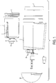
- FIG. 1 is a diagram illustrating an exemplary embodiment of a side view of a vacuum tumbling system.
- a vacuum tumbling system in FIG. 1 includes an inner vacuum tumbling chamber 1 and an outer vacuum chamber 2. As shown in FIG. 1 , the inner vacuum tumbling chamber 1 is initially outside of the outer vacuum chamber 2. However, exemplary embodiments are not limited, and the inner vacuum tumbling chamber 1 may be initially placed inside the outer vacuum chamber 2.
- the inner vacuum tumbling chamber 1 may be used to hold a material to be marinated (e.g., meat), a marinade mixture, and a liquid for the marinade mixture. As shown in FIG. 1 , the inner vacuum tumbling chamber 1 looks very similar to a pot. Further, the inner vacuum tumbling chamber 1 may include fins (not shown) on an inner wall of the inner vacuum tumbling chamber 1. The fins of the vacuum tumbling chamber 1 help to move the material to be marinated to a top of the vacuum tumbling chamber 1.
- the inner vacuum tumbling chamber 1 may include a lid 3.
- the lid 3 has a handle that may be used for removing the inner vacuum tumbling chamber 1 from the outer vacuum chamber 2. Further, the lid 3 may have a watertight seal around the outside.
- a handle of the lid 3 is at an elevated level, in comparison to an inner portion of the lid 3. However, the handle of the lid 3 is at a same or a similar level as an outer rim of the lid 3. Further, the lid 3 may be removable.
- the inner vacuum tumbling chamber 1 may include a small hole 4 in a center of the inner vacuum tumbling chamber 1. Further, the small hole 4 may by recessed at a bottom of the inner vacuum tumbling chamber 1. The small hole 4, which is recessed at the bottom and at the center of the inner vacuum tumbling chamber, is tied into an airtight driving system 8. The airtight driving system 8 runs the tumbling action, and will described below.
- the inner vacuum tumbling chamber 1 When a user wants to place the inner vacuum tumbling chamber 1 into the outer vacuum chamber 2, the inner vacuum tumbling chamber 1 is tilted 15 degrees with respect to a horizontal plane. Since the inner vacuum tumbling chamber 1 is tilted 15 degrees, the inner vacuum chamber 1 has a lid 3 with a watertight seal to prevent liquid from escaping the inner vacuum tumbling chamber 1.
- the inner vacuum tumbling chamber 1 When the user wants to place the inner vacuum tumbling chamber 1 into the outer vacuum chamber 2, the inner vacuum tumbling chamber 1 is drawn into the outer vacuum chamber 2. Further, another small hole (not shown) in a center of the lid 3 allows the vacuum to be pulled in the inner vacuum tumbling chamber 1. The another small hole in the lid 3 also works as a pivot during the tumbling process to hold up the top of the inner vacuum tumbling chamber 1.
- a recess 6 at a bottom of the inner vacuum tumbling chamber 1 ties into the airtight driving system or driver 8, and allows the inner vacuum tumbling chamber 1 to turn during the tumbling process. Further, the inner vacuum tumbling chamber 1 has outer grooves 5 on an outside of the inner vacuum tumbling chamber 1 for inserting the inner vacuum tumbling chamber 1 into the outer vacuum chamber 2.
- the inner vacuum tumbling chamber 1 may be various shapes, including cylindrical, rectangular, hexagonal prism, etc.
- the handle of the lid 3 of the inner vacuum tumbling chamber 1 may have a depressed shape near a center of the lid 3.
- the inner vacuum tumbling chamber 1 may also have no outer grooves 5 on the outside of the inner vacuum tumbling chamber 1.
- the inner vacuum tumbling chamber 1 may have an attachment 9 that attaches to the small hole 4, which is recessed at the bottom of the inner vacuum tumbling chamber 1.
- the attachment 9 may provide a mating of the inner vacuum tumbling chamber 1 to the outer vacuum chamber 2.
- Other embodiments and modifications would be apparent to one of ordinary skill in the art.
- an outer vacuum chamber 2 may be a reinforced chamber in which the inner vacuum tumbling chamber 1 is placed. Further, the reinforced chamber of the outer vacuum chamber 2 may be a location where the vacuum is monitored and pulled.
- the outer vacuum chamber 2 may have a reinforced lid 7.
- the reinforced lid 7 may be removable.
- the reinforced lid 7 has a handle at an elevated level, in comparison to an inner portion of the reinforced lid 7.
- the airtight driving system 8 contains a circuit board, a vacuum pump, a vacuum motor, and a tumbling motor. The vacuum is pulled in the outside chamber through the airtight driving system 8.
- the small hole 4 in the center of the inner vacuum tumbling chamber 1 allows the vacuum to transfer into the inner vacuum tumbling chamber 1 from the outer vacuum chamber 2.
- the airtight driving system 8 may be disposed inside the outer vacuum chamber 2, or may be disposed external to the outer vacuum chamber 2.
- the outer vacuum chamber 2 creates and maintains the vacuum pressure throughout the entire tumbling process by constantly measuring the vacuum pressure, and powering on or off the vacuum pump and the tumbling motor during the tumbling process.
- the tumbling motor maintains the tumble action throughout the tumbling process.
- the vacuum motor maintains the vacuum throughout the tumbling process.
- the vacuum motor is turned on and off based on the vacuum pressure as measured by a vacuum sensor (not shown), which may be provided inside the inner vacuum tumbling chamber 1 or alternatively within the outer vacuum chamber 2.
- the circuit board of the airtight driving system 8 may be used to drive signals to the vacuum tumbling system. Therefore, the circuit board of the airtight driving system 8 may be used to interface to and from the vacuum pump, the vacuum motor, and the tumbling motor.
- the outer vacuum chamber 2 encloses the entire tumbling process. Therefore, the user is protected from injury during the tumbling process. Further, the marinade mixture, the material to be marinated, and the liquid are held within the outer vacuum chamber 2 even if they spill from the inner vacuum chamber 1, and are not exposed (i.e., shown) to the user. Thus, exemplary embodiments disclose a single step process that protects the user from being injured by the internal moving parts.
- the outer vacuum chamber 2 may be powered on and off by pushing an on/off switch.
- the outer vacuum chamber 2 may be powered by an external electrical outlet or an internal battery.
- the circuit board, the vacuum pump, the vacuum motor, and the tumbling motor may be powered by the external electrical outlet or the internal battery.
- the outer vacuum chamber 2 may have various shapes, including cylindrical, rectangular, a hexagonal prism, etc. Further, the outer vacuum chamber 2 may have a mating adapter 11 for mating with the attachment 9 of the inner tumbling vacuum chamber 1.
- the handle of the reinforced lid 7 of the outer vacuum chamber 2 may have a depressed shape near a center of the reinforced lid 7.
- the bottom of the outer vacuum chamber 2 may also be enclosed and covered with a dome covering 10.
- Other embodiments and modifications would be apparent to one of ordinary skill in the art.
- FIG. 2 is a diagram illustrating an exemplary embodiment of a cross-sectional view of a vacuum tumbling system. Since all of the elements of FIG. 2 have been described with reference to FIG. 1 , a detailed description of FIG. 2 will not be repeated.
- FIG. 3 is a diagram illustrating an exemplary embodiment of a cross-section view of a vacuum tumbling system in which the inner tumbling vacuum chamber 1 has been placed in the outer vacuum chamber 2. Since all of the elements of FIG. 3 have been described with reference to FIG. 1 , a detailed description of FIG. 3 will not be repeated.
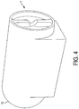
- FIG. 4 is a diagram illustrating an exemplary embodiment of a view of a vacuum tumbling system as viewed by a user.
- the handle of the reinforced lid 7 of the outer vacuum chamber is shown with the depressed shape near the center of the reinforced lid 7. Further, the handle of the reinforced lid 7 is at an elevated level, in comparison to an inner portion of the reinforced lid 7.
- the dome covering 10 is shown at an opposite end of the reinforced lid. Further, in FIG. 4 , the airtight driving system 8 is internally enclosed in the outer vacuum chamber 2
Landscapes
- Life Sciences & Earth Sciences (AREA)
- Engineering & Computer Science (AREA)
- Wood Science & Technology (AREA)
- Zoology (AREA)
- Food Science & Technology (AREA)
- Chemical & Material Sciences (AREA)
- Polymers & Plastics (AREA)
- Meat, Egg Or Seafood Products (AREA)
- Vacuum Packaging (AREA)
- Packages (AREA)
- Control Of Positive-Displacement Pumps (AREA)
Claims (14)
- Vakuumtaumelsystem zum Marinieren eines Materials, wobei das System Folgendes umfasst:einen Vakuumsensor;einen luftdichten Antrieb (8);eine äußere Vakuumkammer (2), die dazu konfiguriert ist, ein Vakuum zu überwachen und zu ziehen;eine innere Vakuumtaumelkammer (1), die dazu konfiguriert ist, eine Marinadenmischung, Flüssigkeit und das Material zu umschließen, dazu konfiguriert ist, im Inneren der äußeren Vakuumkammer (2) angeordnet zu sein, und dazu konfiguriert ist, das Vakuum aus der äußeren Vakuumkammer (2) durch ein kleines Loch (4) zu ziehen, das auf einer Bodenfläche der inneren Vakuumtaumelkammer (1) vertieft ist;
wobeidie äußere Vakuumkammer (2) dazu konfiguriert ist, das Vakuum durch den Vakuumsensor zu überwachen, das Vakuum durch den luftdichten Antrieb (8) zu ziehen, und wobei das kleine Loch (4) ermöglicht, das Vakuum von der äußeren Vakuumkammer (2) in die innere Vakuumtaumelkammer (1) zu übertragen, und die innere Vakuumtaumelkammer (1) als Reaktion darauf, dass der luftdichte Antrieb (8) angetrieben wird, zu taumeln. - Vakuumtaumelsystem nach Anspruch 1, wobei das Material Fleisch ist.
- Vakuumtaumelsystem nach Anspruch 1, wobei der luftdichte Antrieb (8) Folgendes umfasst:eine Vakuumpumpe, die dazu konfiguriert ist, auf der Basis des überwachten Vakuums ein- oder ausgeschaltet zu werden;einen Vakuummotor, der dazu konfiguriert ist, die Vakuumpumpe zum Ziehen des Vakuums anzutreiben;eine Taumelmotor, der dazu konfiguriert ist, die innere Vakuumtaumelkammer zu taumeln; undeine Schaltplatte, die dazu konfiguriert ist, mit mindestens einer bzw. einem von der Vakuumpumpe, dem Vakuummotor und dem Taumelmotor verbunden zu werden.
- Vakuumtaumelsystem nach Anspruch 3, wobei die Vakuumpumpe dazu konfiguriert ist, als Reaktion darauf, dass das überwachte Vakuum unter einem vorherbestimmten Niveau ist, eingeschaltet zu werden, oder wobei die Vakuumpumpe dazu konfiguriert ist, als Reaktion darauf, dass das überwachte Vakuum größer gleich einem vorherbestimmten Niveau ist, ausgeschaltet zu werden.
- Vakuumtaumelsystem nach Anspruch 1, wobei der luftdichte Antrieb (8) dazu konfiguriert ist, im Inneren der äußeren Vakuumkammer (2) angeordnet zu sein, oder wobei der luftdichte Antrieb (8) dazu konfiguriert ist, außerhalb der äußeren Vakuumkammer (2) angeordnet zu sein.
- Vakuumtaumelsystem nach Anspruch 1, wobei der luftdichte Antrieb (8) dazu konfiguriert ist, durch eine externe Steckdose angetrieben zu werden, oder wobei der luftdichte Antrieb (8) dazu konfiguriert ist, durch eine Batterie angetrieben zu werden, die von der äußeren Vakuumkammer (2) umschlossen wird.
- Vakuumtaumelsystem nach Anspruch 1, wobei die innere Vakuumtaumelkammer (1) um ungefähr 15 Grad in Bezug auf eine horizontale Ebene geneigt ist, wenn die innere Vakuumtaumelkammer (1) im Inneren der äußeren Vakuumkammer (2) angeordnet ist, oder wobei die innere Vakuumtaumelkammer (1) mindestens eine Finne auf einer Innenwand der inneren Vakuumtaumelkammer (1) umfasst, um das Fleisch zu einem oberen Bereich der inneren Vakuumtaumelkammer (1) zu bewegen.
- Vakuumtaumelsystem nach Anspruch 1, wobei die äußere Vakuumkammer (2) einen Passungsadapter aufweist, der mit einem Anbauteil der inneren Vakuumtaumelkammer zusammenpasst.
- Verfahren zum Marinieren von Material in einem Vakuumtaumelsystem, das einen luftdichten Antrieb (8) umfasst, wobei das Verfahren Folgendes umfasst:Überwachen eines Vakuums in einer äußeren Vakuumkammer (2);Taumeln einer inneren Vakuumtaumelkammer (1), die dazu konfiguriert ist, eine Marinadenmischung, Flüssigkeit und das Material zu umschließen, und dazu konfiguriert ist, im Inneren der äußeren Vakuumkammer (2) angeordnet zu sein; undAufrechterhalten eines vorherbestimmten Vakuumniveaus der äußeren Vakuumkammer (2) auf der Basis eines Werts des überwachten Vakuums,wobei die innere Vakuumtaumelkammer (1) weiterhin dazu konfiguriert ist, das Vakuum aus der äußeren Vakuumkammer (2) durch den luftdichten Antrieb (8) und ein kleines Loch (4) zu ziehen, das auf einer Bodenfläche der inneren Vakuumtaumelkammer (1) vertieft ist, um zu ermöglichen, das Vakuum von der äußeren Vakuumkammer (2) in die innere Vakuumtaumelkammer (1) zu übertragen.
- Verfahren nach Anspruch 9, wobei die innere Vakuumtaumelkammer von dem luftdichten Antrieb (8) getaumelt wird.
- Verfahren nach Anspruch 10, wobei der luftdichte Antrieb (8) Folgendes umfasst:eine Vakuumpumpe, die dazu konfiguriert ist, auf der Basis des überwachten Vakuums ein- oder ausgeschaltet zu werden;einen Vakuummotor, der dazu konfiguriert ist, die Vakuumpumpe zum Ziehen des Vakuums anzutreiben;eine Taumelmotor, der dazu konfiguriert ist, die innere Vakuumtaumelkammer (1) zu taumeln; undeine Schaltplatte, die dazu konfiguriert ist, mit mindestens einer bzw. einem von der Vakuumpumpe, dem Vakuummotor und dem Taumelmotor verbunden zu werden.
- Verfahren nach Anspruch 10, wobei der luftdichte Antrieb (8) dazu konfiguriert ist, im Inneren der äußeren Vakuumkammer (2) angeordnet zu sein, oder wobei der luftdichte Antrieb (8) dazu konfiguriert ist, außerhalb der äußeren Vakuumkammer angeordnet zu sein.
- Verfahren nach Anspruch 10, wobei der luftdichte Antrieb (8) dazu konfiguriert ist, durch eine externe Steckdose angetrieben zu werden, oder wobei der luftdichte Antrieb (8) dazu konfiguriert ist, durch eine Batterie angetrieben zu werden, die von der äußeren Vakuumkammer (2) umschlossen wird.
- Verfahren nach Anspruch 11, wobei die Vakuumpumpe dazu konfiguriert ist, als Reaktion darauf, dass das überwachte Vakuum unter einem vorherbestimmten Niveau ist, eingeschaltet zu werden, oder wobei die Vakuumpumpe dazu konfiguriert ist, als Reaktion darauf, dass das überwachte Vakuum größer gleich dem vorherbestimmten Niveau ist, ausgeschaltet zu werden.
Applications Claiming Priority (2)
| Application Number | Priority Date | Filing Date | Title |
|---|---|---|---|
| US201261669355P | 2012-07-09 | 2012-07-09 | |
| PCT/US2013/049534 WO2014011528A1 (en) | 2012-07-09 | 2013-07-08 | Enclosed vacuum tumbling device |
Publications (3)
| Publication Number | Publication Date |
|---|---|
| EP2869916A1 EP2869916A1 (de) | 2015-05-13 |
| EP2869916A4 EP2869916A4 (de) | 2016-03-09 |
| EP2869916B1 true EP2869916B1 (de) | 2017-11-01 |
Family
ID=49878719
Family Applications (1)
| Application Number | Title | Priority Date | Filing Date |
|---|---|---|---|
| EP13816316.7A Active EP2869916B1 (de) | 2012-07-09 | 2013-07-08 | Taumelvorrichtung in einem geschlossenen vakuum |
Country Status (7)
| Country | Link |
|---|---|
| US (2) | US9288999B2 (de) |
| EP (1) | EP2869916B1 (de) |
| JP (1) | JP6211079B2 (de) |
| AU (1) | AU2013288939B2 (de) |
| CA (1) | CA2877133C (de) |
| MX (1) | MX355655B (de) |
| WO (1) | WO2014011528A1 (de) |
Families Citing this family (11)
| Publication number | Priority date | Publication date | Assignee | Title |
|---|---|---|---|---|
| WO2018079822A1 (ja) * | 2016-10-31 | 2018-05-03 | 大王製紙株式会社 | 清掃用ウェットシートおよび清掃用ウェットシートの製造方法 |
| EP3880048A1 (de) | 2019-03-08 | 2021-09-22 | SharkNinja Operating LLC | Vakuumsystem zur nahrungsmittelverarbeitung |
| CA3123912A1 (en) | 2019-03-08 | 2020-09-17 | Sharkninja Operating Llc | Vacuum food processing system |
| WO2020185691A1 (en) | 2019-03-08 | 2020-09-17 | Sharkninja Operating Llc | Vacuum food processing system |
| USD927256S1 (en) | 2019-06-06 | 2021-08-10 | Sharkninja Operating Llc | Blender |
| USD925270S1 (en) | 2019-06-06 | 2021-07-20 | Sharkninja Operating Llc | Blender |
| USD940500S1 (en) | 2019-06-06 | 2022-01-11 | Sharkninja Operating Llc | Lid |
| USD924007S1 (en) | 2019-06-06 | 2021-07-06 | Sharkninja Operating Llc | Strainer blender accessory |
| CN110384126A (zh) * | 2019-08-14 | 2019-10-29 | 马鞍山市润启新材料科技有限公司 | 一种真空滚揉机 |
| CN110710557A (zh) * | 2019-10-18 | 2020-01-21 | 溆浦县龙潭天然食品有限公司 | 肉类腌制滚揉机 |
| CN116268042B (zh) * | 2022-12-19 | 2024-08-23 | 三只松鼠股份有限公司 | 一种智能食品真空滚揉机 |
Family Cites Families (21)
| Publication number | Priority date | Publication date | Assignee | Title |
|---|---|---|---|---|
| JPS587025B2 (ja) * | 1976-07-21 | 1983-02-08 | 日本電子株式会社 | イオンポンプ排気装置 |
| US4517888A (en) * | 1980-10-14 | 1985-05-21 | Challenge-Cook Brothers, Inc. | Food processor |
| CA1153928A (en) * | 1981-02-23 | 1983-09-20 | Knud Simonsen | Vacuum agitator for meat products and method of processing |
| US4379796A (en) * | 1981-05-22 | 1983-04-12 | The J. M. Smucker Company | Method of concentrating fresh fruits |
| US4421020A (en) | 1981-05-22 | 1983-12-20 | The J. M. Smucker Company | Apparatus for the concentration of fruits |
| US4818550A (en) * | 1988-01-11 | 1989-04-04 | Robert H. Clark, Iii | Apparatus and process for marinating foodstuffs |
| US4994294A (en) * | 1989-09-22 | 1991-02-19 | Bruce Gould | Temperature controlled food processing apparatus and method |
| JPH0797959B2 (ja) * | 1992-06-15 | 1995-10-25 | 株式会社ヒガシモトキカイ | 食肉漬け込み装置 |
| JPH0822202B2 (ja) * | 1992-08-06 | 1996-03-06 | 双葉電機工業株式会社 | 食肉等の回転マッサージ機 |
| DE59407581D1 (de) * | 1993-08-13 | 1999-02-18 | Dorit Food Processing Equipmen | Verfahren und Durchlaufvakuumtumbler zur Behandlung von Nahrungsmitteln |
| US6040013A (en) * | 1994-10-25 | 2000-03-21 | Stephen P. Karales | Vacuum tumbling of meats and other foods |
| US6015580A (en) * | 1996-07-11 | 2000-01-18 | Mays; Ralph C. | Method of tenderizing meat |
| JP3215912B2 (ja) * | 1997-05-14 | 2001-10-09 | 丸大食品株式会社 | ピックル液脱泡装置 |
| US6019034A (en) * | 1999-07-29 | 2000-02-01 | Ford, Sr.; Clifton K. | Apparatus for treatment of liquor |
| US6242025B1 (en) | 1999-08-04 | 2001-06-05 | James Lesky | Method and apparatus for food marinating |
| JP2001246236A (ja) * | 2000-03-07 | 2001-09-11 | Thinky Corp | 攪拌脱泡装置 |
| ATE345050T1 (de) * | 2000-08-23 | 2006-12-15 | Creative Culinary Solutions In | Tumbler zur marinierung von nahrungsmitteln |
| WO2003022073A1 (en) * | 2001-09-07 | 2003-03-20 | Paumen Lawrence J | Food tumbler |
| US7047874B1 (en) * | 2003-11-20 | 2006-05-23 | Eastman Holding Company | Marinade tumbler |
| WO2006125169A1 (en) * | 2005-05-19 | 2006-11-23 | Arra Yeghiayan | Compact apparatus for marinating and tenderizing meat |
| US7670042B2 (en) * | 2006-10-18 | 2010-03-02 | George Cheung | Marinating device |
-
2013
- 2013-07-08 EP EP13816316.7A patent/EP2869916B1/de active Active
- 2013-07-08 WO PCT/US2013/049534 patent/WO2014011528A1/en not_active Ceased
- 2013-07-08 JP JP2015521679A patent/JP6211079B2/ja not_active Expired - Fee Related
- 2013-07-08 CA CA2877133A patent/CA2877133C/en active Active
- 2013-07-08 MX MX2014015870A patent/MX355655B/es active IP Right Grant
- 2013-07-08 US US13/936,577 patent/US9288999B2/en active Active
- 2013-07-08 AU AU2013288939A patent/AU2013288939B2/en not_active Ceased
-
2016
- 2016-02-22 US US15/049,174 patent/US9433226B2/en active Active
Non-Patent Citations (1)
| Title |
|---|
| None * |
Also Published As
| Publication number | Publication date |
|---|---|
| MX355655B (es) | 2018-04-26 |
| CA2877133C (en) | 2019-03-05 |
| JP2015524657A (ja) | 2015-08-27 |
| JP6211079B2 (ja) | 2017-10-11 |
| EP2869916A4 (de) | 2016-03-09 |
| US9288999B2 (en) | 2016-03-22 |
| US20160183582A1 (en) | 2016-06-30 |
| CA2877133A1 (en) | 2014-01-16 |
| MX2014015870A (es) | 2015-08-14 |
| AU2013288939B2 (en) | 2017-06-29 |
| EP2869916A1 (de) | 2015-05-13 |
| AU2013288939A1 (en) | 2015-02-19 |
| WO2014011528A1 (en) | 2014-01-16 |
| US20140010929A1 (en) | 2014-01-09 |
| US9433226B2 (en) | 2016-09-06 |
Similar Documents
| Publication | Publication Date | Title |
|---|---|---|
| EP2869916B1 (de) | Taumelvorrichtung in einem geschlossenen vakuum | |
| JP2014523291A5 (de) | ||
| CA2714522A1 (en) | Processing apparatus and method | |
| ITTO20090014A1 (it) | Macchina per la produzione di gelato ed affini | |
| EP1477421A3 (de) | Siegelvorrichtung für einen Behälter und Verfahren zum Siegeln eines Behälters mittels derselben | |
| KR20190029636A (ko) | 식품을 담는 어플라이언스 및 캡슐 | |
| CN104441001B (zh) | 包括多个辅助切割工具的食物切割附件 | |
| WO2015142699A1 (en) | Transportable mixing system for biological and pharmaceutical materials | |
| US20150245636A1 (en) | Frozen Beverage Preparation Method and Device | |
| ATE377446T1 (de) | Vorrichtung zur herstellung einer granita und eines ähnlichen getränkes | |
| US20080134714A1 (en) | Removable cooler insert | |
| US20110162334A1 (en) | Vacuum apparatus for vacuum compression pack used to store foods | |
| US20160338515A1 (en) | Personal Egg Peeler | |
| JP2018184215A (ja) | 液体状又は半液体状食品の容器を接続するためのコネクタ及びこのようなコネクタと容器とを備える装置 | |
| CN105212017A (zh) | 一种流化床式冻结机 | |
| CN202852161U (zh) | 一种用于复合型中型散装容器中阀门备用启闭装置及容器 | |
| JP2011189277A5 (de) | ||
| CN106152669B (zh) | 冰箱及用于冰箱的速冻方法 | |
| CN203516016U (zh) | 一种便携式充气泵壳体结构 | |
| KR101464467B1 (ko) | 핸드믹서기의 결합구조 | |
| CN208112372U (zh) | 一种带有排水装置的电机 | |
| MY206998A (en) | Water purifier | |
| CN109573120B (zh) | 一种食品包装机 | |
| EP2515641B1 (de) | Verpackung zur aufnahme und konservierung eines einzufrierenden flüssigen stoffes | |
| WO2008055509A3 (en) | A device and a method for separating fish liver |
Legal Events
| Date | Code | Title | Description |
|---|---|---|---|
| PUAI | Public reference made under article 153(3) epc to a published international application that has entered the european phase |
Free format text: ORIGINAL CODE: 0009012 |
|
| 17P | Request for examination filed |
Effective date: 20150206 |
|
| AK | Designated contracting states |
Kind code of ref document: A1 Designated state(s): AL AT BE BG CH CY CZ DE DK EE ES FI FR GB GR HR HU IE IS IT LI LT LU LV MC MK MT NL NO PL PT RO RS SE SI SK SM TR |
|
| AX | Request for extension of the european patent |
Extension state: BA ME |
|
| DAX | Request for extension of the european patent (deleted) | ||
| RA4 | Supplementary search report drawn up and despatched (corrected) |
Effective date: 20160210 |
|
| RIC1 | Information provided on ipc code assigned before grant |
Ipc: A23B 4/26 20060101ALI20160204BHEP Ipc: B01F 9/02 20060101AFI20160204BHEP |
|
| GRAP | Despatch of communication of intention to grant a patent |
Free format text: ORIGINAL CODE: EPIDOSNIGR1 |
|
| STAA | Information on the status of an ep patent application or granted ep patent |
Free format text: STATUS: GRANT OF PATENT IS INTENDED |
|
| INTG | Intention to grant announced |
Effective date: 20170315 |
|
| GRAS | Grant fee paid |
Free format text: ORIGINAL CODE: EPIDOSNIGR3 |
|
| GRAJ | Information related to disapproval of communication of intention to grant by the applicant or resumption of examination proceedings by the epo deleted |
Free format text: ORIGINAL CODE: EPIDOSDIGR1 |
|
| GRAL | Information related to payment of fee for publishing/printing deleted |
Free format text: ORIGINAL CODE: EPIDOSDIGR3 |
|
| STAA | Information on the status of an ep patent application or granted ep patent |
Free format text: STATUS: REQUEST FOR EXAMINATION WAS MADE |
|
| INTC | Intention to grant announced (deleted) | ||
| GRAR | Information related to intention to grant a patent recorded |
Free format text: ORIGINAL CODE: EPIDOSNIGR71 |
|
| STAA | Information on the status of an ep patent application or granted ep patent |
Free format text: STATUS: GRANT OF PATENT IS INTENDED |
|
| GRAA | (expected) grant |
Free format text: ORIGINAL CODE: 0009210 |
|
| STAA | Information on the status of an ep patent application or granted ep patent |
Free format text: STATUS: THE PATENT HAS BEEN GRANTED |
|
| AK | Designated contracting states |
Kind code of ref document: B1 Designated state(s): AL AT BE BG CH CY CZ DE DK EE ES FI FR GB GR HR HU IE IS IT LI LT LU LV MC MK MT NL NO PL PT RO RS SE SI SK SM TR |
|
| INTG | Intention to grant announced |
Effective date: 20170922 |
|
| REG | Reference to a national code |
Ref country code: GB Ref legal event code: FG4D |
|
| REG | Reference to a national code |
Ref country code: CH Ref legal event code: EP Ref country code: AT Ref legal event code: REF Ref document number: 941506 Country of ref document: AT Kind code of ref document: T Effective date: 20171115 |
|
| REG | Reference to a national code |
Ref country code: IE Ref legal event code: FG4D |
|
| REG | Reference to a national code |
Ref country code: DE Ref legal event code: R096 Ref document number: 602013028868 Country of ref document: DE |
|
| REG | Reference to a national code |
Ref country code: CH Ref legal event code: NV Representative=s name: STOLMAR AND PARTNER INTELLECTUAL PROPERTY S.A., CH |
|
| REG | Reference to a national code |
Ref country code: NL Ref legal event code: MP Effective date: 20171101 |
|
| REG | Reference to a national code |
Ref country code: LT Ref legal event code: MG4D |
|
| REG | Reference to a national code |
Ref country code: AT Ref legal event code: MK05 Ref document number: 941506 Country of ref document: AT Kind code of ref document: T Effective date: 20171101 |
|
| PG25 | Lapsed in a contracting state [announced via postgrant information from national office to epo] |
Ref country code: ES Free format text: LAPSE BECAUSE OF FAILURE TO SUBMIT A TRANSLATION OF THE DESCRIPTION OR TO PAY THE FEE WITHIN THE PRESCRIBED TIME-LIMIT Effective date: 20171101 Ref country code: SE Free format text: LAPSE BECAUSE OF FAILURE TO SUBMIT A TRANSLATION OF THE DESCRIPTION OR TO PAY THE FEE WITHIN THE PRESCRIBED TIME-LIMIT Effective date: 20171101 Ref country code: NL Free format text: LAPSE BECAUSE OF FAILURE TO SUBMIT A TRANSLATION OF THE DESCRIPTION OR TO PAY THE FEE WITHIN THE PRESCRIBED TIME-LIMIT Effective date: 20171101 Ref country code: FI Free format text: LAPSE BECAUSE OF FAILURE TO SUBMIT A TRANSLATION OF THE DESCRIPTION OR TO PAY THE FEE WITHIN THE PRESCRIBED TIME-LIMIT Effective date: 20171101 Ref country code: LT Free format text: LAPSE BECAUSE OF FAILURE TO SUBMIT A TRANSLATION OF THE DESCRIPTION OR TO PAY THE FEE WITHIN THE PRESCRIBED TIME-LIMIT Effective date: 20171101 Ref country code: NO Free format text: LAPSE BECAUSE OF FAILURE TO SUBMIT A TRANSLATION OF THE DESCRIPTION OR TO PAY THE FEE WITHIN THE PRESCRIBED TIME-LIMIT Effective date: 20180201 |
|
| PG25 | Lapsed in a contracting state [announced via postgrant information from national office to epo] |
Ref country code: RS Free format text: LAPSE BECAUSE OF FAILURE TO SUBMIT A TRANSLATION OF THE DESCRIPTION OR TO PAY THE FEE WITHIN THE PRESCRIBED TIME-LIMIT Effective date: 20171101 Ref country code: BG Free format text: LAPSE BECAUSE OF FAILURE TO SUBMIT A TRANSLATION OF THE DESCRIPTION OR TO PAY THE FEE WITHIN THE PRESCRIBED TIME-LIMIT Effective date: 20180201 Ref country code: AT Free format text: LAPSE BECAUSE OF FAILURE TO SUBMIT A TRANSLATION OF THE DESCRIPTION OR TO PAY THE FEE WITHIN THE PRESCRIBED TIME-LIMIT Effective date: 20171101 Ref country code: LV Free format text: LAPSE BECAUSE OF FAILURE TO SUBMIT A TRANSLATION OF THE DESCRIPTION OR TO PAY THE FEE WITHIN THE PRESCRIBED TIME-LIMIT Effective date: 20171101 Ref country code: GR Free format text: LAPSE BECAUSE OF FAILURE TO SUBMIT A TRANSLATION OF THE DESCRIPTION OR TO PAY THE FEE WITHIN THE PRESCRIBED TIME-LIMIT Effective date: 20180202 Ref country code: HR Free format text: LAPSE BECAUSE OF FAILURE TO SUBMIT A TRANSLATION OF THE DESCRIPTION OR TO PAY THE FEE WITHIN THE PRESCRIBED TIME-LIMIT Effective date: 20171101 Ref country code: IS Free format text: LAPSE BECAUSE OF FAILURE TO SUBMIT A TRANSLATION OF THE DESCRIPTION OR TO PAY THE FEE WITHIN THE PRESCRIBED TIME-LIMIT Effective date: 20180301 |
|
| REG | Reference to a national code |
Ref country code: FR Ref legal event code: PLFP Year of fee payment: 6 |
|
| PG25 | Lapsed in a contracting state [announced via postgrant information from national office to epo] |
Ref country code: DK Free format text: LAPSE BECAUSE OF FAILURE TO SUBMIT A TRANSLATION OF THE DESCRIPTION OR TO PAY THE FEE WITHIN THE PRESCRIBED TIME-LIMIT Effective date: 20171101 Ref country code: EE Free format text: LAPSE BECAUSE OF FAILURE TO SUBMIT A TRANSLATION OF THE DESCRIPTION OR TO PAY THE FEE WITHIN THE PRESCRIBED TIME-LIMIT Effective date: 20171101 Ref country code: CY Free format text: LAPSE BECAUSE OF FAILURE TO SUBMIT A TRANSLATION OF THE DESCRIPTION OR TO PAY THE FEE WITHIN THE PRESCRIBED TIME-LIMIT Effective date: 20171101 Ref country code: CZ Free format text: LAPSE BECAUSE OF FAILURE TO SUBMIT A TRANSLATION OF THE DESCRIPTION OR TO PAY THE FEE WITHIN THE PRESCRIBED TIME-LIMIT Effective date: 20171101 Ref country code: SK Free format text: LAPSE BECAUSE OF FAILURE TO SUBMIT A TRANSLATION OF THE DESCRIPTION OR TO PAY THE FEE WITHIN THE PRESCRIBED TIME-LIMIT Effective date: 20171101 |
|
| REG | Reference to a national code |
Ref country code: DE Ref legal event code: R097 Ref document number: 602013028868 Country of ref document: DE |
|
| PG25 | Lapsed in a contracting state [announced via postgrant information from national office to epo] |
Ref country code: RO Free format text: LAPSE BECAUSE OF FAILURE TO SUBMIT A TRANSLATION OF THE DESCRIPTION OR TO PAY THE FEE WITHIN THE PRESCRIBED TIME-LIMIT Effective date: 20171101 Ref country code: SM Free format text: LAPSE BECAUSE OF FAILURE TO SUBMIT A TRANSLATION OF THE DESCRIPTION OR TO PAY THE FEE WITHIN THE PRESCRIBED TIME-LIMIT Effective date: 20171101 Ref country code: IT Free format text: LAPSE BECAUSE OF FAILURE TO SUBMIT A TRANSLATION OF THE DESCRIPTION OR TO PAY THE FEE WITHIN THE PRESCRIBED TIME-LIMIT Effective date: 20171101 Ref country code: PL Free format text: LAPSE BECAUSE OF FAILURE TO SUBMIT A TRANSLATION OF THE DESCRIPTION OR TO PAY THE FEE WITHIN THE PRESCRIBED TIME-LIMIT Effective date: 20171101 |
|
| PLBE | No opposition filed within time limit |
Free format text: ORIGINAL CODE: 0009261 |
|
| STAA | Information on the status of an ep patent application or granted ep patent |
Free format text: STATUS: NO OPPOSITION FILED WITHIN TIME LIMIT |
|
| 26N | No opposition filed |
Effective date: 20180802 |
|
| PG25 | Lapsed in a contracting state [announced via postgrant information from national office to epo] |
Ref country code: SI Free format text: LAPSE BECAUSE OF FAILURE TO SUBMIT A TRANSLATION OF THE DESCRIPTION OR TO PAY THE FEE WITHIN THE PRESCRIBED TIME-LIMIT Effective date: 20171101 |
|
| PG25 | Lapsed in a contracting state [announced via postgrant information from national office to epo] |
Ref country code: LU Free format text: LAPSE BECAUSE OF NON-PAYMENT OF DUE FEES Effective date: 20180708 Ref country code: MC Free format text: LAPSE BECAUSE OF FAILURE TO SUBMIT A TRANSLATION OF THE DESCRIPTION OR TO PAY THE FEE WITHIN THE PRESCRIBED TIME-LIMIT Effective date: 20171101 |
|
| REG | Reference to a national code |
Ref country code: BE Ref legal event code: MM Effective date: 20180731 |
|
| REG | Reference to a national code |
Ref country code: IE Ref legal event code: MM4A |
|
| PG25 | Lapsed in a contracting state [announced via postgrant information from national office to epo] |
Ref country code: IE Free format text: LAPSE BECAUSE OF NON-PAYMENT OF DUE FEES Effective date: 20180708 |
|
| PG25 | Lapsed in a contracting state [announced via postgrant information from national office to epo] |
Ref country code: BE Free format text: LAPSE BECAUSE OF NON-PAYMENT OF DUE FEES Effective date: 20180731 |
|
| PG25 | Lapsed in a contracting state [announced via postgrant information from national office to epo] |
Ref country code: MT Free format text: LAPSE BECAUSE OF NON-PAYMENT OF DUE FEES Effective date: 20180708 |
|
| PG25 | Lapsed in a contracting state [announced via postgrant information from national office to epo] |
Ref country code: TR Free format text: LAPSE BECAUSE OF FAILURE TO SUBMIT A TRANSLATION OF THE DESCRIPTION OR TO PAY THE FEE WITHIN THE PRESCRIBED TIME-LIMIT Effective date: 20171101 |
|
| PG25 | Lapsed in a contracting state [announced via postgrant information from national office to epo] |
Ref country code: HU Free format text: LAPSE BECAUSE OF FAILURE TO SUBMIT A TRANSLATION OF THE DESCRIPTION OR TO PAY THE FEE WITHIN THE PRESCRIBED TIME-LIMIT; INVALID AB INITIO Effective date: 20130708 Ref country code: PT Free format text: LAPSE BECAUSE OF FAILURE TO SUBMIT A TRANSLATION OF THE DESCRIPTION OR TO PAY THE FEE WITHIN THE PRESCRIBED TIME-LIMIT Effective date: 20171101 |
|
| PG25 | Lapsed in a contracting state [announced via postgrant information from national office to epo] |
Ref country code: MK Free format text: LAPSE BECAUSE OF NON-PAYMENT OF DUE FEES Effective date: 20171101 |
|
| PG25 | Lapsed in a contracting state [announced via postgrant information from national office to epo] |
Ref country code: AL Free format text: LAPSE BECAUSE OF FAILURE TO SUBMIT A TRANSLATION OF THE DESCRIPTION OR TO PAY THE FEE WITHIN THE PRESCRIBED TIME-LIMIT Effective date: 20171101 |
|
| REG | Reference to a national code |
Ref country code: DE Ref legal event code: R079 Ref document number: 602013028868 Country of ref document: DE Free format text: PREVIOUS MAIN CLASS: B01F0009020000 Ipc: B01F0029600000 |
|
| P01 | Opt-out of the competence of the unified patent court (upc) registered |
Effective date: 20230530 |
|
| PGFP | Annual fee paid to national office [announced via postgrant information from national office to epo] |
Ref country code: DE Payment date: 20250729 Year of fee payment: 13 |
|
| PGFP | Annual fee paid to national office [announced via postgrant information from national office to epo] |
Ref country code: GB Payment date: 20250728 Year of fee payment: 13 |
|
| PGFP | Annual fee paid to national office [announced via postgrant information from national office to epo] |
Ref country code: FR Payment date: 20250725 Year of fee payment: 13 |
|
| PGFP | Annual fee paid to national office [announced via postgrant information from national office to epo] |
Ref country code: CH Payment date: 20250801 Year of fee payment: 13 |