EP2869436B1 - Vibration damage repair in dynamoelectric machines - Google Patents
Vibration damage repair in dynamoelectric machines Download PDFInfo
- Publication number
- EP2869436B1 EP2869436B1 EP14190170.2A EP14190170A EP2869436B1 EP 2869436 B1 EP2869436 B1 EP 2869436B1 EP 14190170 A EP14190170 A EP 14190170A EP 2869436 B1 EP2869436 B1 EP 2869436B1
- Authority
- EP
- European Patent Office
- Prior art keywords
- stator
- absorbing material
- vibration
- liquid based
- stator core
- Prior art date
- Legal status (The legal status is an assumption and is not a legal conclusion. Google has not performed a legal analysis and makes no representation as to the accuracy of the status listed.)
- Active
Links
- 230000008439 repair process Effects 0.000 title description 13
- 239000011358 absorbing material Substances 0.000 claims description 93
- 239000007788 liquid Substances 0.000 claims description 78
- 238000000034 method Methods 0.000 claims description 38
- XEEYBQQBJWHFJM-UHFFFAOYSA-N iron Substances [Fe] XEEYBQQBJWHFJM-UHFFFAOYSA-N 0.000 claims description 26
- 238000009423 ventilation Methods 0.000 claims description 26
- 229910052742 iron Inorganic materials 0.000 claims description 24
- 239000000463 material Substances 0.000 claims description 18
- 239000011152 fibreglass Substances 0.000 claims description 9
- 229920002050 silicone resin Polymers 0.000 claims description 9
- 229920001296 polysiloxane Polymers 0.000 claims description 5
- 239000004593 Epoxy Substances 0.000 claims description 2
- JOYRKODLDBILNP-UHFFFAOYSA-N Ethyl urethane Chemical compound CCOC(N)=O JOYRKODLDBILNP-UHFFFAOYSA-N 0.000 claims description 2
- 239000006260 foam Substances 0.000 claims description 2
- 229920000728 polyester Polymers 0.000 claims description 2
- 125000006850 spacer group Chemical group 0.000 description 26
- 238000002347 injection Methods 0.000 description 16
- 239000007924 injection Substances 0.000 description 16
- 230000008878 coupling Effects 0.000 description 5
- 238000010168 coupling process Methods 0.000 description 5
- 238000005859 coupling reaction Methods 0.000 description 5
- 208000027418 Wounds and injury Diseases 0.000 description 2
- 238000009434 installation Methods 0.000 description 2
- 238000003475 lamination Methods 0.000 description 2
- 239000007787 solid Substances 0.000 description 2
- 208000035874 Excoriation Diseases 0.000 description 1
- 238000005299 abrasion Methods 0.000 description 1
- 230000015556 catabolic process Effects 0.000 description 1
- 230000000295 complement effect Effects 0.000 description 1
- 238000006731 degradation reaction Methods 0.000 description 1
- 230000006866 deterioration Effects 0.000 description 1
- 238000010586 diagram Methods 0.000 description 1
- 230000000694 effects Effects 0.000 description 1
- 239000013536 elastomeric material Substances 0.000 description 1
- 238000010292 electrical insulation Methods 0.000 description 1
- 238000005470 impregnation Methods 0.000 description 1
- 238000003780 insertion Methods 0.000 description 1
- 230000037431 insertion Effects 0.000 description 1
- 239000007791 liquid phase Substances 0.000 description 1
- 239000000203 mixture Substances 0.000 description 1
- 238000013021 overheating Methods 0.000 description 1
- 239000002245 particle Substances 0.000 description 1
- 239000004033 plastic Substances 0.000 description 1
- 238000010248 power generation Methods 0.000 description 1
- 238000005086 pumping Methods 0.000 description 1
- 229910001220 stainless steel Inorganic materials 0.000 description 1
- 239000010935 stainless steel Substances 0.000 description 1
- 239000013589 supplement Substances 0.000 description 1
- 230000002459 sustained effect Effects 0.000 description 1
- 238000004804 winding Methods 0.000 description 1
Images


Classifications
-
- H—ELECTRICITY
- H01—ELECTRIC ELEMENTS
- H01B—CABLES; CONDUCTORS; INSULATORS; SELECTION OF MATERIALS FOR THEIR CONDUCTIVE, INSULATING OR DIELECTRIC PROPERTIES
- H01B13/00—Apparatus or processes specially adapted for manufacturing conductors or cables
- H01B13/0026—Apparatus for manufacturing conducting or semi-conducting layers, e.g. deposition of metal
-
- H—ELECTRICITY
- H02—GENERATION; CONVERSION OR DISTRIBUTION OF ELECTRIC POWER
- H02K—DYNAMO-ELECTRIC MACHINES
- H02K15/00—Methods or apparatus specially adapted for manufacturing, assembling, maintaining or repairing of dynamo-electric machines
- H02K15/0006—Disassembling, repairing or modifying dynamo-electric machines
-
- H—ELECTRICITY
- H02—GENERATION; CONVERSION OR DISTRIBUTION OF ELECTRIC POWER
- H02K—DYNAMO-ELECTRIC MACHINES
- H02K15/00—Methods or apparatus specially adapted for manufacturing, assembling, maintaining or repairing of dynamo-electric machines
- H02K15/12—Impregnating, heating or drying of windings, stators, rotors or machines
-
- H—ELECTRICITY
- H02—GENERATION; CONVERSION OR DISTRIBUTION OF ELECTRIC POWER
- H02K—DYNAMO-ELECTRIC MACHINES
- H02K3/00—Details of windings
- H02K3/46—Fastening of windings on the stator or rotor structure
- H02K3/48—Fastening of windings on the stator or rotor structure in slots
Definitions
- the disclosure relates generally to dynamoelectric machines. More particularly, the present disclosure relates to a method for reducing or repairing vibration damage in a stator core, and a dynamoelectric machine resulting from the method.
- Dynamoelectric machines such as generators, may be used in power plants, cogeneration plants, vehicles, or other implementations for converting mechanical energy into electrical energy.
- Dynamoelectric machines may include several laminations stacked into a "stator core," and used to create magnetic conductance for power generation.
- a stator armature composed of one or more stator bars may be wound throughout the stator core.
- the stator core can include stator bar slots for holding stator bars and other components.
- a side ripple spring can be coupled to the stator core or the stator bar.
- stator bars housed in stator bar slots can flexibly occupy any remaining gaps between the stator bar and the stator core.
- a different topic with stator bars housed in stator bar slots is corona protection.
- US 4095627 A1 describes to inject an uncured semi-conducting elastomeric material between coil sides and slot walls by an injector tool to prevent eddy currents between the corresponding parts.
- stator bars contained in a stator core can suffer damage from stator vibrations.
- a side ripple spring on the stator core or the stator bars can reduce this damage by absorbing the stator vibrations.
- side ripple springs themselves can also experience wear and degradation over time.
- a first aspect of the invention provides a method for reducing vibration damage in a stator, the method comprising: applying, from within a ventilation slot of a stator core, a liquid based vibration-absorbing material onto a side ripple spring, the side ripple spring being in contact with a stator bar and the stator core; and allowing the liquid based vibration-absorbing material to cure, wherein the cured vibration-absorbing material remains in contact with the side ripple spring to absorb stator vibrations.
- a second aspect of the invention provides a dynamoelectric machine according to claim 13.
- the present disclosure relates to methods for reducing vibration-caused damage in a stator core of a dynamoelectric machine.
- the method can repair side ripple springs and end iron regions of a stator core.
- Dynamoelectric machine 2 can include a rotating component (not shown) inside of a stator core 10.
- Stator core 10 can be designed to have a substantially circular cross-sectional geometry with a hollow center.
- a plurality of circumferentially spaced stator bar slots 12 may be present along the interior of stator core 10.
- each stator bar slot 12 may be designed to contain one or more "stator bars," an assembly of which may be called a "stator armature.”
- Portions of each stator bar slot 12 can include one or more dovetails 14.
- Dovetails 14 can engage portions of stator bars or stator armature by outwardly extending portions, such as wedges, as described elsewhere herein.
- the region of stator core 10 where the radially inner surface of stator core 10 tapers away from the core of dynamoelectric machine 2 may be referred to as an "end-iron region" 16.
- end-iron region 16 dovetails 14 may vanish, as shown in FIG. 1 , as the radially inner surface of stator core 10 steps down.
- end-iron region 16 can also be known as an "end stepping region.”
- stator bar slots 12 can include a stator armature 20 installed therein.
- Stator armature 20 may also be referred to as a "stator winding.”
- Stator armature 20 can include a first stator bar 22 coupled to a second stator bar 24.
- stator armature 20 may be composed of several discrete components, as shown by example in FIG. 2 , or may be a single continuous piece.
- Stator armature 20 can be wound through several stator bar slots 12 within stator core 10.
- a radially inner side of stator armature 20 can be coupled to a wedge 26. Wedge 26 can engage dovetail 14 and be positioned therein, thereby reducing radial movement of stator armature 20.
- a top ripple spring 28 can couple wedge 26 and stator armature 20 to each other. Top ripple spring 28 and wedge 26, together, can reduce movement of stator armature 20 in a radial direction relative to stator core 10. Top ripple spring 28 can also absorb some vibrations acting on stator armature 20.
- first stator bar 22 and/or second stator bar 24 of stator armature 20 can include one or more layers of armor 29. Armor 29 can electrically insulate and/or protect stator armature 20 from stator vibrations.
- stator armature 20 can experience alternating electromagnetic loads and/or electrical discharges. These effects may cause stator core 10 to vibrate, and the resulting vibrations may spread throughout dynamoelectric machine 2. In some cases, stator vibrations can damage the various components installed within stator bar slot 12. Stator vibrations can also cause stator armature 20 and/or armor 29 to become loose and susceptible to further damage.
- One or more side ripple springs 30A, 30B can be in contact with stator armature 20, and may be installed to absorb stator vibrations and reduce movement by stator armature 20 within the plane of stator bar slot 12.
- Side ripple springs 30A, 30B can be coupled to the side of a stator bar slot 12.
- First stator bar 22 and/or second stator bar 24 can contact side ripple springs 30A, 30B.
- Side ripple springs 30A, 30B can be made of fiberglass or similar flexible materials.
- Side ripple springs 30A, 30B being flexible, can accommodate stator bars 20 of different shapes and sizes.
- stator core 10 can include spacer blocks 32 to define ventilation slots in stator core 10 as described herein. Ventilation slots defined by spacer blocks 32 can allow hot air, generated during the operation of dynamoelectric machine 2 ( FIG. 1 ), to escape stator bar slot 12 and thereby prevent stator armature 20 from overheating.
- FIG. 3 a perspective view of slot 12 and stator armature 20 is shown.
- the shape of dynamoelectric machine 2 ( FIG. 1 ) and/or stator core 10 can be substantially circular.
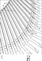
- One or more radially oriented ventilation slots 34 at various axial positions can extend circumferentially throughout stator core 10.
- ventilation slots 34 can allow hot air to escape stator core 10.
- Ventilation slots 34 can extend between each stator armature 20 and corresponding spacer blocks 32. The width of each ventilation slot 34 may increase as ventilation slot 34 extends radially from the center of dynamoelectric machine 2 ( FIG. 1 ).
- a user can perform methods according to the present disclosure within any one of several ventilation slots 34 within stator core 10.
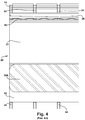
- FIG. 4 shows a longitudinal cross section of stator armature 20 within stator core 10.
- stator armature 20 can include a first stator bar 22 and a second stator bar 24.
- stator armature 20 may be in contact with side ripple spring 30A, and top ripple spring 28 (coupled to wedge 26).
- the surface of one stator armature 20 can be perpendicular to several ventilation slots 34.
- side ripple spring 30A can intersect multiple ventilation slots 34 despite being in contact with one stator armature 20.
- FIG. 5 an example of a tool 40 for injecting a liquid based vibration-absorbing material in a method according to embodiments of the present disclosure is shown.
- a liquid based vibration-absorbing material can include any currently known or later discovered materials capable of absorbing stator vibrations within stator core 10 ( FIGS. 1-4 ).
- the liquid based vibration-absorbing material can have high viscosity when applied.
- the liquid based vibration-absorbing material can cure into a solid state.
- the liquid based vibration-absorbing material after curing, can remain in contact with side ripple springs 30A, 30B ( FIGS.
- the liquid based vibration-absorbing material can include a conductive or non-conductive room-temperature vulcanizing material.
- the liquid based vibration-absorbing material can include a non-conductive or conductive room-temperature vulcanizing silicone (CRTV).
- the liquid based vibration-absorbing material can include epoxy, polyester, and/or urethane foam.
- Tool 40 may include an injection line 42 terminating at an injection port 44 at an end of tool 40.
- Injection line 42 shown in the form of a tube, can deliver a liquid based vibration-absorbing material from coupler 46.
- Injection line 42 can be composed of a flexible material, such as a plastic, to allow tool 40 to be used more efficiently.
- Coupler 46 can be coupled to a reserve (not shown) and/or other hoses, supplies, components, etc. for delivering a liquid based vibration-absorbing material.
- tool 40 is shown by example to have an injection port 44 perpendicular to a surface 45 of tool 40, injection port 44 can have any desired angle.
- injection port 44 can be oriented approximately forty-five degrees relative to the surface of stator armature 20 ( FIGS. 2-4 ). Modifying the orientation of injection port 44 can enhance the application of liquid based vibration-absorbing material injected from tool 40 by causing injected material to cover a greater surface area.
- tool 40 can include an injection needle 48.
- Injection needle 48 can optionally have a sloped face designed to complement ventilation slot 34 ( FIG. 3 ), thereby allowing tool 40 to enter and remain within ventilation slot 34.
- tool 40 can include a back spine 50 configured to contact stator components at or near the location of injection port 44.
- back spine 50 can be a hardened, stainless steel component which structurally supports tool 40 at a point where a user desires to apply a liquid based vibration-absorbing material.
- tool 40 can include adjustable depth stop 52, which can be placed upon a surface of stator core 10 ( FIGS. 1-4 ) or other area during use of tool 40.
- adjustable depth stop 52 on tool 40 can be adjusted for installation of liquid based vibration-absorbing materials in ventilation slots of varying size. For example, a user may align injection port 44 of tool 40 with stator armature 20 or stator core 10, and place depth stop 52 upon a component (e.g., a block or lamination) of stator core 10 ( FIGS. 1-4 ) to keep tool 40 in place while material is being applied therefrom.
- a component e.g., a block or lamination
- tool 40 for applying a liquid based vibration-absorbing material can include a hypodermic needle, a borescope with a liquid delivery channel, or any alternative embodiment described herein.
- Other currently known or later developed tools and/or devices for applying a liquid based vibration-absorbing material can also be applied in methods according to the present disclosure.
- FIG. 6 an embodiment of a method for reducing vibration damage in a stator is shown.
- One or more side ripple springs 30A, 30B can lose mass or volume upon sustaining damage from stator vibrations. For example, some particles of the material making up side ripple springs 30A, 30B can separate from the structure of side ripple springs 30A, 30B during the operation of dynamoelectric machine 2 ( FIG. 1 ) as a result of stator core 10 being weakened from continued use. Side ripple springs 30A, 30B may have less capacity to absorb stator vibrations if the loss of materials becomes significant. The present disclosure allows a user to repair and protect side ripple springs 30A, 30B.
- a user can apply a liquid based vibration-absorbing material onto a stator component to absorb stator vibrations.
- the applied liquid based vibration-absorbing material may be applied from ventilation slot 34 of stator core 10.
- a user can apply the liquid based vibration-absorbing material with tool 40 by injecting the liquid-based vibration-absorbing material from injection port 44. If desired, back spine 50 of tool 40 can be held securely at a point of application by being aligned with a spacer 54.
- a user can press tool 40 against stator armature 20 and/or stator core 10. Contact between tool 40 and stator armature 20 or stator core 10 can stop any liquid based vibration-absorbing material from leaving stator slot 12 ( FIG. 2 ) and entering ventilation slot 34.
- a corresponding spacer 54 can be in contact with or coupled to back spine 50 to provide additional support.
- a user can insert spacer 54 into ventilation slot 34 following insertion of tool 40.
- Spacer 54 can be substantially aligned with a desired point of application.
- Tool 40 can then be positioned alongside spacer 54 to occupy the remainder of ventilation slot 34.
- tool 40 and spacer 54 can occupy substantially all of ventilation slot 34 between spacer block 32 and stator armature 20.
- Liquid based vibration-absorbing material upon leaving tool 40, can contact side ripple springs 30A, 30B.
- the applied liquid based vibration-absorbing material can also contact stator core 10, stator armature 20, and/or armor 29 upon application.
- the liquid based vibration-absorbing material may be applied from between side ripple spring 30A, 30B and stator core 10.
- Embodiments of the disclosed method can include inserting tool 40 into ventilation slot 34 to orient injection port 44 towards stator armature 20 and/or side ripple springs 30A, 30B. Orienting injection port 44 in this manner can stop the liquid based vibration-absorbing material from entering ventilation slot 34. This approach can also cause any applied liquid based vibration-absorbing material to enter stator core slot 12 ( FIG. 2 ) directly from injection port 44. Thus, liquid based vibration-absorbing material can be prevented from entering ventilation slot 34 following its application.
- Vibration-absorbing materials used in embodiments of the present disclosure can at least partially be in liquid phase when applied, and then cure at a desired location.
- a user can apply a liquid based vibration-absorbing material onto a stator component (e.g., side ripple springs 30A, 30B) where the liquid based vibration-absorbing material can cure.
- the liquid based vibration-absorbing material can become solid and/or substantially immobile. In this manner, the liquid based vibration-absorbing material can remain in contact with side ripple springs 30A, 30B and other components such as stator core 10, stator armature 20, and/or armor 29.
- a user may choose liquid based vibration-absorbing materials with other advantageous properties.
- the liquid based vibration-absorbing material can also be electrically insulative, to prevent electrical shorts to ground from stator core 10, stator armature 20, and/or armor 29.
- the applied liquid based vibration-absorbing material can also act as a charge dissipater to prevent corona from appearing throughout stator core 10 during operation. Corona are points of damage from electrical charges that may arc off of stator armature 20 and/or armor 29 into stator core 10 through side ripple springs 30A, 30B. Embodiments of the present disclosure can thus repair damage and deterioration in side ripple springs 30A, 30B, stator armature 20, and/or armor 29 resulting from electrical corona in addition to damage from stator vibrations.
- back spine 50 of tool 40 can include a depth guide 56 to indicate the depth to which a user has inserted tool 40.
- applying a liquid based vibration-absorbing material to side ripple spring 30A can cause the material to enter stator bar slot 12 to contact side ripple spring 30A and stator core 10. Additionally or alternatively, the liquid based vibration-absorbing material can substantially fill a vacant space of stator bar slot 12 between side ripple spring 30A and stator core 10.
- each side ripple spring 30A can have a "trough" section 57.
- Trough section 57 can refer to a portion of side ripple spring 30A underneath a surface where side ripple spring 30A is in contact with stator core 10 or stator armature 20.
- liquid based vibration-absorbing material from tool 40 can enter trough section 57 of side ripple spring 30A to substitute, replenish, and/or impregnate any materials damaged from stator vibrations.
- the liquid based vibration-absorbing material can remain in place to increase the lateral stiffness of stator armature 20 and/or armor 29 to improve or replenish resistance to stator vibrations.
- Side ripple spring 30A can include fiberglass and/or other flexible materials. As dynamoelectric machine 2 ( FIG. 1 ) operates, stator vibrations can damage fiberglass in side ripple spring 30A. Methods according to the present disclosure can repair damage to side ripple spring 30A through applying a liquid based vibration-absorbing material that includes a silicone resin configured to impregnate the fiberglass. For example, a silicone resin in a liquid based vibration-absorbing material can enter trough 57 to impregnate the fiberglass. The impregnation of liquid based vibration-absorbing material can repair side ripple springs 30A and/or increase the resistance of side ripple springs 30A to stator vibrations. The cured vibration-absorbing material can thereafter remain in contact with side ripple spring 30A. As a result, the cured vibration absorbing material becomes a component of dynamoelectric machine 2 ( FIG. 1 ) and protects the components thereof from the various forms of damage described herein.
- a liquid based vibration-absorbing material that includes a silicone resin configured to impregnate the fiberglass.
- Embodiments of the present disclosure can include also include contacting stator core 10, stator armature 20 (including armor 29 provided thereon), and side ripple spring 30A with the applied liquid based vibration-absorbing material.
- the applied material by contacting several components within dynamoelectric machine 2 ( FIG. 1 ), can supplement or repair portions of several stator components previously damaged by stator vibrations.
- the liquid based vibration-absorbing material once cured, can fill a gap between side ripple spring 30A and stator core 10.
- One or more vibration-induced cavities 59 may form upon stator armature 20, armor 29, and/or side ripple springs 30A as a type of vibration damage sustained by stator core 10.
- the applied liquid based vibration-absorbing materials can enter and fill vibration-induced cavities 59 of side ripple springs 30A.
- material used to repair side ripple spring 30A can also fill and repair vibration-induced cavities 59 present on stator core 10, stator armature 20, and/or armor 29. Applying a liquid based vibration absorbing material to vibration-induced cavity 59 can eliminate this form of damage in addition to repairing side ripple spring 30A.
- FIG. 8 a further embodiment of a method for reducing vibration damage in a stator is shown.
- the method can include applying a liquid based vibration-absorbing material within an end-iron region 16 (designated by accompanying phantom line).
- end-iron region 16 can include a section where the radially inner surface of stator core 10 steps radially, and any corresponding dovetails 14 ( FIG. 1 ) may vanish.
- a user can position tool 40 within end-iron region 16 and apply a liquid based vibration-absorbing material from within ventilation slot 34.
- end-iron region 16 may not include side ripple springs therein.
- liquid based vibration-absorbing material from tool 40 can cure within both end-iron region 16 and any side ripple springs FIGS. 2-4 , 6 , 7 ) located elsewhere by traveling through stator bar slot 12 before curing.
- the width of ventilation slot 34 may be too large for tool 40 to be secured on only one spacer 54.
- one or more additional spacers 58 can also be used to further stabilize tool 40.
- spacer 54 and additional spacers 58 can allow tool 40 to be deployed in a variety of situations.
- Tool 40 can be coupled to hose 60 at coupler 46.
- Hose 60 can deliver (e.g., by pumping) a liquid based vibration-absorbing material from a bulk supply (not shown), allowing large quantities of a liquid based vibration-absorbing material to be applied within stator core 10.
- a spacer handle 62 can move spacer 54 and/or additional spacer 58 to a desired location.
- Spacer handle 62 can be connected to spacer 54 and/or additional spacer 58 through a spacer coupling 64.
- Spacer coupling 64 can include any device for coupling which is capable of moving spacer 54 and/or additional spacer 58 to various positions.
- spacer coupling 64 can be a mechanically actuated device.
- spacer coupling 64 can include a rod, a tube, a line, a shaft, or any other mechanical components currently known or later developed.
- stator armature 20 may lack a wedge 26 ( FIG. 2 ) and top ripple spring 28 ( FIG. 2 ), thereby having reduced capacity to absorb radial stator vibrations.
- a vibration-absorbing material may be applied to stator armature 20 and/or stator core 10 within end-iron region 16.
- portions of end-iron region 16 may include side ripple springs 30A, 30B ( FIGS. 2-4 , 6 , 7 ), and liquid based vibration-absorbing material may contact and cure upon side ripple springs 30A, 30B ( FIGS. 2-4 , 6 , 7 ) according to other embodiments of the disclosure described elsewhere herein.
- the invention provides a dynamoelectric machine resulting from a method according to the present disclosure.
- embodiments of the present disclosure can include dynamoelectric machine 2 having stator bar slot 12.
- Stator armature 20 can be installed within stator bar slot 12 within end-iron region 16.
- side ripple springs 30A, 30B can also be present within end-iron region 16 between stator armature 20 and/or stator core 10.
- stator bar slot 12 can include a liquid based vibration-absorbing material 66 injected within stator bar slot 12 to absorb stator vibrations.
- Liquid based vibration-absorbing material 66 can include vibration-absorbing materials discussed elsewhere herein, such as non-conductive room temperature vulcanizing silicone, and therefore absorb stator vibrations acting on stator core 10.
- Liquid based vibration-absorbing material 66 can be injected following the assembly of dynamoelectric machine 2. More specifically, liquid based vibration-absorbing material 66 can be injected following the installation of stator armature 20.
- liquid based vibration-absorbing material 66 can be present in at least a portion of end-iron region 16.
- liquid based vibration-absorbing material 66 can be in contact with stator core 10 and/or stator armature 20 (including armor 29 ( FIGS. 2 , 3 , 6-9 ) provided thereon).
- embodiments of the present disclosure also extend to dynamoelectric machines and stator cores that have been repaired or equipped according to the methods described herein.
- vibration-absorbing material 66 may include a silicone resin. Silicone resin from vibration-absorbing material 66 may enter side ripple springs 30A, 30B to impregnate the fiberglass with the silicone resin, thereby repairing vibration-caused damage to side ripple springs 30A, 30B.
- An advantage that can be realized from the disclosed method and resulting dynamoelectric machines is an ability to repair stator bars within a stator core of a dynamoelectric machine without rewinding or replacing the existing stator bars. Further, the present disclosure contemplates a method for repairing damage to side ripple springs without a need to remove or replace the side ripple springs.
- liquid based vibration-absorbing materials discussed herein can reduce and/or prevent corona damage that may otherwise occur during the operation of a dynamoelectric machine.
- methods and machines according to the present disclosure can increase lateral stiffness in an end-iron region of a stator core, which further repairs damage from or increases resistance to stator vibrations.
- the present disclosure contemplates applying a liquid based vibration-absorbing material at an angle of approximately forty-five degrees relative to the surface of a stator armature or stator core to improve coverage of the applied liquid based vibration-absorbing material, which can decrease the risk of abrasion.
Description
- The disclosure relates generally to dynamoelectric machines. More particularly, the present disclosure relates to a method for reducing or repairing vibration damage in a stator core, and a dynamoelectric machine resulting from the method.
Dynamoelectric machines, such as generators, may be used in power plants, cogeneration plants, vehicles, or other implementations for converting mechanical energy into electrical energy. Dynamoelectric machines may include several laminations stacked into a "stator core," and used to create magnetic conductance for power generation. A stator armature composed of one or more stator bars may be wound throughout the stator core. The stator core can include stator bar slots for holding stator bars and other components. In some cases, a side ripple spring can be coupled to the stator core or the stator bar. In situations where the stator bar does not completely fill a stator bar slot, the side ripple spring can flexibly occupy any remaining gaps between the stator bar and the stator core.
A different topic with stator bars housed in stator bar slots is corona protection. In this contextUS 4095627 A1 describes to inject an uncured semi-conducting elastomeric material between coil sides and slot walls by an injector tool to prevent eddy currents between the corresponding parts.
As a dynamoelectric machine operates, stator bars contained in a stator core can suffer damage from stator vibrations. A side ripple spring on the stator core or the stator bars can reduce this damage by absorbing the stator vibrations. However, side ripple springs themselves can also experience wear and degradation over time. - A first aspect of the invention provides a method for reducing vibration damage in a stator, the method comprising: applying, from within a ventilation slot of a stator core, a liquid based vibration-absorbing material onto a side ripple spring, the side ripple spring being in contact with a stator bar and the stator core; and allowing the liquid based vibration-absorbing material to cure, wherein the cured vibration-absorbing material remains in contact with the side ripple spring to absorb stator vibrations.
- A second aspect of the invention provides a dynamoelectric machine according to claim 13.
- These and other features of the disclosed system will be more readily understood from the following detailed description of the various aspects of the system taken in conjunction with the accompanying drawings that depict various embodiments, in which:
-
FIG. 1 is a perspective partial view of a conventional stator core. -
FIG. 2 is a cross sectional view of a conventional stator bar within a conventional stator bar slot. -
FIG. 3 is a perspective partial view of a conventional stator bar within a stator bar slot. -
FIG. 4 is a longitudinal cross sectional view of a conventional stator bar within a conventional stator core. -
FIG. 5 is a cross sectional view of a tool for applying a liquid based vibration-absorbing material in a method according to an embodiment of the invention. -
FIG. 6 is a cross sectional view of a configuration for applying a liquid based vibration-absorbing material onto a side ripple spring according to an embodiment of the invention. -
FIG. 7 is a perspective partial view of a configuration for applying a liquid based vibration-absorbing material onto a side ripple spring according to an embodiment of the invention. -
FIG. 8 is a perspective partial view of a configuration for applying a liquid based vibration-absorbing material in an end-iron region according to an embodiment of the invention. -
FIG. 9 is a cross sectional view of a liquid based vibration-absorbing material being applied in an end-iron region according to an embodiment of the invention. -
FIG. 10 is a partial cross sectional diagram of a stator bar and stator core according to an embodiment of the invention. - In the following description, reference is made to the accompanying drawings that form a part thereof, and in which is shown by way of illustration specific exemplary embodiments. These embodiments are described in sufficient detail to enable those skilled in the art to practice the present teachings.
Spatially relative terms, such as "below," "lower," "above," "upper," "axial," "radial" and the like, may be used herein for ease of description to describe one element or feature's relationship to another element(s) or feature(s) as illustrated in the figures. Spatially relative terms may be intended to encompass different orientations of the device in use or operation in addition to the orientation depicted in the figures. For example, if the device in the figures is turned over, elements described as "below" or "beneath" other elements or features would then be oriented "above" the other elements or features. Thus, the example term "below" can encompass both an orientation of above and below. The device may be otherwise oriented (rotated 90 degrees or at other orientations) and the spatially relative descriptors used herein interpreted accordingly.
Generally, the present disclosure relates to methods for reducing vibration-caused damage in a stator core of a dynamoelectric machine. In some embodiments, the method can repair side ripple springs and end iron regions of a stator core.
Referring to the drawings,FIG. 1 depicts adynamoelectric machine 2, in which a user can perform methods according to an embodiment of the invention.Dynamoelectric machine 2 can include a rotating component (not shown) inside of astator core 10.Stator core 10 can be designed to have a substantially circular cross-sectional geometry with a hollow center. In addition, a plurality of circumferentially spacedstator bar slots 12 may be present along the interior ofstator core 10. As discussed elsewhere herein, eachstator bar slot 12 may be designed to contain one or more "stator bars," an assembly of which may be called a "stator armature." Portions of eachstator bar slot 12 can include one ormore dovetails 14.Dovetails 14 can engage portions of stator bars or stator armature by outwardly extending portions, such as wedges, as described elsewhere herein. The region ofstator core 10 where the radially inner surface ofstator core 10 tapers away from the core ofdynamoelectric machine 2 may be referred to as an "end-iron region" 16. In end-iron region 16,dovetails 14 may vanish, as shown inFIG. 1 , as the radially inner surface ofstator core 10 steps down. In some contexts, end-iron region 16 can also be known as an "end stepping region." - Turning to
FIG. 2 , an example group of conventional components engaging the inside surfacestator bar slot 12 is shown. One or more ofstator bar slots 12 can include astator armature 20 installed therein.Stator armature 20 may also be referred to as a "stator winding."Stator armature 20 can include afirst stator bar 22 coupled to asecond stator bar 24. In various embodiments,stator armature 20 may be composed of several discrete components, as shown by example inFIG. 2 , or may be a single continuous piece.Stator armature 20 can be wound through severalstator bar slots 12 withinstator core 10. In addition, a radially inner side ofstator armature 20 can be coupled to awedge 26. Wedge 26 can engagedovetail 14 and be positioned therein, thereby reducing radial movement ofstator armature 20. - A
top ripple spring 28 can couplewedge 26 andstator armature 20 to each other.Top ripple spring 28 andwedge 26, together, can reduce movement ofstator armature 20 in a radial direction relative tostator core 10.Top ripple spring 28 can also absorb some vibrations acting onstator armature 20. In addition,first stator bar 22 and/orsecond stator bar 24 ofstator armature 20 can include one or more layers ofarmor 29.Armor 29 can electrically insulate and/or protectstator armature 20 from stator vibrations. - As dynamoelectric machine 2 (
FIG. 1 ) operates,stator armature 20 can experience alternating electromagnetic loads and/or electrical discharges. These effects may causestator core 10 to vibrate, and the resulting vibrations may spread throughoutdynamoelectric machine 2. In some cases, stator vibrations can damage the various components installed withinstator bar slot 12. Stator vibrations can also causestator armature 20 and/orarmor 29 to become loose and susceptible to further damage. - One or more
side ripple springs stator armature 20, and may be installed to absorb stator vibrations and reduce movement bystator armature 20 within the plane ofstator bar slot 12. Side ripple springs 30A, 30B can be coupled to the side of astator bar slot 12.First stator bar 22 and/orsecond stator bar 24 can contact side ripple springs 30A, 30B. Side ripple springs 30A, 30B can be made of fiberglass or similar flexible materials. Side ripple springs 30A, 30B being flexible, can accommodatestator bars 20 of different shapes and sizes. In addition,stator core 10 can include spacer blocks 32 to define ventilation slots instator core 10 as described herein. Ventilation slots defined byspacer blocks 32 can allow hot air, generated during the operation of dynamoelectric machine 2 (FIG. 1 ), to escapestator bar slot 12 and thereby preventstator armature 20 from overheating. - Turning to
FIG. 3 , a perspective view ofslot 12 andstator armature 20 is shown. As described elsewhere herein, the shape of dynamoelectric machine 2 (FIG. 1 ) and/orstator core 10 can be substantially circular. One or more radially orientedventilation slots 34 at various axial positions can extend circumferentially throughoutstator core 10. As discussed elsewhere herein,ventilation slots 34 can allow hot air to escapestator core 10.Ventilation slots 34 can extend between eachstator armature 20 and corresponding spacer blocks 32. The width of eachventilation slot 34 may increase asventilation slot 34 extends radially from the center of dynamoelectric machine 2 (FIG. 1 ). As described in further detail herein, a user can perform methods according to the present disclosure within any one ofseveral ventilation slots 34 withinstator core 10. -
FIG. 4 shows a longitudinal cross section ofstator armature 20 withinstator core 10. As discussed elsewhere herein,stator armature 20 can include afirst stator bar 22 and asecond stator bar 24. In addition,stator armature 20 may be in contact withside ripple spring 30A, and top ripple spring 28 (coupled to wedge 26). As shown inFIG. 4 , the surface of onestator armature 20 can be perpendicular toseveral ventilation slots 34. Similarly,side ripple spring 30A can intersectmultiple ventilation slots 34 despite being in contact with onestator armature 20. - Turning to
FIG. 5 , an example of atool 40 for injecting a liquid based vibration-absorbing material in a method according to embodiments of the present disclosure is shown. Devices similar totool 40 have previously been implemented to deliver materials used for electrical insulation (e.g.,U.S. Patent 4,112,041 ). A liquid based vibration-absorbing material can include any currently known or later discovered materials capable of absorbing stator vibrations within stator core 10 (FIGS. 1-4 ). For instance, the liquid based vibration-absorbing material can have high viscosity when applied. Upon application, the liquid based vibration-absorbing material can cure into a solid state. The liquid based vibration-absorbing material, after curing, can remain in contact with side ripple springs 30A, 30B (FIGS. 2 ,3 ), in addition to stator core 10 (FIGS. 1-4 ), stator armature 20 (FIGS. 2-4 ), and/or armor 29 (FIGS. 2 ,3 ), if desired. In some embodiments, the liquid based vibration-absorbing material can include a conductive or non-conductive room-temperature vulcanizing material. Specifically, the liquid based vibration-absorbing material can include a non-conductive or conductive room-temperature vulcanizing silicone (CRTV). In other embodiments, the liquid based vibration-absorbing material can include epoxy, polyester, and/or urethane foam. -
Tool 40 may include aninjection line 42 terminating at aninjection port 44 at an end oftool 40.Injection line 42, shown in the form of a tube, can deliver a liquid based vibration-absorbing material fromcoupler 46.Injection line 42 can be composed of a flexible material, such as a plastic, to allowtool 40 to be used more efficiently.Coupler 46 can be coupled to a reserve (not shown) and/or other hoses, supplies, components, etc. for delivering a liquid based vibration-absorbing material. Althoughtool 40 is shown by example to have aninjection port 44 perpendicular to asurface 45 oftool 40,injection port 44 can have any desired angle. For example,injection port 44 can be oriented approximately forty-five degrees relative to the surface of stator armature 20 (FIGS. 2-4 ). Modifying the orientation ofinjection port 44 can enhance the application of liquid based vibration-absorbing material injected fromtool 40 by causing injected material to cover a greater surface area. - In an embodiment,
tool 40 can include aninjection needle 48.Injection needle 48 can optionally have a sloped face designed to complement ventilation slot 34 (FIG. 3 ), thereby allowingtool 40 to enter and remain withinventilation slot 34. Further,tool 40 can include aback spine 50 configured to contact stator components at or near the location ofinjection port 44. For example, backspine 50 can be a hardened, stainless steel component which structurally supportstool 40 at a point where a user desires to apply a liquid based vibration-absorbing material. Further,tool 40 can includeadjustable depth stop 52, which can be placed upon a surface of stator core 10 (FIGS. 1-4 ) or other area during use oftool 40. The position ofadjustable depth stop 52 ontool 40 can be adjusted for installation of liquid based vibration-absorbing materials in ventilation slots of varying size. For example, a user may aligninjection port 44 oftool 40 withstator armature 20 orstator core 10, andplace depth stop 52 upon a component (e.g., a block or lamination) of stator core 10 (FIGS. 1-4 ) to keeptool 40 in place while material is being applied therefrom. - In other embodiments,
tool 40 for applying a liquid based vibration-absorbing material can include a hypodermic needle, a borescope with a liquid delivery channel, or any alternative embodiment described herein. Other currently known or later developed tools and/or devices for applying a liquid based vibration-absorbing material can also be applied in methods according to the present disclosure. - Turning to
FIG. 6 , an embodiment of a method for reducing vibration damage in a stator is shown. One or more side ripple springs 30A, 30B can lose mass or volume upon sustaining damage from stator vibrations. For example, some particles of the material making up side ripple springs 30A, 30B can separate from the structure of side ripple springs 30A, 30B during the operation of dynamoelectric machine 2 (FIG. 1 ) as a result ofstator core 10 being weakened from continued use. Side ripple springs 30A, 30B may have less capacity to absorb stator vibrations if the loss of materials becomes significant. The present disclosure allows a user to repair and protect side ripple springs 30A, 30B. - In an embodiment, a user can apply a liquid based vibration-absorbing material onto a stator component to absorb stator vibrations. The applied liquid based vibration-absorbing material may be applied from
ventilation slot 34 ofstator core 10. In some embodiments, a user can apply the liquid based vibration-absorbing material withtool 40 by injecting the liquid-based vibration-absorbing material frominjection port 44. If desired, backspine 50 oftool 40 can be held securely at a point of application by being aligned with aspacer 54. During application, a user can presstool 40 againststator armature 20 and/orstator core 10. Contact betweentool 40 andstator armature 20 orstator core 10 can stop any liquid based vibration-absorbing material from leaving stator slot 12 (FIG. 2 ) and enteringventilation slot 34. A correspondingspacer 54 can be in contact with or coupled to backspine 50 to provide additional support. For example, a user can insertspacer 54 intoventilation slot 34 following insertion oftool 40.Spacer 54 can be substantially aligned with a desired point of application.Tool 40 can then be positioned alongsidespacer 54 to occupy the remainder ofventilation slot 34. As a result,tool 40 andspacer 54 can occupy substantially all ofventilation slot 34 betweenspacer block 32 andstator armature 20. - Liquid based vibration-absorbing material, upon leaving
tool 40, can contact side ripple springs 30A, 30B. The applied liquid based vibration-absorbing material can also contactstator core 10,stator armature 20, and/orarmor 29 upon application. In alternative embodiments, the liquid based vibration-absorbing material may be applied from betweenside ripple spring stator core 10. - Embodiments of the disclosed method can include inserting
tool 40 intoventilation slot 34 to orientinjection port 44 towardsstator armature 20 and/or side ripple springs 30A, 30B. Orientinginjection port 44 in this manner can stop the liquid based vibration-absorbing material from enteringventilation slot 34. This approach can also cause any applied liquid based vibration-absorbing material to enter stator core slot 12 (FIG. 2 ) directly frominjection port 44. Thus, liquid based vibration-absorbing material can be prevented from enteringventilation slot 34 following its application. - Vibration-absorbing materials used in embodiments of the present disclosure can at least partially be in liquid phase when applied, and then cure at a desired location. Thus, a user can apply a liquid based vibration-absorbing material onto a stator component (e.g., side ripple springs 30A, 30B) where the liquid based vibration-absorbing material can cure. Upon curing, the liquid based vibration-absorbing material can become solid and/or substantially immobile. In this manner, the liquid based vibration-absorbing material can remain in contact with side ripple springs 30A, 30B and other components such as
stator core 10,stator armature 20, and/orarmor 29. - A user may choose liquid based vibration-absorbing materials with other advantageous properties. For instance, the liquid based vibration-absorbing material can also be electrically insulative, to prevent electrical shorts to ground from
stator core 10,stator armature 20, and/orarmor 29. In some embodiments, the applied liquid based vibration-absorbing material can also act as a charge dissipater to prevent corona from appearing throughoutstator core 10 during operation. Corona are points of damage from electrical charges that may arc off ofstator armature 20 and/orarmor 29 intostator core 10 through side ripple springs 30A, 30B. Embodiments of the present disclosure can thus repair damage and deterioration in side ripple springs 30A, 30B,stator armature 20, and/orarmor 29 resulting from electrical corona in addition to damage from stator vibrations. - Turning to
FIG. 7 , additional features compatible with the method are shown. As shown by example inFIG. 7 , backspine 50 oftool 40 can include adepth guide 56 to indicate the depth to which a user has insertedtool 40. In an embodiment, applying a liquid based vibration-absorbing material toside ripple spring 30A can cause the material to enterstator bar slot 12 to contactside ripple spring 30A andstator core 10. Additionally or alternatively, the liquid based vibration-absorbing material can substantially fill a vacant space ofstator bar slot 12 betweenside ripple spring 30A andstator core 10. - In another embodiment, the applied liquid based vibration-absorbing material can enter and repair the material composition of
side ripple spring 30A. For example, eachside ripple spring 30A can have a "trough"section 57.Trough section 57 can refer to a portion ofside ripple spring 30A underneath a surface where side ripplespring 30A is in contact withstator core 10 orstator armature 20. In embodiments of the method, liquid based vibration-absorbing material fromtool 40 can entertrough section 57 ofside ripple spring 30A to substitute, replenish, and/or impregnate any materials damaged from stator vibrations. In addition, the liquid based vibration-absorbing material can remain in place to increase the lateral stiffness ofstator armature 20 and/orarmor 29 to improve or replenish resistance to stator vibrations. -
Side ripple spring 30A can include fiberglass and/or other flexible materials. As dynamoelectric machine 2 (FIG. 1 ) operates, stator vibrations can damage fiberglass inside ripple spring 30A. Methods according to the present disclosure can repair damage toside ripple spring 30A through applying a liquid based vibration-absorbing material that includes a silicone resin configured to impregnate the fiberglass. For example, a silicone resin in a liquid based vibration-absorbing material can entertrough 57 to impregnate the fiberglass. The impregnation of liquid based vibration-absorbing material can repair side ripple springs 30A and/or increase the resistance of side ripple springs 30A to stator vibrations. The cured vibration-absorbing material can thereafter remain in contact withside ripple spring 30A. As a result, the cured vibration absorbing material becomes a component of dynamoelectric machine 2 (FIG. 1 ) and protects the components thereof from the various forms of damage described herein. - Embodiments of the present disclosure can include also include contacting
stator core 10, stator armature 20 (includingarmor 29 provided thereon), andside ripple spring 30A with the applied liquid based vibration-absorbing material. The applied material, by contacting several components within dynamoelectric machine 2 (FIG. 1 ), can supplement or repair portions of several stator components previously damaged by stator vibrations. In addition, the liquid based vibration-absorbing material, once cured, can fill a gap betweenside ripple spring 30A andstator core 10. - One or more vibration-induced
cavities 59 may form uponstator armature 20,armor 29, and/or side ripple springs 30A as a type of vibration damage sustained bystator core 10. In some embodiments, the applied liquid based vibration-absorbing materials can enter and fill vibration-inducedcavities 59 of side ripple springs 30A. In other embodiments, material used to repairside ripple spring 30A can also fill and repair vibration-inducedcavities 59 present onstator core 10,stator armature 20, and/orarmor 29. Applying a liquid based vibration absorbing material to vibration-inducedcavity 59 can eliminate this form of damage in addition to repairingside ripple spring 30A. - Turning to
FIG. 8 , a further embodiment of a method for reducing vibration damage in a stator is shown. The method can include applying a liquid based vibration-absorbing material within an end-iron region 16 (designated by accompanying phantom line). As described elsewhere herein, end-iron region 16 can include a section where the radially inner surface ofstator core 10 steps radially, and any corresponding dovetails 14 (FIG. 1 ) may vanish. A user can positiontool 40 within end-iron region 16 and apply a liquid based vibration-absorbing material from withinventilation slot 34. As shown inFIG. 8 , end-iron region 16 may not include side ripple springs therein. However, liquid based vibration-absorbing material fromtool 40 can cure within both end-iron region 16 and any side ripple springsFIGS. 2-4 ,6 ,7 ) located elsewhere by traveling throughstator bar slot 12 before curing. - In some regions of
stator core 10, such asend iron region 16, the width ofventilation slot 34 may be too large fortool 40 to be secured on only onespacer 54. To avoid this problem, one or moreadditional spacers 58 can also be used to further stabilizetool 40. As a result,spacer 54 andadditional spacers 58 can allowtool 40 to be deployed in a variety of situations. - Turning to
FIG. 9 , an additional configuration for applying a liquid based vibration-absorbing material within end-iron region 16 is shown.Tool 40 can be coupled tohose 60 atcoupler 46.Hose 60 can deliver (e.g., by pumping) a liquid based vibration-absorbing material from a bulk supply (not shown), allowing large quantities of a liquid based vibration-absorbing material to be applied withinstator core 10. In addition, aspacer handle 62 can movespacer 54 and/oradditional spacer 58 to a desired location. Spacer handle 62 can be connected to spacer 54 and/oradditional spacer 58 through aspacer coupling 64.Spacer coupling 64 can include any device for coupling which is capable of movingspacer 54 and/oradditional spacer 58 to various positions. In some embodiments,spacer coupling 64 can be a mechanically actuated device. For example,spacer coupling 64 can include a rod, a tube, a line, a shaft, or any other mechanical components currently known or later developed. - In end-
iron region 16,stator armature 20 may lack a wedge 26 (FIG. 2 ) and top ripple spring 28 (FIG. 2 ), thereby having reduced capacity to absorb radial stator vibrations. To repair any damage related to the lack of wedge 26 (FIG. 2 ) and top ripple spring 28 (FIG. 2 ), a vibration-absorbing material may be applied tostator armature 20 and/orstator core 10 within end-iron region 16. In other embodiments, portions of end-iron region 16 may include side ripple springs 30A, 30B (FIGS. 2-4 ,6 ,7 ), and liquid based vibration-absorbing material may contact and cure upon side ripple springs 30A, 30B (FIGS. 2-4 ,6 ,7 ) according to other embodiments of the disclosure described elsewhere herein. - While shown and described herein as a method for reducing damage in a stator, it is understood that aspects of the invention further provide various alternative embodiments. For example, in one embodiment, the invention provides a dynamoelectric machine resulting from a method according to the present disclosure.
- With reference to
FIG. 10 , embodiments of the present disclosure can includedynamoelectric machine 2 havingstator bar slot 12.Stator armature 20 can be installed withinstator bar slot 12 within end-iron region 16. In an embodiment, side ripple springs 30A, 30B can also be present within end-iron region 16 betweenstator armature 20 and/orstator core 10. Further,stator bar slot 12 can include a liquid based vibration-absorbingmaterial 66 injected withinstator bar slot 12 to absorb stator vibrations. Liquid based vibration-absorbingmaterial 66 can include vibration-absorbing materials discussed elsewhere herein, such as non-conductive room temperature vulcanizing silicone, and therefore absorb stator vibrations acting onstator core 10. Liquid based vibration-absorbingmaterial 66 can be injected following the assembly ofdynamoelectric machine 2. More specifically, liquid based vibration-absorbingmaterial 66 can be injected following the installation ofstator armature 20. - As shown in
FIG. 10 , liquid based vibration-absorbingmaterial 66 can be present in at least a portion of end-iron region 16. In addition or alternatively, liquid based vibration-absorbingmaterial 66 can be in contact withstator core 10 and/or stator armature 20 (including armor 29 (FIGS. 2 ,3 ,6-9 ) provided thereon). Generally, embodiments of the present disclosure also extend to dynamoelectric machines and stator cores that have been repaired or equipped according to the methods described herein. In embodiments of the present disclosure where side ripple springs 30A, 30B are composed of a fiberglass material, vibration-absorbingmaterial 66 may include a silicone resin. Silicone resin from vibration-absorbingmaterial 66 may enter side ripple springs 30A, 30B to impregnate the fiberglass with the silicone resin, thereby repairing vibration-caused damage to side ripple springs 30A, 30B. - The embodiments of methods and apparatuses discussed in this disclosure can offer several technical and commercial advantages, some of which are discussed herein by way of example. An advantage that can be realized from the disclosed method and resulting dynamoelectric machines is an ability to repair stator bars within a stator core of a dynamoelectric machine without rewinding or replacing the existing stator bars. Further, the present disclosure contemplates a method for repairing damage to side ripple springs without a need to remove or replace the side ripple springs.
- In addition, some liquid based vibration-absorbing materials discussed herein can reduce and/or prevent corona damage that may otherwise occur during the operation of a dynamoelectric machine. For example, methods and machines according to the present disclosure can increase lateral stiffness in an end-iron region of a stator core, which further repairs damage from or increases resistance to stator vibrations. In some embodiments, the present disclosure contemplates applying a liquid based vibration-absorbing material at an angle of approximately forty-five degrees relative to the surface of a stator armature or stator core to improve coverage of the applied liquid based vibration-absorbing material, which can decrease the risk of abrasion.
Claims (14)
- A method for reducing vibration damage in a stator, the method comprising:applying, from within a ventilation slot (34) of a stator core (10), a liquid based vibration-absorbing material (66) onto a side ripple spring (30A,30B), the side ripple spring (30A,30B) being in contact with a stator bar (22) and the stator core (10); andallowing the liquid based vibration-absorbing material (66) to cure, wherein the cured vibration-absorbing material (66) remains in contact with the side ripple spring (30A,30B) to absorb stator vibrations.
- The method of claim 1, wherein the cured vibration-absorbing material (66) contacts each of the side ripple spring (30A,30B) and the stator core (10).
- The method of claim 1, wherein the liquid based vibration-absorbing material (66) includes a silicone resin to impregnate a fiberglass material of the side ripple spring (30A,30B) with the silicone resin of the liquid based vibration-absorbing material (66).
- The method of claim 3, further comprising allowing the cured vibration-absorbing material (66) to fill a gap between the side ripple spring (30A,30B) and a stator core (10).
- The method of any preceding claim, further comprising applying the liquid based vibration-absorbing material (66) onto a trough (57) of the side ripple spring (30A,30B).
- The method of any preceding claim, wherein a portion of the liquid based vibration-absorbing material (66) cures within an end-iron region (16) of the stator core (10).
- The method of any preceding claim, wherein the liquid based vibration-absorbing material (66) includes one of a conductive room-temperature vulcanizing silicone or a non-conductive room-temperature vulcanizing silicone.
- The method of any preceding claim, wherein the applying includes applying the liquid based vibration-absorbing material (66) onto a vibration-induced cavity (59) of the side ripple spring (30A,30B).
- The method of any preceding claim, wherein the cured vibration-absorbing material (66) increases a lateral stiffness of the stator bar (22).
- The method of any preceding claim, wherein the applying, from within the ventilation slot (34) of the stator core (10), occurs between the side ripple spring (30A,30B) and the stator core (10).
- The method of any preceding claim, wherein the liquid based vibration-absorbing material (66) comprises one of epoxy, polyester, and urethane foam.
- The method of any preceding claim, wherein the cured vibration-absorbing material (66) contacts each of the side ripple spring (30A,30B) and an armor of the stator core (10).
- A dynamoelectric machine (2) comprising:a stator core (10) having a stator bar slot (12), wherein the stator bar slot (12) includes an end-iron region (16);a stator bar (22) installed within the stator bar slot (12), wherein at least a portion of the stator bar slot (12) is within the end-iron region (16); anda cured vibration-absorbing material (66), including a non-conductive room-temperature vulcanizing silicone, located within the end-iron region (16) and in contact with each of the stator core (10) and the stator bar (22)characterized by a side ripple spring (30A,30B) in contact with one of the stator bar (22) and the stator core (10), wherein the cured vibration-absorbing material (66) is in contact with the side ripple spring (30A,30B).
- The dynamoelectric machine of claim 13, wherein the cured vibration-absorbing material (66) also includes a silicone resin, and the side ripple spring (30A,30B) includes a fiberglass material impregnated with the silicone resin.
Applications Claiming Priority (1)
| Application Number | Priority Date | Filing Date | Title |
|---|---|---|---|
| US14/065,953 US9508470B2 (en) | 2013-10-29 | 2013-10-29 | Vibration damage repair in dynamoelectric machines |
Publications (3)
| Publication Number | Publication Date |
|---|---|
| EP2869436A2 EP2869436A2 (en) | 2015-05-06 |
| EP2869436A3 EP2869436A3 (en) | 2016-08-10 |
| EP2869436B1 true EP2869436B1 (en) | 2018-12-12 |
Family
ID=51830204
Family Applications (1)
| Application Number | Title | Priority Date | Filing Date |
|---|---|---|---|
| EP14190170.2A Active EP2869436B1 (en) | 2013-10-29 | 2014-10-23 | Vibration damage repair in dynamoelectric machines |
Country Status (4)
| Country | Link |
|---|---|
| US (1) | US9508470B2 (en) |
| EP (1) | EP2869436B1 (en) |
| JP (1) | JP6431742B2 (en) |
| CN (1) | CN104578615B (en) |
Families Citing this family (4)
| Publication number | Priority date | Publication date | Assignee | Title |
|---|---|---|---|---|
| US10265810B2 (en) | 2015-12-03 | 2019-04-23 | General Electric Company | System and method for performing an in situ repair of an internal component of a gas turbine engine |
| EP3285365A1 (en) * | 2016-08-19 | 2018-02-21 | Siemens Aktiengesellschaft | Reluctance rotor |
| CN108098248B (en) * | 2017-11-02 | 2021-11-09 | 中国航发哈尔滨东安发动机有限公司 | Tool solving method for low percent of pass of single-piece wave spring elasticity numerical value |
| US10868456B2 (en) * | 2018-05-31 | 2020-12-15 | Siemens Energy, Inc. | False tooth assembly for generator stator core |
Citations (6)
| Publication number | Priority date | Publication date | Assignee | Title |
|---|---|---|---|---|
| US4095627A (en) | 1975-03-07 | 1978-06-20 | Canadian General Electric Company | Corona inhibition in dynamoelectric machines |
| DE2708323A1 (en) | 1977-02-25 | 1978-08-31 | Siemens Ag | INSULATING BODY |
| DE102004003557A1 (en) | 2003-01-27 | 2004-08-19 | Mitsubishi Denki K.K. | Stator for a dynamoelectric machine |
| DE102004020725A1 (en) | 2004-04-28 | 2005-11-17 | Sensoplan Aktiengesellschaft | Method for repairing the electrical insulation layers between the sheets of sheet metal segments in electric generators and motors |
| US20120319525A1 (en) | 2011-06-20 | 2012-12-20 | General Electric Company | Side ripple spring |
| EP2571146A2 (en) | 2011-09-15 | 2013-03-20 | Remy Technologies, LLC | Electric machine module cooling system and assembling method |
Family Cites Families (29)
| Publication number | Priority date | Publication date | Assignee | Title |
|---|---|---|---|---|
| US3158770A (en) * | 1960-12-14 | 1964-11-24 | Gen Electric | Armature bar vibration damping arrangement |
| US3824683A (en) | 1973-08-13 | 1974-07-23 | Gen Electric | Method for reducing corona in a dynamoelectric machine |
| CA1016586A (en) | 1974-02-18 | 1977-08-30 | Hubert G. Panter | Grounding of outer winding insulation to cores in dynamoelectric machines |
| CA1030741A (en) * | 1975-02-17 | 1978-05-09 | Palmer Lonseth | Apparatus and method of reducing corona in dynamoelectric machines |
| US4112041A (en) | 1975-02-17 | 1978-09-05 | Canadian General Electric Company | Method for reducing corona in dynamoelectric machines |
| US4110900A (en) | 1975-03-07 | 1978-09-05 | Canadian General Electric Company | Corona inhibition in dynamoelectric machines |
| US4008409A (en) | 1975-04-09 | 1977-02-15 | General Electric Company | Dynamoelectric machine core and coil assembly |
| JPS5467603A (en) * | 1977-11-09 | 1979-05-31 | Hitachi Ltd | Device for restricting vibration of stator winding |
| DE3016990A1 (en) * | 1980-05-02 | 1981-11-12 | Kraftwerk Union AG, 4330 Mülheim | DEVICE FOR FIXING WINDING RODS IN SLOTS OF ELECTRICAL MACHINES, IN PARTICULAR TURBOGENERATORS |
| CH658956A5 (en) | 1983-06-16 | 1986-12-15 | Bbc Brown Boveri & Cie | Method for stiffening the stator-winding conductor of electrical machines and an extrusion die for carrying out the method |
| JPS60144742U (en) * | 1984-03-07 | 1985-09-26 | 株式会社東芝 | Stator winding fixing device |
| US4584497A (en) * | 1984-09-28 | 1986-04-22 | General Electric Company | Beam support for bar windings of large electric generator |
| US5325008A (en) | 1992-12-09 | 1994-06-28 | General Electric Company | Constrained ripple spring assembly with debondable adhesive and methods of installation |
| JPH09137041A (en) * | 1995-11-16 | 1997-05-27 | Hitachi Ltd | Resin composition for impregnation and electrical insulating coil using the same |
| JPH10322975A (en) * | 1997-05-16 | 1998-12-04 | Hitachi Ltd | Ventilating structure of rotating machine |
| DE10023208A1 (en) | 2000-05-12 | 2001-11-15 | Alstom Power Nv | Insulation of stator windings by injection molding |
| KR100385917B1 (en) | 2001-06-27 | 2003-06-02 | 삼성전자주식회사 | Vacuum pumping apparatus of ion implanting system |
| GB0223487D0 (en) * | 2002-10-09 | 2002-11-13 | Alstom Switzerland Ltd | Armature bar mounting |
| US6940203B2 (en) | 2003-10-23 | 2005-09-06 | Siemens Westinghouse Power Corporation | Grounding and clamping member for stator coil |
| JP2006050712A (en) * | 2004-08-02 | 2006-02-16 | Toshiba Corp | Dynamo-electric machine and cooling method of same |
| JP4515900B2 (en) * | 2004-12-22 | 2010-08-04 | 株式会社東芝 | Stator coil fixing method of rotating electric machine and rotating electric machine |
| US7577868B2 (en) | 2005-09-30 | 2009-08-18 | Lockheed Martin Corporation | No data loss IT disaster recovery over extended distances |
| JP5068056B2 (en) | 2006-10-11 | 2012-11-07 | 株式会社日立製作所 | Failure recovery method, computer system and management server |
| US7861111B2 (en) | 2007-06-15 | 2010-12-28 | Savvis, Inc. | Shared data center disaster recovery systems and methods |
| JP4939558B2 (en) * | 2009-02-20 | 2012-05-30 | 三菱電機株式会社 | Stator coil surface film forming method and paint spraying apparatus |
| CN201438652U (en) * | 2009-06-04 | 2010-04-14 | 水利部杭州机械设计研究所 | Stator wire rod fastening structure |
| CN101938176A (en) | 2009-07-02 | 2011-01-05 | 无锡市中达电机有限公司 | Anticorona structure of stator coil of high-voltage motor |
| EP2339723B1 (en) | 2009-12-22 | 2014-08-27 | Alstom Technology Ltd | Method for realising insulation around a conductive bar |
| EP2642645A1 (en) | 2012-03-20 | 2013-09-25 | Alstom Technology Ltd. | Method for repairing a stator |
-
2013
- 2013-10-29 US US14/065,953 patent/US9508470B2/en active Active
-
2014
- 2014-10-20 JP JP2014213288A patent/JP6431742B2/en active Active
- 2014-10-23 EP EP14190170.2A patent/EP2869436B1/en active Active
- 2014-10-29 CN CN201410858252.8A patent/CN104578615B/en active Active
Patent Citations (6)
| Publication number | Priority date | Publication date | Assignee | Title |
|---|---|---|---|---|
| US4095627A (en) | 1975-03-07 | 1978-06-20 | Canadian General Electric Company | Corona inhibition in dynamoelectric machines |
| DE2708323A1 (en) | 1977-02-25 | 1978-08-31 | Siemens Ag | INSULATING BODY |
| DE102004003557A1 (en) | 2003-01-27 | 2004-08-19 | Mitsubishi Denki K.K. | Stator for a dynamoelectric machine |
| DE102004020725A1 (en) | 2004-04-28 | 2005-11-17 | Sensoplan Aktiengesellschaft | Method for repairing the electrical insulation layers between the sheets of sheet metal segments in electric generators and motors |
| US20120319525A1 (en) | 2011-06-20 | 2012-12-20 | General Electric Company | Side ripple spring |
| EP2571146A2 (en) | 2011-09-15 | 2013-03-20 | Remy Technologies, LLC | Electric machine module cooling system and assembling method |
Non-Patent Citations (3)
| Title |
|---|
| "Innovative solutions for rotor retaining rings and damper system on 150 MVA air-cooled turbo generator", SENSO - NEWS, November 2006 (2006-11-01), XP055642814 |
| "Resin Pressure Injection", 13 March 2010 (2010-03-13), XP055642819, Retrieved from the Internet <URL:http://web.archive.org/web/20100313033404/http://sensoplan.com/services/resin-pressure-injection.html> |
| "Winding Solutions: RPI - Resin Pressure Injection", SENSOPLAN SERVICE BULLETIN, February 2006 (2006-02-01), XP055642817 |
Also Published As
| Publication number | Publication date |
|---|---|
| US20150115764A1 (en) | 2015-04-30 |
| EP2869436A2 (en) | 2015-05-06 |
| JP6431742B2 (en) | 2018-11-28 |
| US9508470B2 (en) | 2016-11-29 |
| EP2869436A3 (en) | 2016-08-10 |
| JP2015089330A (en) | 2015-05-07 |
| CN104578615B (en) | 2018-09-21 |
| CN104578615A (en) | 2015-04-29 |
Similar Documents
| Publication | Publication Date | Title |
|---|---|---|
| EP2869436B1 (en) | Vibration damage repair in dynamoelectric machines | |
| US3444407A (en) | Rigid conductor bars in dynamoelectric machine slots | |
| US6420812B1 (en) | High voltage generator stator coils and methods of forming same | |
| CN111987831B (en) | Stator of electric machine | |
| JP2016201933A (en) | Coil for rotary electric machine, manufacturing method of coil for rotary electric machine, and rotary electric machine | |
| US9742249B2 (en) | Method for partially cured insulators for electromagnetic systems | |
| EP2339722B1 (en) | Method for impregnating a high voltage insulation of a winding bar | |
| CN112204862B (en) | Denture assembly for generator stator core | |
| EP3522339B1 (en) | Separator for separating windings | |
| JP2009240131A (en) | Stator coil of rotary electric machine and method of manufacturing the same | |
| US7990012B2 (en) | Locking wedge for maintaining a winding in a slot and dynamoelectric machine incorporating same | |
| US8125114B2 (en) | Dynamoelectric machine locking wedge for maintaining a winding in a slot | |
| US3027476A (en) | Electrodynamic machines | |
| CN100380782C (en) | Elastic insulation component for wedging up winding of electric machine, especially stator winding | |
| US3371237A (en) | Coil retaining structure | |
| JP6591317B2 (en) | Rotating electric machine | |
| JP5454709B2 (en) | Method for manufacturing stator coil of rotating electric machine | |
| US20150000111A1 (en) | Method for retrofit a conductive bar | |
| EP0441043A1 (en) | Re-tightenable strain block for generator end turn windings and method for installing same | |
| GB1574746A (en) | Arrangement for locking slot wedges retaining electric windings | |
| JPS63121453A (en) | Manufacture of molded electric machine | |
| KR20170048978A (en) | Electric machinery and method for manufacturing thereof | |
| JP2010011607A (en) | Dynamo-electric machine | |
| JPS6155334B2 (en) | ||
| JPH03128637A (en) | High voltage rotating machine coil |
Legal Events
| Date | Code | Title | Description |
|---|---|---|---|
| PUAI | Public reference made under article 153(3) epc to a published international application that has entered the european phase |
Free format text: ORIGINAL CODE: 0009012 |
|
| 17P | Request for examination filed |
Effective date: 20141023 |
|
| AK | Designated contracting states |
Kind code of ref document: A2 Designated state(s): AL AT BE BG CH CY CZ DE DK EE ES FI FR GB GR HR HU IE IS IT LI LT LU LV MC MK MT NL NO PL PT RO RS SE SI SK SM TR |
|
| AX | Request for extension of the european patent |
Extension state: BA ME |
|
| PUAL | Search report despatched |
Free format text: ORIGINAL CODE: 0009013 |
|
| AK | Designated contracting states |
Kind code of ref document: A3 Designated state(s): AL AT BE BG CH CY CZ DE DK EE ES FI FR GB GR HR HU IE IS IT LI LT LU LV MC MK MT NL NO PL PT RO RS SE SI SK SM TR |
|
| AX | Request for extension of the european patent |
Extension state: BA ME |
|
| RIC1 | Information provided on ipc code assigned before grant |
Ipc: H02K 15/12 20060101ALI20160707BHEP Ipc: H02K 15/00 20060101ALI20160707BHEP Ipc: H01B 13/00 20060101ALN20160707BHEP Ipc: H02K 3/48 20060101AFI20160707BHEP |
|
| TPAC | Observations filed by third parties |
Free format text: ORIGINAL CODE: EPIDOSNTIPA |
|
| STAA | Information on the status of an ep patent application or granted ep patent |
Free format text: STATUS: REQUEST FOR EXAMINATION WAS MADE |
|
| R17P | Request for examination filed (corrected) |
Effective date: 20170210 |
|
| RBV | Designated contracting states (corrected) |
Designated state(s): AL AT BE BG CH CY CZ DE DK EE ES FI FR GB GR HR HU IE IS IT LI LT LU LV MC MK MT NL NO PL PT RO RS SE SI SK SM TR |
|
| RIC1 | Information provided on ipc code assigned before grant |
Ipc: H02K 3/48 20060101AFI20180515BHEP Ipc: H02K 15/00 20060101ALI20180515BHEP Ipc: H01B 13/00 20060101ALN20180515BHEP Ipc: H02K 15/12 20060101ALI20180515BHEP |
|
| GRAP | Despatch of communication of intention to grant a patent |
Free format text: ORIGINAL CODE: EPIDOSNIGR1 |
|
| STAA | Information on the status of an ep patent application or granted ep patent |
Free format text: STATUS: GRANT OF PATENT IS INTENDED |
|
| INTG | Intention to grant announced |
Effective date: 20180709 |
|
| GRAS | Grant fee paid |
Free format text: ORIGINAL CODE: EPIDOSNIGR3 |
|
| GRAA | (expected) grant |
Free format text: ORIGINAL CODE: 0009210 |
|
| STAA | Information on the status of an ep patent application or granted ep patent |
Free format text: STATUS: THE PATENT HAS BEEN GRANTED |
|
| AK | Designated contracting states |
Kind code of ref document: B1 Designated state(s): AL AT BE BG CH CY CZ DE DK EE ES FI FR GB GR HR HU IE IS IT LI LT LU LV MC MK MT NL NO PL PT RO RS SE SI SK SM TR |
|
| REG | Reference to a national code |
Ref country code: GB Ref legal event code: FG4D |
|
| REG | Reference to a national code |
Ref country code: CH Ref legal event code: EP |
|
| REG | Reference to a national code |
Ref country code: AT Ref legal event code: REF Ref document number: 1077275 Country of ref document: AT Kind code of ref document: T Effective date: 20181215 |
|
| REG | Reference to a national code |
Ref country code: DE Ref legal event code: R096 Ref document number: 602014037764 Country of ref document: DE |
|
| REG | Reference to a national code |
Ref country code: IE Ref legal event code: FG4D |
|
| REG | Reference to a national code |
Ref country code: NL Ref legal event code: MP Effective date: 20181212 |
|
| REG | Reference to a national code |
Ref country code: LT Ref legal event code: MG4D |
|
| PG25 | Lapsed in a contracting state [announced via postgrant information from national office to epo] |
Ref country code: FI Free format text: LAPSE BECAUSE OF FAILURE TO SUBMIT A TRANSLATION OF THE DESCRIPTION OR TO PAY THE FEE WITHIN THE PRESCRIBED TIME-LIMIT Effective date: 20181212 Ref country code: BG Free format text: LAPSE BECAUSE OF FAILURE TO SUBMIT A TRANSLATION OF THE DESCRIPTION OR TO PAY THE FEE WITHIN THE PRESCRIBED TIME-LIMIT Effective date: 20190312 Ref country code: LT Free format text: LAPSE BECAUSE OF FAILURE TO SUBMIT A TRANSLATION OF THE DESCRIPTION OR TO PAY THE FEE WITHIN THE PRESCRIBED TIME-LIMIT Effective date: 20181212 Ref country code: NO Free format text: LAPSE BECAUSE OF FAILURE TO SUBMIT A TRANSLATION OF THE DESCRIPTION OR TO PAY THE FEE WITHIN THE PRESCRIBED TIME-LIMIT Effective date: 20190312 Ref country code: ES Free format text: LAPSE BECAUSE OF FAILURE TO SUBMIT A TRANSLATION OF THE DESCRIPTION OR TO PAY THE FEE WITHIN THE PRESCRIBED TIME-LIMIT Effective date: 20181212 Ref country code: LV Free format text: LAPSE BECAUSE OF FAILURE TO SUBMIT A TRANSLATION OF THE DESCRIPTION OR TO PAY THE FEE WITHIN THE PRESCRIBED TIME-LIMIT Effective date: 20181212 Ref country code: HR Free format text: LAPSE BECAUSE OF FAILURE TO SUBMIT A TRANSLATION OF THE DESCRIPTION OR TO PAY THE FEE WITHIN THE PRESCRIBED TIME-LIMIT Effective date: 20181212 |
|
| REG | Reference to a national code |
Ref country code: AT Ref legal event code: MK05 Ref document number: 1077275 Country of ref document: AT Kind code of ref document: T Effective date: 20181212 |
|
| PG25 | Lapsed in a contracting state [announced via postgrant information from national office to epo] |
Ref country code: SE Free format text: LAPSE BECAUSE OF FAILURE TO SUBMIT A TRANSLATION OF THE DESCRIPTION OR TO PAY THE FEE WITHIN THE PRESCRIBED TIME-LIMIT Effective date: 20181212 Ref country code: AL Free format text: LAPSE BECAUSE OF FAILURE TO SUBMIT A TRANSLATION OF THE DESCRIPTION OR TO PAY THE FEE WITHIN THE PRESCRIBED TIME-LIMIT Effective date: 20181212 Ref country code: RS Free format text: LAPSE BECAUSE OF FAILURE TO SUBMIT A TRANSLATION OF THE DESCRIPTION OR TO PAY THE FEE WITHIN THE PRESCRIBED TIME-LIMIT Effective date: 20181212 Ref country code: GR Free format text: LAPSE BECAUSE OF FAILURE TO SUBMIT A TRANSLATION OF THE DESCRIPTION OR TO PAY THE FEE WITHIN THE PRESCRIBED TIME-LIMIT Effective date: 20190313 |
|
| PG25 | Lapsed in a contracting state [announced via postgrant information from national office to epo] |
Ref country code: NL Free format text: LAPSE BECAUSE OF FAILURE TO SUBMIT A TRANSLATION OF THE DESCRIPTION OR TO PAY THE FEE WITHIN THE PRESCRIBED TIME-LIMIT Effective date: 20181212 |
|
| PG25 | Lapsed in a contracting state [announced via postgrant information from national office to epo] |
Ref country code: IT Free format text: LAPSE BECAUSE OF FAILURE TO SUBMIT A TRANSLATION OF THE DESCRIPTION OR TO PAY THE FEE WITHIN THE PRESCRIBED TIME-LIMIT Effective date: 20181212 Ref country code: PL Free format text: LAPSE BECAUSE OF FAILURE TO SUBMIT A TRANSLATION OF THE DESCRIPTION OR TO PAY THE FEE WITHIN THE PRESCRIBED TIME-LIMIT Effective date: 20181212 Ref country code: PT Free format text: LAPSE BECAUSE OF FAILURE TO SUBMIT A TRANSLATION OF THE DESCRIPTION OR TO PAY THE FEE WITHIN THE PRESCRIBED TIME-LIMIT Effective date: 20190412 Ref country code: CZ Free format text: LAPSE BECAUSE OF FAILURE TO SUBMIT A TRANSLATION OF THE DESCRIPTION OR TO PAY THE FEE WITHIN THE PRESCRIBED TIME-LIMIT Effective date: 20181212 |
|
| PG25 | Lapsed in a contracting state [announced via postgrant information from national office to epo] |
Ref country code: SM Free format text: LAPSE BECAUSE OF FAILURE TO SUBMIT A TRANSLATION OF THE DESCRIPTION OR TO PAY THE FEE WITHIN THE PRESCRIBED TIME-LIMIT Effective date: 20181212 Ref country code: EE Free format text: LAPSE BECAUSE OF FAILURE TO SUBMIT A TRANSLATION OF THE DESCRIPTION OR TO PAY THE FEE WITHIN THE PRESCRIBED TIME-LIMIT Effective date: 20181212 Ref country code: IS Free format text: LAPSE BECAUSE OF FAILURE TO SUBMIT A TRANSLATION OF THE DESCRIPTION OR TO PAY THE FEE WITHIN THE PRESCRIBED TIME-LIMIT Effective date: 20190412 Ref country code: RO Free format text: LAPSE BECAUSE OF FAILURE TO SUBMIT A TRANSLATION OF THE DESCRIPTION OR TO PAY THE FEE WITHIN THE PRESCRIBED TIME-LIMIT Effective date: 20181212 Ref country code: SK Free format text: LAPSE BECAUSE OF FAILURE TO SUBMIT A TRANSLATION OF THE DESCRIPTION OR TO PAY THE FEE WITHIN THE PRESCRIBED TIME-LIMIT Effective date: 20181212 |
|
| REG | Reference to a national code |
Ref country code: DE Ref legal event code: R026 Ref document number: 602014037764 Country of ref document: DE |
|
| PLBI | Opposition filed |
Free format text: ORIGINAL CODE: 0009260 |
|
| PLAX | Notice of opposition and request to file observation + time limit sent |
Free format text: ORIGINAL CODE: EPIDOSNOBS2 |
|
| 26 | Opposition filed |
Opponent name: ANDRITZ AG Effective date: 20190911 |
|
| PG25 | Lapsed in a contracting state [announced via postgrant information from national office to epo] |
Ref country code: DK Free format text: LAPSE BECAUSE OF FAILURE TO SUBMIT A TRANSLATION OF THE DESCRIPTION OR TO PAY THE FEE WITHIN THE PRESCRIBED TIME-LIMIT Effective date: 20181212 Ref country code: AT Free format text: LAPSE BECAUSE OF FAILURE TO SUBMIT A TRANSLATION OF THE DESCRIPTION OR TO PAY THE FEE WITHIN THE PRESCRIBED TIME-LIMIT Effective date: 20181212 Ref country code: SI Free format text: LAPSE BECAUSE OF FAILURE TO SUBMIT A TRANSLATION OF THE DESCRIPTION OR TO PAY THE FEE WITHIN THE PRESCRIBED TIME-LIMIT Effective date: 20181212 |
|
| PG25 | Lapsed in a contracting state [announced via postgrant information from national office to epo] |
Ref country code: TR Free format text: LAPSE BECAUSE OF FAILURE TO SUBMIT A TRANSLATION OF THE DESCRIPTION OR TO PAY THE FEE WITHIN THE PRESCRIBED TIME-LIMIT Effective date: 20181212 |
|
| RDAF | Communication despatched that patent is revoked |
Free format text: ORIGINAL CODE: EPIDOSNREV1 |
|
| PG25 | Lapsed in a contracting state [announced via postgrant information from national office to epo] |
Ref country code: MC Free format text: LAPSE BECAUSE OF FAILURE TO SUBMIT A TRANSLATION OF THE DESCRIPTION OR TO PAY THE FEE WITHIN THE PRESCRIBED TIME-LIMIT Effective date: 20181212 |
|
| REG | Reference to a national code |
Ref country code: CH Ref legal event code: PL |
|
| APBM | Appeal reference recorded |
Free format text: ORIGINAL CODE: EPIDOSNREFNO |
|
| APBP | Date of receipt of notice of appeal recorded |
Free format text: ORIGINAL CODE: EPIDOSNNOA2O |
|
| APAH | Appeal reference modified |
Free format text: ORIGINAL CODE: EPIDOSCREFNO |
|
| PG25 | Lapsed in a contracting state [announced via postgrant information from national office to epo] |
Ref country code: LU Free format text: LAPSE BECAUSE OF NON-PAYMENT OF DUE FEES Effective date: 20191023 Ref country code: LI Free format text: LAPSE BECAUSE OF NON-PAYMENT OF DUE FEES Effective date: 20191031 Ref country code: CH Free format text: LAPSE BECAUSE OF NON-PAYMENT OF DUE FEES Effective date: 20191031 |
|
| REG | Reference to a national code |
Ref country code: BE Ref legal event code: MM Effective date: 20191031 |
|
| PG25 | Lapsed in a contracting state [announced via postgrant information from national office to epo] |
Ref country code: BE Free format text: LAPSE BECAUSE OF NON-PAYMENT OF DUE FEES Effective date: 20191031 |
|
| APBQ | Date of receipt of statement of grounds of appeal recorded |
Free format text: ORIGINAL CODE: EPIDOSNNOA3O |
|
| PG25 | Lapsed in a contracting state [announced via postgrant information from national office to epo] |
Ref country code: IE Free format text: LAPSE BECAUSE OF NON-PAYMENT OF DUE FEES Effective date: 20191023 |
|
| PG25 | Lapsed in a contracting state [announced via postgrant information from national office to epo] |
Ref country code: CY Free format text: LAPSE BECAUSE OF FAILURE TO SUBMIT A TRANSLATION OF THE DESCRIPTION OR TO PAY THE FEE WITHIN THE PRESCRIBED TIME-LIMIT Effective date: 20181212 |
|
| PG25 | Lapsed in a contracting state [announced via postgrant information from national office to epo] |
Ref country code: MT Free format text: LAPSE BECAUSE OF FAILURE TO SUBMIT A TRANSLATION OF THE DESCRIPTION OR TO PAY THE FEE WITHIN THE PRESCRIBED TIME-LIMIT Effective date: 20181212 Ref country code: HU Free format text: LAPSE BECAUSE OF FAILURE TO SUBMIT A TRANSLATION OF THE DESCRIPTION OR TO PAY THE FEE WITHIN THE PRESCRIBED TIME-LIMIT; INVALID AB INITIO Effective date: 20141023 |
|
| PG25 | Lapsed in a contracting state [announced via postgrant information from national office to epo] |
Ref country code: MK Free format text: LAPSE BECAUSE OF FAILURE TO SUBMIT A TRANSLATION OF THE DESCRIPTION OR TO PAY THE FEE WITHIN THE PRESCRIBED TIME-LIMIT Effective date: 20181212 |
|
| P01 | Opt-out of the competence of the unified patent court (upc) registered |
Effective date: 20230523 |
|
| PGFP | Annual fee paid to national office [announced via postgrant information from national office to epo] |
Ref country code: GB Payment date: 20230920 Year of fee payment: 10 |
|
| REG | Reference to a national code |
Ref country code: DE Ref legal event code: R082 Ref document number: 602014037764 Country of ref document: DE Ref country code: DE Ref legal event code: R081 Ref document number: 602014037764 Country of ref document: DE Owner name: GENERAL ELECTRIC TECHNOLOGY GMBH, CH Free format text: FORMER OWNER: GENERAL ELECTRIC COMPANY, SCHENECTADY, NY, US |
|
| PGFP | Annual fee paid to national office [announced via postgrant information from national office to epo] |
Ref country code: FR Payment date: 20230920 Year of fee payment: 10 |
|
| PGFP | Annual fee paid to national office [announced via postgrant information from national office to epo] |
Ref country code: DE Payment date: 20230920 Year of fee payment: 10 |
|
| APBU | Appeal procedure closed |
Free format text: ORIGINAL CODE: EPIDOSNNOA9O |
|
| REG | Reference to a national code |
Ref country code: GB Ref legal event code: 732E Free format text: REGISTERED BETWEEN 20240222 AND 20240228 |