EP2642645A1 - Method for repairing a stator - Google Patents
Method for repairing a stator Download PDFInfo
- Publication number
- EP2642645A1 EP2642645A1 EP12290097.0A EP12290097A EP2642645A1 EP 2642645 A1 EP2642645 A1 EP 2642645A1 EP 12290097 A EP12290097 A EP 12290097A EP 2642645 A1 EP2642645 A1 EP 2642645A1
- Authority
- EP
- European Patent Office
- Prior art keywords
- stator
- insert
- seat
- damaged
- fixing
- Prior art date
- Legal status (The legal status is an assumption and is not a legal conclusion. Google has not performed a legal analysis and makes no representation as to the accuracy of the status listed.)
- Withdrawn
Links
Images


Classifications
-
- H—ELECTRICITY
- H02—GENERATION; CONVERSION OR DISTRIBUTION OF ELECTRIC POWER
- H02K—DYNAMO-ELECTRIC MACHINES
- H02K15/00—Methods or apparatus specially adapted for manufacturing, assembling, maintaining or repairing of dynamo-electric machines
- H02K15/02—Methods or apparatus specially adapted for manufacturing, assembling, maintaining or repairing of dynamo-electric machines of stator or rotor bodies
-
- H—ELECTRICITY
- H02—GENERATION; CONVERSION OR DISTRIBUTION OF ELECTRIC POWER
- H02K—DYNAMO-ELECTRIC MACHINES
- H02K15/00—Methods or apparatus specially adapted for manufacturing, assembling, maintaining or repairing of dynamo-electric machines
- H02K15/0006—Disassembling, repairing or modifying dynamo-electric machines
-
- H—ELECTRICITY
- H02—GENERATION; CONVERSION OR DISTRIBUTION OF ELECTRIC POWER
- H02K—DYNAMO-ELECTRIC MACHINES
- H02K1/00—Details of the magnetic circuit
- H02K1/06—Details of the magnetic circuit characterised by the shape, form or construction
- H02K1/12—Stationary parts of the magnetic circuit
- H02K1/18—Means for mounting or fastening magnetic stationary parts on to, or to, the stator structures
-
- H—ELECTRICITY
- H02—GENERATION; CONVERSION OR DISTRIBUTION OF ELECTRIC POWER
- H02K—DYNAMO-ELECTRIC MACHINES
- H02K15/00—Methods or apparatus specially adapted for manufacturing, assembling, maintaining or repairing of dynamo-electric machines
- H02K15/02—Methods or apparatus specially adapted for manufacturing, assembling, maintaining or repairing of dynamo-electric machines of stator or rotor bodies
- H02K15/022—Methods or apparatus specially adapted for manufacturing, assembling, maintaining or repairing of dynamo-electric machines of stator or rotor bodies with salient poles or claw-shaped poles
-
- H—ELECTRICITY
- H02—GENERATION; CONVERSION OR DISTRIBUTION OF ELECTRIC POWER
- H02K—DYNAMO-ELECTRIC MACHINES
- H02K15/00—Methods or apparatus specially adapted for manufacturing, assembling, maintaining or repairing of dynamo-electric machines
- H02K15/02—Methods or apparatus specially adapted for manufacturing, assembling, maintaining or repairing of dynamo-electric machines of stator or rotor bodies
- H02K15/024—Methods or apparatus specially adapted for manufacturing, assembling, maintaining or repairing of dynamo-electric machines of stator or rotor bodies with slots
-
- Y—GENERAL TAGGING OF NEW TECHNOLOGICAL DEVELOPMENTS; GENERAL TAGGING OF CROSS-SECTIONAL TECHNOLOGIES SPANNING OVER SEVERAL SECTIONS OF THE IPC; TECHNICAL SUBJECTS COVERED BY FORMER USPC CROSS-REFERENCE ART COLLECTIONS [XRACs] AND DIGESTS
- Y10—TECHNICAL SUBJECTS COVERED BY FORMER USPC
- Y10T—TECHNICAL SUBJECTS COVERED BY FORMER US CLASSIFICATION
- Y10T29/00—Metal working
- Y10T29/49—Method of mechanical manufacture
- Y10T29/49002—Electrical device making
- Y10T29/49009—Dynamoelectric machine
Definitions
- the present disclosure relates to a method for repairing a stator.
- the stator is a part of a rotating electric machine such as a synchronous generator to be connected to a gas or steam turbine (turbogenerator) or a synchronous generator to be connected to a hydro turbine (hydro generator) or an asynchronous generator or a synchronous or asynchronous electric motor or also other types of electric machines.
- a rotating electric machine such as a synchronous generator to be connected to a gas or steam turbine (turbogenerator) or a synchronous generator to be connected to a hydro turbine (hydro generator) or an asynchronous generator or a synchronous or asynchronous electric motor or also other types of electric machines.
- Stators are made of a plurality of steel sheets slightly insulated from one another (laminated structure) and defining an annular shape with a stator bore into which the rotor is housed.
- stator conductors open in the stator bore to house stator conductors.
- the stator conductors include a copper bar with an insulation that is very sensitive to the temperature, such that when the temperature increases above a predefined value, the insulation properties fall.
- the laminated structure prevents eddy current circulation and thus generation of hot spots that, during operation, could damage the stator conductor insulation.
- possible damages to the laminated structure that can cause two or more steel sheets to be short circuited must be removed. For example such damages can occur during maintenance operations when extracting the rotor from the stator bore or because a tool falls within the stator bore.
- the stator has a central part with the stator bore that is substantially cylindrical, and end parts with the stator bore having a step conical shape.
- step conical shaped end parts When the step conical shaped end parts are damaged, the steel sheets of the damaged step conical shaped end part are un-stacked and then re-stacked (the damaged steel sheets are naturally replaced or repaired).
- Un-stacking and re-stacking the steel sheets is very time consuming such that the time required for these operations could not fit into the conventional maintenance plan. For example time is required for the un-stacking and re-stacking operations, supplying the spare parts, execution of repairs.
- An aspect of the disclosure includes providing a method by which repairing of the end parts of the stator is fast.
- repairing of the end parts of the stator is faster than un-stacking and re-stacking.
- Figures 1 and 2 show a stator 1 comprising a plurality of steel sheets slightly insulated from one another.
- the stator 1 has a substantial cylindrical shape and defines a stator bore 2.
- the stator 1 has an annular part 3 from which fingers 4 extend.
- the fingers 4 define slots 5 for the stator conductors 6.
- the bore 2 has a substantially cylindrical central part 7 and conical end parts 8.
- the conical end parts 8 are step conical end parts (i.e. the conical surface has steps) because of the laminated structure of the stator).
- Each press plate 9 has a substantially annular part 10 resting on the annular part 3 of the stator 1, and fingers 11 extending from the annular part 10 and resting on the fingers 4 of the stator 1.
- stator bore 2 During manufacturing or more often during maintenance operations the surface of' the stator bore 2 could be damaged.
- stator bore 2 For example during maintenance operation it is often required extraction of the rotor from the stator bore 2; this is done by sliding the rotor (connected to supports) out of the stator bore 2. If during extraction the rotor contacts the stator (for example it falls from a support) it can damage the stator. In other examples, the stator could be damaged during maintenance operation in case a tool falls within the stator bore 2.
- the whole stator can be checked, in order to find the stator zones that must be repaired.
- a part of the press plate 9 (typically the finger 11 or a portion thereof) is preferably removed.
- the damaged end parts of the stator 1 are repaired by providing the stator 1 with a seat 15 ( figures 5 and 9 ) for at least an insert, removing the damaged part of the stator ( figures 6 and 7 ), and connecting at least an insert 16 replacing the damaged part of the stator to the seat 15 ( figures 10 through 12 ), and then fixing the insert 16 ( figure 14 through 16 ).
- Providing the seat 15 includes drilling a hole in the stator 1 ( figure 5 ); when drilling a drilling template 18 can be used to guide the drill 19 and guarantee precision. For the same reason (i.e. precision) the drilling machine can be fixed to the stator when drilling.
- Drilling is preferably carried out at a finger 4.
- the drilling template 18 is removed and a saw template 20 is connected to the stator 1 (at the position that was drilled, figure 6 ).
- Removing the damaged part of the stator 1 includes opening the seat 15 towards the stator bore 2 ( figures 6, 7 ). This can be done using a saw 21 and the sow template 20 to cut the fingers 4 for the length required. Figure 7 shows the saw 21 at the end of the cut, when it faces a spacer 22 defining cooling channels for the stator.
- the saw template 20 is removed and a grinding or milling template 24 is connected to the stator 1, at the position that was sawn ( figure 8 ).
- the seat side borders 18 delimiting the seat 15 from the stator bore 2 are shaped.
- Shaping includes making the seat borders 18 substantially radial and preferably removing the sharp angles ( figure 8 ).
- burs are removed, for example by milling or acid methods and flux text are carried out, to control the insulation between adjacent steel sheets and control that the whole damaged part has been removed.
- insulation 27 is applied into the seat 15 ( figure 9 ); this is done before the insert 16 is connected to the seat 15.
- an insulating resin can be provided into the seat 15.
- the inserts 16 are preferably made of a plurality of steel sheet slightly insulated from one another (i.e. they have a laminated structure like the stator); the steel sheets of the inserts 16 can be the same as (i.e. can have the same geometrical and/or electrical and/or mechanical and/or thermal features) or can be different from the sheets used to manufacture the stator 1.
- the laminated structure of the insert 16 helps damping of the magnetic flux at the stepped part of the stator and preventing overheating that could occur if the insert 16 is made of an insulating material.
- the inserts 16 are connected to the seat 15 ( figures 10-12 ), they are aligned to the fingers 4 of the stator 1 before they are fixed to the stator 1.
- Fixing the inserts 16 includes providing wedges 28 between external borders 29 of the seat 15 and the inserts 16. As shown the wedges 28 can have dimensions larger than the final required dimensions ( figure 13 ) and can be cut to meet the required dimensions ( figure 14 ).
- the stator 1 after repair has at one or both of its end parts one or more seats 15 for at least an insert 16, and the insert 16 within the seat 15.
Abstract
The method for repairing a stator (1) having a damaged part comprises providing the stator (1) with a seat (15), removing the damaged part of the stator (1), connecting the inserts (16) replacing the damaged part of the stator (1) to the seat (15), fixing the inserts (16).
Description
- The present disclosure relates to a method for repairing a stator.
- The stator is a part of a rotating electric machine such as a synchronous generator to be connected to a gas or steam turbine (turbogenerator) or a synchronous generator to be connected to a hydro turbine (hydro generator) or an asynchronous generator or a synchronous or asynchronous electric motor or also other types of electric machines.
- Stators are made of a plurality of steel sheets slightly insulated from one another (laminated structure) and defining an annular shape with a stator bore into which the rotor is housed.
- Axial slots open in the stator bore to house stator conductors. The stator conductors include a copper bar with an insulation that is very sensitive to the temperature, such that when the temperature increases above a predefined value, the insulation properties fall.
- The laminated structure prevents eddy current circulation and thus generation of hot spots that, during operation, could damage the stator conductor insulation. Thus, possible damages to the laminated structure that can cause two or more steel sheets to be short circuited must be removed. For example such damages can occur during maintenance operations when extracting the rotor from the stator bore or because a tool falls within the stator bore.
- The stator has a central part with the stator bore that is substantially cylindrical, and end parts with the stator bore having a step conical shape.
- When the step conical shaped end parts are damaged, the steel sheets of the damaged step conical shaped end part are un-stacked and then re-stacked (the damaged steel sheets are naturally replaced or repaired).
- Un-stacking and re-stacking the steel sheets is very time consuming such that the time required for these operations could not fit into the conventional maintenance plan. For example time is required for the un-stacking and re-stacking operations, supplying the spare parts, execution of repairs.
- An aspect of the disclosure includes providing a method by which repairing of the end parts of the stator is fast. In particular, according to the disclosure repairing of the end parts of the stator is faster than un-stacking and re-stacking.
- These and further aspects are attained by providing a method in accordance with the accompanying claims.
- Further characteristics and advantages will be more apparent from the description of a preferred but non-exclusive embodiment of the method, illustrated by way of non-limiting example in the accompanying drawings, in which:
-
Figure 1 is a schematic view of a stator; -
Figure 2 is a schematic cross section of a part offigure 1 ; -
Figures 3 through 16 show the steps of the method; and -
Figure 17 is a schematic cross section of a particular of a repaired stator. -
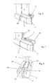
Figures 1 and 2 show astator 1 comprising a plurality of steel sheets slightly insulated from one another. Thestator 1 has a substantial cylindrical shape and defines a stator bore 2. - The
stator 1 has anannular part 3 from whichfingers 4 extend. Thefingers 4 defineslots 5 for thestator conductors 6. - The bore 2 has a substantially cylindrical
central part 7 andconical end parts 8. Theconical end parts 8 are step conical end parts (i.e. the conical surface has steps) because of the laminated structure of the stator). - At the ends of the
stator 1press plates 9 are provided. - Each
press plate 9 has a substantiallyannular part 10 resting on theannular part 3 of thestator 1, andfingers 11 extending from theannular part 10 and resting on thefingers 4 of thestator 1. - During manufacturing or more often during maintenance operations the surface of' the stator bore 2 could be damaged.
- For example during maintenance operation it is often required extraction of the rotor from the stator bore 2; this is done by sliding the rotor (connected to supports) out of the stator bore 2. If during extraction the rotor contacts the stator (for example it falls from a support) it can damage the stator. In other examples, the stator could be damaged during maintenance operation in case a tool falls within the stator bore 2.
- In these cases, when the damage is at the
end parts 8 of thestator 1, the method of the disclosure can be implemented. - Before the method is implemented the whole stator can be checked, in order to find the stator zones that must be repaired.
- Thus a part of the press plate 9 (typically the
finger 11 or a portion thereof) is preferably removed. - Then the damaged end parts of the
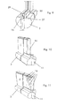
stator 1 are repaired by providing thestator 1 with a seat 15 (figures 5 and9 ) for at least an insert, removing the damaged part of the stator (figures 6 and 7 ), and connecting at least aninsert 16 replacing the damaged part of the stator to the seat 15 (figures 10 through 12 ), and then fixing the insert 16 (figure 14 through 16 ). - Providing the
seat 15 includes drilling a hole in the stator 1 (figure 5 ); when drilling adrilling template 18 can be used to guide thedrill 19 and guarantee precision. For the same reason (i.e. precision) the drilling machine can be fixed to the stator when drilling. - Drilling is preferably carried out at a
finger 4. - After drilling the
drilling template 18 is removed and asaw template 20 is connected to the stator 1 (at the position that was drilled,figure 6 ). - Removing the damaged part of the
stator 1 includes opening theseat 15 towards the stator bore 2 (figures 6, 7 ). This can be done using asaw 21 and thesow template 20 to cut thefingers 4 for the length required.Figure 7 shows thesaw 21 at the end of the cut, when it faces aspacer 22 defining cooling channels for the stator. - After sawing the
saw template 20 is removed and a grinding ormilling template 24 is connected to thestator 1, at the position that was sawn (figure 8 ). - With the help of the grinding or
milling template 24 and a grinding or milling tool 25 (the milling tool is shown infigure 8 ) theseat side borders 18 delimiting theseat 15 from the stator bore 2 are shaped. - Shaping includes making the
seat borders 18 substantially radial and preferably removing the sharp angles (figure 8 ). - Then possible burs are removed, for example by milling or acid methods and flux text are carried out, to control the insulation between adjacent steel sheets and control that the whole damaged part has been removed.
- Thus
insulation 27 is applied into the seat 15 (figure 9 ); this is done before theinsert 16 is connected to theseat 15. For example an insulating resin can be provided into theseat 15. - Then the
inserts 16 are connected to theseat 15. - The
inserts 16 are preferably made of a plurality of steel sheet slightly insulated from one another (i.e. they have a laminated structure like the stator); the steel sheets of theinserts 16 can be the same as (i.e. can have the same geometrical and/or electrical and/or mechanical and/or thermal features) or can be different from the sheets used to manufacture thestator 1. The laminated structure of theinsert 16 helps damping of the magnetic flux at the stepped part of the stator and preventing overheating that could occur if theinsert 16 is made of an insulating material. - Once the
inserts 16 are connected to the seat 15 (figures 10-12 ), they are aligned to thefingers 4 of thestator 1 before they are fixed to thestator 1. - Fixing the
inserts 16 includes providingwedges 28 betweenexternal borders 29 of theseat 15 and theinserts 16. As shown thewedges 28 can have dimensions larger than the final required dimensions (figure 13 ) and can be cut to meet the required dimensions (figure 14 ). - Then an
insulating sheet 31 resting on thelast insert 16 is provided and the removed part of the press plate (for example the finger 11) is reconnected to the press plate 9 (for example it is welded at 32). - Then a
wedge 33 is provided between thelast insert 16 and the reconnected part (for example finger 11) of thepress plate 9. - The
stator 1 after repair has at one or both of its end parts one ormore seats 15 for at least aninsert 16, and theinsert 16 within theseat 15. - Naturally the features described may be independently provided from one another.
- In practice the materials used and the dimensions can be chosen at will according to requirements and to the state of the art.
-
- 1
- stator
- 2
- stator bore
- 3
- annular part
- 4
- fingers
- 5
- slots
- 6
- conductor
- 7
- central part
- 8
- conical end part
- 9
- press plate
- 10
- annular part
- 11
- fingers
- 15
- seat
- 16
- insert
- 18
- drilling template
- 19
- drill
- 20
- saw template
- 21
- saw
- 22
- spacer
- 24
- grinding template
- 25
- grinding tool
- 27
- insulation
- 28
- wedge
- 29
- external border
- 31
- insulating sheet
- 32
- weld
- 33
- wedge
Claims (14)
- A method for repairing a stator (1) having a damaged end part, characterised by
providing the stator (1) with a seat (15) removing the damaged part of the stator (1), connecting at least an insert (16) replacing the damaged part of the stator (1) to the seat (15) fixing the insert (16). - The method of claim 1, characterised in that providing the seat (15) includes drilling a hole in the stator (1).
- The method of claim 1, characterised in that the stator (1) has a stator bore (2), wherein removing the damaged part of the stator (1) includes opening the seat (15) towards the stator bore (2).
- The method of claim 3, characterised by shaping seat side borders (18) delimiting the seat (15) from the stator bore (2).
- The method of claim 4, characterised in that shaping includes making the seat side borders (18) substantially radial.
- The method of claim 1, characterised in that the stator (1) has an annular structure with fingers (4) defining slots (5) for housing stator conductors (35), wherein removing the damaged part of the stator (1) includes cutting at least a part of at least a finger (4).
- The method of claim 1, characterised by applying insulation into the seat (14) before connecting the insert (16) to it.
- The method of claim 1, characterised by aligning the insert (16) to the fingers (4) of the stator (1) before fixing it to the stator (1).
- The method of claim 1, characterised in that fixing the insert (16) includes providing at least a wedge (28) between external borders (29) of the seat (15) and the insert (16).
- The method of claim 1, characterised in that removing the damaged part of the stator (1) includes removing a part of the press plate (9), and fixing the insert (16) includes reconnecting the removed part of the press plate (9).
- The method of claim 10, characterised in that fixing the insert (16) includes providing at least a wedge (33) between the insert (16) and the reconnected part of the press plate (9).
- The method of claim 1, characterised in that the insert (16) includes a plurality of sheets insulated from one another.
- A stator (1), characterised by having at at least one of its end parts (8)
at least a seat (15) for at least an insert (16), and
an insert (16) within the seat (15). - The stator (1) of claim 13, characterised in that the insert (16) includes a plurality of sheets insulated from one another.
Priority Applications (8)
| Application Number | Priority Date | Filing Date | Title |
|---|---|---|---|
| EP12290097.0A EP2642645A1 (en) | 2012-03-20 | 2012-03-20 | Method for repairing a stator |
| CA2865821A CA2865821C (en) | 2012-03-20 | 2013-03-19 | Method for repairing a stator |
| RU2014141894/07A RU2604661C2 (en) | 2012-03-20 | 2013-03-19 | Method of repairing stator |
| EP13713384.9A EP2828957B1 (en) | 2012-03-20 | 2013-03-19 | Method for repairing a stator |
| PCT/EP2013/055717 WO2013139801A1 (en) | 2012-03-20 | 2013-03-19 | Method for repairing a stator |
| CN201380015573.5A CN104205586B (en) | 2012-03-20 | 2013-03-19 | Method for repairing stator |
| IN7190DEN2014 IN2014DN07190A (en) | 2012-03-20 | 2014-08-27 | |
| US14/488,607 US9825511B2 (en) | 2012-03-20 | 2014-09-17 | Method for repairing a stator |
Applications Claiming Priority (1)
| Application Number | Priority Date | Filing Date | Title |
|---|---|---|---|
| EP12290097.0A EP2642645A1 (en) | 2012-03-20 | 2012-03-20 | Method for repairing a stator |
Publications (1)
| Publication Number | Publication Date |
|---|---|
| EP2642645A1 true EP2642645A1 (en) | 2013-09-25 |
Family
ID=48044745
Family Applications (2)
| Application Number | Title | Priority Date | Filing Date |
|---|---|---|---|
| EP12290097.0A Withdrawn EP2642645A1 (en) | 2012-03-20 | 2012-03-20 | Method for repairing a stator |
| EP13713384.9A Active EP2828957B1 (en) | 2012-03-20 | 2013-03-19 | Method for repairing a stator |
Family Applications After (1)
| Application Number | Title | Priority Date | Filing Date |
|---|---|---|---|
| EP13713384.9A Active EP2828957B1 (en) | 2012-03-20 | 2013-03-19 | Method for repairing a stator |
Country Status (7)
| Country | Link |
|---|---|
| US (1) | US9825511B2 (en) |
| EP (2) | EP2642645A1 (en) |
| CN (1) | CN104205586B (en) |
| CA (1) | CA2865821C (en) |
| IN (1) | IN2014DN07190A (en) |
| RU (1) | RU2604661C2 (en) |
| WO (1) | WO2013139801A1 (en) |
Cited By (2)
| Publication number | Priority date | Publication date | Assignee | Title |
|---|---|---|---|---|
| EP2869436A3 (en) * | 2013-10-29 | 2016-08-10 | General Electric Company | Vibration damage repair in dynamoelectric machines |
| WO2023057162A1 (en) * | 2021-10-07 | 2023-04-13 | Siemens Energy Global GmbH & Co. KG | Stabilised end zone regions of a laminated stator core by segments, electrical machine and method of production or repair |
Families Citing this family (3)
| Publication number | Priority date | Publication date | Assignee | Title |
|---|---|---|---|---|
| CN104201830B (en) * | 2014-07-23 | 2017-02-15 | 南车戚墅堰机车有限公司 | Main and auxiliary generator overhauling process |
| US10297162B2 (en) * | 2016-12-28 | 2019-05-21 | Honeywell International Inc. | System and method to activate avionics functions remotely |
| US10868456B2 (en) * | 2018-05-31 | 2020-12-15 | Siemens Energy, Inc. | False tooth assembly for generator stator core |
Citations (2)
| Publication number | Priority date | Publication date | Assignee | Title |
|---|---|---|---|---|
| EP0913912A1 (en) * | 1997-10-30 | 1999-05-06 | ABBPATENT GmbH | Method of repairing packets of laminations of an electrical machine |
| US20070169334A1 (en) * | 2005-12-28 | 2007-07-26 | Koji Matsuyama | Method for removing a crack in an electromechanical rotor, electromechanical rotor and rotary electrical machine |
Family Cites Families (10)
| Publication number | Priority date | Publication date | Assignee | Title |
|---|---|---|---|---|
| US4258281A (en) * | 1979-08-17 | 1981-03-24 | Westinghouse Electric Corp. | Laminated flux shunt for dynamoelectric machine stator |
| US4425521A (en) * | 1982-06-03 | 1984-01-10 | General Electric Company | Magnetic slot wedge with low average permeability and high mechanical strength |
| SU1185504A1 (en) * | 1983-03-02 | 1985-10-15 | Центральное Конструкторское Бюро Главэнергоремонта | Method of assembling magnetic circuit of stator of electric machine |
| CA1323650C (en) * | 1985-11-12 | 1993-10-26 | Franklin Lee Forbes | Electrically commutated motor having an edgewise wound yoke |
| SU1511810A1 (en) * | 1987-05-26 | 1989-09-30 | Ленинградское Электромашиностроительное Объединение "Электросила" Им.С.М.Кирова | Method of repairing laminated stator core of high-power electric machine |
| US5258681A (en) * | 1990-06-29 | 1993-11-02 | Kabushiki Kaisha Toshiba | Magnetic slot wedges for dynamo-electric machines |
| US5174011A (en) * | 1991-03-27 | 1992-12-29 | Klaus Weigelt | Method for preparing the rotor of a turbogenerator |
| US20050172485A1 (en) * | 2004-02-10 | 2005-08-11 | Ramsay Mussen | Method of repair for cast article |
| US7271512B2 (en) * | 2004-02-26 | 2007-09-18 | Lg Electronics Inc. | Stator of outer rotor type motor for drum type washer |
| US20090235516A1 (en) * | 2008-03-19 | 2009-09-24 | Siemens Energy, Inc. | Method of Servicing a Power Generator |
-
2012
- 2012-03-20 EP EP12290097.0A patent/EP2642645A1/en not_active Withdrawn
-
2013
- 2013-03-19 EP EP13713384.9A patent/EP2828957B1/en active Active
- 2013-03-19 WO PCT/EP2013/055717 patent/WO2013139801A1/en active Application Filing
- 2013-03-19 RU RU2014141894/07A patent/RU2604661C2/en active
- 2013-03-19 CN CN201380015573.5A patent/CN104205586B/en active Active
- 2013-03-19 CA CA2865821A patent/CA2865821C/en active Active
-
2014
- 2014-08-27 IN IN7190DEN2014 patent/IN2014DN07190A/en unknown
- 2014-09-17 US US14/488,607 patent/US9825511B2/en active Active
Patent Citations (2)
| Publication number | Priority date | Publication date | Assignee | Title |
|---|---|---|---|---|
| EP0913912A1 (en) * | 1997-10-30 | 1999-05-06 | ABBPATENT GmbH | Method of repairing packets of laminations of an electrical machine |
| US20070169334A1 (en) * | 2005-12-28 | 2007-07-26 | Koji Matsuyama | Method for removing a crack in an electromechanical rotor, electromechanical rotor and rotary electrical machine |
Cited By (3)
| Publication number | Priority date | Publication date | Assignee | Title |
|---|---|---|---|---|
| EP2869436A3 (en) * | 2013-10-29 | 2016-08-10 | General Electric Company | Vibration damage repair in dynamoelectric machines |
| US9508470B2 (en) | 2013-10-29 | 2016-11-29 | General Electric Company | Vibration damage repair in dynamoelectric machines |
| WO2023057162A1 (en) * | 2021-10-07 | 2023-04-13 | Siemens Energy Global GmbH & Co. KG | Stabilised end zone regions of a laminated stator core by segments, electrical machine and method of production or repair |
Also Published As
| Publication number | Publication date |
|---|---|
| EP2828957B1 (en) | 2018-05-16 |
| CN104205586A (en) | 2014-12-10 |
| RU2604661C2 (en) | 2016-12-10 |
| US20150001986A1 (en) | 2015-01-01 |
| WO2013139801A1 (en) | 2013-09-26 |
| CA2865821A1 (en) | 2013-09-26 |
| IN2014DN07190A (en) | 2015-04-24 |
| US9825511B2 (en) | 2017-11-21 |
| CA2865821C (en) | 2020-03-10 |
| RU2014141894A (en) | 2016-05-10 |
| CN104205586B (en) | 2018-04-06 |
| EP2828957A1 (en) | 2015-01-28 |
Similar Documents
| Publication | Publication Date | Title |
|---|---|---|
| US9825511B2 (en) | Method for repairing a stator | |
| US8443509B1 (en) | Preparing bar-wound stator conductors for electrical interconnection | |
| US6849972B1 (en) | Generator rotor fretting fatigue crack repair | |
| US8959754B2 (en) | Method and apparatus for removing a coil from a slot of a dynamoelectric machine | |
| EP3785354B1 (en) | False tooth assembly for generator stator core | |
| EP2642646B1 (en) | Method for manufacturing a stator | |
| JP2007181381A (en) | Method for repairing crack of rotary electric machine rotor, method for preventing development of crack in rotary electric machine rotor, rotary electric machine rotor and rotary electric machine | |
| EP2870683B1 (en) | Method for removing bars or coils from slots of an electric machine | |
| EP2831983B1 (en) | Electric machine and assembling method | |
| US20080278009A1 (en) | Method and apparatus for generator rotor tooth repair | |
| EP2642644B1 (en) | Method for repairing a rotor and rotor | |
| JP5935378B2 (en) | Magnet piece manufacturing apparatus constituting field pole magnet body | |
| EP2642647A1 (en) | Stator and method for manufacturing a stator | |
| EP2755307A1 (en) | Method and device for manufacturing a laminated stator core | |
| CN106059209A (en) | Generator rotor fretting fatigue crack repair method | |
| Norry et al. | Influence of Manufacturing Faults on Squirrel Cage Induction Motor | |
| CN104205587B (en) | Method and rotor for repairing rotor | |
| US20200251950A1 (en) | Winding of a generator of a wind power installation, and method for connecting flat ribbon conductors | |
| WO2014068356A1 (en) | Grooved wedge for rotor |
Legal Events
| Date | Code | Title | Description |
|---|---|---|---|
| PUAI | Public reference made under article 153(3) epc to a published international application that has entered the european phase |
Free format text: ORIGINAL CODE: 0009012 |
|
| AK | Designated contracting states |
Kind code of ref document: A1 Designated state(s): AL AT BE BG CH CY CZ DE DK EE ES FI FR GB GR HR HU IE IS IT LI LT LU LV MC MK MT NL NO PL PT RO RS SE SI SK SM TR |
|
| AX | Request for extension of the european patent |
Extension state: BA ME |
|
| STAA | Information on the status of an ep patent application or granted ep patent |
Free format text: STATUS: THE APPLICATION IS DEEMED TO BE WITHDRAWN |
|
| 18D | Application deemed to be withdrawn |
Effective date: 20140326 |