EP2868878B1 - Oil separator - Google Patents
Oil separator Download PDFInfo
- Publication number
- EP2868878B1 EP2868878B1 EP13813825.0A EP13813825A EP2868878B1 EP 2868878 B1 EP2868878 B1 EP 2868878B1 EP 13813825 A EP13813825 A EP 13813825A EP 2868878 B1 EP2868878 B1 EP 2868878B1
- Authority
- EP
- European Patent Office
- Prior art keywords
- oil separator
- oil
- gas
- blowby gas
- distribution
- Prior art date
- Legal status (The legal status is an assumption and is not a legal conclusion. Google has not performed a legal analysis and makes no representation as to the accuracy of the status listed.)
- Not-in-force
Links
- 238000007599 discharging Methods 0.000 claims description 46
- 239000003921 oil Substances 0.000 description 250
- 239000003595 mist Substances 0.000 description 57
- 239000002245 particle Substances 0.000 description 10
- 238000009413 insulation Methods 0.000 description 9
- JTJMJGYZQZDUJJ-UHFFFAOYSA-N phencyclidine Chemical class C1CCCCN1C1(C=2C=CC=CC=2)CCCCC1 JTJMJGYZQZDUJJ-UHFFFAOYSA-N 0.000 description 8
- 238000002485 combustion reaction Methods 0.000 description 4
- 239000000203 mixture Substances 0.000 description 4
- 230000008014 freezing Effects 0.000 description 3
- 238000007710 freezing Methods 0.000 description 3
- 238000000926 separation method Methods 0.000 description 3
- 238000010257 thawing Methods 0.000 description 3
- 239000007788 liquid Substances 0.000 description 2
- 239000000314 lubricant Substances 0.000 description 1
- 239000010705 motor oil Substances 0.000 description 1
- 239000011347 resin Substances 0.000 description 1
- 229920005989 resin Polymers 0.000 description 1
- 238000000638 solvent extraction Methods 0.000 description 1
- 238000009423 ventilation Methods 0.000 description 1
- 238000003466 welding Methods 0.000 description 1
Images


Classifications
-
- B—PERFORMING OPERATIONS; TRANSPORTING
- B01—PHYSICAL OR CHEMICAL PROCESSES OR APPARATUS IN GENERAL
- B01D—SEPARATION
- B01D35/00—Filtering devices having features not specifically covered by groups B01D24/00 - B01D33/00, or for applications not specifically covered by groups B01D24/00 - B01D33/00; Auxiliary devices for filtration; Filter housing constructions
- B01D35/005—Filters specially adapted for use in internal-combustion engine lubrication or fuel systems
-
- F—MECHANICAL ENGINEERING; LIGHTING; HEATING; WEAPONS; BLASTING
- F01—MACHINES OR ENGINES IN GENERAL; ENGINE PLANTS IN GENERAL; STEAM ENGINES
- F01M—LUBRICATING OF MACHINES OR ENGINES IN GENERAL; LUBRICATING INTERNAL COMBUSTION ENGINES; CRANKCASE VENTILATING
- F01M13/00—Crankcase ventilating or breathing
- F01M13/04—Crankcase ventilating or breathing having means for purifying air before leaving crankcase, e.g. removing oil
- F01M13/0405—Crankcase ventilating or breathing having means for purifying air before leaving crankcase, e.g. removing oil arranged in covering members apertures, e.g. caps
-
- B—PERFORMING OPERATIONS; TRANSPORTING
- B01—PHYSICAL OR CHEMICAL PROCESSES OR APPARATUS IN GENERAL
- B01D—SEPARATION
- B01D45/00—Separating dispersed particles from gases or vapours by gravity, inertia, or centrifugal forces
- B01D45/12—Separating dispersed particles from gases or vapours by gravity, inertia, or centrifugal forces by centrifugal forces
- B01D45/16—Separating dispersed particles from gases or vapours by gravity, inertia, or centrifugal forces by centrifugal forces generated by the winding course of the gas stream, the centrifugal forces being generated solely or partly by mechanical means, e.g. fixed swirl vanes
-
- B—PERFORMING OPERATIONS; TRANSPORTING
- B04—CENTRIFUGAL APPARATUS OR MACHINES FOR CARRYING-OUT PHYSICAL OR CHEMICAL PROCESSES
- B04C—APPARATUS USING FREE VORTEX FLOW, e.g. CYCLONES
- B04C5/00—Apparatus in which the axial direction of the vortex is reversed
- B04C5/02—Construction of inlets by which the vortex flow is generated, e.g. tangential admission, the fluid flow being forced to follow a downward path by spirally wound bulkheads, or with slightly downwardly-directed tangential admission
- B04C5/04—Tangential inlets
-
- B—PERFORMING OPERATIONS; TRANSPORTING
- B04—CENTRIFUGAL APPARATUS OR MACHINES FOR CARRYING-OUT PHYSICAL OR CHEMICAL PROCESSES
- B04C—APPARATUS USING FREE VORTEX FLOW, e.g. CYCLONES
- B04C5/00—Apparatus in which the axial direction of the vortex is reversed
- B04C5/24—Multiple arrangement thereof
- B04C5/28—Multiple arrangement thereof for parallel flow
-
- F—MECHANICAL ENGINEERING; LIGHTING; HEATING; WEAPONS; BLASTING
- F01—MACHINES OR ENGINES IN GENERAL; ENGINE PLANTS IN GENERAL; STEAM ENGINES
- F01M—LUBRICATING OF MACHINES OR ENGINES IN GENERAL; LUBRICATING INTERNAL COMBUSTION ENGINES; CRANKCASE VENTILATING
- F01M13/00—Crankcase ventilating or breathing
- F01M13/04—Crankcase ventilating or breathing having means for purifying air before leaving crankcase, e.g. removing oil
- F01M13/0416—Crankcase ventilating or breathing having means for purifying air before leaving crankcase, e.g. removing oil arranged in valve-covers
-
- F—MECHANICAL ENGINEERING; LIGHTING; HEATING; WEAPONS; BLASTING
- F01—MACHINES OR ENGINES IN GENERAL; ENGINE PLANTS IN GENERAL; STEAM ENGINES
- F01M—LUBRICATING OF MACHINES OR ENGINES IN GENERAL; LUBRICATING INTERNAL COMBUSTION ENGINES; CRANKCASE VENTILATING
- F01M13/00—Crankcase ventilating or breathing
- F01M2013/0038—Layout of crankcase breathing systems
- F01M2013/005—Layout of crankcase breathing systems having one or more deoilers
- F01M2013/0061—Layout of crankcase breathing systems having one or more deoilers having a plurality of deoilers
- F01M2013/0066—Layout of crankcase breathing systems having one or more deoilers having a plurality of deoilers in parallel
-
- F—MECHANICAL ENGINEERING; LIGHTING; HEATING; WEAPONS; BLASTING
- F01—MACHINES OR ENGINES IN GENERAL; ENGINE PLANTS IN GENERAL; STEAM ENGINES
- F01M—LUBRICATING OF MACHINES OR ENGINES IN GENERAL; LUBRICATING INTERNAL COMBUSTION ENGINES; CRANKCASE VENTILATING
- F01M13/00—Crankcase ventilating or breathing
- F01M13/04—Crankcase ventilating or breathing having means for purifying air before leaving crankcase, e.g. removing oil
- F01M2013/0422—Separating oil and gas with a centrifuge device
- F01M2013/0427—Separating oil and gas with a centrifuge device the centrifuge device having no rotating part, e.g. cyclone
Definitions
- the present invention relates to an oil separator configured to separate oil mist from blowby gas.
- An engine obtains power by rotating a crankshaft with combustion of mixture gas in a combustion chamber.
- not all of an amount of mixture gas introduced to the combustion chamber is combusted.
- a portion of the mixture gas leaks into a crankcase via a gap present between a piston and a cylinder.
- This leaked gas is called blowby gas.
- blowby gas It is legally prohibited, in particular in Japan, to discharge blowby gas, which is un-combusted gas, directly into the atmosphere as emission gas. For this reason, blowby gas is returned to an intake port via a PVC (Positive Crankcase Ventilation) channel to be mixed with newly introduced mixture gas for subsequent combustion together and eventual emission into the atmosphere.
- PVC Physical Crankcase Ventilation
- Blowby gas contains therein a certain amount of lubricant oil such as engine oil in the form of oil mist. If blowby gas containing oil mist is returned to the intake port, the oil will adhere to the PCV channel and/or periphery of the intake port undesirably. Then, for the purpose of collecting oil mist present in blowby gas, an oil separator is provided inside a cylinder head cover or in midway of the PCV channel.
- Patent Document 1 discloses an oil separator using a plurality of cyclones. With this oil separator, blowby gas entering via a gas introducing opening is introduced through a rectifying chamber to the multiple cyclones which are disposed side by side in series. Due to a centrifugal force by a swirling stream generated inside the cyclone, oil mist present in the blowby gas is flocculated and collected. Further oil separators are known from Patent Documents 2 to 9.
- Blowby gas contains oil mist of various particle sizes.
- the blowby gas introducing opening is disposed at an end portion, so distances from this gas introducing opening to the respective cyclones disposed side by side in series differ from each other.
- oil mist having large particles sizes tend to be present mostly in the vicinity of the gas introducing opening, and the particle sizes of the oil mist become smaller and smaller away from the gas introducing opening. This is because oil mist having large particle sizes have large masses. Therefore, a cyclone disposed near the gas introducing opening will collect much of the oil mist having large particle sizes, and the particle sizes of the oil mist collected by the cyclones become smaller and smaller as the cyclones are located away from the gas introducing opening. Due to the particle size difference of the oil mist collected by the respective cyclones, oil-mist collection efficiencies of the respective cyclones also differ from each other, so that efficient oil mist collection by the oil separator as a whole is not possible.
- an object of the present invention is to provide an oil separator capable of efficient operation as a whole, regardless of particle size differences of respective multiple oil separator units (cyclones), through uniform collection of oil mist contained in blowby gas by effective separation of the oil mist.
- an oil separator is configured according to claim 1.
- At least one of a channel cross section area or a channel length of the distribution channel is same for all the respective distribution channels.
- the amounts of blowby gas introduced to the oil separator units in a unit time period can be made equal, so that all the oil separator units can achieve substantially same level of oil mist collection efficiency.
- the oil separator as a whole can operate in an efficient manner for oil mist collection.
- At least one of a flow rate and a velocity of the blowby gas flowing in the each distribution channel is same.
- the amounts of blowby gas introduced to the oil separator units in a unit time period can be made equal, so that all the oil separator units can achieve substantially same level of oil mist collection efficiency.
- the oil separator as a whole can operate in an efficient manner for oil mist collection.
- the oil separator further comprises a gas discharging hole discharging blowby gas exiting the oil separator units to the outside; and the gas discharging hole and the gas introducing hole are disposed on a same axis.
- a wall face of the distribution chamber present in the flowing direction of blowby gas introduced through the introducing hole to the distribution chamber includes a guide configured to guide the blowby gas to the respective distribution channel.
- the blowby gas introduced to the distribution chamber can be guided by the guide to the respective distribution channels equally.
- all the oil separator units can achieve substantially same level of oil mist collection efficiency.
- the oil separator as a whole can operate in an efficient manner for oil mist collection.
- the oil separator further comprises a first lid portion surrounding and covering therein the oil separator units, the distribution chamber, the introducing hole and the distribution channels, and a second lid portion surrounding and covering therein the first lid portion, the first lid portion and the second lid portion together forming at least a portion of a lateral face portion as a double-layered structure.
- the portion formed as the double-layered structure comprises a sealed space.
- a space into which the oil from the oil separator units is discharged is formed on the inner side of the double-layered structure.
- an oil separator comprises:
- the oil separator units, the distribution chamber, the introducing hole and the distribution channels are frozen, speedy thawing is possible with the blowby gas, thus allowing the oil separator to operation speedily to its appropriate state.
- all the oil separator units can achieve substantially same level of oil mist collection efficiency.
- the oil separator as a whole can operate in an efficient manner for oil mist collection.
- the portion formed as the double-layered structure comprises a sealed space.
- a space into which the oil is discharged from the oil separator units is formed on the inner side of the double-layered structure.
- a closed space is formed between the portion formed as the double-layered structure and the space into which the oil is discharged from the oil separator units.
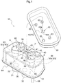
- Fig. 1 shows an exploded perspective view showing an outer appearance of an oil separator 10 according to this embodiment.
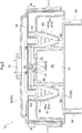
- Fig. 2 shows a vertical section showing a configuration of the oil separator 10.
- Fig. 3 shows a section taken along a line III-III in Fig. 2 .
- Fi. 4 shows a section taken along a line IV-IV in Fig. 3 .
- the oil separator 10 is mounted inside a head cover (not shown) of an engine of a vehicle. This oil separator 10 is formed of a resin.
- the oil separator 10 includes a housing 20 constituting an outer appearance of the separator, a first reservoir chamber 30 formed inside the housing 20, gas introducing pipes 32, 32, a distribution chamber 40, distribution channels 50, 50, 50, 50, oil separator units 60, 60, 60, 60, an oil discharging pipe 64, a second reservoir chamber 90 and an gas discharging hole 81.
- the first reservoir chamber 30 is a space partitioned by a partitioning plate and having a shape of a triangular prism.
- a portion of a bottom plate 21 constituting the housing 20 forms a bottom face 31 of the first reservoir chamber 30.
- the bottom face 31 integrally forms the two gas introducing pipes 32, 32.
- Each gas introducing pipe 32 has a hole defined in the bottom face 31 and a tubular wall having a tubular bore continuous with the above hole and projecting toward the outside of the separator 10 from the bottom plate 21.
- the gas introducing pipe 32 is connected to an unillustrated gas introducing channel.
- An upper face 33 of the first reservoir chamber 30 defines a circular introducing hole 41.
- a distribution chamber 40 which is a cylindrical space.
- the first reservoir chamber 30 and the distribution chamber 40 are communicated to each other via the introducing hole 41.
- the inside diameter of the distribution chamber 40 is same as the inside diameter of the introducing hole 41 and the capacity of the distribution chamber 40 is much smaller than the capacity of the first reservoir chamber 30.
- the distribution channels 50, 50, 50, 50 are formed to extend straight toward the radially outer side and in parallel with the bottom face 31.
- the distribution chamber 40 and the distribution channels 50 are communicated to each other.
- the four distribution channels 50, 50, 50, 50 have a same channel cross section area in a direction perpendicular to flowing directions of blowby gas and have a same channel length also.
- a first lid plate 70 is attached on top of the distribution chamber 40.
- the first lid plate 70 is gaplessly connected by bonding, welding, etc. to an upper edge A of the distribution chamber 40, the distribution channels 50, 50, 50, 50, and the oil separator units 60, 60, 60, 60 shown in Fig. 1 .
- An upper face 42 (a portion of the first lid plate 70) of the distribution chamber 40 includes a guide 43 projecting from the upper face 42 toward the distribution chamber 40.
- This guide 43 has a shape of a quadrangular pyramid having a bottom face which comes into contact with the upper face 42. As shown in Fig. 3 , four lateral faces 43a, 43a, 43a, 43a of the guide 43 are formed to extend perpendicular to the flowing directions of blowby gas inside the four respective distribution channels 50, 50, 50, 50.
- each oil separator unit 60 is connected to the distribution channel 50 corresponding thereto.
- the each oil separator unit 60 includes a main body portion 61, an oil discharging portion 62 and a gas discharging portion 63.
- the four oil separator units 60, 60, 60, 60 all have a same size, with respective axes thereof being parallel with each other and also perpendicular to the flowing directions of the blowby gas in the respective distribution channels 50. Further, as shown in Fig.
- the distribution channels 50, 50, 50, 50 and the oil separator units 60, 60, 60, 60 are disposed in line-symmetry relative to a plane X and a plane Y which are perpendicular to each other and extend through the axis of the introducing hole 41 (distribution chamber 40).
- the main body portion 61 has a cylinder portion 61a having a cylindrical shape and a cone portion 61 b coaxial with the cylinder portion 61 a and continuous from the lower end of the cylinder portion 61a and progressively reduced in its diameter downwards.
- Each distribution channel 50 and each oil separator unit 60 corresponding thereto are disposed such that the distribution channel 50 extends along a tangential direction of the inner circumferential face of the cylinder portion 61 a.
- an opening is formed as the oil discharging portion 62.
- the two oil separator units 60, 60 opposed to each other relative to the plane X are disposed near each other whereas the oil separator units 60, 60 opposed to each other relative to the plane Y are disposed away from each other.
- this arrangement it is possible to reduce the thickness of the oil separator 10 in the direction perpendicular to the plane X.
- the oil discharging pipes 64, 64 are formed at two positions for discharging oil mist to the outside of the oil separator 10. As shown by broken-line arrows in Fig. 3 , in the bottom plate 21, a gentle downward slope extending from the position intersecting the axes of the two oil separator units 60, 60 toward the oil discharging pipe 64 provided at one position is formed for the respective oil discharging pipe 64.
- the gas discharging portion 63 is formed integral in the first lid plate 70, and includes a hole formed in the first lid plate 70 and a cylindrical wall having a cylindrical bore continuous with the above hole and projecting from the first lid plate 70 toward the oil separator unit 60.
- the lower end of the gas discharging portion 63 is present inside the cylinder portion 61a and the axis of the gas discharging portion 63 constitutes the same axis of the cylinder portion 61a.
- the upper end of the gas discharging portion 63 is opened to the outside of the first lid plate 70.
- the four gas discharging portions 63 all are of a same size.
- a second lid plate 80 forming a part of the housing 20 is disposed.
- the first lid plate 70 and the second lid plate 80 together form the second reservoir chamber 90.
- the second lid plate 80 defines a gas discharging hole 81 for discharging blowby gas reserved in the second reservoir chamber 90 to the outside of the oil separator 10.
- the blowby gas reserved in the second reservoir chamber 90 is blowby gas from which oil mist has been separated by the oil separator unit 60. Therefore, this blowby gas will be referred to simply as "gas" hereinafter.
- the axis of the gas discharging hole 81 is same as the axis of the distribution chamber 40. To this gas discharging hole 81, an unillustrated gas discharging channel is connected.
- the other end of the gas discharging channel is connected to an intake port. Blowby gas is sucked by a negative pressure generated by air flowing through the intake port to flow the inside of the oil separator 10.
- blowby gas drawn out of the crankcase and flown through the gas introducing channel flows into the first reservoir chamber 30 via the gas introducing pipe 32.
- the introduced blowby gas is reserved temporarily inside the first reservoir chamber 30.
- the blowby gas introduced from the first reservoir chamber 30 into the distribution chamber 40 collides the lateral faces 43a of the guide 43, thus being distributed equally in the four directions to flow into the distribution channels 50, 50, 50, 50.
- the blowby gas flown past the distribution channels 50, 50, 50, 50 will flow into the oil separator units 60, 60, 60, 60 and then flow along the inner circumferential faces of the cylinder portions 61a, 61a, 61a, 61a.
- the blowby gas will swirl along the inner circumferential face of the cylinder portion 61 a, thus forming a swirling stream falling toward the cone portion 61 b.
- a centrifugal force is generated in the blowby gas, whereby oil mist contained in the blowby gas will be caused to collide the inner circumferential face of the cylinder portion 61a or the cone portion 61 b and will adhere thereto. With this, the oil mist is separated and collected from the blowby gas.
- the swirling directions of the swirling streams inside the respective oil separator units 60 are also symmetric relative to the plane X and the plane Y.
- the oil mist adhered to the inner circumferential face of the cylinder portion 61 a or the cone portion 61 b will flocculate while flowing down along the wall face of the cone portion 61 b and then will drop onto the bottom plate 21 through the oil discharging portion 62. As shown by the broken-line arrows in Fig. 3 and Fig. 2 , the dropped oil mist will flow down along the slope of the bottom plate 21 and pass the inner channel of the oil discharge discharging pipe 64 and eventually be discharged to the outside of the oil separator 10 and returned to the unillustrated oil pan.
- the gas will flow through the gas discharging portion 63 and flow into the second reservoir chamber 90. Thereafter, the gas will be discharged through the gas discharging hole 81 and flow through the gas discharge channel and be returned to the intake port.
- the oil separator 10 is configured such that the distribution channels 50, 50, 50, 50 and the oil separator units 60, 60, 60, 60 are arranged radially around the center constituted by the distribution chamber 40 for distributing blowby gas and also that the gas discharging hole 81 is disposed coaxial with the distribution chamber 40. Moreover, as described above, the four distribution channels 50, 50, 50, 50 all have a same channel cross section area as determined perpendicularly to the blowby gas flowing direction as well as a same channel length. Further, the four oil separator units 60, 60, 60, 60 including the gas discharge portions 63 are of a same size.
- the blowby gas with containing oil mist of all particle sizes therein will flow into the four oil separator units 60, 60, 60, 60 respectively in a uniform manner.
- the each oil separator unit 60 can collect equally oil mist present in the blowby gas, regardless of the sizes of the oil mist.
- the four oil separator units 60, 60, 60, 60 can achieve substantially equal oil mist collecting efficiency, so that the oil separator 10 as a whole can be operated in an efficient manner for oil mist collection.
- the gas discharging hole 81 and the distribution chamber 40 are disposed coaxially, so that the channel lengths from the respective gas discharging portions 63 via the second reservoir chamber 90 to the gas discharging hole 81 are also equal. Accordingly, the gas can be discharged equally from the respective oil separator units 60. Consequently, the four oil separator units 60, 60, 60, 60 can achieve substantially equal gas discharging efficiency, so that the oil separator 10 as a whole can operate in an efficient manner for gas discharging also.
- the four distribution channels 50, 50, 50, 50 all have a same channel cross section area as determined perpendicularly to the blowby gas flowing direction as well as a same channel length.
- the configuration is not limited thereto. Either only one of the channel cross sections and the channel lengths can be made same.
- the channel cross section areas and the channel lengths of the distribution channels 50 are different, an arrangement can still be made for setting the channel cross section areas and the channel lengths such that the amounts per unit period time of blowby gas flowing into the four oil separator units 60, 60, 60, 60 are rendered equal to each other.
- the channel cross section area of a distribution channel 50 having a longer channel length should be set larger, whereas the channel cross section area of a distribution channel 50 having a shorter channel length should be set smaller.
- the channel cross section areas and the channel lengths of the distribution channels 50 can be set such that the flowing velocities of blowby gas flowing through the four distribution channels 50, 50, 50, 50 may be equal to each other.
- the distribution channels 50, 50, 50, 50 and the oil separator units 60, 60, 60, 60 are disposed symmetric relative to the plane X and the plane Y.
- the configuration is not limited thereto.
- the distribution channels 50, 50, 50, 50 and the oil separator units 60, 60, 60, 60 may be disposed symmetric relative to only one of the plane X and the plane Y.
- Fig. 5 shows a horizontal section showing layouts of distribution channels 50 and oil separator units 60 of an oil separator 10 according to a variation of the first embodiment.
- portions identical to those in the first embodiment will be denoted with the same marks/numerals as the first embodiment and explanations thereof will be omitted.
- four distribution channels 50, 50, 50, 50 are disposed with 90 degrees angular spacing from each other; and also the distribution channels 50 and the oil separator units 60 are arranged such that the swirling direction of swirling streams of blowby gas inside all the oil separator units 60, 60, 60, 60 may be same.
- the rest of the configuration is identical to the first embodiment.
- Fig. 6 shows a vertical section showing a general configuration of an oil separator 10 according to a second embodiment.
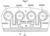
- Fig. 7 shows a section taken along a line VII-VII in Fig. 6 .
- the introducing hole 41 is formed at an end of the housing 20 and also the axes of the four oil separator units 60, 60, 60, 60 are arranged inline on the plane X.
- this embodiment differs from the first embodiment.
- the gas discharging hole 81 is provided at an end of the oil separator 10.
- outer distribution channels 50a, 50a extending from the introducing hole 41 to two outer oil separator units 60a, 60a disposed on the outer side have a channel cross section area perpendicular to the flowing direction and a channel length which are greater respectively than a channel cross section area perpendicular to the flowing direction and a channel length of inner distribution channels 50b, 50b extending to two inner oil separator units 60b, 60b disposed on the inner side.
- the oil separator 10 relating to the present invention can be described as follows.
- the oil separator 10 includes at least one set of cyclone type oil separator units 60 effecting gas-liquid separation of blowby gas, a distribution chamber 40 distributing blowby gas to be introduced to the oil separator units 60, an introducing hole 41 introducing the blowby gas into the distribution chamber 40, distribution channels 50 causing the blowby gas to flow from the distribution chamber 40 to the respective oil separator units 60, a first lid plate 70 (corresponding to "a first lid portion” in the invention) surrounding and covering therein the oil separator units 60, the distribution chamber 40, the introducing hole 41 and the distribution channels 50, and a second lid plate 80 (corresponding to "a second lid portion” in the invention) surrounding and covering therein the first lid portion 70.
- the first lid plate 70 and the second lid plate 80 together form at least a portion of a lateral face portion as a double-layered structure.
- the oil separator units 60, the distribution chamber 40, the introducing hole 41 and the distribution channels 50 are frozen, speedy thawing is possible with the blowby gas, thus allowing the oil separator 10 to operation speedily to its appropriate state.
- all the oil separator units 60 can achieve substantially equal level of oil mist collection efficiency.
- the oil separator 10 as a whole can operate in an efficient manner for oil mist collection.
- the portion formed as the double-layered structure can comprise a sealed space.
- a space into which the oil is discharged from the oil separator units 60 can be formed on the inner side of the double-layered structure.
- a closed space can be formed between the portion formed as the double-layered structure and the space into which the oil is discharged from the oil separator units 60.
- the present invention is applicable to an oil separator configured to separate oil mist from blowby gas.
Description
- The present invention relates to an oil separator configured to separate oil mist from blowby gas.
- An engine obtains power by rotating a crankshaft with combustion of mixture gas in a combustion chamber. However, not all of an amount of mixture gas introduced to the combustion chamber is combusted. A portion of the mixture gas leaks into a crankcase via a gap present between a piston and a cylinder. This leaked gas is called blowby gas. It is legally prohibited, in particular in Japan, to discharge blowby gas, which is un-combusted gas, directly into the atmosphere as emission gas. For this reason, blowby gas is returned to an intake port via a PVC (Positive Crankcase Ventilation) channel to be mixed with newly introduced mixture gas for subsequent combustion together and eventual emission into the atmosphere.
- Blowby gas contains therein a certain amount of lubricant oil such as engine oil in the form of oil mist. If blowby gas containing oil mist is returned to the intake port, the oil will adhere to the PCV channel and/or periphery of the intake port undesirably. Then, for the purpose of collecting oil mist present in blowby gas, an oil separator is provided inside a cylinder head cover or in midway of the PCV channel.
- Patent Document 1 discloses an oil separator using a plurality of cyclones. With this oil separator, blowby gas entering via a gas introducing opening is introduced through a rectifying chamber to the multiple cyclones which are disposed side by side in series. Due to a centrifugal force by a swirling stream generated inside the cyclone, oil mist present in the blowby gas is flocculated and collected.
Further oil separators are known from Patent Documents 2 to 9. -
- Patent Document 1: Japanese Unexamined Patent Application Publication No.
2009-221857 - Patent Document 2:
WO 2004/042202 A1 - Patent Document 3:
JP 2003 528704 A - Patent Document 4:
JP S62 102849 A - Patent Document 5:
DE 202 11 439 U1 - Patent Document 6:
DE 199 12 271 A1 - Patent Document 7:
JP 2009 013941 A - Patent Document 8:
JP 2006 022700 A - Patent Document 9:
JP 2012 036802 A - Blowby gas contains oil mist of various particle sizes. In the case of the oil separator disclosed in Patent Document 1, the blowby gas introducing opening is disposed at an end portion, so distances from this gas introducing opening to the respective cyclones disposed side by side in series differ from each other. Further, oil mist having large particles sizes tend to be present mostly in the vicinity of the gas introducing opening, and the particle sizes of the oil mist become smaller and smaller away from the gas introducing opening. This is because oil mist having large particle sizes have large masses. Therefore, a cyclone disposed near the gas introducing opening will collect much of the oil mist having large particle sizes, and the particle sizes of the oil mist collected by the cyclones become smaller and smaller as the cyclones are located away from the gas introducing opening. Due to the particle size difference of the oil mist collected by the respective cyclones, oil-mist collection efficiencies of the respective cyclones also differ from each other, so that efficient oil mist collection by the oil separator as a whole is not possible.
- In view of the above-described problem, an object of the present invention is to provide an oil separator capable of efficient operation as a whole, regardless of particle size differences of respective multiple oil separator units (cyclones), through uniform collection of oil mist contained in blowby gas by effective separation of the oil mist.
- For accomplishing the above-noted object, according to a characterizing feature of the invention, an oil separator is configured according to claim 1.
- With the above-described characterizing feature, thanks to the symmetric layouts of the distribution channels and the oil separator units, it is possible to cause blowby gas containing oil mist of all of various particles sizes to enter the oil separator units, whereby the amount of blowby gas introduced in a unit time period can be made equal for all of the oil separator units. Consequently, all the oil separator units can provide a substantially equal oil mist collection efficiency, and the oil separator as a whole can operate in an efficient manner for oil mist collection.
- Furthermore, with the above-described arrangement, it is possible also to enhance the heat insulation of the space into which the oil is discharged from the oil separator units. Accordingly, even when this space is frozen, it is possible to bring the oil separator into its appropriate operation speedily. Thus, all the oil separator units can achieve substantially same level of gas discharging efficiency. As a result, the oil separator as a whole can operate in an efficient manner not only for oil mist collection, but also for discharging of the blowby gas.
- In the oil separator having the above-described configuration, preferably, at least one of a channel cross section area or a channel length of the distribution channel is same for all the respective distribution channels.
- With the above-described arrangement, the amounts of blowby gas introduced to the oil separator units in a unit time period can be made equal, so that all the oil separator units can achieve substantially same level of oil mist collection efficiency. As a result, the oil separator as a whole can operate in an efficient manner for oil mist collection.
- In the oil separator having the above-described configuration, preferably, at least one of a flow rate and a velocity of the blowby gas flowing in the each distribution channel is same.
- With the above-described arrangement too, the amounts of blowby gas introduced to the oil separator units in a unit time period can be made equal, so that all the oil separator units can achieve substantially same level of oil mist collection efficiency. As a result, the oil separator as a whole can operate in an efficient manner for oil mist collection.
- In the oil separator having the above-described configuration, preferably, the oil separator further comprises a gas discharging hole discharging blowby gas exiting the oil separator units to the outside; and the gas discharging hole and the gas introducing hole are disposed on a same axis.
- With the above-described arrangement, channel lengths from the respective oil separator units to the gas discharging hole are same also. Accordingly, blowby gas can be discharged equally from the respective oil separator units. Thus, all the oil separator units can achieve substantially same level of oil mist collection efficiency. As a result, the oil separator as a whole can operate in an efficient manner not only for oil mist collection, but also for blowby gas discharging.
- In the oil separator having the above-described configuration, preferably, a wall face of the distribution chamber present in the flowing direction of blowby gas introduced through the introducing hole to the distribution chamber includes a guide configured to guide the blowby gas to the respective distribution channel.
- With the above-described arrangement, the blowby gas introduced to the distribution chamber can be guided by the guide to the respective distribution channels equally. Thus, all the oil separator units can achieve substantially same level of oil mist collection efficiency. As a result, the oil separator as a whole can operate in an efficient manner for oil mist collection.
- In the oil separator having the above-described configuration, preferably, the oil separator further comprises a first lid portion surrounding and covering therein the oil separator units, the distribution chamber, the introducing hole and the distribution channels, and a second lid portion surrounding and covering therein the first lid portion, the first lid portion and the second lid portion together forming at least a portion of a lateral face portion as a double-layered structure.
- With the above-described arrangement, even when there exists a temperature difference between the inner side of the first lid portion and the outer side of the second lid portion, it is possible to alleviate the influence of the temperatures to each other. For this reason, for instance, in case an extremely low temperature exits on the outer side of the second lid portion, thus freezing the inside of the first lid portion, it is possible to restrict drop in the temperature of the blowby gas supplied to the inside of the first lid portion due to the temperature prevailing on the outer side of the second lid portion, so that the inside of the first lid portion can be heated smoothly by the blowby gas. Accordingly, even when the oil separator units, the distribution chamber, the introducing hole and the distribution channels are frozen, speedy thawing is possible with the blowby gas, thus allowing the oil separator to operation speedily to its appropriate state. Thus, all the oil separator units can achieve substantially same level of oil mist collection efficiency. As a result, the oil separator as a whole can operate in an efficient manner for oil mist collection.
- In the oil separator having the above-described configuration, preferably, the portion formed as the double-layered structure comprises a sealed space.
- With the above-described arrangement, it is made possible to further improve the heat insulation between the first lid portion and the second lid portion. Accordingly, even when the respective portions of this space are frozen, it is possible to bring the oil separator into its appropriate operation speedily. As a result, the oil separator as a whole can operate in an efficient manner for oil mist collection.
- In the oil separator having the above-described configuration, preferably, a space into which the oil from the oil separator units is discharged is formed on the inner side of the double-layered structure.
- With the above-described arrangement, it is possible also to enhance the heat insulation of the space into which the oil is discharged from the oil separator units. Accordingly, even when this space is frozen, it is possible to bring the oil separator into its appropriate operation speedily. As a result, the oil separator as a whole can operate in an efficient manner for oil mist collection.
- For accomplishing the above-noted object, according to a further characterizing feature of the present invention, an oil separator comprises:
- at least one set of cyclone type oil separator units effecting gas-liquid separation of blowby gas;
- a distribution chamber distributing blowby gas to be introduced to the oil separator units;
- an introducing hole introducing the blowby gas into the distribution chamber;
- distribution channels causing the blowby gas to flow from the distribution chamber to the respective oil separator units;
- a first lid portion surrounding and covering therein the oil separator units, the distribution chamber, the introducing hole and the distribution channels, and
- a second lid portion surrounding and covering therein the first lid portion;
- the first lid portion and the second lid portion together forming at least a portion of a lateral face portion as a double-layered structure.
- With the above-described arrangement, even when there exists a temperature difference between the inner side of the first lid portion and the outer side of the second lid portion, it is possible to alleviate the influence of the temperatures to each other. For this reason, for instance, in case an extremely low temperature exits on the outer side of the second lid portion, thus freezing the inside of the first lid portion, it is possible to restrict drop in the temperature of the blowby gas supplied to the inside of the first lid portion due to the temperature prevailing on the outer side of the second lid portion, so that the inside of the first lid portion can be heated smoothly by the blowby gas. Accordingly, even when the respective portions, i.e. the oil separator units, the distribution chamber, the introducing hole and the distribution channels are frozen, speedy thawing is possible with the blowby gas, thus allowing the oil separator to operation speedily to its appropriate state. Thus, all the oil separator units can achieve substantially same level of oil mist collection efficiency. As a result, the oil separator as a whole can operate in an efficient manner for oil mist collection.
- In the oil separator having the above-described configuration, preferably, the portion formed as the double-layered structure comprises a sealed space.
- With the above-described arrangement, it is made possible to further improve the heat insulation between the first lid portion and the second lid portion. Accordingly, even when the respective portions, i.e. the oil separator units, the distribution chamber, the introducing hole and the distribution channels are frozen, it is possible to put the oil separator to operation speedily to its appropriate state. As a result, the oil separator as a whole can operate in an efficient manner for oil mist collection.
- In the oil separator having the above-described configuration, preferably, a space into which the oil is discharged from the oil separator units is formed on the inner side of the double-layered structure.
- With the above-described arrangement too, it is possible also to enhance the heat insulation of the space into which the oil is discharged from the oil separator units. Accordingly, even when this space is frozen, it is possible to bring the oil separator into its appropriate operation speedily. As a result, the oil separator as a whole can operate in an efficient manner for oil mist collection.
- In the oil separator having the above-described configuration, preferably, a closed space is formed between the portion formed as the double-layered structure and the space into which the oil is discharged from the oil separator units.
- With the above-described arrangement, it is possible also to enhance the heat insulation of the space into which the oil is discharged from the oil separator units. Accordingly, even when this space is frozen, it is possible to bring the oil separator into its appropriate operation speedily. As a result, all the oil separator units can achieve substantially same level of gas discharging efficiency, and the oil separator as a whole can operate in an efficient manner not only for oil mist collection, but also for discharging of the blowby gas.
-
- [
Fig. 1 ] is an exploded perspective view showing an outer appearance of an oil separator according to a first embodiment, - [
Fig. 2 ] is a vertical section showing a configuration of the oil separator, - [
Fig. 3 ] is a section taken along a line III-III inFig. 2 , - [
Fig. 4 ] is a section taken along a line IV-IV inFig. 3 , - [
Fig. 5 ] is a horizontal section showing layouts of distribution channels and oil separator units of an oil separator according to a variation of the first embodiment, - [
Fig. 6 ] is a vertical section showing a general configuration of an oil separator according to a second embodiment, and - [
Fig. 7 ] is a section taken along a line VII-VII inFig. 6 . - Next, an embodiment of the present invention will be described in details.
Fig. 1 shows an exploded perspective view showing an outer appearance of anoil separator 10 according to this embodiment.Fig. 2 shows a vertical section showing a configuration of theoil separator 10.Fig. 3 shows a section taken along a line III-III inFig. 2 . Fi. 4 shows a section taken along a line IV-IV inFig. 3 . Theoil separator 10 is mounted inside a head cover (not shown) of an engine of a vehicle. Thisoil separator 10 is formed of a resin. - As shown in
Fig. 1 andFig. 2 , theoil separator 10 includes ahousing 20 constituting an outer appearance of the separator, afirst reservoir chamber 30 formed inside thehousing 20,gas introducing pipes distribution chamber 40,distribution channels oil separator units oil discharging pipe 64, asecond reservoir chamber 90 and angas discharging hole 81. - The
first reservoir chamber 30 is a space partitioned by a partitioning plate and having a shape of a triangular prism. A portion of abottom plate 21 constituting thehousing 20 forms abottom face 31 of thefirst reservoir chamber 30. As shown inFig. 4 , thebottom face 31 integrally forms the twogas introducing pipes gas introducing pipe 32 has a hole defined in thebottom face 31 and a tubular wall having a tubular bore continuous with the above hole and projecting toward the outside of theseparator 10 from thebottom plate 21. Thegas introducing pipe 32 is connected to an unillustrated gas introducing channel. - An
upper face 33 of thefirst reservoir chamber 30 defines a circular introducinghole 41. Inside thehousing 20 and on the side opposite thefirst reservoir chamber 30 relative to the introducinghole 41, there is formed adistribution chamber 40 which is a cylindrical space. Thefirst reservoir chamber 30 and thedistribution chamber 40 are communicated to each other via the introducinghole 41. The inside diameter of thedistribution chamber 40 is same as the inside diameter of the introducinghole 41 and the capacity of thedistribution chamber 40 is much smaller than the capacity of thefirst reservoir chamber 30. In the lateral face of thedistribution chamber 40, thedistribution channels bottom face 31. Thedistribution chamber 40 and thedistribution channels 50 are communicated to each other. The fourdistribution channels - As shown in
Fig. 2 , on top of thedistribution chamber 40, thedistribution channels oil separator units first lid plate 70 is attached. Thefirst lid plate 70 is gaplessly connected by bonding, welding, etc. to an upper edge A of thedistribution chamber 40, thedistribution channels oil separator units Fig. 1 . With this, the flowing blowby gas will not leak to the outside of thedistribution chamber 40 and thedistribution channels 50, and will flow into theoil separator units 60 in a reliable manner. An upper face 42 (a portion of the first lid plate 70) of thedistribution chamber 40 includes aguide 43 projecting from theupper face 42 toward thedistribution chamber 40. Thisguide 43 has a shape of a quadrangular pyramid having a bottom face which comes into contact with theupper face 42. As shown inFig. 3 , fourlateral faces guide 43 are formed to extend perpendicular to the flowing directions of blowby gas inside the fourrespective distribution channels - To respective ends of the
distribution channels distribution chamber 40, theoil separator units oil separator unit 60 being connected to thedistribution channel 50 corresponding thereto. The eachoil separator unit 60 includes amain body portion 61, anoil discharging portion 62 and agas discharging portion 63. The fouroil separator units respective distribution channels 50. Further, as shown inFig. 3 , thedistribution channels oil separator units - The
main body portion 61 has acylinder portion 61a having a cylindrical shape and acone portion 61 b coaxial with thecylinder portion 61 a and continuous from the lower end of thecylinder portion 61a and progressively reduced in its diameter downwards. Eachdistribution channel 50 and eachoil separator unit 60 corresponding thereto are disposed such that thedistribution channel 50 extends along a tangential direction of the inner circumferential face of thecylinder portion 61 a. At the lower end of thecone portion 61 b, an opening is formed as theoil discharging portion 62. Incidentally, as shown inFig. 3 , the twooil separator units oil separator units oil separator 10 in the direction perpendicular to the plane X. - At corner portions of the
bottom plate 21, theoil discharging pipes oil separator 10. As shown by broken-line arrows inFig. 3 , in thebottom plate 21, a gentle downward slope extending from the position intersecting the axes of the twooil separator units oil discharging pipe 64 provided at one position is formed for the respectiveoil discharging pipe 64. - The
gas discharging portion 63 is formed integral in thefirst lid plate 70, and includes a hole formed in thefirst lid plate 70 and a cylindrical wall having a cylindrical bore continuous with the above hole and projecting from thefirst lid plate 70 toward theoil separator unit 60. The lower end of thegas discharging portion 63 is present inside thecylinder portion 61a and the axis of thegas discharging portion 63 constitutes the same axis of thecylinder portion 61a. The upper end of thegas discharging portion 63 is opened to the outside of thefirst lid plate 70. The fourgas discharging portions 63 all are of a same size. - As shown in
Fig. 2 , upwardly of thefirst lid plate 70 and spaced apart therefrom, asecond lid plate 80 forming a part of thehousing 20 is disposed. Thefirst lid plate 70 and thesecond lid plate 80 together form thesecond reservoir chamber 90. Thesecond lid plate 80 defines agas discharging hole 81 for discharging blowby gas reserved in thesecond reservoir chamber 90 to the outside of theoil separator 10. The blowby gas reserved in thesecond reservoir chamber 90 is blowby gas from which oil mist has been separated by theoil separator unit 60. Therefore, this blowby gas will be referred to simply as "gas" hereinafter. The axis of thegas discharging hole 81 is same as the axis of thedistribution chamber 40. To thisgas discharging hole 81, an unillustrated gas discharging channel is connected. - The other end of the gas discharging channel is connected to an intake port. Blowby gas is sucked by a negative pressure generated by air flowing through the intake port to flow the inside of the
oil separator 10. As shown inFig. 4 , blowby gas drawn out of the crankcase and flown through the gas introducing channel flows into thefirst reservoir chamber 30 via thegas introducing pipe 32. The introduced blowby gas is reserved temporarily inside thefirst reservoir chamber 30. As shown inFig. 2 andFig. 3 , the blowby gas introduced from thefirst reservoir chamber 30 into thedistribution chamber 40 collides the lateral faces 43a of theguide 43, thus being distributed equally in the four directions to flow into thedistribution channels - The blowby gas flown past the
distribution channels oil separator units cylinder portions oil separator unit 60, the blowby gas will swirl along the inner circumferential face of thecylinder portion 61 a, thus forming a swirling stream falling toward thecone portion 61 b. By this swirling stream, a centrifugal force is generated in the blowby gas, whereby oil mist contained in the blowby gas will be caused to collide the inner circumferential face of thecylinder portion 61a or thecone portion 61 b and will adhere thereto. With this, the oil mist is separated and collected from the blowby gas. Meanwhile, as shown inFig. 3 , the swirling directions of the swirling streams inside the respectiveoil separator units 60 are also symmetric relative to the plane X and the plane Y. - The oil mist adhered to the inner circumferential face of the
cylinder portion 61 a or thecone portion 61 b will flocculate while flowing down along the wall face of thecone portion 61 b and then will drop onto thebottom plate 21 through theoil discharging portion 62. As shown by the broken-line arrows inFig. 3 andFig. 2 , the dropped oil mist will flow down along the slope of thebottom plate 21 and pass the inner channel of the oildischarge discharging pipe 64 and eventually be discharged to the outside of theoil separator 10 and returned to the unillustrated oil pan. - As shown by the broken-line arrows in
Fig. 2 , the gas will flow through thegas discharging portion 63 and flow into thesecond reservoir chamber 90. Thereafter, the gas will be discharged through thegas discharging hole 81 and flow through the gas discharge channel and be returned to the intake port. - The
oil separator 10 is configured such that thedistribution channels oil separator units distribution chamber 40 for distributing blowby gas and also that thegas discharging hole 81 is disposed coaxial with thedistribution chamber 40. Moreover, as described above, the fourdistribution channels oil separator units gas discharge portions 63 are of a same size. Therefore, the blowby gas with containing oil mist of all particle sizes therein will flow into the fouroil separator units oil separator unit 60 can collect equally oil mist present in the blowby gas, regardless of the sizes of the oil mist. As a result, the fouroil separator units oil separator 10 as a whole can be operated in an efficient manner for oil mist collection. - Further, in this
oil separator 10, thegas discharging hole 81 and thedistribution chamber 40 are disposed coaxially, so that the channel lengths from the respectivegas discharging portions 63 via thesecond reservoir chamber 90 to thegas discharging hole 81 are also equal. Accordingly, the gas can be discharged equally from the respectiveoil separator units 60. Consequently, the fouroil separator units oil separator 10 as a whole can operate in an efficient manner for gas discharging also. - In the instant embodiment, the four
distribution channels - Even in the case wherein both the channel cross section areas and the channel lengths of the
distribution channels 50 are different, an arrangement can still be made for setting the channel cross section areas and the channel lengths such that the amounts per unit period time of blowby gas flowing into the fouroil separator units distribution channel 50 having a longer channel length should be set larger, whereas the channel cross section area of adistribution channel 50 having a shorter channel length should be set smaller. Alternatively, the channel cross section areas and the channel lengths of thedistribution channels 50 can be set such that the flowing velocities of blowby gas flowing through the fourdistribution channels - In the instant embodiment, the
distribution channels oil separator units distribution channels oil separator units -
Fig. 5 shows a horizontal section showing layouts ofdistribution channels 50 andoil separator units 60 of anoil separator 10 according to a variation of the first embodiment. In the following discussion of the embodiment mode and variation, portions identical to those in the first embodiment will be denoted with the same marks/numerals as the first embodiment and explanations thereof will be omitted. In this variation, fourdistribution channels distribution channels 50 and theoil separator units 60 are arranged such that the swirling direction of swirling streams of blowby gas inside all theoil separator units - With the above-described layouts of the
distribution channels 50 and theoil separator units 60, it is possible to minimize the mounting area of theoil separator 10 as seen in the direction along the axial direction of theguide 43 and also to allow the fouroil separator units oil separator 10 as a whole can be operated in an efficient manner. -
Fig. 6 shows a vertical section showing a general configuration of anoil separator 10 according to a second embodiment.Fig. 7 shows a section taken along a line VII-VII inFig. 6 . In this embodiment, the introducinghole 41 is formed at an end of thehousing 20 and also the axes of the fouroil separator units gas discharging hole 81 is provided at an end of theoil separator 10. With the inline layout of the fouroil separator units oil separator 10 in the direction perpendicular to the plane X, in comparison with the first embodiment. - In the instant embodiment,
outer distribution channels hole 41 to two outeroil separator units inner distribution channels oil separator units oil separator units oil separator units oil separator units oil separator 10 as a whole can be operated in an efficient manner. - Incidentally, the
oil separator 10 relating to the present invention can be described as follows. - The
oil separator 10 includes at least one set of cyclone typeoil separator units 60 effecting gas-liquid separation of blowby gas, adistribution chamber 40 distributing blowby gas to be introduced to theoil separator units 60, an introducinghole 41 introducing the blowby gas into thedistribution chamber 40,distribution channels 50 causing the blowby gas to flow from thedistribution chamber 40 to the respectiveoil separator units 60, a first lid plate 70 (corresponding to "a first lid portion" in the invention) surrounding and covering therein theoil separator units 60, thedistribution chamber 40, the introducinghole 41 and thedistribution channels 50, and a second lid plate 80 (corresponding to "a second lid portion" in the invention) surrounding and covering therein thefirst lid portion 70. Thefirst lid plate 70 and thesecond lid plate 80 together form at least a portion of a lateral face portion as a double-layered structure. - With the above arrangement, even when there exists a temperature difference between the inner side of the
first lid plate 70 and the outer side of thesecond lid plate 80, it is possible to reduce the influence of temperatures to each other. For this reason, in case an extremely low temperature exits on the outer side of thesecond lid plate 80, thus freezing the inside of thefirst lid plate 70, it is possible to restrict drop in the temperature of the blowby gas supplied to the inside of thefirst lid plate 70 due to the temperature prevailing on the outer side of thesecond lid plate 80, so that the inside of thefirst lid plate 70 can be heated smoothly by the blowby gas. Accordingly, even when theoil separator units 60, thedistribution chamber 40, the introducinghole 41 and thedistribution channels 50 are frozen, speedy thawing is possible with the blowby gas, thus allowing theoil separator 10 to operation speedily to its appropriate state. Thus, all theoil separator units 60 can achieve substantially equal level of oil mist collection efficiency. As a result, theoil separator 10 as a whole can operate in an efficient manner for oil mist collection. - In the
oil separator 10 having the above-described configuration, the portion formed as the double-layered structure can comprise a sealed space. - With the above-described arrangement, it is made possible to further improve the heat insulation between the
first lid plate 70 and thesecond lid plate 80. Accordingly, even when theoil separator units 60, thedistribution chamber 40, the introducinghole 41 and thedistribution channels 50 are frozen, it is possible to put theoil separator 10 to operation speedily to its appropriate state. As a result, theoil separator 10 as a whole can operate in an efficient manner for oil mist collection. - In the
oil separator 10 having the above-described configuration, a space into which the oil is discharged from theoil separator units 60 can be formed on the inner side of the double-layered structure. - With the above-described arrangement, it is possible also to enhance the heat insulation of the space into which the oil is discharged from the
oil separator units 60. Accordingly, even when this space is frozen, it is possible to bring theoil separator 10 into its appropriate operation speedily. As a result, theoil separator 10 as a whole can operate in an efficient manner for oil mist collection. - In the
oil separator 10 having the above-described configuration, preferably, a closed space can be formed between the portion formed as the double-layered structure and the space into which the oil is discharged from theoil separator units 60. - With the above-described arrangement, it is possible also to enhance the heat insulation of the space into which the oil is discharged from the
oil separator units 60. Accordingly, even when this space is frozen, it is possible to bring theoil separator 10 into its appropriate operation speedily. Thus, all theoil separator units 60 can achieve substantially equal level of gas discharge efficiency. As a result, theoil separator 10 as a whole can operate in an efficient manner not only for oil mist collection, but also for discharging of the blowby gas. - The present invention is applicable to an oil separator configured to separate oil mist from blowby gas.
-
- 10
- oil separator
- 40
- distribution chamber
- 41
- introducing hole
- 43
- guide
- 50
- distribution channel
- 60
- oil separator unit
- 70
- first lid plate (first lid portion)
- 80
- second lid plate (second lid portion)
- 81
- gas discharging hole
- X
- plane
- Y
- plane
Claims (6)
- An oil separator comprising:a distribution chamber (40) distributing blowby gas;an introducing hole (41) introducing the blowby gas into the distribution chamber (40);at least one set of oil separator units (60) disposed in symmetry relative to at least one plane having an axis of the introducing hole (41) ;distribution channels (50) causing the blowby gas to flow from the distribution chamber (40) to the respective oil separator units (60);a first lid portion (70) surrounding and covering therein the oil separator units (60), the distribution chamber (40), the introducing hole (41) and the distribution channels (50); anda second lid portion (80) surrounding and covering therein the first lid portion (70);the first lid portion (70) and the second lid portion (80) together forming at least a portion of a lateral face portion as a double-layered structure;wherein a space into which the oil from the oil separator units (60) is discharged is formed on the inner side of the double-layered structure; andwherein a closed space is formed between the portion formed as the double-layered structure and the space into which the oil is discharged from the oil separator units (60).
- The oil separator according to claim 1, wherein at least one of a channel cross section area or a channel length of the distribution channel (50) is same for all the respective distribution channels (50).
- The oil separator according to claim 1, wherein at least one of a flow rate and a velocity of the blowby gas flowing in the each distribution channel (50) is same.
- The oil separator according to any one of claims 1-3, wherein:the oil separator (10) further comprises a gas discharging hole (81) discharging blowby gas exiting the oil separator units (60) to the outside; andthe gas discharging hole (81) and the gas introducing hole (41) are disposed on a same axis.
- The oil separator according to any one of claims 1-4, wherein a wall face of the distribution chamber (40) present in the flowing direction of blowby gas introduced through the introducing hole (41) to the distribution chamber (40) includes a guide configured to guide the blowby gas to the respective distribution channel (50).
- The oil separator according to claim 1, wherein the portion formed as the double-layered structure comprises a sealed space.
Applications Claiming Priority (3)
| Application Number | Priority Date | Filing Date | Title |
|---|---|---|---|
| JP2012150721A JP2014013012A (en) | 2012-07-04 | 2012-07-04 | Oil separator |
| JP2012256710A JP5495402B2 (en) | 2012-11-22 | 2012-11-22 | Oil separator |
| PCT/JP2013/067838 WO2014007164A1 (en) | 2012-07-04 | 2013-06-28 | Oil separator |
Publications (3)
| Publication Number | Publication Date |
|---|---|
| EP2868878A1 EP2868878A1 (en) | 2015-05-06 |
| EP2868878A4 EP2868878A4 (en) | 2016-04-13 |
| EP2868878B1 true EP2868878B1 (en) | 2017-06-21 |
Family
ID=49881920
Family Applications (1)
| Application Number | Title | Priority Date | Filing Date |
|---|---|---|---|
| EP13813825.0A Not-in-force EP2868878B1 (en) | 2012-07-04 | 2013-06-28 | Oil separator |
Country Status (6)
| Country | Link |
|---|---|
| US (1) | US9630128B2 (en) |
| EP (1) | EP2868878B1 (en) |
| CN (1) | CN104520546B (en) |
| BR (1) | BR112014032955A8 (en) |
| IN (1) | IN2015DN00564A (en) |
| WO (1) | WO2014007164A1 (en) |
Families Citing this family (6)
| Publication number | Priority date | Publication date | Assignee | Title |
|---|---|---|---|---|
| JP2014105582A (en) * | 2012-11-22 | 2014-06-09 | Aisin Seiki Co Ltd | Oil separator |
| US11318481B2 (en) | 2016-11-17 | 2022-05-03 | Weir Minerals Australia Ltd. | Distributor device for cyclone separator apparatus |
| CN109681619B (en) * | 2017-10-19 | 2022-02-08 | 上海汽车集团股份有限公司 | Oil distribution system and oil distribution disc assembly of gearbox |
| CN108301935B (en) * | 2018-03-28 | 2024-02-20 | 潍柴动力股份有限公司 | Oil-gas separator shell and diesel vehicle |
| DE102021214658A1 (en) | 2021-12-20 | 2023-06-22 | Robert Bosch Gesellschaft mit beschränkter Haftung | Component for a liquid filter |
| DE102021214660A1 (en) | 2021-12-20 | 2023-06-22 | Robert Bosch Gesellschaft mit beschränkter Haftung | liquid filter |
Family Cites Families (15)
| Publication number | Priority date | Publication date | Assignee | Title |
|---|---|---|---|---|
| US2337684A (en) * | 1941-04-24 | 1943-12-28 | Standard Oil Co | System for recovering finely divided solids from gases |
| GB8526540D0 (en) | 1985-10-28 | 1985-12-04 | Shell Int Research | Solids-fluid separation |
| DE19912271A1 (en) * | 1999-03-18 | 2000-09-28 | Hengst Walter Gmbh & Co Kg | Oil separator for de-oiling crankcase ventilation gases of an internal combustion engine |
| MY129851A (en) | 1999-03-22 | 2007-05-31 | Interdigital Tech Corp | Weighted open loop power control in a time division duplex communication system |
| GB2360719B (en) | 2000-03-31 | 2003-04-30 | Notetry Ltd | A domestic vacuum cleaner for separating particles from a fluid flow |
| US6692552B2 (en) * | 2001-03-20 | 2004-02-17 | Stone & Webster Process Technology, Inc. | Riser termination device |
| DE20211439U1 (en) | 2002-07-12 | 2003-11-20 | Hengst Gmbh & Co Kg | Electric separator with rinsing cleaning |
| DE10251947A1 (en) * | 2002-11-08 | 2004-05-19 | Robert Bosch Gmbh | Device to separate fluid esp. oil from a gas flow in crankcase of IC engines has distribution valve controlling separator elements dependent upon flow volume |
| DE10325055A1 (en) | 2003-06-02 | 2004-12-23 | Mann + Hummel Gmbh | Device for switching cyclones |
| JP2006022700A (en) * | 2004-07-07 | 2006-01-26 | Toyota Motor Corp | Blow-by gas reducing device |
| JP2009013941A (en) | 2007-07-09 | 2009-01-22 | Honda Motor Co Ltd | Breather device of engine |
| JP4510108B2 (en) | 2008-03-13 | 2010-07-21 | 小島プレス工業株式会社 | Oil separator for blow-by gas |
| JP5055188B2 (en) | 2008-04-10 | 2012-10-24 | ダイハツ工業株式会社 | Blow-by gas passage structure of internal combustion engine |
| JP5432856B2 (en) * | 2010-08-06 | 2014-03-05 | トヨタ自動車株式会社 | Oil separator arrangement structure |
| JP4861529B1 (en) | 2011-08-13 | 2012-01-25 | 芳夫 溝口 | Secondary vortex separator |
-
2013
- 2013-06-28 EP EP13813825.0A patent/EP2868878B1/en not_active Not-in-force
- 2013-06-28 US US14/412,088 patent/US9630128B2/en not_active Expired - Fee Related
- 2013-06-28 IN IN564DEN2015 patent/IN2015DN00564A/en unknown
- 2013-06-28 WO PCT/JP2013/067838 patent/WO2014007164A1/en active Application Filing
- 2013-06-28 BR BR112014032955A patent/BR112014032955A8/en not_active Application Discontinuation
- 2013-06-28 CN CN201380033562.XA patent/CN104520546B/en not_active Expired - Fee Related
Non-Patent Citations (1)
| Title |
|---|
| None * |
Also Published As
| Publication number | Publication date |
|---|---|
| EP2868878A1 (en) | 2015-05-06 |
| US20150182891A1 (en) | 2015-07-02 |
| BR112014032955A2 (en) | 2017-06-27 |
| IN2015DN00564A (en) | 2015-06-26 |
| EP2868878A4 (en) | 2016-04-13 |
| US9630128B2 (en) | 2017-04-25 |
| WO2014007164A1 (en) | 2014-01-09 |
| CN104520546A (en) | 2015-04-15 |
| CN104520546B (en) | 2017-09-01 |
| BR112014032955A8 (en) | 2017-07-11 |
Similar Documents
| Publication | Publication Date | Title |
|---|---|---|
| EP2868878B1 (en) | Oil separator | |
| US6475256B2 (en) | Cyclone type gas-liquid separator | |
| US7871461B2 (en) | Bubble separator | |
| CN101918103B (en) | Separator with transfer tube drainage | |
| US7655078B2 (en) | Bubble separator | |
| US8256404B2 (en) | Oil separator for blow-by gas | |
| JP5676529B2 (en) | Oil separator | |
| US9272293B2 (en) | Particle separator | |
| US20160376950A1 (en) | Blow-by gas oil separator | |
| US20160177791A1 (en) | Oil mist separator | |
| CN104781514A (en) | Oil separator | |
| JP2013512102A (en) | Separation system for separating particles of a first fluid from a second fluid stream | |
| JP5495402B2 (en) | Oil separator | |
| CN112459863A (en) | High-efficient oil-gas separation device | |
| JP2002276328A (en) | Gas-liquid separating device of blowby gas | |
| JP4352228B2 (en) | Breather equipment | |
| CN214330726U (en) | High-efficient oil-gas separation device | |
| JP2014101866A (en) | Blow-by gas recirculation device | |
| JP5997513B2 (en) | Oil separator | |
| JP2014013012A (en) | Oil separator | |
| US20190178122A1 (en) | Oil Separators | |
| CN106015005A (en) | Oil-gas separation device and screw compressor | |
| CN114234497B (en) | Liquid storage device and compressor assembly | |
| CN205895363U (en) | Oil and gas separator assembly | |
| JP2009221858A (en) | Oil separator for blow-by gas |
Legal Events
| Date | Code | Title | Description |
|---|---|---|---|
| PUAI | Public reference made under article 153(3) epc to a published international application that has entered the european phase |
Free format text: ORIGINAL CODE: 0009012 |
|
| 17P | Request for examination filed |
Effective date: 20150123 |
|
| AK | Designated contracting states |
Kind code of ref document: A1 Designated state(s): AL AT BE BG CH CY CZ DE DK EE ES FI FR GB GR HR HU IE IS IT LI LT LU LV MC MK MT NL NO PL PT RO RS SE SI SK SM TR |
|
| AX | Request for extension of the european patent |
Extension state: BA ME |
|
| DAX | Request for extension of the european patent (deleted) | ||
| RA4 | Supplementary search report drawn up and despatched (corrected) |
Effective date: 20160310 |
|
| RIC1 | Information provided on ipc code assigned before grant |
Ipc: F01M 13/04 20060101AFI20160304BHEP |
|
| GRAP | Despatch of communication of intention to grant a patent |
Free format text: ORIGINAL CODE: EPIDOSNIGR1 |
|
| INTG | Intention to grant announced |
Effective date: 20170221 |
|
| RAP1 | Party data changed (applicant data changed or rights of an application transferred) |
Owner name: AISIN SEIKI KABUSHIKI KAISHA |
|
| GRAS | Grant fee paid |
Free format text: ORIGINAL CODE: EPIDOSNIGR3 |
|
| GRAA | (expected) grant |
Free format text: ORIGINAL CODE: 0009210 |
|
| AK | Designated contracting states |
Kind code of ref document: B1 Designated state(s): AL AT BE BG CH CY CZ DE DK EE ES FI FR GB GR HR HU IE IS IT LI LT LU LV MC MK MT NL NO PL PT RO RS SE SI SK SM TR |
|
| REG | Reference to a national code |
Ref country code: GB Ref legal event code: FG4D |
|
| REG | Reference to a national code |
Ref country code: CH Ref legal event code: EP |
|
| REG | Reference to a national code |
Ref country code: IE Ref legal event code: FG4D |
|
| REG | Reference to a national code |
Ref country code: AT Ref legal event code: REF Ref document number: 903141 Country of ref document: AT Kind code of ref document: T Effective date: 20170715 |
|
| REG | Reference to a national code |
Ref country code: FR Ref legal event code: PLFP Year of fee payment: 5 |
|
| REG | Reference to a national code |
Ref country code: DE Ref legal event code: R096 Ref document number: 602013022651 Country of ref document: DE |
|
| REG | Reference to a national code |
Ref country code: NL Ref legal event code: MP Effective date: 20170621 |
|
| PG25 | Lapsed in a contracting state [announced via postgrant information from national office to epo] |
Ref country code: GR Free format text: LAPSE BECAUSE OF FAILURE TO SUBMIT A TRANSLATION OF THE DESCRIPTION OR TO PAY THE FEE WITHIN THE PRESCRIBED TIME-LIMIT Effective date: 20170922 Ref country code: NO Free format text: LAPSE BECAUSE OF FAILURE TO SUBMIT A TRANSLATION OF THE DESCRIPTION OR TO PAY THE FEE WITHIN THE PRESCRIBED TIME-LIMIT Effective date: 20170921 Ref country code: HR Free format text: LAPSE BECAUSE OF FAILURE TO SUBMIT A TRANSLATION OF THE DESCRIPTION OR TO PAY THE FEE WITHIN THE PRESCRIBED TIME-LIMIT Effective date: 20170621 Ref country code: FI Free format text: LAPSE BECAUSE OF FAILURE TO SUBMIT A TRANSLATION OF THE DESCRIPTION OR TO PAY THE FEE WITHIN THE PRESCRIBED TIME-LIMIT Effective date: 20170621 Ref country code: LT Free format text: LAPSE BECAUSE OF FAILURE TO SUBMIT A TRANSLATION OF THE DESCRIPTION OR TO PAY THE FEE WITHIN THE PRESCRIBED TIME-LIMIT Effective date: 20170621 |
|
| REG | Reference to a national code |
Ref country code: LT Ref legal event code: MG4D |
|
| REG | Reference to a national code |
Ref country code: AT Ref legal event code: MK05 Ref document number: 903141 Country of ref document: AT Kind code of ref document: T Effective date: 20170621 |
|
| PG25 | Lapsed in a contracting state [announced via postgrant information from national office to epo] |
Ref country code: NL Free format text: LAPSE BECAUSE OF FAILURE TO SUBMIT A TRANSLATION OF THE DESCRIPTION OR TO PAY THE FEE WITHIN THE PRESCRIBED TIME-LIMIT Effective date: 20170621 Ref country code: RS Free format text: LAPSE BECAUSE OF FAILURE TO SUBMIT A TRANSLATION OF THE DESCRIPTION OR TO PAY THE FEE WITHIN THE PRESCRIBED TIME-LIMIT Effective date: 20170621 Ref country code: SE Free format text: LAPSE BECAUSE OF FAILURE TO SUBMIT A TRANSLATION OF THE DESCRIPTION OR TO PAY THE FEE WITHIN THE PRESCRIBED TIME-LIMIT Effective date: 20170621 Ref country code: LV Free format text: LAPSE BECAUSE OF FAILURE TO SUBMIT A TRANSLATION OF THE DESCRIPTION OR TO PAY THE FEE WITHIN THE PRESCRIBED TIME-LIMIT Effective date: 20170621 Ref country code: BG Free format text: LAPSE BECAUSE OF FAILURE TO SUBMIT A TRANSLATION OF THE DESCRIPTION OR TO PAY THE FEE WITHIN THE PRESCRIBED TIME-LIMIT Effective date: 20170921 |
|
| PG25 | Lapsed in a contracting state [announced via postgrant information from national office to epo] |
Ref country code: CZ Free format text: LAPSE BECAUSE OF FAILURE TO SUBMIT A TRANSLATION OF THE DESCRIPTION OR TO PAY THE FEE WITHIN THE PRESCRIBED TIME-LIMIT Effective date: 20170621 Ref country code: SK Free format text: LAPSE BECAUSE OF FAILURE TO SUBMIT A TRANSLATION OF THE DESCRIPTION OR TO PAY THE FEE WITHIN THE PRESCRIBED TIME-LIMIT Effective date: 20170621 Ref country code: RO Free format text: LAPSE BECAUSE OF FAILURE TO SUBMIT A TRANSLATION OF THE DESCRIPTION OR TO PAY THE FEE WITHIN THE PRESCRIBED TIME-LIMIT Effective date: 20170621 Ref country code: AT Free format text: LAPSE BECAUSE OF FAILURE TO SUBMIT A TRANSLATION OF THE DESCRIPTION OR TO PAY THE FEE WITHIN THE PRESCRIBED TIME-LIMIT Effective date: 20170621 Ref country code: EE Free format text: LAPSE BECAUSE OF FAILURE TO SUBMIT A TRANSLATION OF THE DESCRIPTION OR TO PAY THE FEE WITHIN THE PRESCRIBED TIME-LIMIT Effective date: 20170621 |
|
| REG | Reference to a national code |
Ref country code: CH Ref legal event code: PL |
|
| PG25 | Lapsed in a contracting state [announced via postgrant information from national office to epo] |
Ref country code: ES Free format text: LAPSE BECAUSE OF FAILURE TO SUBMIT A TRANSLATION OF THE DESCRIPTION OR TO PAY THE FEE WITHIN THE PRESCRIBED TIME-LIMIT Effective date: 20170621 Ref country code: IS Free format text: LAPSE BECAUSE OF FAILURE TO SUBMIT A TRANSLATION OF THE DESCRIPTION OR TO PAY THE FEE WITHIN THE PRESCRIBED TIME-LIMIT Effective date: 20171021 Ref country code: IT Free format text: LAPSE BECAUSE OF FAILURE TO SUBMIT A TRANSLATION OF THE DESCRIPTION OR TO PAY THE FEE WITHIN THE PRESCRIBED TIME-LIMIT Effective date: 20170621 Ref country code: PL Free format text: LAPSE BECAUSE OF FAILURE TO SUBMIT A TRANSLATION OF THE DESCRIPTION OR TO PAY THE FEE WITHIN THE PRESCRIBED TIME-LIMIT Effective date: 20170621 Ref country code: SM Free format text: LAPSE BECAUSE OF FAILURE TO SUBMIT A TRANSLATION OF THE DESCRIPTION OR TO PAY THE FEE WITHIN THE PRESCRIBED TIME-LIMIT Effective date: 20170621 |
|
| REG | Reference to a national code |
Ref country code: DE Ref legal event code: R097 Ref document number: 602013022651 Country of ref document: DE |
|
| PG25 | Lapsed in a contracting state [announced via postgrant information from national office to epo] |
Ref country code: MC Free format text: LAPSE BECAUSE OF FAILURE TO SUBMIT A TRANSLATION OF THE DESCRIPTION OR TO PAY THE FEE WITHIN THE PRESCRIBED TIME-LIMIT Effective date: 20170621 |
|
| REG | Reference to a national code |
Ref country code: IE Ref legal event code: MM4A |
|
| PLBE | No opposition filed within time limit |
Free format text: ORIGINAL CODE: 0009261 |
|
| STAA | Information on the status of an ep patent application or granted ep patent |
Free format text: STATUS: NO OPPOSITION FILED WITHIN TIME LIMIT |
|
| PG25 | Lapsed in a contracting state [announced via postgrant information from national office to epo] |
Ref country code: IE Free format text: LAPSE BECAUSE OF NON-PAYMENT OF DUE FEES Effective date: 20170628 Ref country code: CH Free format text: LAPSE BECAUSE OF NON-PAYMENT OF DUE FEES Effective date: 20170630 Ref country code: DK Free format text: LAPSE BECAUSE OF FAILURE TO SUBMIT A TRANSLATION OF THE DESCRIPTION OR TO PAY THE FEE WITHIN THE PRESCRIBED TIME-LIMIT Effective date: 20170621 Ref country code: LI Free format text: LAPSE BECAUSE OF NON-PAYMENT OF DUE FEES Effective date: 20170630 Ref country code: LU Free format text: LAPSE BECAUSE OF NON-PAYMENT OF DUE FEES Effective date: 20170628 |
|
| REG | Reference to a national code |
Ref country code: FR Ref legal event code: PLFP Year of fee payment: 6 |
|
| GBPC | Gb: european patent ceased through non-payment of renewal fee |
Effective date: 20170921 |
|
| 26N | No opposition filed |
Effective date: 20180322 |
|
| REG | Reference to a national code |
Ref country code: BE Ref legal event code: MM Effective date: 20170630 |
|
| PG25 | Lapsed in a contracting state [announced via postgrant information from national office to epo] |
Ref country code: GB Free format text: LAPSE BECAUSE OF NON-PAYMENT OF DUE FEES Effective date: 20170921 |
|
| PGFP | Annual fee paid to national office [announced via postgrant information from national office to epo] |
Ref country code: DE Payment date: 20180612 Year of fee payment: 6 |
|
| PG25 | Lapsed in a contracting state [announced via postgrant information from national office to epo] |
Ref country code: BE Free format text: LAPSE BECAUSE OF NON-PAYMENT OF DUE FEES Effective date: 20170630 Ref country code: SI Free format text: LAPSE BECAUSE OF FAILURE TO SUBMIT A TRANSLATION OF THE DESCRIPTION OR TO PAY THE FEE WITHIN THE PRESCRIBED TIME-LIMIT Effective date: 20170621 |
|
| PGFP | Annual fee paid to national office [announced via postgrant information from national office to epo] |
Ref country code: FR Payment date: 20180511 Year of fee payment: 6 |
|
| PG25 | Lapsed in a contracting state [announced via postgrant information from national office to epo] |
Ref country code: MT Free format text: LAPSE BECAUSE OF NON-PAYMENT OF DUE FEES Effective date: 20170628 |
|
| PG25 | Lapsed in a contracting state [announced via postgrant information from national office to epo] |
Ref country code: HU Free format text: LAPSE BECAUSE OF FAILURE TO SUBMIT A TRANSLATION OF THE DESCRIPTION OR TO PAY THE FEE WITHIN THE PRESCRIBED TIME-LIMIT; INVALID AB INITIO Effective date: 20130628 |
|
| PG25 | Lapsed in a contracting state [announced via postgrant information from national office to epo] |
Ref country code: CY Free format text: LAPSE BECAUSE OF FAILURE TO SUBMIT A TRANSLATION OF THE DESCRIPTION OR TO PAY THE FEE WITHIN THE PRESCRIBED TIME-LIMIT Effective date: 20170621 |
|
| PG25 | Lapsed in a contracting state [announced via postgrant information from national office to epo] |
Ref country code: MK Free format text: LAPSE BECAUSE OF FAILURE TO SUBMIT A TRANSLATION OF THE DESCRIPTION OR TO PAY THE FEE WITHIN THE PRESCRIBED TIME-LIMIT Effective date: 20170621 |
|
| REG | Reference to a national code |
Ref country code: DE Ref legal event code: R119 Ref document number: 602013022651 Country of ref document: DE |
|
| PG25 | Lapsed in a contracting state [announced via postgrant information from national office to epo] |
Ref country code: TR Free format text: LAPSE BECAUSE OF FAILURE TO SUBMIT A TRANSLATION OF THE DESCRIPTION OR TO PAY THE FEE WITHIN THE PRESCRIBED TIME-LIMIT Effective date: 20170621 |
|
| PG25 | Lapsed in a contracting state [announced via postgrant information from national office to epo] |
Ref country code: DE Free format text: LAPSE BECAUSE OF NON-PAYMENT OF DUE FEES Effective date: 20200101 |
|
| PG25 | Lapsed in a contracting state [announced via postgrant information from national office to epo] |
Ref country code: PT Free format text: LAPSE BECAUSE OF FAILURE TO SUBMIT A TRANSLATION OF THE DESCRIPTION OR TO PAY THE FEE WITHIN THE PRESCRIBED TIME-LIMIT Effective date: 20170621 |
|
| PG25 | Lapsed in a contracting state [announced via postgrant information from national office to epo] |
Ref country code: FR Free format text: LAPSE BECAUSE OF NON-PAYMENT OF DUE FEES Effective date: 20190630 |
|
| PG25 | Lapsed in a contracting state [announced via postgrant information from national office to epo] |
Ref country code: AL Free format text: LAPSE BECAUSE OF FAILURE TO SUBMIT A TRANSLATION OF THE DESCRIPTION OR TO PAY THE FEE WITHIN THE PRESCRIBED TIME-LIMIT Effective date: 20170621 |