EP2868862A1 - Magnetic retrieval apparatus and method of construction thereof - Google Patents
Magnetic retrieval apparatus and method of construction thereof Download PDFInfo
- Publication number
- EP2868862A1 EP2868862A1 EP20140191364 EP14191364A EP2868862A1 EP 2868862 A1 EP2868862 A1 EP 2868862A1 EP 20140191364 EP20140191364 EP 20140191364 EP 14191364 A EP14191364 A EP 14191364A EP 2868862 A1 EP2868862 A1 EP 2868862A1
- Authority
- EP
- European Patent Office
- Prior art keywords
- magnet
- inner sleeve
- anchor
- tool
- conveyance
- Prior art date
- Legal status (The legal status is an assumption and is not a legal conclusion. Google has not performed a legal analysis and makes no representation as to the accuracy of the status listed.)
- Withdrawn
Links
Images


Classifications
-
- E—FIXED CONSTRUCTIONS
- E21—EARTH DRILLING; MINING
- E21B—EARTH DRILLING, e.g. DEEP DRILLING; OBTAINING OIL, GAS, WATER, SOLUBLE OR MELTABLE MATERIALS OR A SLURRY OF MINERALS FROM WELLS
- E21B31/00—Fishing for or freeing objects in boreholes or wells
- E21B31/06—Fishing for or freeing objects in boreholes or wells using magnetic means
-
- E—FIXED CONSTRUCTIONS
- E21—EARTH DRILLING; MINING
- E21B—EARTH DRILLING, e.g. DEEP DRILLING; OBTAINING OIL, GAS, WATER, SOLUBLE OR MELTABLE MATERIALS OR A SLURRY OF MINERALS FROM WELLS
- E21B17/00—Drilling rods or pipes; Flexible drill strings; Kellies; Drill collars; Sucker rods; Cables; Casings; Tubings
- E21B17/10—Wear protectors; Centralising devices, e.g. stabilisers
- E21B17/1078—Stabilisers or centralisers for casing, tubing or drill pipes
-
- E—FIXED CONSTRUCTIONS
- E21—EARTH DRILLING; MINING
- E21B—EARTH DRILLING, e.g. DEEP DRILLING; OBTAINING OIL, GAS, WATER, SOLUBLE OR MELTABLE MATERIALS OR A SLURRY OF MINERALS FROM WELLS
- E21B37/00—Methods or apparatus for cleaning boreholes or wells
-
- Y—GENERAL TAGGING OF NEW TECHNOLOGICAL DEVELOPMENTS; GENERAL TAGGING OF CROSS-SECTIONAL TECHNOLOGIES SPANNING OVER SEVERAL SECTIONS OF THE IPC; TECHNICAL SUBJECTS COVERED BY FORMER USPC CROSS-REFERENCE ART COLLECTIONS [XRACs] AND DIGESTS
- Y10—TECHNICAL SUBJECTS COVERED BY FORMER USPC
- Y10T—TECHNICAL SUBJECTS COVERED BY FORMER US CLASSIFICATION
- Y10T29/00—Metal working
- Y10T29/49—Method of mechanical manufacture
- Y10T29/49826—Assembling or joining
- Y10T29/49895—Associating parts by use of aligning means [e.g., use of a drift pin or a "fixture"]
-
- Y—GENERAL TAGGING OF NEW TECHNOLOGICAL DEVELOPMENTS; GENERAL TAGGING OF CROSS-SECTIONAL TECHNOLOGIES SPANNING OVER SEVERAL SECTIONS OF THE IPC; TECHNICAL SUBJECTS COVERED BY FORMER USPC CROSS-REFERENCE ART COLLECTIONS [XRACs] AND DIGESTS
- Y10—TECHNICAL SUBJECTS COVERED BY FORMER USPC
- Y10T—TECHNICAL SUBJECTS COVERED BY FORMER US CLASSIFICATION
- Y10T29/00—Metal working
- Y10T29/53—Means to assemble or disassemble
- Y10T29/53657—Means to assemble or disassemble to apply or remove a resilient article [e.g., tube, sleeve, etc.]
Definitions
- Embodiments of the invention generally relate to apparatus and methods for removing material from a wellbore. Particularly, embodiments of the invention relate to a magnetic retrieval apparatus. Embodiments of the invention also relate to apparatus and methods of assembling a magnetic retrieval apparatus.
- milling operations may produce metallic mill cuttings, which may not be completely removed by circulation of fluid in the wellbore.
- bit cones, slips, tong pins, and hammers, or fragments thereof can collect at the bottom of the wellbore.
- Retrieval tools containing magnets have been used to retrieve the debris in the wellbore.
- One type of retrieval tool includes a plurality of magnets disposed on its exterior, and the magnets may be exposed to the wellbore environment surrounding the retrieval tool. The exposed magnets are subjected to physical damage or corrosion in the wellbore, and in some instances, may even be lost in the wellbore.
- a downhole retrieval tool comprising a mandrel; an inner sleeve disposed around the mandrel; a plurality of magnets coupled to the inner sleeve; and an outer sleeve disposed around the plurality of magnets, wherein the inner sleeve and the plurality of magnets are rotatable relative to the mandrel.
- a method of assembling a downhole retrieval tool comprising providing an assembly tool having an anchor, a conveyance, and a holder; disposing an inner sleeve around a mandrel; coupling the anchor to the inner sleeve; using the holder to retain a magnet; operating the conveyance to move the magnet to a desired location on the inner sleeve; attaching the magnet to the inner sleeve; and moving the holder away from the magnet.
- an assembly tool for handling a magnet comprising an anchor; a conveyance movable relative to the anchor; and a magnet holder coupled to the conveyance, wherein the magnet holder includes an arm for retaining the magnet.
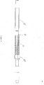
- Figure 1 is a perspective view of an exemplary embodiment of a retrieval tool 100.
- Figure 1A is a cross-sectional view of the retrieval tool 100.
- Figure 2 is an enlarged cross-sectional view of the retrieval tool 100 shown without the mandrel, and
- Figure 2A is an enlarged, partial view of Figure 2 .
- Figure 3 is another cross-sectional view of the retrieval tool 100.
- Figure 4 is a partial, perspective view of the retrieval tool 100.
- the retrieval tool 100 is a magnetic retrieval tool suitable for retrieving metallic debris from the wellbore.
- the retrieval tool 100 includes a mandrel 10 having a central bore 12 and upper and lower ends 13, 14 adapted for connection to a work string or other downhole tools.
- the inner sleeve 30 is disposed around the mandrel 10.
- the inner sleeve 30 includes a plurality of circumferentially spaced axial channels 32 for receiving a plurality of magnets 50, as shown in the cross-sectional views of Figures 3 and 4A .
- the inner sleeve 30 may include any suitable number of axial channels 32, such as six channels or between two to eight channels, or more.
- the channels 32 may be recessed to help prevent the magnets 50 from moving circumferentially toward an adjacent magnet 50.
- a plurality of apertures 33 may be formed in the axial channels 32 for mating with a fastener 55 for retaining the magnet 50 in position.
- the aperture 33 may be a configured to mate with a bolt 55.
- a non-metallic spacer 40 may be disposed between two adjacent magnets 50 in a channel 32.
- a spacer 40 is disposed in front of some of the magnets 50.
- the spacer 40 may be attached to the magnet 50 or the inner sleeve 30 using an adhesive, a fastener, or any other suitable mechanisms.
- the inner sleeve 30 may optionally include a plurality of assembly apertures 36 disposed between two adjacent channels 30.
- the assembly apertures 36 may be formed in a circumferential slot 134 on the inner sleeve 30. In one embodiment, two columns of assembly apertures 36 are formed at 180 degrees from each other along the inner sleeve 30.
- the assembly apertures 36 may be used to hold the assembly tool 200 in place during assembly.
- Figure 5 illustrates an exemplary embodiment of a magnet 50.
- the magnet 50 may have a rectangular shape.
- the width of the magnet 50 is sized to fit within the channel 32 on the inner sleeve 30, and the height may be taller than the channel 32. If the magnets 50 protrude from the channel 32, the space between two adjacent columns of magnets 50 may be referred to as the "valley" 59, as shown in Figure 4A .
- the magnet 50 may have any suitable length. In one example, the magnet 50 has a length between 3 and 5 inches, a width between 1 and 2 inches, and a height between 0.5 and 1 inches. In another example, the magnet 50 has a length between 1 and 8 inches, a width between 0.5 and 4 inches, and a height between 0.25 and 2 inches.
- the magnet 50 may have one or more apertures 53 through the top surface for receiving the fastener 55 that will mate with the aperture 33 in the inner sleeve 30. As shown, the magnet 50 is provided with one aperture 53, which optionally includes a countersink in the aperture 53. In one embodiment, the sides of magnet 50 may include a plurality of retainer bores 54 for receiving a retainer of the assembly tool 200, as will be described below. Although two retainer bores 54 are shown, it is contemplated that the magnet 50 may include any suitable number of retainer bores 54, such as one, three, or four. It is further contemplated that the number of the retainers used may be less than or equal to the number of retainer bores 54. For example, only one retainer, such as a pin, is used even if two bores 54 are present.
- the "north" pole and the “south” pole of the magnet are oriented on either the left side or the right side of the magnet.
- the north pole may be on the left side and the south pole may be on the right side of the magnet 50. In use, this north and south arrangement maximizes the collection of debris in the valley 59 between two columns of magnets 50.
- the retrieval tool 100 may include a housing sleeve 25 disposed around the magnets 50 and the inner sleeve 30.
- the housing sleeve 25 may conformed to the contour of the retrieval tool 100 formed by the magnets 50 and the inner sleeve 30.
- the housing sleeve 25 may have an outer shape that is complementary to the outer shape of the magnets 50 on the inner sleeve 30.
- the housing sleeve 25 includes valleys 29 that are aligned with the valleys 59 between adjacent columns of magnets 50.
- a stabilizer 20 may be disposed at each end of the inner sleeve 30.
- the stabilizer 20 may have an outer diameter that is larger than the outer diameter of the housing sleeve 25.
- at least a portion of the inner diameter of stabilizer 20 has an inner recess 22 that complements the outer profile of the housing sleeve 25.
- the outer shape of the stabilizer 20 may include a valley 26 that is aligned with a valley 29 of the housing sleeve 25, as shown in Figure 3 .
- One or more keys 45 may be disposed on an axial channel 32 and adapted to engage a groove 23 in the stabilizer 20. As shown, two keys 45 are used at each stabilizer 20.
- a fastener 55 such as a bolt may be inserted through an aperture 24 to fasten the stabilizer 20 to the key 45.
- the inner sleeve 30, magnets 50, outer sleeve 25, and the stabilizer 20 may be rotatable with each other.
- the keys 45 may have a recess 47 to receive the housing sleeve 25, and may be used to limit axial movement of the housing sleeve 25 relative to the magnets 50.
- a bearing 15 may be disposed between stabilizer 20 and the mandrel 10.
- Figure 7A is a perspective view of an exemplary mandrel 10 with a lower end 14 and a recessed portion 17.
- the upper end 13 is removed to expose a recessed end 19 on the mandrel 10.
- Figure 7B shows a bearing 15 and a stabilizer 20 disposed proximate a lower end 14 of the mandrel 10.
- the bearing 15 and the stabilizer 20 are disposed in the recessed portion 17 of the mandrel 10.
- the bearing 15 and the stabilizer 20 may be inserted onto the recessed portion 17 from the recessed end 19 of the mandrel 10.
- an extension mandrel 110 is temporarily attached to the recessed end 19 of the mandrel 10.
- the extension mandrel 110 may be used to facilitate assembly of the magnets 50 on the retrieval tool 100.
- the extension mandrel 110 has an outer diameter that is substantially the same as the outer diameter of the recess portion 17 of the mandrel 10.
- the inner sleeve 30 is positioned around the extension mandrel 110.
- a fastener 112 such as a bolt or pin is used to attach the inner sleeve 30 to the extension mandrel 110.
- an extension sleeve 130 is positioned around the extension mandrel 110 and adjacent the inner sleeve 30.
- the extension sleeve 130 includes channels 132 that are placed in alignment with the channels 32 of the inner sleeve 30.
- Figure 7G is an enlarged partial view of Figure 7F .
- Figure 7G shows another fastener 112 is used to temporarily attach the extension sleeve 130 to the extension mandrel 110.
- a plurality of circumferential slots 134 are formed on the exterior of the inner sleeve 30 and the extension sleeve 130.
- the assembly apertures 36 are formed through the slots 134.
- Figure 4 shows a perspective view of the slots 134 and assembly apertures 36 on the inner sleeve 30.
- FIG 8 illustrates an exemplary embodiment of the assembly tool 200.
- the assembly tool 200 includes an anchor 210, a conveyance 220, and a holder 230.
- the anchor 210 includes a collar 211 and a locking device 213.
- the collar 211 is configured to be disposed around the inner sleeve 30 and the extension sleeve 130.
- the locking device 213 may include a retractable pin configured to mate with the assembly aperture 36 in the slots 134.
- a plurality of locking devices 213 may be used.
- the anchor 210 includes two locking devices 213.
- the locking device 213 may be any releasable locking device suitable for attaching the anchor 210 to the inner sleeve 30 and the extension sleeve 130, for example, bolts, latches, pins, or dogs.
- the locking device 130 may be biased in the engaged positioned using, for example, a spring.
- the conveyance 220 is configured to extend or retract the holder 230.
- the conveyance 220 is movable relative to the anchor 210.
- the conveyance 220 may be a rod 221 configured to mate with one or more couplers 223 attached to the collar 211.
- the rod 221 is threadedly coupled to the coupler 223. In this respect, rotation of the rod 221 will move the rod 221 relative to the collar 211.
- the coupler 223 is a nut, and three couplers 223 are used to couple the rod 221 to the collar 211.
- the rod 221 may be rotated manually or using a motor.
- gears may be used to move the conveyance 220 relative to the collar 211.
- the rod 221 may be coupled to the coupler 223 using splines, and maybe moved manually, or using a mechanical device such as a motor or a piston.
- the holder 230 is coupled to and movable by the conveyance 220.
- the holder 230 includes two retaining arms 231 configured to retain a magnet between the arms 231.
- An optional guide member 233 may be disposed on the exterior of the arms 231.
- the guide member 233 is configured to prevent movement of the holder 230 toward an adjacent magnet.
- the guide member 233 is sized to contact or nearly contact the adjacent magnet.
- the guide member 233 may be attached to the arm 231 using a pin, a screw, adhesive, or any suitable mechanism known to a person skilled in the art.
- the arms and/or the guide member may be made of a non-metallic material.
- the guide member 233 may be integral with the arms 233. Any suitable releasable retainer may be used to couple the magnet to the holder 230.
- a pin 234 may be inserted through one of the arms 231 and the retainer bore 54 of the magnet 50.
- Figure 9 shows the assembly tool 200 installed on the inner sleeve 30 to begin the magnet assembly process.
- the collar 211 is disposed around the inner sleeve 30 and the locking device 213 is engaged with an assembly aperture 36 in the inner sleeve 30.
- Figure 9A is an enlarged side view of the assembly tool 200 in Figure 9 . It can be seen that one side of the guide member 233 is aligned with an adjacent channel 32.
- Figure 9B is an enlarged top view of the assembly tool 200 in Figure 9 . It can be seen the two arms 231 are aligned with edges of the channel 32 receiving the magnet.
- a magnet 50 is positioned between the arms 231 of the assembly tool 200 and in a channel 32 of the inner sleeve 30. Also, the pin 234 is inserted into the retainer bore 54 of the magnet 50. The conveyance 220 is then rotated to move the magnet 50 along the channel 32 to the desired location on the inner sleeve 30.
- Figure 11 the magnet 50 has moved to the desired location, and the aperture 53 in the magnet 50 is aligned with the aperture 33 of the inner sleeve 30. Thereafter, a bolt 55 is used to attach the magnet 50 to the inner sleeve 30.
- Figure 11A shows an exemplary embodiment of a bolt 55 and an optional washer 57.
- Figure 11B is an enlarged view of the holder 230 and the magnet 50, just before the bolt 55 is inserted into the magnet 50 and the inner sleeve 30 via apertures 53, 33.
- Figure 11C shows the magnet 50 after the bolt 55 has been inserted, thereby attaching the magnet 50 to the inner sleeve 30.
- the collar 211 is released from the inner sleeve 30 by unlocking the locking device 213. Then, the collar 211 is rotated until the holder 230 is aligned with the next intended channel 32, and the locking device 213 is allowed to engage with the inner sleeve 30, as shown in Figure 12 . In one embodiment, rotation of the collar 211 may be guided by the slot 134 in the inner sleeve 30. To reposition the collar 211 axially, the collar 211 is moved axially until the locking device 213 engages a slot 134 on the inner sleeve 30. Then, the collar 211 is rotated until locking device 213 engages the aperture 36 in the inner sleeve 30.
- Figure 12A shows a row of magnets 50a assembled on the inner sleeve 30, and a magnet 50b is held by the holder 220. It must noted that the magnets 50a may be assembled in any suitable order, such as installing two magnets in each channel before repositioning the assembly tool 200 to install a magnet in another channel.
- an optional spacer 40 is disposed between two magnets 50a, 50b in the same channel 32.
- Figure 12C shows the magnets 50a, 50b in position and attached to the inner sleeve 30. The holder 230 is ready to be repositioned to install the next magnet in the second row of a different channel 32. This process may be repeated until all of magnets 50 are installed.
- Figure 12D shows all of the magnets 50 assembled on channels 32 of the inner sleeve 30. A spacer 40 disposed between two adjacent magnets 50 in the same channel 32.
- the inner sleeve 30 is released from the extension mandrel 110 by removing the fastener 112.
- the inner sleeve 30 is moved onto the mandrel 10 toward the stabilizer 20, as shown in Figure 13A .
- Figure 13B which is a partial view, two keys 45 are positioned at the end of the inner sleeve 30. As shown, the keys 45 are located in channels 32 on opposite sides of the inner sleeve 30.
- spacers 40 are disposed in channels 32 and adjacent to the magnet 50 at the end. Spacers 40 may optionally be disposed between a magnet 50 and the key 45.
- the inner sleeve 30 is inserted into the stabilizer 20 until the keys 45 are in the groove 23 of the stabilizer 20.
- the keys 45 are attached to the stabilizer 20 using a bolt 55.
- the bearing 15, stabilizer 20, and the magnets 50 are optionally moved to one end of the recess 17 in the mandrel 10 to continue the installation process.
- the housing sleeve 25 is ready to be positioned around the magnets 50.
- the housing sleeve 25 has a profile that complements the shape of the magnets 50 and the inner sleeve 30. As previously described, the housing 25 have valleys 29 that are aligned with the valleys 59 between the magnets 50.
- Figure 14A is a cross-sectional view of the retrieval tool 100 after the housing sleeve 25 has been installed.
- Figure 14B is an enlarged view showing the housing sleeve 25 disposed between the keys 45 and the stabilizer 20. In this embodiment, the housing sleeve 25 is received in the recess 47 of the keys 45.
- Figure 14C the lower stabilizer 20 has been moved to the lower end of the recessed portion 17, and the other stabilizer 20 and bearing 15 are positioned on the upper end of the mandrel 10.
- Figure 14D is a cross-sectional view of the retrieval tool 100 after the upper stabilizer 20 has been installed.
- Figure 14E is an enlarged partial view showing the keys 45 disposed on the inner sleeve 30, and the stabilizer 20 is attached to the keys 45 using bolts 55. Thereafter, the extension mandrel 110 is released from the mandrel 10. Then, the upper end 13 is attached to the mandrel 10 to complete the assembly, as shown in Figures 1 and 1A .
- a downhole retrieval tool in one embodiment, includes a mandrel; an inner sleeve disposed around the mandrel; a plurality of magnets coupled to the inner sleeve; and an outer sleeve disposed around the plurality of magnets, wherein the inner sleeve and the plurality of magnets are rotatable relative to the mandrel.
- the inner sleeve includes one or more channels for receiving the plurality of magnets.
- each magnet includes a "north” pole and a “south” pole," wherein the north pole is disposed on the left side or the right side of the magnet and the south pole is disposed on the other side of the magnet.
- the tool includes a stabilizer coupled to each end of the inner sleeve.
- the tool includes a bearing disposed between the stabilizer and the mandrel.
- the tool includes a key and groove connection for coupling the inner sleeve to the stabilizer.
- the stabilizer includes a valley aligned with a valley of the inner sleeve.
- the tool includes a spacer disposed between two adjacent magnets.
- At least one magnet includes a retainer bore to facilitate handling of the at least one magnet.
- a method of assembling a downhole retrieval tool includes providing an assembly tool having an anchor, a conveyance, and a holder; disposing an inner sleeve around a mandrel; coupling the anchor to the inner sleeve; using the holder to retain a magnet; operating the conveyance to move the magnet to a desired location on the inner sleeve; attaching the magnet to the inner sleeve; and moving the holder away from the magnet.
- the method incudes decoupling the anchor from the inner sleeve; repositioning the anchor; retaining a second magnet; and operating the conveyance to move the second magnet to another location on the inner sleeve.
- the method includes repositioning the anchor by at least one of rotating the anchor relative to the inner sleeve and axially moving the anchor relative to the inner sleeve.
- coupling the anchor to the inner sleeve comprises inserting a locking device into an aperture of the inner sleeve.
- the inner sleeve includes a slot for receiving the locking device.
- the conveyance is coupled to the anchor using threads, and operating the conveyance comprises rotating the conveyance relative to the anchor.
- retaining the magnet comprises inserting a retainer into a retainer bore in the magnet.
- the method includes providing the assembly tool with a guide member.
- an assembly tool for handling a magnet includes an anchor; a conveyance movable relative to the anchor; and a magnet holder coupled to and movable with the conveyance, wherein the magnet holder includes an arm for retaining the magnet.
- the tool includes a retainer for coupling with a retainer bore in the magnet.
- the retainer is inserted through the arm of the magnet holder.
- the anchor is tubular shaped and includes a retracting locking device for anchoring the assembly tool.
- the conveyance is threadedly coupled to the anchor.
- the tool includes a guide member attached to the arm.
- a method of assembling a downhole retrieval tool includes providing an assembly tool having an anchor, a conveyance, and a holder; disposing an inner sleeve around a mandrel; coupling anchor to the inner sleeve; using the holder to retain a magnet; operating the conveyance to move the magnet to a desired location on the inner sleeve; attaching the magnet to the inner sleeve; and moving the holder away from the magnet.
- an assembly tool for handling a magnet includes an anchor; a conveyance movable relative to the anchor; and a magnet holder coupled to the conveyance, wherein the magnet holder includes an arm for retaining the magnet.
Abstract
Description
- Embodiments of the invention generally relate to apparatus and methods for removing material from a wellbore. Particularly, embodiments of the invention relate to a magnetic retrieval apparatus. Embodiments of the invention also relate to apparatus and methods of assembling a magnetic retrieval apparatus.
- Many operations in an oil or gas well often produce a variety of debris in the wellbore. For example, milling operations may produce metallic mill cuttings, which may not be completely removed by circulation of fluid in the wellbore. Also, bit cones, slips, tong pins, and hammers, or fragments thereof, can collect at the bottom of the wellbore.
- Retrieval tools containing magnets have been used to retrieve the debris in the wellbore. One type of retrieval tool includes a plurality of magnets disposed on its exterior, and the magnets may be exposed to the wellbore environment surrounding the retrieval tool. The exposed magnets are subjected to physical damage or corrosion in the wellbore, and in some instances, may even be lost in the wellbore.
- The handling of magnets during assembly of the retrieval tool raises safety concerns. Large, high strength magnets may be pulled out of the operator's hand by an adjacent magnet.
- There is a need, therefore, for an improved retrieval tool for retrieving debris from the wellbore. There is also a need for apparatus and methods of assembling a retrieval tool.
- In accordance with one aspect of the present invention there is provided a downhole retrieval tool comprising a mandrel; an inner sleeve disposed around the mandrel; a plurality of magnets coupled to the inner sleeve; and an outer sleeve disposed around the plurality of magnets, wherein the inner sleeve and the plurality of magnets are rotatable relative to the mandrel.
- In accordance with another aspect of the present invention there is provided a method of assembling a downhole retrieval tool, comprising providing an assembly tool having an anchor, a conveyance, and a holder; disposing an inner sleeve around a mandrel; coupling the anchor to the inner sleeve; using the holder to retain a magnet; operating the conveyance to move the magnet to a desired location on the inner sleeve; attaching the magnet to the inner sleeve; and moving the holder away from the magnet.
- In accordance with another aspect of the present invention there is provided an assembly tool for handling a magnet, comprising an anchor; a conveyance movable relative to the anchor; and a magnet holder coupled to the conveyance, wherein the magnet holder includes an arm for retaining the magnet.
- Further aspects and preferred features are set out in
claim 2 et seq. - So that the manner in which the above recited features of the present invention can be understood in detail, a more particular description of the invention, briefly summarized above, may be had by reference to embodiments, some of which are illustrated in the appended drawings. It is to be noted, however, that the appended drawings illustrate only typical embodiments of this invention and are therefore not to be considered limiting of its scope, for the invention may admit to other equally effective embodiments.
-
Figure 1 is a perspective view of an exemplary embodiment of aretrieval tool 100.Figure 1A is a cross-sectional view of the retrieval tool. -
Figure 2 is an enlarged cross-sectional view of the retrieval tool without the mandrel, andFigure 2A is an enlarged, partial view ofFigure 2 . -
Figure 3 is another cross-sectional view of the retrieval tool. -
Figure 4 is a partial, perspective view of the retrieval tool.Figure 4A is a cross-sectional view of the retrieval tool ofFigure 4 . -
Figure 5 illustrates an exemplary embodiment of a magnet. -
Figure 6 illustrates an exemplary embodiment of a stabilizer. -
Figures 7A-7G are sequential views of the initial steps of an exemplary process of assembling a retrieval tool. -
Figure 8 illustrate an exemplary embodiment of an assembly tool. -
Figures 9-11C are sequential views of additional steps of the process of assembling a retrieval tool shown after the steps shown inFigures 7A-7G . -
Figures 12-14E are sequential views of additional steps of the process of assembling a retrieval tool after the steps shown inFigures 9-11C . -
Figure 1 is a perspective view of an exemplary embodiment of aretrieval tool 100.Figure 1A is a cross-sectional view of theretrieval tool 100.Figure 2 is an enlarged cross-sectional view of theretrieval tool 100 shown without the mandrel, andFigure 2A is an enlarged, partial view ofFigure 2 .Figure 3 is another cross-sectional view of theretrieval tool 100.Figure 4 is a partial, perspective view of theretrieval tool 100. As shown in these Figures, theretrieval tool 100 is a magnetic retrieval tool suitable for retrieving metallic debris from the wellbore. Theretrieval tool 100 includes amandrel 10 having acentral bore 12 and upper andlower ends - Referring now to
Figures 2, 2A , and3 aninner sleeve 30 is disposed around themandrel 10. Theinner sleeve 30 includes a plurality of circumferentially spacedaxial channels 32 for receiving a plurality ofmagnets 50, as shown in the cross-sectional views ofFigures 3 and4A . Theinner sleeve 30 may include any suitable number ofaxial channels 32, such as six channels or between two to eight channels, or more. Thechannels 32 may be recessed to help prevent themagnets 50 from moving circumferentially toward anadjacent magnet 50. A plurality ofapertures 33 may be formed in theaxial channels 32 for mating with afastener 55 for retaining themagnet 50 in position. For example, theaperture 33 may be a configured to mate with abolt 55. Optionally, anon-metallic spacer 40 may be disposed between twoadjacent magnets 50 in achannel 32. InFigure 4A , aspacer 40 is disposed in front of some of themagnets 50. Thespacer 40 may be attached to themagnet 50 or theinner sleeve 30 using an adhesive, a fastener, or any other suitable mechanisms. As will be described below and shown inFigure 4 , theinner sleeve 30 may optionally include a plurality ofassembly apertures 36 disposed between twoadjacent channels 30. Theassembly apertures 36 may be formed in acircumferential slot 134 on theinner sleeve 30. In one embodiment, two columns ofassembly apertures 36 are formed at 180 degrees from each other along theinner sleeve 30. Theassembly apertures 36 may be used to hold theassembly tool 200 in place during assembly. -
Figure 5 illustrates an exemplary embodiment of amagnet 50. Themagnet 50 may have a rectangular shape. The width of themagnet 50 is sized to fit within thechannel 32 on theinner sleeve 30, and the height may be taller than thechannel 32. If themagnets 50 protrude from thechannel 32, the space between two adjacent columns ofmagnets 50 may be referred to as the "valley" 59, as shown inFigure 4A . Themagnet 50 may have any suitable length. In one example, themagnet 50 has a length between 3 and 5 inches, a width between 1 and 2 inches, and a height between 0.5 and 1 inches. In another example, themagnet 50 has a length between 1 and 8 inches, a width between 0.5 and 4 inches, and a height between 0.25 and 2 inches. Themagnet 50 may have one ormore apertures 53 through the top surface for receiving thefastener 55 that will mate with theaperture 33 in theinner sleeve 30. As shown, themagnet 50 is provided with oneaperture 53, which optionally includes a countersink in theaperture 53. In one embodiment, the sides ofmagnet 50 may include a plurality ofretainer bores 54 for receiving a retainer of theassembly tool 200, as will be described below. Although tworetainer bores 54 are shown, it is contemplated that themagnet 50 may include any suitable number ofretainer bores 54, such as one, three, or four. It is further contemplated that the number of the retainers used may be less than or equal to the number ofretainer bores 54. For example, only one retainer, such as a pin, is used even if twobores 54 are present. - In one embodiment, the "north" pole and the "south" pole of the magnet are oriented on either the left side or the right side of the magnet. For example, as shown in
Figures 3 and4A , the north pole may be on the left side and the south pole may be on the right side of themagnet 50. In use, this north and south arrangement maximizes the collection of debris in thevalley 59 between two columns ofmagnets 50. - The
retrieval tool 100 may include ahousing sleeve 25 disposed around themagnets 50 and theinner sleeve 30. Thehousing sleeve 25 may conformed to the contour of theretrieval tool 100 formed by themagnets 50 and theinner sleeve 30. In one example, thehousing sleeve 25 may have an outer shape that is complementary to the outer shape of themagnets 50 on theinner sleeve 30. In this respect, thehousing sleeve 25 includesvalleys 29 that are aligned with thevalleys 59 between adjacent columns ofmagnets 50. - A
stabilizer 20 may be disposed at each end of theinner sleeve 30. Referring toFigures 2 ,4 , and6 , thestabilizer 20 may have an outer diameter that is larger than the outer diameter of thehousing sleeve 25. In one embodiment, at least a portion of the inner diameter ofstabilizer 20 has aninner recess 22 that complements the outer profile of thehousing sleeve 25. The outer shape of thestabilizer 20 may include avalley 26 that is aligned with avalley 29 of thehousing sleeve 25, as shown inFigure 3 . One ormore keys 45 may be disposed on anaxial channel 32 and adapted to engage agroove 23 in thestabilizer 20. As shown, twokeys 45 are used at eachstabilizer 20. Afastener 55 such as a bolt may be inserted through anaperture 24 to fasten thestabilizer 20 to the key 45. In this respect, theinner sleeve 30,magnets 50,outer sleeve 25, and thestabilizer 20 may be rotatable with each other. In one embodiment, thekeys 45 may have arecess 47 to receive thehousing sleeve 25, and may be used to limit axial movement of thehousing sleeve 25 relative to themagnets 50. In another embodiment, abearing 15 may be disposed betweenstabilizer 20 and themandrel 10. - Assembly of the
retrieval tool 100 will now be described.Figure 7A is a perspective view of anexemplary mandrel 10 with alower end 14 and a recessedportion 17. During installation of themagnets 50, theupper end 13 is removed to expose a recessedend 19 on themandrel 10.Figure 7B shows abearing 15 and astabilizer 20 disposed proximate alower end 14 of themandrel 10. In this embodiment, thebearing 15 and thestabilizer 20 are disposed in the recessedportion 17 of themandrel 10. Thebearing 15 and thestabilizer 20 may be inserted onto the recessedportion 17 from the recessedend 19 of themandrel 10. - In
Figure 7C , anextension mandrel 110 is temporarily attached to the recessedend 19 of themandrel 10. Theextension mandrel 110 may be used to facilitate assembly of themagnets 50 on theretrieval tool 100. Theextension mandrel 110 has an outer diameter that is substantially the same as the outer diameter of therecess portion 17 of themandrel 10. - In
Figure 7D , theinner sleeve 30 is positioned around theextension mandrel 110. As shown inFigure 7E , which is an enlarged partial view ofFigure 7D , afastener 112 such as a bolt or pin is used to attach theinner sleeve 30 to theextension mandrel 110. InFigure 7F , anextension sleeve 130 is positioned around theextension mandrel 110 and adjacent theinner sleeve 30. Theextension sleeve 130 includes channels 132 that are placed in alignment with thechannels 32 of theinner sleeve 30.Figure 7G is an enlarged partial view ofFigure 7F .Figure 7G shows anotherfastener 112 is used to temporarily attach theextension sleeve 130 to theextension mandrel 110. A plurality ofcircumferential slots 134 are formed on the exterior of theinner sleeve 30 and theextension sleeve 130. The assembly apertures 36 are formed through theslots 134.Figure 4 shows a perspective view of theslots 134 andassembly apertures 36 on theinner sleeve 30. -
Figure 8 illustrates an exemplary embodiment of theassembly tool 200. Theassembly tool 200 includes ananchor 210, aconveyance 220, and aholder 230. Theanchor 210 includes acollar 211 and alocking device 213. Thecollar 211 is configured to be disposed around theinner sleeve 30 and theextension sleeve 130. Thelocking device 213 may include a retractable pin configured to mate with theassembly aperture 36 in theslots 134. A plurality of lockingdevices 213 may be used. As shown, theanchor 210 includes twolocking devices 213. It is contemplated that thelocking device 213 may be any releasable locking device suitable for attaching theanchor 210 to theinner sleeve 30 and theextension sleeve 130, for example, bolts, latches, pins, or dogs. Thelocking device 130 may be biased in the engaged positioned using, for example, a spring. - The
conveyance 220 is configured to extend or retract theholder 230. In one embodiment, theconveyance 220 is movable relative to theanchor 210. Theconveyance 220 may be arod 221 configured to mate with one ormore couplers 223 attached to thecollar 211. In one example, therod 221 is threadedly coupled to thecoupler 223. In this respect, rotation of therod 221 will move therod 221 relative to thecollar 211. In one example, thecoupler 223 is a nut, and threecouplers 223 are used to couple therod 221 to thecollar 211. Therod 221 may be rotated manually or using a motor. In another example, gears may be used to move theconveyance 220 relative to thecollar 211. In yet another embodiment, therod 221 may be coupled to thecoupler 223 using splines, and maybe moved manually, or using a mechanical device such as a motor or a piston. - The
holder 230 is coupled to and movable by theconveyance 220. Theholder 230 includes two retainingarms 231 configured to retain a magnet between thearms 231. Anoptional guide member 233 may be disposed on the exterior of thearms 231. Theguide member 233 is configured to prevent movement of theholder 230 toward an adjacent magnet. In one embodiment, theguide member 233 is sized to contact or nearly contact the adjacent magnet. Theguide member 233 may be attached to thearm 231 using a pin, a screw, adhesive, or any suitable mechanism known to a person skilled in the art. The arms and/or the guide member may be made of a non-metallic material. In another embodiment, theguide member 233 may be integral with thearms 233. Any suitable releasable retainer may be used to couple the magnet to theholder 230. In one example, apin 234 may be inserted through one of thearms 231 and the retainer bore 54 of themagnet 50. -
Figure 9 shows theassembly tool 200 installed on theinner sleeve 30 to begin the magnet assembly process. As shown, thecollar 211 is disposed around theinner sleeve 30 and thelocking device 213 is engaged with anassembly aperture 36 in theinner sleeve 30.Figure 9A is an enlarged side view of theassembly tool 200 inFigure 9 . It can be seen that one side of theguide member 233 is aligned with anadjacent channel 32.Figure 9B is an enlarged top view of theassembly tool 200 inFigure 9 . It can be seen the twoarms 231 are aligned with edges of thechannel 32 receiving the magnet. - In
Figure 10 , amagnet 50 is positioned between thearms 231 of theassembly tool 200 and in achannel 32 of theinner sleeve 30. Also, thepin 234 is inserted into the retainer bore 54 of themagnet 50. Theconveyance 220 is then rotated to move themagnet 50 along thechannel 32 to the desired location on theinner sleeve 30. - In
Figure 11 , themagnet 50 has moved to the desired location, and theaperture 53 in themagnet 50 is aligned with theaperture 33 of theinner sleeve 30. Thereafter, abolt 55 is used to attach themagnet 50 to theinner sleeve 30.Figure 11A shows an exemplary embodiment of abolt 55 and anoptional washer 57.Figure 11B is an enlarged view of theholder 230 and themagnet 50, just before thebolt 55 is inserted into themagnet 50 and theinner sleeve 30 viaapertures Figure 11C shows themagnet 50 after thebolt 55 has been inserted, thereby attaching themagnet 50 to theinner sleeve 30. - Thereafter, the
pin 234 is released from themagnet 50, and theholder 230 is retracted from themagnet 50. - To install another magnet, the
collar 211 is released from theinner sleeve 30 by unlocking thelocking device 213. Then, thecollar 211 is rotated until theholder 230 is aligned with the next intendedchannel 32, and thelocking device 213 is allowed to engage with theinner sleeve 30, as shown inFigure 12 . In one embodiment, rotation of thecollar 211 may be guided by theslot 134 in theinner sleeve 30. To reposition thecollar 211 axially, thecollar 211 is moved axially until thelocking device 213 engages aslot 134 on theinner sleeve 30. Then, thecollar 211 is rotated until lockingdevice 213 engages theaperture 36 in theinner sleeve 30.Figure 12A shows a row ofmagnets 50a assembled on theinner sleeve 30, and a magnet 50b is held by theholder 220. It must noted that themagnets 50a may be assembled in any suitable order, such as installing two magnets in each channel before repositioning theassembly tool 200 to install a magnet in another channel. InFigure 12B , anoptional spacer 40 is disposed between twomagnets 50a, 50b in thesame channel 32.Figure 12C shows themagnets 50a, 50b in position and attached to theinner sleeve 30. Theholder 230 is ready to be repositioned to install the next magnet in the second row of adifferent channel 32. This process may be repeated until all ofmagnets 50 are installed.Figure 12D shows all of themagnets 50 assembled onchannels 32 of theinner sleeve 30. Aspacer 40 disposed between twoadjacent magnets 50 in thesame channel 32. - Thereafter, the
inner sleeve 30 is released from theextension mandrel 110 by removing thefastener 112. Theinner sleeve 30 is moved onto themandrel 10 toward thestabilizer 20, as shown inFigure 13A . InFigure 13B , ,which is a partial view, twokeys 45 are positioned at the end of theinner sleeve 30. As shown, thekeys 45 are located inchannels 32 on opposite sides of theinner sleeve 30. InFigure 13C , spacers 40 are disposed inchannels 32 and adjacent to themagnet 50 at the end.Spacers 40 may optionally be disposed between amagnet 50 and the key 45. InFigure 13D , theinner sleeve 30 is inserted into thestabilizer 20 until thekeys 45 are in thegroove 23 of thestabilizer 20. InFigure 13E , thekeys 45 are attached to thestabilizer 20 using abolt 55. In one embodiment, thebearing 15,stabilizer 20, and themagnets 50 are optionally moved to one end of therecess 17 in themandrel 10 to continue the installation process. - In
Figure 14 , thehousing sleeve 25 is ready to be positioned around themagnets 50. Thehousing sleeve 25 has a profile that complements the shape of themagnets 50 and theinner sleeve 30. As previously described, thehousing 25 havevalleys 29 that are aligned with thevalleys 59 between themagnets 50.Figure 14A is a cross-sectional view of theretrieval tool 100 after thehousing sleeve 25 has been installed.Figure 14B is an enlarged view showing thehousing sleeve 25 disposed between thekeys 45 and thestabilizer 20. In this embodiment, thehousing sleeve 25 is received in therecess 47 of thekeys 45. InFigure 14C , thelower stabilizer 20 has been moved to the lower end of the recessedportion 17, and theother stabilizer 20 andbearing 15 are positioned on the upper end of themandrel 10.Figure 14D is a cross-sectional view of theretrieval tool 100 after theupper stabilizer 20 has been installed.Figure 14E is an enlarged partial view showing thekeys 45 disposed on theinner sleeve 30, and thestabilizer 20 is attached to thekeys 45 usingbolts 55. Thereafter, theextension mandrel 110 is released from themandrel 10. Then, theupper end 13 is attached to themandrel 10 to complete the assembly, as shown inFigures 1 and 1A . - In one embodiment, a downhole retrieval tool includes a mandrel; an inner sleeve disposed around the mandrel; a plurality of magnets coupled to the inner sleeve; and an outer sleeve disposed around the plurality of magnets, wherein the inner sleeve and the plurality of magnets are rotatable relative to the mandrel.
- In one or more of the embodiments described herein, the inner sleeve includes one or more channels for receiving the plurality of magnets.
- In one or more of the embodiments described herein, each magnet includes a "north" pole and a "south" pole," wherein the north pole is disposed on the left side or the right side of the magnet and the south pole is disposed on the other side of the magnet.
- In one or more of the embodiments described herein, the tool includes a stabilizer coupled to each end of the inner sleeve.
- In one or more of the embodiments described herein, the tool includes a bearing disposed between the stabilizer and the mandrel.
- In one or more of the embodiments described herein, the tool includes a key and groove connection for coupling the inner sleeve to the stabilizer.
- In one or more of the embodiments described herein, the stabilizer includes a valley aligned with a valley of the inner sleeve.
- In one or more of the embodiments described herein, the tool includes a spacer disposed between two adjacent magnets.
- In one or more of the embodiments described herein, at least one magnet includes a retainer bore to facilitate handling of the at least one magnet.
- In an embodiment, a method of assembling a downhole retrieval tool includes providing an assembly tool having an anchor, a conveyance, and a holder; disposing an inner sleeve around a mandrel; coupling the anchor to the inner sleeve; using the holder to retain a magnet; operating the conveyance to move the magnet to a desired location on the inner sleeve; attaching the magnet to the inner sleeve; and moving the holder away from the magnet.
- In one or more of the embodiments described herein, the method incudes decoupling the anchor from the inner sleeve; repositioning the anchor; retaining a second magnet; and operating the conveyance to move the second magnet to another location on the inner sleeve.
- In one or more of the embodiments described herein, the method includes repositioning the anchor by at least one of rotating the anchor relative to the inner sleeve and axially moving the anchor relative to the inner sleeve.
- In one or more of the embodiments described herein, coupling the anchor to the inner sleeve comprises inserting a locking device into an aperture of the inner sleeve.
- In one or more of the embodiments described herein, the inner sleeve includes a slot for receiving the locking device.
- In one or more of the embodiments described herein, the conveyance is coupled to the anchor using threads, and operating the conveyance comprises rotating the conveyance relative to the anchor.
- In one or more of the embodiments described herein, retaining the magnet comprises inserting a retainer into a retainer bore in the magnet.
- In one or more of the embodiments described herein, the method includes providing the assembly tool with a guide member.
- In an embodiment, an assembly tool for handling a magnet includes an anchor; a conveyance movable relative to the anchor; and a magnet holder coupled to and movable with the conveyance, wherein the magnet holder includes an arm for retaining the magnet.
- In one or more of the embodiments described herein, the tool includes a retainer for coupling with a retainer bore in the magnet.
- In one or more of the embodiments described herein, the retainer is inserted through the arm of the magnet holder.
- In one or more of the embodiments described herein, the anchor is tubular shaped and includes a retracting locking device for anchoring the assembly tool.
- In one or more of the embodiments described herein, the conveyance is threadedly coupled to the anchor.
- In one or more of the embodiments described herein, the tool includes a guide member attached to the arm.
- In an embodiment, a method of assembling a downhole retrieval tool includes providing an assembly tool having an anchor, a conveyance, and a holder; disposing an inner sleeve around a mandrel; coupling anchor to the inner sleeve; using the holder to retain a magnet; operating the conveyance to move the magnet to a desired location on the inner sleeve; attaching the magnet to the inner sleeve; and moving the holder away from the magnet.
- In an embodiment, an assembly tool for handling a magnet includes an anchor; a conveyance movable relative to the anchor; and a magnet holder coupled to the conveyance, wherein the magnet holder includes an arm for retaining the magnet.
- The features and mechanisms of each embodiment may be interchangeable with the other embodiments described herein. Additionally, while the foregoing is directed to embodiments of the present invention, other and further embodiments of the invention may be devised without departing from the basic scope thereof, and the scope thereof is determined by the claims that follow.
Claims (15)
- A downhole retrieval tool, comprising:a mandrel;an inner sleeve disposed around the mandrel;a plurality of magnets coupled to the inner sleeve; andan outer sleeve disposed around the plurality of magnets, wherein the inner sleeve and the plurality of magnets are rotatable relative to the mandrel.
- The tool of claim 1, wherein the inner sleeve includes one or more channels for receiving the plurality of magnets.
- The tool of claim 1 or 2, wherein each magnet includes a "north" pole and a "south" pole," wherein the north pole is disposed on the left side or the right side of the magnet and the south pole is disposed on the other side of the magnet.
- The tool of any preceding claim, further comprising a stabilizer coupled to each end of the inner sleeve, and optionally a bearing disposed between the stabilizer and the mandrel.
- The tool of claim 4, wherein the tool further comprises a key and groove connection for coupling the inner sleeve to the stabilizer, and/or the stabilizer includes a valley aligned with a valley of the inner sleeve.
- The tool of any preceding claim, further comprising a spacer disposed between two adjacent magnets.
- The tool of any preceding claim, wherein at least one magnet includes a retainer bore to facilitate handling of the at least one magnet.
- A method of assembling a downhole retrieval tool, comprising:providing an assembly tool having an anchor, a conveyance, and a holder;disposing an inner sleeve around a mandrel;coupling the anchor to the inner sleeve;using the holder to retain a magnet;operating the conveyance to move the magnet to a desired location on the inner sleeve;attaching the magnet to the inner sleeve; andmoving the holder away from the magnet.
- The method of claim 8, further comprising:decoupling the anchor from the inner sleeve;repositioning the anchor;retaining a second magnet; andoperating the conveyance to move the second magnet to another location on the inner sleeve;wherein repositioning the anchor is optionally achieved by
- The method of claim 8 or 9, further comprising repositioning the anchor by at least one of rotating the anchor relative to the inner sleeve and axially moving the anchor relative to the inner sleeve.
- The method of claim 8, 9 or 10, wherein coupling the anchor to the inner sleeve comprises inserting a locking device into an aperture of the inner sleeve, the inner sleeve optionally including a slot for receiving the locking device.
- The method of any of claims 8 to 11, wherein the conveyance is coupled to the anchor using threads, and operating the conveyance comprises rotating the conveyance relative to the anchor, and/or wherein retaining the magnet comprises inserting a retainer into a retainer bore in the magnet, and/or the method further comprises providing the assembly tool with a guide member
- An assembly tool for handling a magnet, comprising:an anchor;a conveyance movable relative to the anchor; anda magnet holder coupled to and movable with the conveyance, wherein the magnet holder includes an arm for retaining the magnet.
- The tool of claim 14, further comprising a retainer for coupling with a retainer bore in the magnet, the retained optionally being inserted through the arm of the magnet holder.
- The tool of claim 13 or 14, wherein the anchor is tubular shaped and includes a retracting locking device for anchoring the assembly tool, and/or the conveyance is threadedly coupled to the anchor, and/or the tool further comprises a guide member attached to the arm.
Applications Claiming Priority (1)
| Application Number | Priority Date | Filing Date | Title |
|---|---|---|---|
| US201361900206P | 2013-11-05 | 2013-11-05 |
Publications (1)
| Publication Number | Publication Date |
|---|---|
| EP2868862A1 true EP2868862A1 (en) | 2015-05-06 |
Family
ID=51846510
Family Applications (1)
| Application Number | Title | Priority Date | Filing Date |
|---|---|---|---|
| EP20140191364 Withdrawn EP2868862A1 (en) | 2013-11-05 | 2014-10-31 | Magnetic retrieval apparatus and method of construction thereof |
Country Status (4)
| Country | Link |
|---|---|
| US (1) | US10208553B2 (en) |
| EP (1) | EP2868862A1 (en) |
| AU (1) | AU2014256426B2 (en) |
| CA (2) | CA3015472C (en) |
Cited By (4)
| Publication number | Priority date | Publication date | Assignee | Title |
|---|---|---|---|---|
| CN105317390A (en) * | 2015-12-07 | 2016-02-10 | 吉林大学 | Efficient magnetic fishing tool used for ice core drilling |
| WO2021178126A1 (en) * | 2020-03-02 | 2021-09-10 | Weatherford Technology Holdings, Llc | Debris collection tool |
| US11225851B2 (en) | 2020-05-26 | 2022-01-18 | Weatherford Technology Holdings, Llc | Debris collection tool |
| US11480032B2 (en) | 2020-03-02 | 2022-10-25 | Weatherford Technology Holdings, Llc | Debris collection tool |
Families Citing this family (8)
| Publication number | Priority date | Publication date | Assignee | Title |
|---|---|---|---|---|
| CA3015472C (en) | 2013-11-05 | 2021-08-10 | Weatherford Technology Holdings, Llc | Magnetic retrieval apparatus |
| CA2962416C (en) * | 2014-09-24 | 2019-06-18 | M-I Drilling Fluids U.K. Limited | Open hole drilling magnet |
| US9422781B1 (en) | 2014-10-23 | 2016-08-23 | Lone Star Magnetics, LLC | Magnetic tool and method |
| US10698127B2 (en) * | 2018-01-30 | 2020-06-30 | Halliburton Energy Services, Inc. | Latch antenna shield for downhole logging tool |
| NO20201364A1 (en) * | 2018-06-13 | 2020-12-11 | Schlumberger Technology Bv | Systems and Methods for Removing and Collecting Magnetic Debris from Drilling Fluid |
| NO344882B1 (en) * | 2018-09-17 | 2020-06-15 | Norse Oiltools As | Well tool |
| CN110410036B (en) * | 2019-08-12 | 2021-08-10 | 长江大学 | Hydraulic electromagnetic integrated detritus bed destroyer |
| US11891870B2 (en) * | 2020-03-13 | 2024-02-06 | Halliburton Energy Services, Inc. | Use of halbach array in downhole debris retrieval magnets |
Citations (6)
| Publication number | Priority date | Publication date | Assignee | Title |
|---|---|---|---|---|
| US20050205251A1 (en) * | 2004-03-11 | 2005-09-22 | Smith International, Inc. | Casing brush assembly |
| US7137449B2 (en) * | 2004-06-10 | 2006-11-21 | M-I L.L.C. | Magnet arrangement and method for use on a downhole tool |
| US20090211816A1 (en) * | 2008-02-26 | 2009-08-27 | Terril Bryan Williams | Magnetic bit sub |
| US20100243258A1 (en) * | 2009-03-26 | 2010-09-30 | Smith International, Inc. | Debris catcher for collecting well debris |
| CN102118084A (en) * | 2010-01-05 | 2011-07-06 | 北京中科三环高技术股份有限公司 | Assembling device and method of permanent magnet |
| CN202047773U (en) * | 2011-05-15 | 2011-11-23 | 中国石油集团西部钻探工程有限公司 | Anti-dropping magnet fisher |
Family Cites Families (62)
| Publication number | Priority date | Publication date | Assignee | Title |
|---|---|---|---|---|
| US2965406A (en) | 1960-12-20 | Magnetic drill joint | ||
| US2417762A (en) | 1944-04-14 | 1947-03-18 | Koller Steven | Tool for magnetic lifting |
| US2729494A (en) | 1950-09-28 | 1956-01-03 | Kingston Instr Company Ltd | Magnetic retrieving tool |
| US2918323A (en) | 1958-05-26 | 1959-12-22 | Charles W Coffee | Magnetic fishing tool |
| US3020079A (en) | 1959-09-29 | 1962-02-06 | Deutsche Erdoel Ag | Magnetic grappling mechanism for lost well drilling apparatus |
| US3067821A (en) | 1960-04-07 | 1962-12-11 | Crooks George Carl | Magnetic junk basket assembly for drill strings |
| US3089724A (en) | 1960-12-05 | 1963-05-14 | Sentinel Oil Tool Dev & Servic | Magnetic junk sub |
| US3520359A (en) | 1968-06-27 | 1970-07-14 | Herman T Ehrlich | Magnetic junk basket |
| GB1235656A (en) | 1969-01-22 | 1971-06-16 | William Mayall | Improvements in or relating to earth drilling apparatus |
| US3905631A (en) | 1974-05-13 | 1975-09-16 | Tom E Ricks | Magnetic fishing tool |
| US4084636A (en) * | 1976-08-26 | 1978-04-18 | Burge Edward V | Hydraulic junk retriever |
| US4113611A (en) | 1976-11-16 | 1978-09-12 | Westinghouse Electric Corp. | Magnetic pipe cleaner |
| GB2091838B (en) | 1981-01-26 | 1985-04-11 | British Gas Corp | Pipeline cleaning equipment |
| US5224548A (en) | 1991-12-26 | 1993-07-06 | Dankovich Ii Kalman E | Apparatus and method for retrieving lost materials in slanted boreholes |
| NO300234B1 (en) | 1994-11-25 | 1997-04-28 | Norske Stats Oljeselskap | Device for collecting unwanted material in an oil or gas well |
| GB9517829D0 (en) * | 1995-09-01 | 1995-11-01 | Oiltools Int Bv | Tool for cleaning or conditioning tubular structures such as well casings |
| US5944100A (en) | 1997-07-25 | 1999-08-31 | Baker Hughes Incorporated | Junk bailer apparatus for use in retrieving debris from a well bore of an oil and gas well |
| GB9912666D0 (en) | 1999-05-29 | 1999-07-28 | Specialised Petroleum Serv Ltd | Magnetic well cleaning apparatus |
| US6216787B1 (en) | 1999-10-21 | 2001-04-17 | Rattler Tools, Inc. | Apparatus for retrieving metal objects from a wellbore |
| US6491117B2 (en) | 1999-10-21 | 2002-12-10 | Rattler Tools, Inc. | Apparatus for retrieving metal debris from a well bore |
| US6439303B1 (en) * | 2000-07-10 | 2002-08-27 | Baker Hughes Incorporated | Downhole magnetic retrieval apparatus |
| US6629562B1 (en) | 2002-03-12 | 2003-10-07 | Conocophillips Company | Downhole fishing tool for retrieving metallic debris from a borehole |
| US7174957B1 (en) | 2004-06-08 | 2007-02-13 | Wood Group Esp, Inc. | Magnetic bailer |
| US7219724B2 (en) | 2004-07-15 | 2007-05-22 | Bilco Tools, Inc. | Downhole magnetic retrieval tool |
| US20070085645A1 (en) | 2004-08-31 | 2007-04-19 | Ruttley David J | Magnetic tool for retrieving metal objects from a well bore |
| AR047734A1 (en) | 2004-08-31 | 2006-02-15 | Rattler Tools Inc | MAGNETIC TOOL FOR RECOVERING METAL OBJECTS FROM A WELL OF DRILLING |
| GB0505166D0 (en) | 2005-03-14 | 2005-04-20 | Stewart Arthur | Multi-function downhole tool |
| GB0509715D0 (en) | 2005-05-12 | 2005-06-22 | Specialised Petroleum Serv Ltd | Wellbore cleaning tool and method |
| GB0509962D0 (en) | 2005-05-17 | 2005-06-22 | Specialised Petroleum Serv Ltd | Device and method for retrieving debris from a well |
| GB0513645D0 (en) | 2005-07-02 | 2005-08-10 | Specialised Petroleum Serv Ltd | Wellbore cleaning method and apparatus |
| US7357183B2 (en) | 2005-09-09 | 2008-04-15 | Venturi Oil Tools | Magnetic fishing tool and method |
| WO2007136667A1 (en) | 2006-05-17 | 2007-11-29 | Bj Services Company | Downhole activated packer plug magnetic debris tool |
| MY151874A (en) | 2006-12-12 | 2014-07-14 | Halliburton Energy Serv Inc | Improved downhole scraping and/or brushing tool and related methods |
| JP5156976B2 (en) | 2007-01-24 | 2013-03-06 | 市山 幹雄 | Neodymium magnet lamination jig |
| US7730899B2 (en) | 2007-03-20 | 2010-06-08 | Qi Ning Mai | Method and apparatus for reducing deposits in petroleum pipes |
| US8162064B1 (en) | 2007-03-23 | 2012-04-24 | Wellbore Specialties, Llc | Autonomous junk collecting sleeve for a riser |
| GB0706350D0 (en) | 2007-03-31 | 2007-05-09 | Specialised Petroleum Serv Ltd | Ball seat assembly and method of controlling fluid flow through a hollow body |
| NO327278B1 (en) | 2007-06-26 | 2009-06-02 | Mi Swaco Norge As | Magnetic mounting device in a downhole cleaning tool |
| EP2176504B1 (en) | 2007-07-06 | 2019-07-17 | Halliburton Energy Services, Inc. | Multi-purpose well servicing apparatus |
| EP2286059A4 (en) | 2008-03-27 | 2016-07-06 | Mi Llc | Downhole debris removal tool |
| NO330972B1 (en) | 2008-04-17 | 2011-08-29 | Innovar Engineering As | Device by the cleaning magnet |
| US7753114B1 (en) | 2008-05-01 | 2010-07-13 | Penisson Dennis J | Magnetic wellbore cleaning tool |
| GB0812955D0 (en) | 2008-07-16 | 2008-08-20 | Specialised Petroleum Serv Ltd | Improved downhole tool |
| GB0814456D0 (en) | 2008-08-07 | 2008-09-10 | Specialised Petroleum Serv Ltd | Drill string mounted rotatable tool and cleaning method |
| US20100096122A1 (en) * | 2008-10-20 | 2010-04-22 | Baker Hughes Incorporated | Wellbore Cleaning Devices |
| GB0819282D0 (en) | 2008-10-21 | 2008-11-26 | Specialised Petroleum Serv Ltd | Downhole tool with high pressure operating capability |
| WO2010066276A1 (en) | 2008-12-12 | 2010-06-17 | Statoil Asa | Wellbore machining device |
| US8664819B2 (en) | 2009-08-18 | 2014-03-04 | Northern Power Systems Utility Scale, Inc. | Method and apparatus for permanent magnet attachment in an electromechanical machine |
| US20110168383A1 (en) | 2010-01-09 | 2011-07-14 | Baker Hughes Incorporated | Cleaning Device |
| US20110186287A1 (en) | 2010-01-29 | 2011-08-04 | Baker Hughes Incorporated | Cleaning Device |
| GB201001917D0 (en) | 2010-02-05 | 2010-03-24 | M I Drilling Fluids Uk Ltd | Improved downhole tool and method |
| US8511375B2 (en) | 2010-05-03 | 2013-08-20 | Baker Hughes Incorporated | Wellbore cleaning devices |
| USD632309S1 (en) | 2010-05-03 | 2011-02-08 | Bilco Tools, Inc. | Downhole magnet jet tool |
| US20110271470A1 (en) | 2010-05-04 | 2011-11-10 | Baker Hughes Incorporated | Brush Assembly with Non-Rotating Stabilizer and Brushes |
| US8353349B2 (en) * | 2010-05-18 | 2013-01-15 | Baker Hughes Incorporated | Retaining and isolating mechanisms for magnets in a magnetic cleaning tool |
| US8336626B2 (en) | 2010-05-18 | 2012-12-25 | Baker Hughes Incorporated | Downhole magnetic retrieval devices with fixed magnetic arrays |
| US20110284210A1 (en) | 2010-05-18 | 2011-11-24 | Baker Hughes Incorporated | Dual-Pole Magnetic Attraction Downhole Magnetic Retrieval Apparatus |
| US8678091B2 (en) | 2010-05-18 | 2014-03-25 | Baker Hughes Incorporated | Magnetic retrieval apparatus and method for retaining magnets on a downhole magnetic retrieval apparatus |
| US8453724B2 (en) | 2010-11-12 | 2013-06-04 | Saudi Arabian Oil Company | Tool for recovering junk and debris from a wellbore of a well |
| KR101242156B1 (en) | 2011-08-30 | 2013-03-11 | 현대로템 주식회사 | permanent magnet attaching device of rotor |
| US9109417B2 (en) | 2012-06-27 | 2015-08-18 | Odfjell Well Services Europe As | Drill string mountable wellbore cleanup apparatus and method |
| CA3015472C (en) | 2013-11-05 | 2021-08-10 | Weatherford Technology Holdings, Llc | Magnetic retrieval apparatus |
-
2014
- 2014-10-31 CA CA3015472A patent/CA3015472C/en not_active Expired - Fee Related
- 2014-10-31 CA CA2869299A patent/CA2869299C/en not_active Expired - Fee Related
- 2014-10-31 EP EP20140191364 patent/EP2868862A1/en not_active Withdrawn
- 2014-11-03 AU AU2014256426A patent/AU2014256426B2/en not_active Ceased
- 2014-11-04 US US14/532,594 patent/US10208553B2/en not_active Expired - Fee Related
Patent Citations (6)
| Publication number | Priority date | Publication date | Assignee | Title |
|---|---|---|---|---|
| US20050205251A1 (en) * | 2004-03-11 | 2005-09-22 | Smith International, Inc. | Casing brush assembly |
| US7137449B2 (en) * | 2004-06-10 | 2006-11-21 | M-I L.L.C. | Magnet arrangement and method for use on a downhole tool |
| US20090211816A1 (en) * | 2008-02-26 | 2009-08-27 | Terril Bryan Williams | Magnetic bit sub |
| US20100243258A1 (en) * | 2009-03-26 | 2010-09-30 | Smith International, Inc. | Debris catcher for collecting well debris |
| CN102118084A (en) * | 2010-01-05 | 2011-07-06 | 北京中科三环高技术股份有限公司 | Assembling device and method of permanent magnet |
| CN202047773U (en) * | 2011-05-15 | 2011-11-23 | 中国石油集团西部钻探工程有限公司 | Anti-dropping magnet fisher |
Cited By (6)
| Publication number | Priority date | Publication date | Assignee | Title |
|---|---|---|---|---|
| CN105317390A (en) * | 2015-12-07 | 2016-02-10 | 吉林大学 | Efficient magnetic fishing tool used for ice core drilling |
| WO2021178126A1 (en) * | 2020-03-02 | 2021-09-10 | Weatherford Technology Holdings, Llc | Debris collection tool |
| US11480032B2 (en) | 2020-03-02 | 2022-10-25 | Weatherford Technology Holdings, Llc | Debris collection tool |
| EP4223975A1 (en) * | 2020-03-02 | 2023-08-09 | Weatherford Technology Holdings, LLC | Debris collection tool |
| US11225851B2 (en) | 2020-05-26 | 2022-01-18 | Weatherford Technology Holdings, Llc | Debris collection tool |
| US11795773B2 (en) | 2020-05-26 | 2023-10-24 | Weatherford Technology Holdings, Llc | Debris collection tool |
Also Published As
| Publication number | Publication date |
|---|---|
| US10208553B2 (en) | 2019-02-19 |
| CA3015472A1 (en) | 2015-05-05 |
| AU2014256426B2 (en) | 2016-08-25 |
| AU2014256426A1 (en) | 2015-05-21 |
| CA2869299A1 (en) | 2015-05-05 |
| CA3015472C (en) | 2021-08-10 |
| CA2869299C (en) | 2018-10-09 |
| US20150122480A1 (en) | 2015-05-07 |
Similar Documents
| Publication | Publication Date | Title |
|---|---|---|
| AU2014256426B2 (en) | Magnetic retrieval apparatus | |
| EP2551444B1 (en) | Permanent or removable positioning apparatus and method for downhole tool operations | |
| WO2008085700A2 (en) | Tubular handling device | |
| EP2169177A1 (en) | Smooth bore latch for tie back receptacle extension | |
| BRPI0713540A2 (en) | crimping guide adapted for use with wear threaded connector | |
| US8689889B2 (en) | Downhole magnet tool and method of assembly | |
| US9745832B2 (en) | Tool for creating impressions of downhole objects | |
| US10465470B2 (en) | Radially expandable ratcheting body lock ring for production packer release | |
| CA2920360C (en) | System and methodology for locating a deflector | |
| CA3026073A1 (en) | Alignment sub with deformable sleeve | |
| CN109072675B (en) | Mining drill system with adapter | |
| EP3354844B1 (en) | Orientation of downhole well tools | |
| US8967243B2 (en) | Kickover tool with ratcheting arm and methods of use | |
| US11732574B2 (en) | Permanent or removable positioning apparatus and method for downhole tool operations | |
| US11162313B2 (en) | Anchor for a downhole linear actuator | |
| CA3025293C (en) | Expandable junk mill | |
| US20130255968A1 (en) | Casing Window Assembly | |
| CN105484692A (en) | Comprehensive wellhead operation tool and application method thereof | |
| US20220268112A1 (en) | Ergonomic shoe interface system for core drilling | |
| US20220268118A1 (en) | Ergonomic core drilling system shoe interface | |
| CA2736679C (en) | Downhole magnet tool and method of assembly | |
| US9624737B1 (en) | Locking collar |
Legal Events
| Date | Code | Title | Description |
|---|---|---|---|
| PUAI | Public reference made under article 153(3) epc to a published international application that has entered the european phase |
Free format text: ORIGINAL CODE: 0009012 |
|
| 17P | Request for examination filed |
Effective date: 20141031 |
|
| AK | Designated contracting states |
Kind code of ref document: A1 Designated state(s): AL AT BE BG CH CY CZ DE DK EE ES FI FR GB GR HR HU IE IS IT LI LT LU LV MC MK MT NL NO PL PT RO RS SE SI SK SM TR |
|
| AX | Request for extension of the european patent |
Extension state: BA ME |
|
| R17P | Request for examination filed (corrected) |
Effective date: 20151104 |
|
| RBV | Designated contracting states (corrected) |
Designated state(s): AL AT BE BG CH CY CZ DE DK EE ES FI FR GB GR HR HU IE IS IT LI LT LU LV MC MK MT NL NO PL PT RO RS SE SI SK SM TR |
|
| RAP1 | Party data changed (applicant data changed or rights of an application transferred) |
Owner name: WEATHERFORD TECHNOLOGY HOLDINGS, LLC |
|
| STAA | Information on the status of an ep patent application or granted ep patent |
Free format text: STATUS: EXAMINATION IS IN PROGRESS |
|
| 17Q | First examination report despatched |
Effective date: 20180423 |
|
| 111Z | Information provided on other rights and legal means of execution |
Free format text: AL AT BE BG CH CY CZ DE DK EE ES FI FR GB GR HR HU IE IS IT LT LU LV MC MK MT NL NO PL PT RO RS SE SI SK SM TR AL AT BE BG CH CY CZ DE DK EE ES FI FR GB GR HR HU IE IS IT LT LU LV MC MK MT NL NO PL PT RO RS SE SI SK SM TR Effective date: 20200511 |
|
| STAA | Information on the status of an ep patent application or granted ep patent |
Free format text: STATUS: EXAMINATION IS IN PROGRESS |
|
| R11X | Information provided on other rights and legal means of execution (corrected) |
Free format text: AL AT BE BG CH CY CZ DE DK EE ES FI FR GB GR HR HU IE IS IT LT LU LV MC MK MT NL NO PL PT RO RS SE SI SK SM TR Effective date: 20200511 |
|
| 111Z | Information provided on other rights and legal means of execution |
Free format text: AL AT BE BG CH CY CZ DE DK EE ES FI FR GB GR HR HU IE IS IT LT LU LV MC MK MT NL NO PL PT RO RS SE SI SK SM TR AL AT BE BG CH CY CZ DE DK EE ES FI FR GB GR HR HU IE IS IT LT LU LV MC MK MT NL NO PL PT RO RS SE SI SK SM TR Effective date: 20200511 |
|
| STAA | Information on the status of an ep patent application or granted ep patent |
Free format text: STATUS: THE APPLICATION IS DEEMED TO BE WITHDRAWN |
|
| 18D | Application deemed to be withdrawn |
Effective date: 20220503 |