EP2867522B1 - System und verfahren zur umwandlung von fluidbewegung in elektrische energie - Google Patents
System und verfahren zur umwandlung von fluidbewegung in elektrische energie Download PDFInfo
- Publication number
- EP2867522B1 EP2867522B1 EP13714379.8A EP13714379A EP2867522B1 EP 2867522 B1 EP2867522 B1 EP 2867522B1 EP 13714379 A EP13714379 A EP 13714379A EP 2867522 B1 EP2867522 B1 EP 2867522B1
- Authority
- EP
- European Patent Office
- Prior art keywords
- movable structure
- configuration
- fluid motion
- axis component
- fluid
- Prior art date
- Legal status (The legal status is an assumption and is not a legal conclusion. Google has not performed a legal analysis and makes no representation as to the accuracy of the status listed.)
- Active
Links
Images



Classifications
-
- F—MECHANICAL ENGINEERING; LIGHTING; HEATING; WEAPONS; BLASTING
- F03—MACHINES OR ENGINES FOR LIQUIDS; WIND, SPRING, OR WEIGHT MOTORS; PRODUCING MECHANICAL POWER OR A REACTIVE PROPULSIVE THRUST, NOT OTHERWISE PROVIDED FOR
- F03B—MACHINES OR ENGINES FOR LIQUIDS
- F03B13/00—Adaptations of machines or engines for special use; Combinations of machines or engines with driving or driven apparatus; Power stations or aggregates
- F03B13/12—Adaptations of machines or engines for special use; Combinations of machines or engines with driving or driven apparatus; Power stations or aggregates characterised by using wave or tide energy
- F03B13/26—Adaptations of machines or engines for special use; Combinations of machines or engines with driving or driven apparatus; Power stations or aggregates characterised by using wave or tide energy using tide energy
- F03B13/264—Adaptations of machines or engines for special use; Combinations of machines or engines with driving or driven apparatus; Power stations or aggregates characterised by using wave or tide energy using tide energy using the horizontal flow of water resulting from tide movement
-
- F—MECHANICAL ENGINEERING; LIGHTING; HEATING; WEAPONS; BLASTING
- F03—MACHINES OR ENGINES FOR LIQUIDS; WIND, SPRING, OR WEIGHT MOTORS; PRODUCING MECHANICAL POWER OR A REACTIVE PROPULSIVE THRUST, NOT OTHERWISE PROVIDED FOR
- F03B—MACHINES OR ENGINES FOR LIQUIDS
- F03B17/00—Other machines or engines
- F03B17/06—Other machines or engines using liquid flow with predominantly kinetic energy conversion, e.g. of swinging-flap type, "run-of-river", "ultra-low head"
-
- F—MECHANICAL ENGINEERING; LIGHTING; HEATING; WEAPONS; BLASTING
- F05—INDEXING SCHEMES RELATING TO ENGINES OR PUMPS IN VARIOUS SUBCLASSES OF CLASSES F01-F04
- F05B—INDEXING SCHEME RELATING TO WIND, SPRING, WEIGHT, INERTIA OR LIKE MOTORS, TO MACHINES OR ENGINES FOR LIQUIDS COVERED BY SUBCLASSES F03B, F03D AND F03G
- F05B2240/00—Components
- F05B2240/20—Rotors
- F05B2240/30—Characteristics of rotor blades, i.e. of any element transforming dynamic fluid energy to or from rotational energy and being attached to a rotor
- F05B2240/31—Characteristics of rotor blades, i.e. of any element transforming dynamic fluid energy to or from rotational energy and being attached to a rotor of changeable form or shape
- F05B2240/311—Characteristics of rotor blades, i.e. of any element transforming dynamic fluid energy to or from rotational energy and being attached to a rotor of changeable form or shape flexible or elastic
-
- F—MECHANICAL ENGINEERING; LIGHTING; HEATING; WEAPONS; BLASTING
- F05—INDEXING SCHEMES RELATING TO ENGINES OR PUMPS IN VARIOUS SUBCLASSES OF CLASSES F01-F04
- F05B—INDEXING SCHEME RELATING TO WIND, SPRING, WEIGHT, INERTIA OR LIKE MOTORS, TO MACHINES OR ENGINES FOR LIQUIDS COVERED BY SUBCLASSES F03B, F03D AND F03G
- F05B2250/00—Geometry
- F05B2250/40—Movement of component
- F05B2250/43—Movement of component with three degrees of freedom
-
- Y—GENERAL TAGGING OF NEW TECHNOLOGICAL DEVELOPMENTS; GENERAL TAGGING OF CROSS-SECTIONAL TECHNOLOGIES SPANNING OVER SEVERAL SECTIONS OF THE IPC; TECHNICAL SUBJECTS COVERED BY FORMER USPC CROSS-REFERENCE ART COLLECTIONS [XRACs] AND DIGESTS
- Y02—TECHNOLOGIES OR APPLICATIONS FOR MITIGATION OR ADAPTATION AGAINST CLIMATE CHANGE
- Y02E—REDUCTION OF GREENHOUSE GAS [GHG] EMISSIONS, RELATED TO ENERGY GENERATION, TRANSMISSION OR DISTRIBUTION
- Y02E10/00—Energy generation through renewable energy sources
- Y02E10/20—Hydro energy
-
- Y—GENERAL TAGGING OF NEW TECHNOLOGICAL DEVELOPMENTS; GENERAL TAGGING OF CROSS-SECTIONAL TECHNOLOGIES SPANNING OVER SEVERAL SECTIONS OF THE IPC; TECHNICAL SUBJECTS COVERED BY FORMER USPC CROSS-REFERENCE ART COLLECTIONS [XRACs] AND DIGESTS
- Y02—TECHNOLOGIES OR APPLICATIONS FOR MITIGATION OR ADAPTATION AGAINST CLIMATE CHANGE
- Y02E—REDUCTION OF GREENHOUSE GAS [GHG] EMISSIONS, RELATED TO ENERGY GENERATION, TRANSMISSION OR DISTRIBUTION
- Y02E10/00—Energy generation through renewable energy sources
- Y02E10/30—Energy from the sea, e.g. using wave energy or salinity gradient
Definitions
- the present disclosure relates generally to converting fluid motion into electrical power and, in particular, to a system including reconfigurable movable structure that converts underwater current into electrical power.
- the Bay of Fundy has tidal variation of 40 feet.
- the energy in moving that mass of water every day is absolutely enormous. This is a naturally occurring geographic phenomenon that may be duplicated in man-made tidal zones.
- DE 29 05 157 A1 describes a hydropower plant operated using water-turned parts for power generation.
- the unit converting the energy of waves in the sea into a torque has inner and outer floats connected to bellows terminating in a folding frame.
- the latter has articulated arms with a pivot welded in the centre of the tube controlling the reversing rope.
- the pressure due to flow opens up the bellows and the generator driving rope is pulled then by the rope.
- the return phase of the counter-current operates with folded up bellows presenting a lens-like cross section.
- the rope is then tensioned by a return controlling weight suspended on a drum.
- the drum is mounted in a float tethered to the sea bottom to two guy ropes.
- US 2010/276934 A1 discloses a system for generating electric power from a fluid current which may include a main line, leader lines, drag elements, and trip lines.
- the system may further include a rotating body that is in contact with the main line. And the rotating body may be adapted to rotate when the main line is set in motion by the fluid current.
- the system may also include an electric generator that is driven by the rotating body. Therefore, it would be desirable to have an system and method that takes into account at least some of the issues discussed above, as well as possibly other issues.
- Examples of the present disclosure are generally directed to a system and method for converting fluid motion into electrical power.
- the system and method may be used in a number of current or velocity environments.
- the system and method may be used in low current or other low velocity environments. Examples may further provide multiple configurations for different phases of a power cycle, and/or an increased number of degrees of freedom to account for fluid motion in different directions.
- a system for converting fluid motion into electrical power as defined in claim 1 According to another aspect there is provided a method for converting fluid motion into electrical power as defined in claim 5.
- the movable structure is connected to the generator assembly by a cable that allows movement of the movable structure away from the support structure during the power generation phase, and that allows movement of the movable structure back to the support structure during the recovery phase.
- the body of fluid has a surface generally perpendicular to a first axis and parallel with second and third axes of a Cartesian coordinate system, such that the fluid motion has one or more of a first-axis component, second-axis component or third-axis component.
- the support structure includes a swivel structure configured to permit movement of the movable structure with the second-axis component and third-axis component of the fluid motion. Additionally the support structure includes a pivotable guide structure configured to permit movement of the movable structure with the first-axis component of the fluid motion.
- the movable structure includes a base and a canopy or a number of fins coupled to and extending from the base.
- the canopy/fins may each include a major surface and a minor surface, with the major surface having a greater surface area than the minor surface.
- the canopy/fins may each be arranged with its major surface facing a direction of fluid motion in the first configuration, and arranged with its minor surface facing the direction of fluid motion in the second configuration.
- the movable structure may include a canopy extending circumferentially around the base that is collapsible about the base reconfigure the movable structure from the first configuration to the second configuration.
- the movable structure may include a plurality of fins extending circumferentially around the base, and each fin may be rotatable about the base to reconfigure the movable structure between the first and second configurations.
- a system for converting fluid motion into electrical power the system being deployable in a body of fluid and comprising:
- the movable structure 108, 300, 400 is connected to the generator assembly by a cable that allows movement of the movable structure 108, 300, 400 away from the support structure 106 during the power generation phase, and that allows movement of the movable structure 108, 300, 400 back to the support structure during the recovery phase.
- the body of fluid has a surface generally perpendicular to a first axis and parallel with second and third axes of a Cartesian coordinate system, and in which the fluid motion has one or more of a first-axis component, second-axis component or third-axis component, wherein the support structure 106 includes a swivel structure configured to permit movement of the movable structure 108, 300, 400 with the second-axis component and third-axis component of the fluid motion.
- the support structure 106 further includes a pivotable guide structure configured to permit movement of the movable structure 108, 300, 400 with the first-axis component of the fluid motion.
- the body of fluid has a surface generally perpendicular to a first axis and parallel with second and third axes of a Cartesian coordinate system, and in which the fluid motion has one or more of a first-axis component, second-axis component or third-axis component, wherein the support structure 106 includes a pivotable guide structure configured to permit movement of the movable structure 108, 300, 400 with the first-axis component of the fluid motion.
- the movable structure 108, 300, 400 may comprise:
- the canopy 132, 304 extends circumferentially around the base 130, 302, 402, the canopy 132, 304 being collapsible about the base 130, 302, 402 reconfigure the movable structure 108, 300, 400 from the first configuration to the second configuration.
- the movable structure 108, 300, 400 comprises:
- the number of fins 404 extends circumferentially around the base 130, 302, 402, each fin being rotatable about the base 130, 302, 402 to reconfigure the movable structure 108, 300, 400 between the first and second configurations.
- the system further comprising: a buoy to which the support structure 106 is tethered, the buoy being configured to hold the support structure 106 upright when deployed.
- generating the mechanical energy includes movement of the movable structure 108, 300, 400 away from the support structure, the movable structure 108, 300, 400 being connected to the support structure by a cable that allows the respective movement.
- the method further comprising pulling the movable structure 108, 300, 400 back to the support structure 106 by the cable during the recovery phase.
- the body of fluid has a surface generally perpendicular to a first axis and parallel with second and third axes of a Cartesian coordinate system, and in which the fluid motion has one or more of a first-axis component, second-axis component or third-axis component, wherein generating the mechanical energy includes movement of the movable structure 108, 300, 400 with the second-axis component and third-axis component of the fluid motion, and away from the support structure 106.
- Preferably generating the mechanical energy further includes movement of the movable structure 108, 300, 400 with the first-axis component of the fluid motion.
- the body of fluid has a surface generally perpendicular to a first axis and parallel with second and third axes of a Cartesian coordinate system, and in which the fluid motion has one or more of a first-axis component, second-axis component or third-axis component, wherein generating the mechanical energy includes movement of the movable structure 108, 300, 400 with the first-axis component of the fluid motion, and away from the support structure 106.
- the canopy extends circumferentially around the base 130, 302, 402, and reconfiguring the canopy 132, 304 comprises collapsing the canopy 132, 304 about the base 130, 302, 402.
- the movable structure 108, 300, 400 comprises:
- the number of fins extends circumferentially around the base 130, 302, 400, and wherein reconfiguring each fin comprises rotating each fin about the base 130, 302, 400.
- the method further comprising: deploying the system underneath a surface of the body of fluid, the system further including a buoy to which the support structure 106 is tethered, the buoy being configured to hold the support structure 106 upright when deployed.
- FIG. 1 illustrates a system 100 according to one example of the present disclosure.
- the system may be deployed underneath the surface 102 of a body of water 104 such as an ocean, river or stream.
- the system and its components may be sealed or otherwise constructed for underwater use.
- the system may be deployed on or only partially beneath the surface of the body of water.
- the system 100 may include a support structure 106 that may be fixed in position, and a movable structure 108 that may be movable relative to the support structure.
- the system may include an anchor 110 (e.g., suction anchor), mooring or the like for connecting the support structure to the bed 112 of the body of water.
- the system may be affixed to an underwater mooring structure such as a dam, ridge, canyon or the like.
- the system may be affixed to a watercraft such as a ship, boat, submarine or the like.
- the support structure may be tethered to a buoy 114 for holding the support structure upright underwater.
- movable structure 108 may be neutrally or only slightly, positively buoyant, particularly for underwater deployments.
- the movable structure may be positively buoyant.
- the movable structure may be secured to the support structure 106 by a cable 118 of a length sufficient to allow movement of the movable structure a certain distance from the support structure.
- the cable may in turn be attached to a generator assembly 120, which in one example, may be housed within the support structure.
- the support structure 106 may include a guide structure 122 that extends outward from a swivel structure 124.
- the guide structure may maintain the movable structure a certain distance from the support structure and may guide the cable into and out of the support structure.
- the guide structure and swivel structure may provide the movable structure with additional degrees of freedom.
- the movable structure may have three, four or more degrees of freedom. The additional degrees of freedom provided by the guide structure and swivel structure may permit the movable structure to move with current flow, which may not be always in the same direction.
- the system 100 may be configured to operate over a plurality of power cycles each of which includes a power-generation phase and a recovery phase.
- underwater current may act to push the movable structure 108 away from the support structure 106.
- This movement of the movable structure away from the support structure may generate mechanical energy, which may be transferred to the cable 118, and then from the cable to the generator assembly 120.
- the generator assembly may include a generator configured to convert this mechanical energy to electrical energy, and provide electric power from the electrical energy such as via a power cable 126 that may be attached to the support structure by an appropriate cable penetration 128.
- the system may enter the recovery phase during which the movable structure may be drawn or pulled back to the support structure.
- the generator assembly 120 including its generator may be configured to convert mechanical energy to electrical energy in any of a number of different manners.
- FIG. 2 illustrates a generator assembly 200 that according to one example may correspond to generator assembly 120.
- the generator assembly may include a spool 202 attached to the cable 118 to which the movable structure 108 is attached.
- the spool may be attached to a gear drive 204.
- a first shaft 208 may interconnect the spool and gear drive, and a second shaft 210 may interconnect the gear drive and a generator 212.
- the cable 118 may be at least partially if not fully wound around the spool 202 at the beginning of the power generation phase of the power cycle.
- movement of the movable structure 108 causes the cable to unwind from the spool, which in turn causes the spool to rotate.
- a gear reduction system in the gear drive 204 causes the motion of the movable structure to spin the generator 212 at many times the rotation rate of the spool, enabling an efficient power generation speed for the generator.
- the effective gear ratio provided may be predetermined to optimize efficiency of the generator system and may range from 1:10 to as much as 1:1000 or more.
- the spool 202 may be additionally attached to a recovery mechanism 214 configured to rewind the cable 118 around the spool during the recovery phase of the power cycle.
- the recovery mechanism may include an electric motor, which may receive power from that generated by the generator assembly 200, or from another source. In this instance, the power required to drive the motor may be less than the power generated by the generator assembly, with the difference being a net power generated by the system 100.
- the recovery mechanism 214 may include a mechanical mechanism that may be configured to store and release mechanical energy, such as a spring or other oscillating device.
- the mechanical mechanism may store mechanical energy as the cable is unwound during the power generation phase, and release the mechanical energy to rewind the cable during the recovery phase.
- the mechanical energy stored/released by the mechanical mechanism may be less than that generated by the movement of the movable structure 108.
- the difference between the mechanical energy generated by the movable structure and stored/released by the mechanical mechanism may be a net mechanical energy for conversion to mechanical energy by the generator 212.
- the movable structure 108 may have any of a number of different configurations to facilitate its movement away from the support structure 106 during the power generation phase of the power cycle, and its movement back to the support structure during the recovery phase.
- the movable structure may have a first configuration during the power generation phase, and a second, different configuration during the recovery phase.
- the movable structure in the first configuration may have a greater surface area normal to the flow of underwater current than the movable structure in the second configuration.
- the movable structure 108 may be an umbrella-like structure including a base 130 and a canopy 132 or a number of fins coupled to and extending from the base.
- Each of the canopy/fins includes one or more major surfaces 134 and one or more minor surfaces 136, with the major surface having a greater surface area than the minor surface.
- the canopy/fins may each include opposing major surfaces joined by opposing minor surfaces.
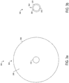
- FIG. 3 illustrates a movable structure 300 that according to one example embodiment may correspond to movable structure 108.
- the movable structure may include a base 302 and a canopy 304 extending continuously, circumferentially around the base.
- the canopy may include a flexible material such as a fabric supported by a frame or other support structures, which in one example may be interwoven into the flexible material.
- the canopy includes a major surface 306 and a minor surface 308, with the major surface having a greater surface area than the minor surface.
- the movable structure may have a first configuration in which the canopy is arranged with its major surface facing the direction of current flow.
- the movable structure may reconfigure to a second configuration in which its canopy is arranged with its minor surface facing the direction of current flow.
- the canopy may be collapsible about the base in a manner similar to an umbrella, as shown in FIG. 3b .
- the movable structure may then have this second configuration during the recovery phase.
- FIG. 4 illustrates a movable structure 400 that according to another example embodiment may correspond to movable structure 108.
- the movable structure may include a base 402 and a number of (one or more) fins 404 extending circumferentially around the base.
- Each of the fins includes a major surface 406 and a minor surface 408, with the major surface having a greater surface area than the minor surface.
- the movable structure may have a first configuration in which its fins are arranged with their major surfaces facing the direction of current flow.
- the movable structure may reconfigure to a second configuration in which its fins are arranged with their minor surfaces facing the direction of current flow.
- the fins may each rotate 90° relative to the base, as shown in FIG. 4b .
- the moveable structure may include an even number of fins that alternately rotate +90° and -90° relative to the base, which in various instances, may mitigate spin that may otherwise be caused by rotation of the fins.
- the fins may therefore be rotatable relative to the base to reconfigure the movable structure between the first and second configurations.
- the movable structure may then have this second configuration during the recovery phase in which the movable structure moves back toward the support structure.
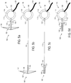
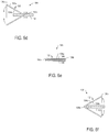
- FIG. 5 illustrates a top view of the system 100 through various stages of a power cycle.
- the movable structure 108 is in a first configuration with a greater surface area normal to the flow of underwater current as the movable structure moves away from the support structure 106, as shown in FIGS. 5a and 5b .
- the movable structure reconfigures to a second configuration with a lesser surface area normal to the flow of underwater current.
- the movable structure may then be pulled back to the support structure during the recovery phase, as shown in FIGS. 5c and 5d .
- FIG. 6 illustrates a top view of the movable structure 108 through various stages of a power cycle.
- the movable structure includes a canopy 132 or one or more fins extending from a base 130.
- the canopy may include first and second opposing major surfaces 134a, 134b joined by first and second opposing minor surfaces 136a, 136b.
- FIG. 6a illustrates the movable structure during the power generation phase in which the movable structure has a first configuration. In the first configuration, the canopy may be arranged with its first major surface 134a facing the direction of current flow (shown by the arrow).
- first minor surface 136a may be extended out from the base by the first and second major surfaces, and the second minor surface 136b may be held against or proximate the base of the movable structure.
- the movable structure may include a latch to at least partially hold the movable structure in the first configuration.
- the movable structure may include a collar about its base that may slidably engage a latch on the base holding the canopy or rather its second minor surface in place.
- the movable structure 108 may be engaged to reconfigure itself from the first configuration to a second configuration for the recovery phase of the power cycle.
- current flow may move the collar to engage the latch at the base 130 of the movable structure to free the second minor surface 136b of the canopy 132.
- continued current flow may push the first minor surface 136a in the direction of current flow and then downward toward the base, which may appear similar to turning an umbrella inside out.
- the second minor surface may slidably engage the base, and may move along the base opposite the direction of current flow as the first minor surface moves downward toward the base.
- This movement may continue until the canopy lies approximately against the base, at which point the movable structure is in the second configuration, and the second minor surface of its canopy faces the direction of current flow, as shown in FIG. 6e .
- the first minor surface may be latched against or proximate the base of the movable structure, similar to the second minor surface before.
- Reconfiguration of the movable structure 108 may occur at the end of the power generation phase, beginning of the recovery phase, or between or across the power generation and recovery phases.
- the movable structure may again reconfigure itself from the second configuration to the first configuration.
- the guide structure 122 of the support structure 106 may include an angled surface. As the movable structure is pulled in toward the support structure, the movable structure may engage the guide structure and its angled surface may at least partially wedge between the canopy 132 and base 130. This may cause the second minor surface 136 of the canopy to begin to pivot out and away from the base, as shown in FIG. 6f . The direction of current flow, then, may push the canopy outward and back to the first configuration (see FIG. 6a ).
- This reconfiguration may occur at the end of the recovery phase, beginning of the power generation phase, or between or across the recovery and power generation phases. The power cycle may then begin again.
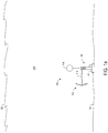
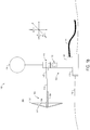
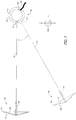
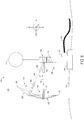
- the movable structure 106 may have three, four or more degrees of freedom. Reference is again made to FIG. 1 , and now more particularly to FIGS. 7 and 8 .
- the system includes a z-axis generally perpendicular to the surface 102 of the body of water 104, and x- and y-axes generally parallel to the surface.
- Current flow in the body of water may generally have either or both of an x-axis component or y-axis component. But in various instances, current may flow upward or downward toward or away from the surface, with current flow thereby adding a z-axis component.
- the movable structure 108 may be rotatable about its base 130 and linearly movable away from or toward the support structure 106.
- the swivel structure 124 of the support structure may additionally permit movement of the movable structure about the z-axis, as shown in FIG. 7 .
- These three-degrees of freedom may permit the movable structure to move with an x-axis component and y-axis component of current flow.
- the guide structure 122 of the support structure may be a pivotable guide structure, which may permit movement of the movable structure about the y-axis. This additional degree of freedom may permit the movable structure to move with a z-axis component of current flow.
- the movable structure may therefore have additional degrees of freedom that may permit the movable structure to move with current flow, which may not always be in the same direction.
- the system 100 may be deployable as a pre-fabricated module for easy set up and use, such as for remote operations or supplemental power to extend missions.
- the system may be employed in groups as a "farm" with associated power cables 126 collectively feeding power to a storage or transmission system.
- the system may be employed in a forward operating base (FOB) or other installation or facility that may require power.
- FOB forward operating base
- the system may provide a smaller footprint than current water-based energy production systems, and may do so with more environmental advantages, less moving/rotating parts, complexity, noise reduction and the like.
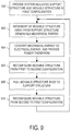
- the method includes deploying in a body of fluid (e.g., body of water 104 ), a system 100 including a support structure 106 connected to a movable structure 108, or otherwise providing such a system deployed in a body of fluid.
- a body of fluid e.g., body of water 104
- the system may be deployed underneath a surface (e.g., surface 102 ) of the body of fluid.
- the system may further include a buoy 114 to which the support structure is tethered, with the buoy being configured to hold the support structure upright when deployed.
- the method includes generating mechanical energy by the movable structure 108 in reaction to fluid motion acting on the movable structure during a power generation phase of a power cycle, with the movable structure having three or more degrees of freedom.
- generating the mechanical energy includes movement of the movable structure away from the support structure 106, as shown in block 902, with the movable structure being connected to the support structure by a cable 118 that allows the respective movement.
- the method also includes converting the mechanical energy to electrical energy and providing electric power from the electrical energy, as shown in block 904.
- the method may further include reconfiguring the movable structure 108 from a first configuration and to a second, different configuration for a recovery phase of the power cycle, as shown in block 906.
- the movable structure in the first configuration having a greater surface area normal to the flow of fluid than the movable structure in the second configuration.
- the method may include pulling the movable structure back to the support structure 106 by the cable during the recovery phase, as shown in block 908.
- the movable structure may be again reconfigured from the second configuration back to the first configuration, as shown in block 910. And another power cycle may begin anew with movement of the movable structure away from the support structure.
- the body of fluid has a surface generally perpendicular to a first axis and parallel with second and third axes of a Cartesian coordinate system, and in which the fluid motion has one or more of a first-axis component, second-axis component or third-axis component.
- generating the mechanical energy may include movement of the movable structure 108 with the second-axis component and third-axis component of the fluid motion, and away from the support structure 106. Additionally or alternatively, for example, generating the mechanical energy may include movement of the movable structure with the first-axis component of the fluid motion.
- the movable structure 108 includes a base 130 and a canopy 132 or one or more fins coupled to and extending from the base.
- the canopy includes a major surface 134 and a minor surface 136, with the major surface having a greater surface area than the minor surface.
- the canopy may be arranged with its major surface facing a direction of fluid motion in the first configuration. Reconfiguring the movable structure, then, may include reconfiguring the canopy such that its minor surface faces the direction of fluid motion in the second configuration.
- the movable structure 300 includes a canopy 304 that extends circumferentially around the base 302, and reconfiguring the canopy includes collapsing the canopy about the base (see FIG. 3 ).
- the movable structure 400 includes a plurality of fins 404 extending circumferentially around the base 402, and reconfiguring the fin includes rotating each fin about the base (see FIG. 4 ).
Landscapes
- Engineering & Computer Science (AREA)
- Chemical & Material Sciences (AREA)
- Combustion & Propulsion (AREA)
- Mechanical Engineering (AREA)
- General Engineering & Computer Science (AREA)
- Power Engineering (AREA)
- Life Sciences & Earth Sciences (AREA)
- General Life Sciences & Earth Sciences (AREA)
- Oceanography (AREA)
- Other Liquid Machine Or Engine Such As Wave Power Use (AREA)
Claims (9)
- System zum Konvertieren von Fluidbewegung in elektrische Leistung, wobei das System in einem Fluidkörper derart einsetzbar ist, dass der Fluidkörper eine Fläche im Allgemeinen senkrecht zu einer ersten Achse und parallel zu einer zweiten und dritten Achse eines kartesischen Koordinatensystems hat, und derart, dass die Fluidbewegung eine oder mehrere von einer ersten Achsenkomponente, zweiten Achsenkomponente oder dritten Achsenkomponente hat, und das System Folgendes aufweist:eine Tragstruktur (106), die eine Generatoranordnung (120, 200) aufweist, die konfiguriert ist, um mechanische Energie in elektrische Energie zu konvertieren und elektrische Leistung aus der elektrischen Energie bereitzustellen, eine Schwenkstruktur, die konfiguriert ist, um eine Bewegung der bewegbaren Struktur (108, 300, 400) mit der zweiten Achsenkomponente und dritten Achsenkomponente der Fluidbewegung zu erlauben, und eine schwenkbare Führungsstruktur, die konfiguriert ist, um eine Bewegung der bewegbaren Struktur (108) mit der ersten Achsenkomponente der Fluidbewegung zu erlauben, undeine bewegbare Struktur (108, 300, 400), die mit der Tragstruktur (106) verbunden und konfiguriert ist, um mechanische Energie zur Konvertierung durch die Generatoranordnung (120, 200) während einer Leistungserzeugungsphase eines Leistungszyklus zu erzeugen, in der die Fluidbewegung auf die bewegbare Struktur (108, 300, 400) wirkt, wobei die bewegbare Struktur (108, 300, 400) drei oder mehr Freiheitsgrade hat,wobei die bewegbare Struktur (108, 300, 400) eine erste Konfiguration während der Leistungserzeugungsphase und eine zweite, andere Konfiguration während einer Erholungsphase des Leistungszyklus hat, wobei die bewegbare Struktur (108, 300, 400) in der ersten Konfiguration einen größeren Flächenbereich hat, der normal zu einem Fluidstrom ist, als die bewegbare Struktur (108, 300, 400) in der zweiten Konfiguration.
- System nach Anspruch 1, wobei die bewegbare Struktur (108, 300, 400) Folgendes aufweist:eine Basis (130, 302, 402) undeine Überdachung (132, 304), die mit der Basis (130, 302, 402) verbunden ist und sich davon erstreckt, wobei die Überdachung (132, 304) eine Hauptfläche (134, 306) und eine Nebenfläche (136, 308) aufweist, wobei die Hauptfläche (134, 306) einen größeren Flächenbereich hat als die Nebenfläche (136, 308),wobei die Überdachung (132, 304) mit ihrer Hauptfläche (134, 306) in der ersten Konfiguration einer Fluidbewegungsrichtung zugewandt angeordnet ist und mit ihrer Nebenfläche (136, 308) in der zweiten Konfiguration der Fluidbewegungsrichtung zugewandt angeordnet ist.
- System nach Anspruch 1, wobei die bewegbare Struktur (108, 300, 400) Folgendes aufweist:eine Basis (130, 302, 402) undeine Anzahl von Flossen (404), die mit der Basis (130, 302, 402) verbunden sind und sich davon erstrecken, wobei jede Flosse eine Hauptfläche (406) und eine Nebenfläche (408) aufweist, wobei die Hauptfläche (406) einen größeren Flächenbereich hat als die Nebenfläche (408),wobei jede Flosse mit ihrer Hauptfläche (406) in der ersten Konfiguration einer Fluidbewegungsrichtung zugewandt angeordnet ist und mit ihrer Nebenfläche (408) in der zweiten Konfiguration der Fluidbewegungsrichtung zugewandt angeordnet ist.
- System nach einem der Ansprüche 1 -3, das unterhalb einer Fläche des Fluidkörpers einsetzbar ist, wobei das System ferner Folgendes aufweist:
eine Boje, an die die Tragstruktur (106) angebunden ist, wobei die Boje konfiguriert ist, um die Tragstruktur (106) aufrecht zu halten, wenn sie eingesetzt wird. - Verfahren zum Konvertieren von Fluidbewegung in elektrische Leistung, das Folgendes aufweist:Bereitstellen eines Systems, das eine bewegbare Struktur (108, 300, 400) aufweist, die mit einer Tragstruktur (106) verbunden ist, wobei das System in einem Fluidkörper eingesetzt wird, wobei der Fluidkörper eine Fläche im Allgemeinen senkrecht zu einer ersten Achse und parallel zu einer zweiten und dritten Achse eines kartesischen Koordinatensystems hat, und in dem die Fluidbewegung eine oder mehrere von einer ersten Achsenkomponente, zweiten Achsenkomponente oder dritten Achsenkomponente hat, und wobei die Tragstruktur (106) Folgendes beinhaltet:eine Generatoranordnung (120, 200), die konfiguriert ist, um mechanische Energie in elektrische Energie zu konvertieren und elektrische Leistung aus der elektrischen Energie bereitzustellen,eine Schwenkstruktur, die konfiguriert ist, um eine Bewegung der bewegbaren Struktur (108, 300, 400) mit der zweiten Achsenkomponente und dritten Achsenkomponente der Fluidbewegung zu erlauben, undeine schwenkbare Führungsstruktur, die konfiguriert ist, um eine Bewegung der bewegbaren Struktur (108) mit der ersten Achsenkomponente der Fluidbewegung zu erlauben,Erzeugen von mechanischer Energie durch die bewegbare Struktur (108, 300, 400) zur Konvertierung durch die Generatoranordnung (120, 200) als Reaktion auf eine Fluidbewegung, die auf die bewegbare Struktur (108, 300, 400) während einer Leistungserzeugungsphase eines Leistungszyklus wirkt, wobei die bewegbare Struktur (108, 300, 400) drei oder mehr Freiheitsgrade hat, wobei ein Erzeugen der mechanischen Energie eine Bewegung der bewegbaren Struktur (108) mit der ersten Achsenkomponente, zweiten Achsenkomponente und dritten Achsenkomponente der Fluidbewegung und weg von der Tragstruktur (106) aufweist,Konvertieren durch die Generatoranordnung (120, 200) der mechanischen Energie in elektrische Energie und Bereitstellen von elektrischer Leistung aus der elektrischen Energie undRekonfigurieren der bewegbaren Struktur (108, 300, 400) von einer ersten Konfiguration in eine zweite, andere Konfiguration für eine Erholungsphase des Leistungszyklus, wobei die bewegbare Struktur in der ersten Konfiguration einen größeren Flächenbereich hat, der normal zu einem Fluidstrom ist, als die bewegbare Struktur (108, 300, 400) in der zweiten Konfiguration.
- Verfahren nach Anspruch 5, das ferner ein Zurückziehen der bewegbaren Struktur (108, 300, 400) zu der Tragstruktur (106) durch ein Kabel während der Erholungsphase aufweist.
- Verfahren nach einem der Ansprüche 5-6, wobei die bewegbare Struktur (108, 300, 400) Folgendes aufweist:eine Basis (130, 302, 402) undeine Überdachung (132, 304), die mit der Basis (130, 302, 402) verbunden ist und sich davon erstreckt, wobei die , (132, 304) eine Hauptfläche (134, 306) und eine Nebenfläche (136, 308) aufweist, wobei die Hauptfläche (134, 306) einen größeren Flächenbereich hat als die Nebenfläche (136, 308), wobei die Überdachung (132, 304) mit ihrer Hauptfläche (134, 306) in der ersten Konfiguration einer Fluidbewegungsrichtung zugewandt angeordnet ist,wobei ein Rekonfigurieren der bewegbaren Struktur (108) ein derartiges Rekonfigurieren der Überdachung (132, 304) aufweist, dass ihre Nebenfläche (136, 308) in der zweiten Konfiguration der Fluidbewegungsrichtung zugewandt ist.
- Verfahren nach einem der Ansprüche 5-6, wobei die bewegbare Struktur (108, 300, 400) Folgendes aufweist:eine Basis (130, 302, 402) undeine Anzahl von Flossen (404), die mit der Basis (130, 302, 402) verbunden sind und sich davon erstrecken, wobei jede Flosse eine Hauptfläche (406) und eine Nebenfläche (408) aufweist, wobei die Hauptfläche (406) einen größeren Flächenbereich hat als die Nebenfläche (408) und jede Flosse mit ihrer Hauptfläche (406) in der ersten Konfiguration einer Fluidbewegungsrichtung zugewandt angeordnet ist,wobei ein Rekonfigurieren der bewegbaren Struktur (108, 300, 400) ein derartiges Rekonfigurieren jeder Flosse aufweist, dass ihre Nebenfläche (408) in der zweiten Konfiguration der Fluidbewegungsrichtung zugewandt ist.
- Verfahren nach Anspruch 8, wobei sich die Anzahl von Flossen (404) umlaufend um die Basis (130, 302, 402) erstreckt und wobei ein Rekonfigurieren jeder Flosse ein Drehen jeder Flosse um die Basis (130, 302, 402) aufweist.
Applications Claiming Priority (2)
| Application Number | Priority Date | Filing Date | Title |
|---|---|---|---|
| US13/468,640 US10036365B2 (en) | 2012-05-10 | 2012-05-10 | System and method for converting fluid motion into electrical power |
| PCT/US2013/030262 WO2013169341A2 (en) | 2012-05-10 | 2013-03-11 | System and method for converting fluid motion into electrical power |
Publications (2)
| Publication Number | Publication Date |
|---|---|
| EP2867522A2 EP2867522A2 (de) | 2015-05-06 |
| EP2867522B1 true EP2867522B1 (de) | 2018-11-07 |
Family
ID=48048183
Family Applications (1)
| Application Number | Title | Priority Date | Filing Date |
|---|---|---|---|
| EP13714379.8A Active EP2867522B1 (de) | 2012-05-10 | 2013-03-11 | System und verfahren zur umwandlung von fluidbewegung in elektrische energie |
Country Status (4)
| Country | Link |
|---|---|
| US (2) | US10036365B2 (de) |
| EP (1) | EP2867522B1 (de) |
| CN (1) | CN104321526B (de) |
| WO (1) | WO2013169341A2 (de) |
Families Citing this family (6)
| Publication number | Priority date | Publication date | Assignee | Title |
|---|---|---|---|---|
| US20140001761A1 (en) * | 2011-09-19 | 2014-01-02 | Lisa Mauck Weiland | Adaptive hydrokinetic energy harvesting |
| KR20180004188A (ko) * | 2015-05-01 | 2018-01-10 | 빅 문 파워, 인크. | 조력 에너지 변환 및 발전용 시스템 및 방법 |
| PH12017550130B1 (en) * | 2015-05-18 | 2022-08-19 | Seaqurrent Holding B V | Method and system for energy conversion from a flow of fluid |
| PL417271A1 (pl) * | 2016-05-20 | 2017-12-04 | Adam Bednarczyk | Żaglowa siłownia wiatrowa |
| US10458385B2 (en) | 2017-04-28 | 2019-10-29 | Big Moon Power, Inc. | Systems and methods for tidal energy conversion and electrical power generation using a rotatable drag panel |
| AU2018411293B2 (en) * | 2018-02-27 | 2023-08-17 | Halliburton Energy Services, Inc. | Downhole check valve assembly with a ratchet mechanism |
Family Cites Families (17)
| Publication number | Priority date | Publication date | Assignee | Title |
|---|---|---|---|---|
| US2414480A (en) | 1945-02-07 | 1947-01-21 | Morrill Ferdinand Gordon | Underwater kite |
| DE2905157A1 (de) * | 1978-05-12 | 1980-08-21 | Martin Schatta | Wasserkraftwerk |
| DE3029523C2 (de) | 1980-08-04 | 1984-11-22 | Christensen, Inc., Salt Lake City, Utah | Generator zur Energieversorgung von innerhalb eines Bohrloches angeordneten Verbrauchern |
| US6555931B2 (en) * | 2000-09-20 | 2003-04-29 | Omnific International, Ltd. | Renewable energy systems using long-stroke open-channel reciprocating engines |
| US6955049B2 (en) * | 2003-05-29 | 2005-10-18 | Krouse Wayne F | Machine and system for power generation through movement of water |
| US6956300B2 (en) * | 2003-08-04 | 2005-10-18 | Andrew Roman Gizara | Gimbal-mounted hydroelectric turbine |
| GB0613243D0 (en) * | 2005-09-22 | 2006-08-09 | Pattinson 5 Ltd | Kitepower generator |
| ES2610129T3 (es) | 2006-02-02 | 2017-04-26 | Minesto Ab | Una planta sumergible |
| US20110266805A1 (en) | 2006-02-02 | 2011-11-03 | Minesto Ab | Submersible plant |
| FR2923554B1 (fr) * | 2007-11-09 | 2009-12-18 | Sdmi | Dispositif de recuperation d'energie base sur le deplacement de navettes immergees derivant dans un courant marin ou fluvial et comportant des elements deployables |
| US20090212562A1 (en) | 2008-02-27 | 2009-08-27 | The Boeing Company | Method and apparatus for tidal power generation |
| US20100276934A1 (en) | 2009-04-29 | 2010-11-04 | Green Hydropower Incorporated | System for generating electric power from fluid current |
| US8405244B2 (en) | 2009-05-04 | 2013-03-26 | Skywind, Inc. | System and method for umbrella power generation |
| US8456026B2 (en) | 2009-06-01 | 2013-06-04 | The Boeing Company | Power generator |
| GB2480694B (en) * | 2010-05-28 | 2014-06-25 | Robert William Wallace Burden | Energy extraction from the ocean depths |
| US20120086210A1 (en) * | 2010-10-07 | 2012-04-12 | Dennis John Gray | Device for Extracting Energy from Moving Air or Moving Water |
| CN202140248U (zh) * | 2011-06-08 | 2012-02-08 | 广东高空风能技术有限公司 | 伞型风力装置及风能动力系统 |
-
2012
- 2012-05-10 US US13/468,640 patent/US10036365B2/en active Active
-
2013
- 2013-03-11 CN CN201380019235.9A patent/CN104321526B/zh active Active
- 2013-03-11 EP EP13714379.8A patent/EP2867522B1/de active Active
- 2013-03-11 WO PCT/US2013/030262 patent/WO2013169341A2/en not_active Ceased
-
2018
- 2018-07-02 US US16/025,595 patent/US10519925B2/en active Active
Non-Patent Citations (1)
| Title |
|---|
| None * |
Also Published As
| Publication number | Publication date |
|---|---|
| CN104321526A (zh) | 2015-01-28 |
| US20180313323A1 (en) | 2018-11-01 |
| WO2013169341A2 (en) | 2013-11-14 |
| US10036365B2 (en) | 2018-07-31 |
| EP2867522A2 (de) | 2015-05-06 |
| CN104321526B (zh) | 2017-06-06 |
| WO2013169341A3 (en) | 2014-02-20 |
| US10519925B2 (en) | 2019-12-31 |
| US20130300122A1 (en) | 2013-11-14 |
Similar Documents
| Publication | Publication Date | Title |
|---|---|---|
| US10519925B2 (en) | System and method for converting fluid motion into electrical power | |
| US20220307459A1 (en) | Self-propelled buoyant energy converter and method for deploying same | |
| US11242840B2 (en) | Ocean water power-generator | |
| CN102782309B (zh) | 海洋发电设备 | |
| JP5139439B2 (ja) | 完全水没型波エネルギー変換装置 | |
| US20090212562A1 (en) | Method and apparatus for tidal power generation | |
| US20120211988A1 (en) | Submersible electric power generator system | |
| EP3240951B1 (de) | System zur energiegewinnung aus einer beweglichen masse | |
| CN114555933B (zh) | 驱动组件 | |
| EP3665383B1 (de) | Antriebsanordnung | |
| CN111094739A (zh) | 波浪动力产能器 | |
| WO2021222221A1 (en) | Oscillating tension wave energy converter | |
| US8851837B2 (en) | Apparatus and method for energy extraction | |
| WO2013019214A1 (en) | Submerged wave energy converter | |
| GB2424674A (en) | Generating electricity from flowing water, eg tidal currents | |
| CN110486213A (zh) | 多波向式波浪发电系统 | |
| TW201938903A (zh) | 多波向式波浪發電系統 |
Legal Events
| Date | Code | Title | Description |
|---|---|---|---|
| PUAI | Public reference made under article 153(3) epc to a published international application that has entered the european phase |
Free format text: ORIGINAL CODE: 0009012 |
|
| 17P | Request for examination filed |
Effective date: 20141204 |
|
| AK | Designated contracting states |
Kind code of ref document: A2 Designated state(s): AL AT BE BG CH CY CZ DE DK EE ES FI FR GB GR HR HU IE IS IT LI LT LU LV MC MK MT NL NO PL PT RO RS SE SI SK SM TR |
|
| AX | Request for extension of the european patent |
Extension state: BA ME |
|
| DAX | Request for extension of the european patent (deleted) | ||
| STAA | Information on the status of an ep patent application or granted ep patent |
Free format text: STATUS: EXAMINATION IS IN PROGRESS |
|
| 17Q | First examination report despatched |
Effective date: 20170127 |
|
| GRAP | Despatch of communication of intention to grant a patent |
Free format text: ORIGINAL CODE: EPIDOSNIGR1 |
|
| STAA | Information on the status of an ep patent application or granted ep patent |
Free format text: STATUS: GRANT OF PATENT IS INTENDED |
|
| INTG | Intention to grant announced |
Effective date: 20180508 |
|
| GRAJ | Information related to disapproval of communication of intention to grant by the applicant or resumption of examination proceedings by the epo deleted |
Free format text: ORIGINAL CODE: EPIDOSDIGR1 |
|
| STAA | Information on the status of an ep patent application or granted ep patent |
Free format text: STATUS: EXAMINATION IS IN PROGRESS |
|
| GRAR | Information related to intention to grant a patent recorded |
Free format text: ORIGINAL CODE: EPIDOSNIGR71 |
|
| GRAS | Grant fee paid |
Free format text: ORIGINAL CODE: EPIDOSNIGR3 |
|
| STAA | Information on the status of an ep patent application or granted ep patent |
Free format text: STATUS: GRANT OF PATENT IS INTENDED |
|
| GRAA | (expected) grant |
Free format text: ORIGINAL CODE: 0009210 |
|
| STAA | Information on the status of an ep patent application or granted ep patent |
Free format text: STATUS: THE PATENT HAS BEEN GRANTED |
|
| INTC | Intention to grant announced (deleted) | ||
| AK | Designated contracting states |
Kind code of ref document: B1 Designated state(s): AL AT BE BG CH CY CZ DE DK EE ES FI FR GB GR HR HU IE IS IT LI LT LU LV MC MK MT NL NO PL PT RO RS SE SI SK SM TR |
|
| INTG | Intention to grant announced |
Effective date: 20181001 |
|
| REG | Reference to a national code |
Ref country code: GB Ref legal event code: FG4D |
|
| REG | Reference to a national code |
Ref country code: CH Ref legal event code: EP Ref country code: AT Ref legal event code: REF Ref document number: 1062350 Country of ref document: AT Kind code of ref document: T Effective date: 20181115 |
|
| REG | Reference to a national code |
Ref country code: IE Ref legal event code: FG4D |
|
| REG | Reference to a national code |
Ref country code: DE Ref legal event code: R096 Ref document number: 602013046270 Country of ref document: DE |
|
| REG | Reference to a national code |
Ref country code: NL Ref legal event code: MP Effective date: 20181107 |
|
| REG | Reference to a national code |
Ref country code: LT Ref legal event code: MG4D |
|
| REG | Reference to a national code |
Ref country code: AT Ref legal event code: MK05 Ref document number: 1062350 Country of ref document: AT Kind code of ref document: T Effective date: 20181107 |
|
| PG25 | Lapsed in a contracting state [announced via postgrant information from national office to epo] |
Ref country code: AT Free format text: LAPSE BECAUSE OF FAILURE TO SUBMIT A TRANSLATION OF THE DESCRIPTION OR TO PAY THE FEE WITHIN THE PRESCRIBED TIME-LIMIT Effective date: 20181107 Ref country code: HR Free format text: LAPSE BECAUSE OF FAILURE TO SUBMIT A TRANSLATION OF THE DESCRIPTION OR TO PAY THE FEE WITHIN THE PRESCRIBED TIME-LIMIT Effective date: 20181107 Ref country code: BG Free format text: LAPSE BECAUSE OF FAILURE TO SUBMIT A TRANSLATION OF THE DESCRIPTION OR TO PAY THE FEE WITHIN THE PRESCRIBED TIME-LIMIT Effective date: 20190207 Ref country code: ES Free format text: LAPSE BECAUSE OF FAILURE TO SUBMIT A TRANSLATION OF THE DESCRIPTION OR TO PAY THE FEE WITHIN THE PRESCRIBED TIME-LIMIT Effective date: 20181107 Ref country code: LT Free format text: LAPSE BECAUSE OF FAILURE TO SUBMIT A TRANSLATION OF THE DESCRIPTION OR TO PAY THE FEE WITHIN THE PRESCRIBED TIME-LIMIT Effective date: 20181107 Ref country code: NO Free format text: LAPSE BECAUSE OF FAILURE TO SUBMIT A TRANSLATION OF THE DESCRIPTION OR TO PAY THE FEE WITHIN THE PRESCRIBED TIME-LIMIT Effective date: 20190207 Ref country code: IS Free format text: LAPSE BECAUSE OF FAILURE TO SUBMIT A TRANSLATION OF THE DESCRIPTION OR TO PAY THE FEE WITHIN THE PRESCRIBED TIME-LIMIT Effective date: 20190307 Ref country code: FI Free format text: LAPSE BECAUSE OF FAILURE TO SUBMIT A TRANSLATION OF THE DESCRIPTION OR TO PAY THE FEE WITHIN THE PRESCRIBED TIME-LIMIT Effective date: 20181107 Ref country code: LV Free format text: LAPSE BECAUSE OF FAILURE TO SUBMIT A TRANSLATION OF THE DESCRIPTION OR TO PAY THE FEE WITHIN THE PRESCRIBED TIME-LIMIT Effective date: 20181107 |
|
| PG25 | Lapsed in a contracting state [announced via postgrant information from national office to epo] |
Ref country code: GR Free format text: LAPSE BECAUSE OF FAILURE TO SUBMIT A TRANSLATION OF THE DESCRIPTION OR TO PAY THE FEE WITHIN THE PRESCRIBED TIME-LIMIT Effective date: 20190208 Ref country code: RS Free format text: LAPSE BECAUSE OF FAILURE TO SUBMIT A TRANSLATION OF THE DESCRIPTION OR TO PAY THE FEE WITHIN THE PRESCRIBED TIME-LIMIT Effective date: 20181107 Ref country code: AL Free format text: LAPSE BECAUSE OF FAILURE TO SUBMIT A TRANSLATION OF THE DESCRIPTION OR TO PAY THE FEE WITHIN THE PRESCRIBED TIME-LIMIT Effective date: 20181107 Ref country code: SE Free format text: LAPSE BECAUSE OF FAILURE TO SUBMIT A TRANSLATION OF THE DESCRIPTION OR TO PAY THE FEE WITHIN THE PRESCRIBED TIME-LIMIT Effective date: 20181107 Ref country code: NL Free format text: LAPSE BECAUSE OF FAILURE TO SUBMIT A TRANSLATION OF THE DESCRIPTION OR TO PAY THE FEE WITHIN THE PRESCRIBED TIME-LIMIT Effective date: 20181107 Ref country code: PT Free format text: LAPSE BECAUSE OF FAILURE TO SUBMIT A TRANSLATION OF THE DESCRIPTION OR TO PAY THE FEE WITHIN THE PRESCRIBED TIME-LIMIT Effective date: 20190307 |
|
| PG25 | Lapsed in a contracting state [announced via postgrant information from national office to epo] |
Ref country code: DK Free format text: LAPSE BECAUSE OF FAILURE TO SUBMIT A TRANSLATION OF THE DESCRIPTION OR TO PAY THE FEE WITHIN THE PRESCRIBED TIME-LIMIT Effective date: 20181107 Ref country code: PL Free format text: LAPSE BECAUSE OF FAILURE TO SUBMIT A TRANSLATION OF THE DESCRIPTION OR TO PAY THE FEE WITHIN THE PRESCRIBED TIME-LIMIT Effective date: 20181107 Ref country code: CZ Free format text: LAPSE BECAUSE OF FAILURE TO SUBMIT A TRANSLATION OF THE DESCRIPTION OR TO PAY THE FEE WITHIN THE PRESCRIBED TIME-LIMIT Effective date: 20181107 Ref country code: IT Free format text: LAPSE BECAUSE OF FAILURE TO SUBMIT A TRANSLATION OF THE DESCRIPTION OR TO PAY THE FEE WITHIN THE PRESCRIBED TIME-LIMIT Effective date: 20181107 |
|
| REG | Reference to a national code |
Ref country code: DE Ref legal event code: R097 Ref document number: 602013046270 Country of ref document: DE |
|
| PG25 | Lapsed in a contracting state [announced via postgrant information from national office to epo] |
Ref country code: RO Free format text: LAPSE BECAUSE OF FAILURE TO SUBMIT A TRANSLATION OF THE DESCRIPTION OR TO PAY THE FEE WITHIN THE PRESCRIBED TIME-LIMIT Effective date: 20181107 Ref country code: EE Free format text: LAPSE BECAUSE OF FAILURE TO SUBMIT A TRANSLATION OF THE DESCRIPTION OR TO PAY THE FEE WITHIN THE PRESCRIBED TIME-LIMIT Effective date: 20181107 Ref country code: SM Free format text: LAPSE BECAUSE OF FAILURE TO SUBMIT A TRANSLATION OF THE DESCRIPTION OR TO PAY THE FEE WITHIN THE PRESCRIBED TIME-LIMIT Effective date: 20181107 Ref country code: SK Free format text: LAPSE BECAUSE OF FAILURE TO SUBMIT A TRANSLATION OF THE DESCRIPTION OR TO PAY THE FEE WITHIN THE PRESCRIBED TIME-LIMIT Effective date: 20181107 |
|
| PLBE | No opposition filed within time limit |
Free format text: ORIGINAL CODE: 0009261 |
|
| STAA | Information on the status of an ep patent application or granted ep patent |
Free format text: STATUS: NO OPPOSITION FILED WITHIN TIME LIMIT |
|
| 26N | No opposition filed |
Effective date: 20190808 |
|
| PG25 | Lapsed in a contracting state [announced via postgrant information from national office to epo] |
Ref country code: SI Free format text: LAPSE BECAUSE OF FAILURE TO SUBMIT A TRANSLATION OF THE DESCRIPTION OR TO PAY THE FEE WITHIN THE PRESCRIBED TIME-LIMIT Effective date: 20181107 Ref country code: MC Free format text: LAPSE BECAUSE OF FAILURE TO SUBMIT A TRANSLATION OF THE DESCRIPTION OR TO PAY THE FEE WITHIN THE PRESCRIBED TIME-LIMIT Effective date: 20181107 |
|
| REG | Reference to a national code |
Ref country code: CH Ref legal event code: PL |
|
| PG25 | Lapsed in a contracting state [announced via postgrant information from national office to epo] |
Ref country code: LU Free format text: LAPSE BECAUSE OF NON-PAYMENT OF DUE FEES Effective date: 20190311 |
|
| REG | Reference to a national code |
Ref country code: BE Ref legal event code: MM Effective date: 20190331 |
|
| PG25 | Lapsed in a contracting state [announced via postgrant information from national office to epo] |
Ref country code: LI Free format text: LAPSE BECAUSE OF NON-PAYMENT OF DUE FEES Effective date: 20190331 Ref country code: IE Free format text: LAPSE BECAUSE OF NON-PAYMENT OF DUE FEES Effective date: 20190311 Ref country code: CH Free format text: LAPSE BECAUSE OF NON-PAYMENT OF DUE FEES Effective date: 20190331 |
|
| PG25 | Lapsed in a contracting state [announced via postgrant information from national office to epo] |
Ref country code: BE Free format text: LAPSE BECAUSE OF NON-PAYMENT OF DUE FEES Effective date: 20190331 |
|
| PG25 | Lapsed in a contracting state [announced via postgrant information from national office to epo] |
Ref country code: TR Free format text: LAPSE BECAUSE OF FAILURE TO SUBMIT A TRANSLATION OF THE DESCRIPTION OR TO PAY THE FEE WITHIN THE PRESCRIBED TIME-LIMIT Effective date: 20181107 |
|
| PG25 | Lapsed in a contracting state [announced via postgrant information from national office to epo] |
Ref country code: MT Free format text: LAPSE BECAUSE OF NON-PAYMENT OF DUE FEES Effective date: 20190311 |
|
| PG25 | Lapsed in a contracting state [announced via postgrant information from national office to epo] |
Ref country code: CY Free format text: LAPSE BECAUSE OF FAILURE TO SUBMIT A TRANSLATION OF THE DESCRIPTION OR TO PAY THE FEE WITHIN THE PRESCRIBED TIME-LIMIT Effective date: 20181107 |
|
| PG25 | Lapsed in a contracting state [announced via postgrant information from national office to epo] |
Ref country code: HU Free format text: LAPSE BECAUSE OF FAILURE TO SUBMIT A TRANSLATION OF THE DESCRIPTION OR TO PAY THE FEE WITHIN THE PRESCRIBED TIME-LIMIT; INVALID AB INITIO Effective date: 20130311 |
|
| PG25 | Lapsed in a contracting state [announced via postgrant information from national office to epo] |
Ref country code: MK Free format text: LAPSE BECAUSE OF FAILURE TO SUBMIT A TRANSLATION OF THE DESCRIPTION OR TO PAY THE FEE WITHIN THE PRESCRIBED TIME-LIMIT Effective date: 20181107 |
|
| P01 | Opt-out of the competence of the unified patent court (upc) registered |
Effective date: 20230516 |
|
| PGFP | Annual fee paid to national office [announced via postgrant information from national office to epo] |
Ref country code: GB Payment date: 20260327 Year of fee payment: 14 |
|
| PGFP | Annual fee paid to national office [announced via postgrant information from national office to epo] |
Ref country code: DE Payment date: 20260327 Year of fee payment: 14 |
|
| PGFP | Annual fee paid to national office [announced via postgrant information from national office to epo] |
Ref country code: FR Payment date: 20260325 Year of fee payment: 14 |