EP2866552B1 - Lame arracheuse pour machine forestière - Google Patents
Lame arracheuse pour machine forestière Download PDFInfo
- Publication number
- EP2866552B1 EP2866552B1 EP13809097.2A EP13809097A EP2866552B1 EP 2866552 B1 EP2866552 B1 EP 2866552B1 EP 13809097 A EP13809097 A EP 13809097A EP 2866552 B1 EP2866552 B1 EP 2866552B1
- Authority
- EP
- European Patent Office
- Prior art keywords
- blade
- stripping
- stripping blade
- support structure
- tree
- Prior art date
- Legal status (The legal status is an assumption and is not a legal conclusion. Google has not performed a legal analysis and makes no representation as to the accuracy of the status listed.)
- Active
Links
Images


Classifications
-
- A—HUMAN NECESSITIES
- A01—AGRICULTURE; FORESTRY; ANIMAL HUSBANDRY; HUNTING; TRAPPING; FISHING
- A01G—HORTICULTURE; CULTIVATION OF VEGETABLES, FLOWERS, RICE, FRUIT, VINES, HOPS OR SEAWEED; FORESTRY; WATERING
- A01G23/00—Forestry
- A01G23/02—Transplanting, uprooting, felling or delimbing trees
- A01G23/095—Delimbers
Definitions
- the invention relates to a stripping blade for a forestry machine, which includes an attachment part for pivoting the stripping blade to the forestry machine, and an at least partly curved blade part attached to the attachment part for stripping the branches of a tree, which blade part includes a blade surface that at least partly conforms to the trunk of the tree and a support structure conforming to the blade surface connecting to the outer surface of the blade surface relative to the tree, which stripping blade is manufactured mainly by casting.
- the task of harvester heads used in forestry machines is to fell a tree, strip the branches from it, and cut the tree into suitable lengths.
- the harvester head can have other additional tasks.
- the harvester head includes stripping blades, which press around the trunk of the tree.
- the tree With the aid of a transfer device, the tree is moved in its longitudinal direction through the harvester head, so that the stripping blades strike the branches and strip them off the trunk.
- the term forestry machine also refers to devices used as processors, which are on the ground or otherwise supported, and are used to process trees that have been already felled. Freedom from maintenance is one of the most important properties in terms of the work efficiency of a harvester head. One factor affecting this property is the durability of the stripping blades.
- Publication WO 00/13485 presents a machine for grasping and lopping tree trunks and having a welded stripping blade.
- the invention is intended to create a stripping blade with better durability and ease of maintenance than stripping blades of the prior art. It is also intended to have a stripping blade transferring liquid/gas.
- the characteristic features of the present invention are stated in the accompanying Claim 1.
- a stripping blade for a forestry machine which includes an attachment part for pivoting the stripping blade to the forestry machine and an at least partly curved blade part, attached to the attachment part, for stripping the branches from a tree.
- the blade part includes a blade surface that at least partly conforms to the tree's trunk and a support structure that conforms to the blade surface and connects to the outer surface of the blade surface relative to the tree.
- the stripping blade is made mainly by casting and the support structure is hollow. The use of casting in manufacture can avoid the use of welded seams, thus achieving better fatigue resistance and blade hardness than would be the case in a material softened by a welding seam. This results in considerably better wear resistance than in welded structures.
- the stripping blade can be more highly optimized, allowing it to be implemented in a lighter form than in solutions according to the prior art, while nevertheless achieving greater strength and fatigue resistance than a welded structure.
- a hollow cast stripping blade by means of a hollow cast stripping blade, the best aspects of cast and welded constructions are combined.
- Casting is performed as mould casting, utilizing at least one core. In other words, casting is performed utilizing a casting mould.
- the use of a single casting mould facilitates the support of the core.
- the hollow support structure is arranged to act as a flow channel for a liquid/gas, or to contain channels acting as flow channels for a liquid/gas, in order to transfer a liquid/gas.
- separate channels i.e. for example pipes or hoses, can be protected inside the structure.
- the blade part preferably includes at least one hole, extending to the central area of the hollow space, for the support of the core. With the aid of the hole, the support structure can be lightened and the installation of channels in the support structure can be facilitated.
- the holes in the blade part are on the tree side of the blade part.
- the height of the support structure can then be low.
- the holes in the blade part are on the opposite side of the blade part relative to the tree.
- the blade surface can then be made unbroken.
- the blade part can include a sharpening part, to make the stripping blade easier to cast, in the area of which sharpening part the blade surface can be 2 - 10 mm, preferably 3 - 7 mm thick. The thickness of the point part will make the stripping blade easier to cast.
- the sharpening part is preferably continuous over the entire length of the blade surface and is an area measuring 2 - 10 mm, preferably 3 - 7 mm in the tree's stripping direction.
- the blade part there can be a mainly unified structure surrounding the hollow space, to improve the stripping blade's torsional stiffness.
- the improved torsional stiffness allows the structure of the stripping blade to be lighter than otherwise.
- the hollow space can be arranged to be at least 15%, preferably 30 - 60% of the dimension of the blade part. In this way, the channels can be protected effectively over the entire length of the blade part.
- the stripping blade is preferably cast to form a single unified metal piece.
- the stripping blade can thus be implemented without joints that would weaken the structure.
- the stripping blade preferably includes a base of the blade part, which base includes an attachment point for pivoting the stripping blade to the operating device driving the stripping blade.
- the transverse cross-sectional surface area of the hollow space in the blade part can be at least 100 mm 2 , preferably at least 200 mm 2 .
- the space will then be large enough for the core used in casting to be supported inside the support structure. The space will then also be large enough to accommodate hoses of colour-marking or other accessories.
- the height of the support structure can be at least 25% of the height of the blade part, preferably at least 33% of the height of the blade part.
- a casting core can then be set inside the support structure and hoses or conductors can be placed inside the support structure.
- the support structure is attached to the blade surface so as to be at a distance of at least 1.5 cm, preferably at least 2 cm from the upper and lower edges of the blade part. This will allow the stripping blade to be used to strip branches in both directions.
- the support structure is preferably open longitudinally at both ends of the support structure. Thus, the core can be supported firmly in place.
- At least one hose for an accessory of the stripping blade is preferably fitted inside the hollow space of the support structure. This will protect the hose from impacts.
- the attachment part of the stripping blade can include a sleeve-like structure and an attachment-support surface at its end to support the sleeve-like structure on the forestry machine, in which the diameter of the attachment-support surface can be greater than that of the sleeve-like structure.
- the attachment-support surface's area available for mounting bearings can thus be larger, the sleeve-like structure being nevertheless as narrow as possible.
- a cast hollow stripping blade allows freer shaping of the blade than the use of welded structures, as the curvature of a cast structure can be as desired, without limitations relating to the minimum bending radius.
- a cast component will also be dimensionally accurate, nor will it warp like a welded structure.
- a cast stripping blade is considerably easier to sharpen than a welded structure, as a cast blade can be sharpened before heat treatment, when the material is softer.
- the manufacture of a cast stripping blade involves considerably fewer work stages than a welded stripping blade, which improves the cost effectiveness of manufacture.
- the invention relates to a stripping blade 10 of a harvester 102 attached to a forestry machine 100.
- the harvester generally includes, in addition to stripping blades 10, a body 110, tree-transfer operating devices 104 and 108, i.e. in this case grabs equipped with transfer rollers and a separate transfer roller, a rotator 112, and a cutting device 106.
- the primary purpose of the stripping blades 10 is to strip trees and secondarily to act as an aid for the transfer devices 104 in holding a tree in the throat of the harvester 102.
- the stripping blades 10 are curved according to the curvature of the tree.
- the stripping of a tree takes place by moving the tree with the aid of the transfer operating devices 104 and 108 essentially parallel to the direction of the stripping blades' attachment shafts 114, when the sharpened edges of the blade surface of the stripping blades 10 cut off the tree's branches.
- a stripping blade according to the invention can also be used to de-bark a tree, for example a eucalyptus.
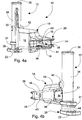
- the stripping blade according to the invention includes an attachment part 12, a blade part 14, and an attachment point 44.
- the attachment part 12 is preferably a sleeve-like structure 34, with the aid of which the stripping blade 10 is attached around an attachment shaft 114 (in Figure 2 ).
- an attachment support surface 30 In the upper part of the attachment part 12 there can be a thickening, i.e. an attachment support surface 30, with the aid of which the stripping blade 10 is supported on the harvester.
- the attachment support surface 30 preferably has a diameter greater than that of the sleeve-like structure 34, thus giving a greater axial surface in the attachment support surface 30 for mounting bearings.
- the sleeve-like structure 34 too can thus be made as thin as its durability permits.
- An at least partly curved blade part 14, with the aid of which the stripping of the branches of the tree takes place, is, for its part, attached to the attachment part 12.
- the blade part 14 includes a blade surface 16 that essentially conforms at least partly to the tree's trunk and a support structure 26 that conforms to the shape of the blade surface 16 and is attached at right angles to the blade surface 16.
- the support structure 26 is located on the opposite side of the blade surface 16 of the stripping blade 10 relative to the tree.
- the attachment point 44 is located on the base 28, which is located on the opposite side of the attachment part 12 relative to the blade part 14. With the aid of the attachment point 44, the operating device driving the stripping blade 10 can be attached to the stripping blade 10 in order to move it.
- the blade surface 16 is given a curved shape to conform to the shape of the tree.
- the blade part 14 also includes a butt 20, which joins the blade surface to the attachment part 12.
- the support structure 26 is preferably continuous over the entire length of the blade part, or at least over more than 15% of it.
- the support structure 26 is formed of two support surfaces 18.
- the stripping blade according to the invention is preferably cast to form a single individual piece. This permits the stripping blade to be made entirely or at least mostly without welding seams, thus improving the blade's structure.
- the hollow space can also consist of several separate portions, in which case the hollow space will not be unified and continuous over the entire length of the stripping blade.
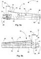
- Figure 4a shows a stripping blade 10 according to a first embodiment seen from the end of the blade part 14 towards the attachment part 12.
- the support structure 26 is formed of two essentially parallel support surfaces 18, which are attached to each other with the aid of an outer surface 38 and an inner surface 36.
- An empty space remains between these aforementioned parts, i.e. the stripping blade 10 is hollow.
- the hollow space 60 is surrounded by a mainly unified structure, which improves the torsional stiffness of the stripping blade.
- the hollow construction lightens the total weight of the stripping blade 10 and permits the transfer of various liquids/gases, for example for channels (not shown) used for feeding colour marking, and/or urea, for spreading timber preservative, or a stump treatment agent through the hollow space right to the point part of the stripping blade.
- the hollow space 60 can also be used to feed a hydraulic hose through.
- the strength of the hollow structure corresponds to that of a solid structure, as practically no forces act on the centre part of a solid support structure.
- the hollow space 60 is preferably open at both ends 61, so that colour-marking and/or urea-feed channels can be easily led into the support structure 26.
- the open ends act as openings for the support of the core in the casting mould.
- the butt 20 of the blade part 14 widens from the height of the blade surface 16 to nearly the height of the attachment part 12 as it nears the widening portion 46 of the attachment part 12.
- the attachment surface between the butt 20 and the attachment part 12 is as wide and sturdy as possible.
- the base 28 is attached to the lower surface of the attachment part 12.
- the base 28 is formed of two base parts 22 and 31, between which the operating device driving the stripping blade 10 is pivoted.
- the stripping blade also includes holes 40 for supporting the core in the casting stage and for lightening the stripping blade.
- the holes can be utilized, for example, for installing channels, i.e. for example hoses/pipes, in the hollow space 60.
- the mould In the casting stage of the stripping blade, the mould includes two halves, in the first of which is the mould and core and in the second the other half of the mould.
- the core is supported during casting with the aid of sand plugs through holes to the interior of the hollow pieces, the core made of sand being vibrated out from inside the hollow pieces once the cast stripping blade has hardened.
- the holes do not weaken the structure of the stripping blade as they are located at points at which large stresses do not naturally occur.
- the holes 40 can be made in the blade part 14 in the surface opposite to the surface coming against the tree.
- the actual blade surface can thus be unbroken and unified.
- the hollow space 60 of the support structure 26 is preferably continuous.
- the reference number 42 refers to a housing for a grease nipple.
- the holes can be made in the stripping blade from any direction at all, even parallel to the longitudinal axis of the stripping blade, as long as they extend into the hollow space.
- the blade surface 16 of the stripping blade 10 can be sharpened at both the upper and lower edges and the tree can be moved by the harvester in either direction relative to the stripping blades, in order to perform stripping.
- the cast structure is excellent, as the sharpening shape in the cast stripping blade comes nearly ready during casting.
- the sharpening of a cast blade requires considerably less work to finish than the machining of all the sharpening of a welded blade as in solutions according to the prior art.
- the dimensionally precise casting makes it unnecessary to machine the blade part coming against the tree.
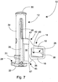
- Figure 7 shows a cross-section of the construction of the stripping blade.
- the figure shows how the blade surface 16 is advantageously sharpened above and below.
- the wall thickness of the stripping blade 10 is essentially the same in the outer surface 38 and in the support surfaces 18.
- the inner surface 36 is advantageously formed by the blade surface 16.
- the cross-section of the hollow space can have any shape whatever suitable to the purpose.
- FIGs 8a - 12 show a stripping blade 10 according to a second embodiment of the invention.
- the second stripping blade 10 too is formed of the same basic components as the first embodiment, i.e. an attachment part 12, a blade part 14, a support structure 26 for the blade part 14, and an attachment point 44.
- the technical difference between these two embodiments is in the support structure 26 of the blade part 14, which in the second embodiment too is hollow, but which is not intended for running colour-marking and/or urea-spreading hoses through it.
- the hollow space inside the support structure 26 is considerably smaller than in the first embodiment shown in Figures 3a - 7 .
- the holes 40 are preferably made in the blade surface 16, i.e. in the surface of the blade part 14 that comes against the tree.
- the holes can also be manufactured in any direction whatever, as long as they extend into the hollow space.
- the blade surface 16 can be formed to curve in two directions, i.e. the blade surface 16 is curved both according to the shape of the tree surface from the point to the butt 20 and in the height direction of the blade surface 16 from the bottom upwards.
- the blade surface 16 will then consist of an essentially parallel upper surface 52 and a lower surface 48, as well as of an intermediate surface 50 at an angle between them.
- the support structure 26 of the blade part 14 is considerably lower in height than the support structure of the first embodiment.
- the support structure 26 is not used to feed channels through, its only task is to stiffen the blade part 14.
- the support structure 26 can be relatively low, 10 - 35%, preferably 15 - 25% of the height of the blade surface 16.
- the support structure 26 is hollow, thus reducing the total weight of the stripping blade 10.
- the hollow space of the support structure 26 is open at at least one end, to support the core.
- the butt 20 of the blade part 14 can be lower than that in the stripping blade of the first embodiment.
- the cross-section of Figure 12 shows that in the second embodiment too the support structure 26 is formed of support surfaces 18, as well as the outer surface 38 and the inner surface 36 formed by the blade surface 16.
- both the upper and lower surfaces of the blade surface can be sharpened for stripping, so that the direction of stripping a tree is of no significance in terms of the final result.
- the stripping blade 10 when viewed from the upper edge 43 and/or the lower edge 45 of the blade part in a direction perpendicular to the longitudinal direction of the blade part 14, there can be a sharpening portion 47, shown in Figures 7 and 12 .
- the sharpening portion 47 is intended to facilitate manufacture, as sharp corners cannot be made by casting.
- a 2 - 10 mm thick, preferably 3 - 7 mm thick sharpening portion, in the area of which the blade surface 16 is sharpened to a sharp point, is cast into the blade part.
- the thicker portion is ground off, so that the sharpened stripping blade does not have a thicker portion.
- the sharpening portion is preferably continuous over the entire length of the blade part.
- the structure of the stripping blade according to the invention is lighter than the welded structures according to the prior art, which is reflected in the total weight of the forestry machine.
- work booms 103 are used, at the end of which the harvester 102 is suspended. If the harvester is being used to work, for example, at a distance of 10 - 11 m to the side of the forestry machine, an additional kilogram added to the harvester will affect the weight of the whole forestry machine many times over. The work boom must then be stronger and the chassis of the forestry machine will in turn have to carry larger loads. To make the forestry machine stable while working, the tracks must be widened and additional weights added to the tyres, so that the forestry machine will remaining standing.
- a heavier forestry machine will leave deeper ruts in soft ground.
- the weight of the harvester will increase by four kilograms. About 25 kg of additional weight will then be required in the centre of the forestry machine, if the harvester is 11 metres from the forestry machine and the forestry machine is tilted around the outer edge of a tyre 1.5 m from the centre point of the forestry machine.
- the cross-sectional surface area of the hollow space formed inside the support structure during casting is at least 100 mm 2 , preferably at least 200 mm 2 .
- the hollow space will then be large enough for the core used in casting to be able to be supported inside the support structure. Further, the hollow space will then be large enough for possible hoses for colour-marking or other accessories. For example, for colour marking, two hoses with a diameter of about 10 - 20 mm can be advantageously installed in the hollow space.
- the height of the support structure can be at least 25% of the height of the blade part, preferably at least 33% of the height of the blade part. It will then be possible to place a core inside the support structure for casting and it will be possible to place hoses or conductors inside the support structure.
- the blade part of the stripping blade In the longitudinal direction of the tree, the blade part of the stripping blade has a height typically 8 - 15 cm high and the support structure in turn 4 - 8 cm high.
- the distance between the support structure and the blade structure as the first component to meet a tree branch is at least 2 cm, so that the blade surface will cut the branch before the branch strikes the support structure of the blade part in the direction of travel.
- the material of the stripping blade according to the invention can be a metal or metal alloy suitable for the purpose, by which sufficient stiffness and durability can be achieved, but which nevertheless can be sharpened.
- a detachable extension piece can be attached to the end of the stripping blade.
- the hollow space of the support structure can also be used as a flow channel for liquid, through which the liquid flows towards the point part of the blade part.
- the support structure itself will act as the walls of the flow channel.
- the holes belonging to the blade part are plugged.
Landscapes
- Life Sciences & Earth Sciences (AREA)
- Biodiversity & Conservation Biology (AREA)
- Ecology (AREA)
- Forests & Forestry (AREA)
- Environmental Sciences (AREA)
- Knives (AREA)
- Harvester Elements (AREA)
Claims (12)
- Lame d'ébranchage pour un engin forestier, qui comprend une partie de fixation (12) pour monter la lame d'ébranchage (10) par pivot à l'engin forestier (100), et une partie lame (14) au moins partiellement courbe attachée à ladite partie de fixation (12) pour ébrancher un arbre, laquelle partie lame (14) comprend une surface de la lame (16) qui s'adapte au moins partiellement au tronc de l'arbre et une structure de soutien (26) correspondant à la surface de la lame (16) liée à la surface extérieure de la surface de la lame (16) par rapport à l'arbre, ladite lame d'ébranchage (10) est principalement une structure moulée, caractérisée en ce que ladite structure de soutien (26) est une structure moulée ayant un espace creux (60), qui est disposé de sorte à agir en tant que canal d'écoulement pour un liquide/gaz ou à contenir des tuyaux agissant en tant que canaux d'écoulement pour un liquide/gaz, pour transférer un liquide/gaz.
- Lame d'ébranchage selon la revendication 1, caractérisée en ce que la partie lame (14) comprend au moins un trou (40) s'étendant dans la zone centrale de l'espace creux (60) pour le soutien d'un noyau.
- Lame d'ébranchage selon l'une quelconque des revendications 1 ou 2, caractérisée en ce que le bord supérieur (43) et/ou le bord inférieur (45) de la partie lame (14) comprend une portion d'aiguisage (47) pour faciliter le moulage de la lame d'ébranchage (10), dans la zone de laquelle portion d'aiguisage (47) l'épaisseur de la surface de la lame (16) est de 2 à 10 mm, de préférence de 3 à 7 mm.
- Lame d'ébranchage selon la revendication 3, caractérisée en ce que ladite portion d'aiguisage (47) est continue sur toute la longueur de la surface de la lame (16) et est une zone mesurant de 2 à 10 mm, de préférence de 3 à 7 mm dans le sens d'ébranchage de l'arbre.
- Lame d'ébranchage selon l'une quelconque des revendications 1 à 4, caractérisée en ce que dans la partie lame (14) il y a une structure principalement ininterrompue entourant l'espace creux (60) pour améliorer la rigidité torsionnelle de la lame d'ébranchage (10).
- Lame d'ébranchage selon l'une quelconque des revendications 1 à 5, caractérisée en ce que l'espace creux (60) est disposé sur au moins 15 %, de préférence sur 30 à 60 % de la longueur de la partie lame (14).
- Lame d'ébranchage selon l'une quelconque des revendications 1 à 6, caractérisée en ce que la lame d'ébranchage est moulée pour former une seule pièce de métal ininterrompue.
- Lame d'ébranchage selon l'une quelconque des revendications 1 à 7, caractérisée en ce que la partie fixation (12) de la lame d'ébranchage (10) comprend une structure en forme de manchon (34) et une surface de soutien de fixation (30) à son extrémité pour soutenir la structure en forme de manchon (34) contre l'engin forestier, où le diamètre de ladite surface de soutien de fixation (30) est supérieur au diamètre de la structure en forme de manchon (34) .
- Lame d'ébranchage selon l'une quelconque des revendications 1 à 8, caractérisée en ce que la superficie en coupe transversale de l'espace creux (60) dans la partie lame (14) est d'au moins 100 mm2, de préférence d'au moins 200 mm2.
- Lame d'ébranchage selon l'une quelconque des revendications 1 à 9, caractérisée en ce que la hauteur de la structure de soutien (26) est d'au moins 25 % de la hauteur de la partie lame (14), de préférence de 33 % de la hauteur de la partie lame (14).
- Lame d'ébranchage selon l'une quelconque des revendications 1 à 10, caractérisée en ce que la structure de soutien (26) est attachée à la surface de la lame (16) de sorte qu'elle est à une distance d'au moins 1,5 cm, de préférence d'au moins 2 cm du bord supérieur (43) et du bord inférieur (45) de la partie lame (14).
- Lame d'ébranchage selon l'une quelconque des revendications 1 à 11, caractérisée en ce que la structure de soutien (26) est ouverte longitudinalement aux deux extrémités (61) de la structure de soutien (26).
Applications Claiming Priority (2)
| Application Number | Priority Date | Filing Date | Title |
|---|---|---|---|
| FI20125737 | 2012-06-28 | ||
| PCT/FI2013/050686 WO2014001629A1 (fr) | 2012-06-28 | 2013-06-20 | Lame arracheuse pour machine forestière |
Publications (3)
| Publication Number | Publication Date |
|---|---|
| EP2866552A1 EP2866552A1 (fr) | 2015-05-06 |
| EP2866552A4 EP2866552A4 (fr) | 2016-03-30 |
| EP2866552B1 true EP2866552B1 (fr) | 2020-03-04 |
Family
ID=49578026
Family Applications (1)
| Application Number | Title | Priority Date | Filing Date |
|---|---|---|---|
| EP13809097.2A Active EP2866552B1 (fr) | 2012-06-28 | 2013-06-20 | Lame arracheuse pour machine forestière |
Country Status (5)
| Country | Link |
|---|---|
| US (1) | US9854753B2 (fr) |
| EP (1) | EP2866552B1 (fr) |
| FI (1) | FI10261U1 (fr) |
| RU (1) | RU2617326C2 (fr) |
| WO (1) | WO2014001629A1 (fr) |
Families Citing this family (5)
| Publication number | Priority date | Publication date | Assignee | Title |
|---|---|---|---|---|
| AU2013203686B2 (en) * | 2013-02-28 | 2016-01-07 | Waratah Nz Limited | A system, device, and method for processing a length of material |
| FI125917B (fi) * | 2014-08-26 | 2016-04-15 | Ponsse Oyj | Sovitelma puomistossa |
| EP4005370B1 (fr) * | 2017-07-04 | 2025-01-22 | Andreas Stihl AG & Co. KG | Système d'appareil forestier |
| EP3809824B1 (fr) * | 2018-05-02 | 2023-06-21 | Engineering Services Rotorua Limited | Insert de couteau remplaçable pour tête d'ébranchage |
| SE547635C2 (en) * | 2021-11-19 | 2025-10-28 | Lauri Ketonen | A harvesting apparatus for felling, delimbing and sectioning trees comprising beveled rear delimbing knives |
Family Cites Families (6)
| Publication number | Priority date | Publication date | Assignee | Title |
|---|---|---|---|---|
| US3981336A (en) * | 1972-06-06 | 1976-09-21 | L & L Logging Research Limited | Tree harvester |
| US4387752A (en) * | 1981-08-27 | 1983-06-14 | Rockland Manufacturing Co., Inc. | Tree shearing apparatus |
| BE1013070A3 (fr) * | 1998-09-03 | 2001-09-04 | Charlier Alain | Machine pour prendre et ebrancher des troncs d'arbres. |
| US8002004B2 (en) * | 2009-06-12 | 2011-08-23 | Waratah Nz Limited | Delimb arm cam stop |
| FI20095887A0 (fi) | 2009-08-28 | 2009-08-28 | Lako Forest Oy Ltd | Hakkuupää ja menetelmä karsinta- tai kuorintaominaisuuksien ohjaamiseksi hakkuupäässä |
| NZ589628A (en) * | 2010-11-30 | 2012-06-29 | A W Trinder Ltd | A grappling and severing head for gripping and severing a tree stem |
-
2013
- 2013-06-20 US US14/411,167 patent/US9854753B2/en active Active
- 2013-06-20 RU RU2015102628A patent/RU2617326C2/ru active
- 2013-06-20 WO PCT/FI2013/050686 patent/WO2014001629A1/fr not_active Ceased
- 2013-06-20 EP EP13809097.2A patent/EP2866552B1/fr active Active
- 2013-06-27 FI FIU20134154U patent/FI10261U1/fi active IP Right Grant
Non-Patent Citations (1)
| Title |
|---|
| None * |
Also Published As
| Publication number | Publication date |
|---|---|
| WO2014001629A1 (fr) | 2014-01-03 |
| FI10261U1 (fi) | 2013-10-11 |
| EP2866552A4 (fr) | 2016-03-30 |
| EP2866552A1 (fr) | 2015-05-06 |
| RU2015102628A (ru) | 2016-08-20 |
| US9854753B2 (en) | 2018-01-02 |
| US20150195999A1 (en) | 2015-07-16 |
| RU2617326C2 (ru) | 2017-04-24 |
Similar Documents
| Publication | Publication Date | Title |
|---|---|---|
| EP2866552B1 (fr) | Lame arracheuse pour machine forestière | |
| EP2596699A1 (fr) | Appareil pour ébrancher les arbres | |
| SE533130C2 (sv) | Fordon för avverkning av skog och/eller transport av virkesbitar | |
| EP2387303B1 (fr) | Dispositif d'abattage avec lame d'ébranchage mobile | |
| FI70110C (fi) | Anordning vid faell- och gripaggregat | |
| JPH084432B2 (ja) | 木材伐採機のためのジブに取付けられた懸架装置 | |
| FI118890B (fi) | Työkonejärjestelmä, johon kuuluu välineet prosessoitavan puun kaatamiseksi | |
| EP2405738A2 (fr) | Tête d'abattage-ébranchage et son fonctionnement | |
| EP0474687B1 (fr) | Machine de degrossissage de bois d' uvre | |
| FI122419B (fi) | Kirves | |
| SE0002143D0 (sv) | Avkvistnings- och kapningshuvud för en skogsvavverkningsmaskin | |
| CA2746102C (fr) | Tete d'abattage-ebranchage | |
| CN112352572B (zh) | 一种履带式液压驱动立木整枝机 | |
| WO2011023857A1 (fr) | Tête d'abattage-ébranchage et procédé de contrôle des propriétés d'écorçage de la tête d'abattage-ébranchage | |
| FI127875B (fi) | Työkonekäyttöinen raivauslaite ja menetelmä metsänhoidolliseen raivaukseen ja maanmuokkaukseen | |
| EP2825022B1 (fr) | Système de chargement mobile pour engin d'abattage forestier | |
| AU2007209265A1 (en) | Debarking arrangement for a wood-handling device | |
| FI122801B (fi) | Energiapuukoura | |
| FI121564B (sv) | Stamkvistare | |
| FI119636B (fi) | Nosturirakenne ja lisävarren rakenne | |
| AU2007201892A1 (en) | Method and an apparatus for debarking a tree trunk and a debarking member | |
| FI130899B1 (fi) | Takaterät hakkuulaitteessa | |
| WO2014033364A1 (fr) | Dispositif pour le maniement d'arbres et procédé correspondant | |
| FI63653B (fi) | Mobil maskin foer behandling av traedstammar | |
| FI121158B (fi) | Harvesterin katkaisulaite |
Legal Events
| Date | Code | Title | Description |
|---|---|---|---|
| PUAI | Public reference made under article 153(3) epc to a published international application that has entered the european phase |
Free format text: ORIGINAL CODE: 0009012 |
|
| 17P | Request for examination filed |
Effective date: 20150126 |
|
| AK | Designated contracting states |
Kind code of ref document: A1 Designated state(s): AL AT BE BG CH CY CZ DE DK EE ES FI FR GB GR HR HU IE IS IT LI LT LU LV MC MK MT NL NO PL PT RO RS SE SI SK SM TR |
|
| AX | Request for extension of the european patent |
Extension state: BA ME |
|
| DAX | Request for extension of the european patent (deleted) | ||
| RA4 | Supplementary search report drawn up and despatched (corrected) |
Effective date: 20160225 |
|
| RIC1 | Information provided on ipc code assigned before grant |
Ipc: A01G 23/099 20060101ALI20160219BHEP Ipc: A01G 23/095 20060101AFI20160219BHEP |
|
| STAA | Information on the status of an ep patent application or granted ep patent |
Free format text: STATUS: EXAMINATION IS IN PROGRESS |
|
| 17Q | First examination report despatched |
Effective date: 20170202 |
|
| GRAP | Despatch of communication of intention to grant a patent |
Free format text: ORIGINAL CODE: EPIDOSNIGR1 |
|
| STAA | Information on the status of an ep patent application or granted ep patent |
Free format text: STATUS: GRANT OF PATENT IS INTENDED |
|
| RIC1 | Information provided on ipc code assigned before grant |
Ipc: A01G 23/095 20060101AFI20190905BHEP |
|
| INTG | Intention to grant announced |
Effective date: 20190927 |
|
| RIN1 | Information on inventor provided before grant (corrected) |
Inventor name: KOHIO, TONI Inventor name: KAATRASALO, TERO |
|
| GRAS | Grant fee paid |
Free format text: ORIGINAL CODE: EPIDOSNIGR3 |
|
| GRAA | (expected) grant |
Free format text: ORIGINAL CODE: 0009210 |
|
| STAA | Information on the status of an ep patent application or granted ep patent |
Free format text: STATUS: THE PATENT HAS BEEN GRANTED |
|
| RIN1 | Information on inventor provided before grant (corrected) |
Inventor name: KOHIO, TONI Inventor name: KAATRASALO, TERO |
|
| AK | Designated contracting states |
Kind code of ref document: B1 Designated state(s): AL AT BE BG CH CY CZ DE DK EE ES FI FR GB GR HR HU IE IS IT LI LT LU LV MC MK MT NL NO PL PT RO RS SE SI SK SM TR |
|
| REG | Reference to a national code |
Ref country code: GB Ref legal event code: FG4D |
|
| REG | Reference to a national code |
Ref country code: CH Ref legal event code: EP |
|
| REG | Reference to a national code |
Ref country code: AT Ref legal event code: REF Ref document number: 1239348 Country of ref document: AT Kind code of ref document: T Effective date: 20200315 |
|
| REG | Reference to a national code |
Ref country code: DE Ref legal event code: R096 Ref document number: 602013066509 Country of ref document: DE |
|
| REG | Reference to a national code |
Ref country code: IE Ref legal event code: FG4D |
|
| REG | Reference to a national code |
Ref country code: FI Ref legal event code: FGE |
|
| REG | Reference to a national code |
Ref country code: SE Ref legal event code: TRGR |
|
| PG25 | Lapsed in a contracting state [announced via postgrant information from national office to epo] |
Ref country code: NO Free format text: LAPSE BECAUSE OF FAILURE TO SUBMIT A TRANSLATION OF THE DESCRIPTION OR TO PAY THE FEE WITHIN THE PRESCRIBED TIME-LIMIT Effective date: 20200604 Ref country code: RS Free format text: LAPSE BECAUSE OF FAILURE TO SUBMIT A TRANSLATION OF THE DESCRIPTION OR TO PAY THE FEE WITHIN THE PRESCRIBED TIME-LIMIT Effective date: 20200304 |
|
| REG | Reference to a national code |
Ref country code: NL Ref legal event code: MP Effective date: 20200304 |
|
| PG25 | Lapsed in a contracting state [announced via postgrant information from national office to epo] |
Ref country code: GR Free format text: LAPSE BECAUSE OF FAILURE TO SUBMIT A TRANSLATION OF THE DESCRIPTION OR TO PAY THE FEE WITHIN THE PRESCRIBED TIME-LIMIT Effective date: 20200605 Ref country code: BG Free format text: LAPSE BECAUSE OF FAILURE TO SUBMIT A TRANSLATION OF THE DESCRIPTION OR TO PAY THE FEE WITHIN THE PRESCRIBED TIME-LIMIT Effective date: 20200604 Ref country code: HR Free format text: LAPSE BECAUSE OF FAILURE TO SUBMIT A TRANSLATION OF THE DESCRIPTION OR TO PAY THE FEE WITHIN THE PRESCRIBED TIME-LIMIT Effective date: 20200304 Ref country code: LV Free format text: LAPSE BECAUSE OF FAILURE TO SUBMIT A TRANSLATION OF THE DESCRIPTION OR TO PAY THE FEE WITHIN THE PRESCRIBED TIME-LIMIT Effective date: 20200304 |
|
| REG | Reference to a national code |
Ref country code: LT Ref legal event code: MG4D |
|
| PG25 | Lapsed in a contracting state [announced via postgrant information from national office to epo] |
Ref country code: NL Free format text: LAPSE BECAUSE OF FAILURE TO SUBMIT A TRANSLATION OF THE DESCRIPTION OR TO PAY THE FEE WITHIN THE PRESCRIBED TIME-LIMIT Effective date: 20200304 |
|
| PG25 | Lapsed in a contracting state [announced via postgrant information from national office to epo] |
Ref country code: ES Free format text: LAPSE BECAUSE OF FAILURE TO SUBMIT A TRANSLATION OF THE DESCRIPTION OR TO PAY THE FEE WITHIN THE PRESCRIBED TIME-LIMIT Effective date: 20200304 Ref country code: CZ Free format text: LAPSE BECAUSE OF FAILURE TO SUBMIT A TRANSLATION OF THE DESCRIPTION OR TO PAY THE FEE WITHIN THE PRESCRIBED TIME-LIMIT Effective date: 20200304 Ref country code: RO Free format text: LAPSE BECAUSE OF FAILURE TO SUBMIT A TRANSLATION OF THE DESCRIPTION OR TO PAY THE FEE WITHIN THE PRESCRIBED TIME-LIMIT Effective date: 20200304 Ref country code: PT Free format text: LAPSE BECAUSE OF FAILURE TO SUBMIT A TRANSLATION OF THE DESCRIPTION OR TO PAY THE FEE WITHIN THE PRESCRIBED TIME-LIMIT Effective date: 20200729 Ref country code: EE Free format text: LAPSE BECAUSE OF FAILURE TO SUBMIT A TRANSLATION OF THE DESCRIPTION OR TO PAY THE FEE WITHIN THE PRESCRIBED TIME-LIMIT Effective date: 20200304 Ref country code: SM Free format text: LAPSE BECAUSE OF FAILURE TO SUBMIT A TRANSLATION OF THE DESCRIPTION OR TO PAY THE FEE WITHIN THE PRESCRIBED TIME-LIMIT Effective date: 20200304 Ref country code: LT Free format text: LAPSE BECAUSE OF FAILURE TO SUBMIT A TRANSLATION OF THE DESCRIPTION OR TO PAY THE FEE WITHIN THE PRESCRIBED TIME-LIMIT Effective date: 20200304 Ref country code: IS Free format text: LAPSE BECAUSE OF FAILURE TO SUBMIT A TRANSLATION OF THE DESCRIPTION OR TO PAY THE FEE WITHIN THE PRESCRIBED TIME-LIMIT Effective date: 20200704 Ref country code: SK Free format text: LAPSE BECAUSE OF FAILURE TO SUBMIT A TRANSLATION OF THE DESCRIPTION OR TO PAY THE FEE WITHIN THE PRESCRIBED TIME-LIMIT Effective date: 20200304 |
|
| REG | Reference to a national code |
Ref country code: AT Ref legal event code: MK05 Ref document number: 1239348 Country of ref document: AT Kind code of ref document: T Effective date: 20200304 |
|
| REG | Reference to a national code |
Ref country code: DE Ref legal event code: R097 Ref document number: 602013066509 Country of ref document: DE |
|
| PLBE | No opposition filed within time limit |
Free format text: ORIGINAL CODE: 0009261 |
|
| STAA | Information on the status of an ep patent application or granted ep patent |
Free format text: STATUS: NO OPPOSITION FILED WITHIN TIME LIMIT |
|
| PG25 | Lapsed in a contracting state [announced via postgrant information from national office to epo] |
Ref country code: DK Free format text: LAPSE BECAUSE OF FAILURE TO SUBMIT A TRANSLATION OF THE DESCRIPTION OR TO PAY THE FEE WITHIN THE PRESCRIBED TIME-LIMIT Effective date: 20200304 Ref country code: IT Free format text: LAPSE BECAUSE OF FAILURE TO SUBMIT A TRANSLATION OF THE DESCRIPTION OR TO PAY THE FEE WITHIN THE PRESCRIBED TIME-LIMIT Effective date: 20200304 Ref country code: AT Free format text: LAPSE BECAUSE OF FAILURE TO SUBMIT A TRANSLATION OF THE DESCRIPTION OR TO PAY THE FEE WITHIN THE PRESCRIBED TIME-LIMIT Effective date: 20200304 Ref country code: MC Free format text: LAPSE BECAUSE OF FAILURE TO SUBMIT A TRANSLATION OF THE DESCRIPTION OR TO PAY THE FEE WITHIN THE PRESCRIBED TIME-LIMIT Effective date: 20200304 |
|
| REG | Reference to a national code |
Ref country code: CH Ref legal event code: PL |
|
| 26N | No opposition filed |
Effective date: 20201207 |
|
| PG25 | Lapsed in a contracting state [announced via postgrant information from national office to epo] |
Ref country code: PL Free format text: LAPSE BECAUSE OF FAILURE TO SUBMIT A TRANSLATION OF THE DESCRIPTION OR TO PAY THE FEE WITHIN THE PRESCRIBED TIME-LIMIT Effective date: 20200304 Ref country code: SI Free format text: LAPSE BECAUSE OF FAILURE TO SUBMIT A TRANSLATION OF THE DESCRIPTION OR TO PAY THE FEE WITHIN THE PRESCRIBED TIME-LIMIT Effective date: 20200304 |
|
| GBPC | Gb: european patent ceased through non-payment of renewal fee |
Effective date: 20200620 |
|
| PG25 | Lapsed in a contracting state [announced via postgrant information from national office to epo] |
Ref country code: LU Free format text: LAPSE BECAUSE OF NON-PAYMENT OF DUE FEES Effective date: 20200620 |
|
| REG | Reference to a national code |
Ref country code: BE Ref legal event code: MM Effective date: 20200630 |
|
| PG25 | Lapsed in a contracting state [announced via postgrant information from national office to epo] |
Ref country code: CH Free format text: LAPSE BECAUSE OF NON-PAYMENT OF DUE FEES Effective date: 20200630 Ref country code: GB Free format text: LAPSE BECAUSE OF NON-PAYMENT OF DUE FEES Effective date: 20200620 Ref country code: IE Free format text: LAPSE BECAUSE OF NON-PAYMENT OF DUE FEES Effective date: 20200620 Ref country code: LI Free format text: LAPSE BECAUSE OF NON-PAYMENT OF DUE FEES Effective date: 20200630 Ref country code: FR Free format text: LAPSE BECAUSE OF NON-PAYMENT OF DUE FEES Effective date: 20200630 |
|
| PG25 | Lapsed in a contracting state [announced via postgrant information from national office to epo] |
Ref country code: BE Free format text: LAPSE BECAUSE OF NON-PAYMENT OF DUE FEES Effective date: 20200630 |
|
| PG25 | Lapsed in a contracting state [announced via postgrant information from national office to epo] |
Ref country code: TR Free format text: LAPSE BECAUSE OF FAILURE TO SUBMIT A TRANSLATION OF THE DESCRIPTION OR TO PAY THE FEE WITHIN THE PRESCRIBED TIME-LIMIT Effective date: 20200304 Ref country code: MT Free format text: LAPSE BECAUSE OF FAILURE TO SUBMIT A TRANSLATION OF THE DESCRIPTION OR TO PAY THE FEE WITHIN THE PRESCRIBED TIME-LIMIT Effective date: 20200304 Ref country code: CY Free format text: LAPSE BECAUSE OF FAILURE TO SUBMIT A TRANSLATION OF THE DESCRIPTION OR TO PAY THE FEE WITHIN THE PRESCRIBED TIME-LIMIT Effective date: 20200304 |
|
| PG25 | Lapsed in a contracting state [announced via postgrant information from national office to epo] |
Ref country code: MK Free format text: LAPSE BECAUSE OF FAILURE TO SUBMIT A TRANSLATION OF THE DESCRIPTION OR TO PAY THE FEE WITHIN THE PRESCRIBED TIME-LIMIT Effective date: 20200304 Ref country code: AL Free format text: LAPSE BECAUSE OF FAILURE TO SUBMIT A TRANSLATION OF THE DESCRIPTION OR TO PAY THE FEE WITHIN THE PRESCRIBED TIME-LIMIT Effective date: 20200304 |
|
| PGFP | Annual fee paid to national office [announced via postgrant information from national office to epo] |
Ref country code: FI Payment date: 20250617 Year of fee payment: 13 |
|
| PGFP | Annual fee paid to national office [announced via postgrant information from national office to epo] |
Ref country code: DE Payment date: 20250618 Year of fee payment: 13 |
|
| PGFP | Annual fee paid to national office [announced via postgrant information from national office to epo] |
Ref country code: SE Payment date: 20250618 Year of fee payment: 13 |