EP2865998A1 - Mesure matérialisée pour capteurs incrémentiels et son procédé de fabrication - Google Patents
Mesure matérialisée pour capteurs incrémentiels et son procédé de fabrication Download PDFInfo
- Publication number
- EP2865998A1 EP2865998A1 EP20130405121 EP13405121A EP2865998A1 EP 2865998 A1 EP2865998 A1 EP 2865998A1 EP 20130405121 EP20130405121 EP 20130405121 EP 13405121 A EP13405121 A EP 13405121A EP 2865998 A1 EP2865998 A1 EP 2865998A1
- Authority
- EP
- European Patent Office
- Prior art keywords
- line
- scattering
- regions
- width
- recesses
- Prior art date
- Legal status (The legal status is an assumption and is not a legal conclusion. Google has not performed a legal analysis and makes no representation as to the accuracy of the status listed.)
- Withdrawn
Links
- 239000000463 material Substances 0.000 title claims abstract description 30
- 238000000034 method Methods 0.000 title claims description 27
- 238000004519 manufacturing process Methods 0.000 title description 2
- 239000002184 metal Substances 0.000 claims description 35
- 238000009826 distribution Methods 0.000 claims description 18
- 238000003384 imaging method Methods 0.000 claims description 6
- 230000000873 masking effect Effects 0.000 claims description 5
- 238000001514 detection method Methods 0.000 claims description 2
- 238000012634 optical imaging Methods 0.000 claims description 2
- 210000001872 metatarsal bone Anatomy 0.000 claims 1
- 230000005855 radiation Effects 0.000 abstract description 16
- 238000005286 illumination Methods 0.000 description 14
- 238000005259 measurement Methods 0.000 description 8
- 230000003287 optical effect Effects 0.000 description 7
- 230000008859 change Effects 0.000 description 5
- 238000006073 displacement reaction Methods 0.000 description 4
- 230000008569 process Effects 0.000 description 4
- 230000009467 reduction Effects 0.000 description 4
- 238000011161 development Methods 0.000 description 3
- 230000018109 developmental process Effects 0.000 description 3
- 230000000737 periodic effect Effects 0.000 description 3
- 230000001419 dependent effect Effects 0.000 description 2
- 238000013461 design Methods 0.000 description 2
- 230000000694 effects Effects 0.000 description 2
- 238000003892 spreading Methods 0.000 description 2
- 230000007480 spreading Effects 0.000 description 2
- 230000002411 adverse Effects 0.000 description 1
- 230000008901 benefit Effects 0.000 description 1
- 230000015572 biosynthetic process Effects 0.000 description 1
- 238000000339 bright-field microscopy Methods 0.000 description 1
- 238000006243 chemical reaction Methods 0.000 description 1
- 238000001446 dark-field microscopy Methods 0.000 description 1
- 238000010586 diagram Methods 0.000 description 1
- 238000004049 embossing Methods 0.000 description 1
- 238000005530 etching Methods 0.000 description 1
- 230000008020 evaporation Effects 0.000 description 1
- 238000001704 evaporation Methods 0.000 description 1
- 238000002474 experimental method Methods 0.000 description 1
- 238000009472 formulation Methods 0.000 description 1
- 238000007373 indentation Methods 0.000 description 1
- 230000003993 interaction Effects 0.000 description 1
- 239000000203 mixture Substances 0.000 description 1
- 238000007711 solidification Methods 0.000 description 1
- 239000000758 substrate Substances 0.000 description 1
- 238000012360 testing method Methods 0.000 description 1
- 238000012549 training Methods 0.000 description 1
- LSGOVYNHVSXFFJ-UHFFFAOYSA-N vanadate(3-) Chemical compound [O-][V]([O-])([O-])=O LSGOVYNHVSXFFJ-UHFFFAOYSA-N 0.000 description 1
Images


Classifications
-
- G—PHYSICS
- G01—MEASURING; TESTING
- G01D—MEASURING NOT SPECIALLY ADAPTED FOR A SPECIFIC VARIABLE; ARRANGEMENTS FOR MEASURING TWO OR MORE VARIABLES NOT COVERED IN A SINGLE OTHER SUBCLASS; TARIFF METERING APPARATUS; MEASURING OR TESTING NOT OTHERWISE PROVIDED FOR
- G01D5/00—Mechanical means for transferring the output of a sensing member; Means for converting the output of a sensing member to another variable where the form or nature of the sensing member does not constrain the means for converting; Transducers not specially adapted for a specific variable
- G01D5/12—Mechanical means for transferring the output of a sensing member; Means for converting the output of a sensing member to another variable where the form or nature of the sensing member does not constrain the means for converting; Transducers not specially adapted for a specific variable using electric or magnetic means
- G01D5/244—Mechanical means for transferring the output of a sensing member; Means for converting the output of a sensing member to another variable where the form or nature of the sensing member does not constrain the means for converting; Transducers not specially adapted for a specific variable using electric or magnetic means influencing characteristics of pulses or pulse trains; generating pulses or pulse trains
- G01D5/245—Mechanical means for transferring the output of a sensing member; Means for converting the output of a sensing member to another variable where the form or nature of the sensing member does not constrain the means for converting; Transducers not specially adapted for a specific variable using electric or magnetic means influencing characteristics of pulses or pulse trains; generating pulses or pulse trains using a variable number of pulses in a train
- G01D5/2451—Incremental encoders
-
- G—PHYSICS
- G01—MEASURING; TESTING
- G01D—MEASURING NOT SPECIALLY ADAPTED FOR A SPECIFIC VARIABLE; ARRANGEMENTS FOR MEASURING TWO OR MORE VARIABLES NOT COVERED IN A SINGLE OTHER SUBCLASS; TARIFF METERING APPARATUS; MEASURING OR TESTING NOT OTHERWISE PROVIDED FOR
- G01D5/00—Mechanical means for transferring the output of a sensing member; Means for converting the output of a sensing member to another variable where the form or nature of the sensing member does not constrain the means for converting; Transducers not specially adapted for a specific variable
- G01D5/12—Mechanical means for transferring the output of a sensing member; Means for converting the output of a sensing member to another variable where the form or nature of the sensing member does not constrain the means for converting; Transducers not specially adapted for a specific variable using electric or magnetic means
- G01D5/244—Mechanical means for transferring the output of a sensing member; Means for converting the output of a sensing member to another variable where the form or nature of the sensing member does not constrain the means for converting; Transducers not specially adapted for a specific variable using electric or magnetic means influencing characteristics of pulses or pulse trains; generating pulses or pulse trains
- G01D5/245—Mechanical means for transferring the output of a sensing member; Means for converting the output of a sensing member to another variable where the form or nature of the sensing member does not constrain the means for converting; Transducers not specially adapted for a specific variable using electric or magnetic means influencing characteristics of pulses or pulse trains; generating pulses or pulse trains using a variable number of pulses in a train
- G01D5/2454—Encoders incorporating incremental and absolute signals
-
- G—PHYSICS
- G01—MEASURING; TESTING
- G01D—MEASURING NOT SPECIALLY ADAPTED FOR A SPECIFIC VARIABLE; ARRANGEMENTS FOR MEASURING TWO OR MORE VARIABLES NOT COVERED IN A SINGLE OTHER SUBCLASS; TARIFF METERING APPARATUS; MEASURING OR TESTING NOT OTHERWISE PROVIDED FOR
- G01D5/00—Mechanical means for transferring the output of a sensing member; Means for converting the output of a sensing member to another variable where the form or nature of the sensing member does not constrain the means for converting; Transducers not specially adapted for a specific variable
- G01D5/26—Mechanical means for transferring the output of a sensing member; Means for converting the output of a sensing member to another variable where the form or nature of the sensing member does not constrain the means for converting; Transducers not specially adapted for a specific variable characterised by optical transfer means, i.e. using infrared, visible, or ultraviolet light
- G01D5/32—Mechanical means for transferring the output of a sensing member; Means for converting the output of a sensing member to another variable where the form or nature of the sensing member does not constrain the means for converting; Transducers not specially adapted for a specific variable characterised by optical transfer means, i.e. using infrared, visible, or ultraviolet light with attenuation or whole or partial obturation of beams of light
- G01D5/34—Mechanical means for transferring the output of a sensing member; Means for converting the output of a sensing member to another variable where the form or nature of the sensing member does not constrain the means for converting; Transducers not specially adapted for a specific variable characterised by optical transfer means, i.e. using infrared, visible, or ultraviolet light with attenuation or whole or partial obturation of beams of light the beams of light being detected by photocells
- G01D5/347—Mechanical means for transferring the output of a sensing member; Means for converting the output of a sensing member to another variable where the form or nature of the sensing member does not constrain the means for converting; Transducers not specially adapted for a specific variable characterised by optical transfer means, i.e. using infrared, visible, or ultraviolet light with attenuation or whole or partial obturation of beams of light the beams of light being detected by photocells using displacement encoding scales
- G01D5/34707—Scales; Discs, e.g. fixation, fabrication, compensation
Definitions
- the present invention relates to a scale for incremental encoder according to the preamble of independent claim 1.
- the invention relates to a method for applying such a scale on a metal surface.
- the invention particularly relates to a dimensional scale having at least one incremental track with scattering areas and mirror areas arranged alternately in the longitudinal direction.
- the scattering regions of the at least one incremental track each have a multiplicity of essentially round recesses which are designed to diffuse light in an incident light.
- the mirror areas of the at least one incremental track have a substantially smooth surface, which is designed to reflect incident light reflecting.
- the material measure also has a pitch (P), which results from adding the width of one of the scattering regions (23) and the width of one of the mirror regions (24).
- P pitch
- the scale is periodic, with the period length of the scale being defined as a pitch.
- the pitch is generally defined by the geometry of the sensor device which is to be used to run the dimensional scale.
- the pitch for a given sensor is a constant of the dimensional scale. Only the width of the scattering and mirror areas can therefore be varied to a certain extent.
- Such dimensional standards are known in principle from the prior art. These are especially found with incremental encoders Application. These are sensors for detecting changes in position (linear) or angle changes (rotating), which can detect a distance and path direction or angle change and direction of rotation.
- the known dimensional embodiments of incremental encoders have periodically repeating scattering areas, which are counted by a sensor device in order to detect the change in position.
- a dimensional scale of metal known which has scattering areas of a plurality of bar elements.
- the bar elements are parallel, narrow and not very deep, with their width and depth being dimensioned such that they can experience displacement in visible light only by their diffraction pattern, or can only be recognized by the diffraction pattern.
- they consist of the DE 2515574 known scattering areas of a plurality of line-like depressions (bar elements) with a width of the order of a micrometer and a depth, which is in the order of magnitude of a wavelength of the sensor light, with which the known material measure is illuminated in incident light.
- the dimensional embodiment comprises structured regions, which are structured with diffractive phase grating structures in the form of line gratings, and unstructured regions, which are each formed by a smooth (reflecting) surface.
- the angle of incidence of light incident on the surface is in this case, it is preferably selected such that light is diffracted at the diffractive phase grating structures in structured regions in such a way that a diffraction order of the diffracted light leaves the material measure vertically.
- the light incident on the unstructured areas is reflected at each surface, so that it leaves the unstructured areas (hereinafter also called “mirror areas”) at an angle of departure from the surface normal which is equal to the angle of incidence.
- the light diffracted substantially perpendicular to the surface at the structured regions is then imaged onto the photosensors of a sensor device, wherein the sensor device is preferably arranged such that the light reflected at the unstructured regions (mirror regions) is not detected by the photosensors of the sensor device. Accordingly, the structured regions as bright fields and the unstructured regions (mirror regions) can be detected as dark fields by means of the sensor device. If the sensor device is displaced along the incremental track, the sensor device detects above all the light diffracted at the structured areas (dark field measurement of the structured areas).
- the structured areas and the unstructured areas (mirror areas) are each arranged alternately one behind the other in a row and together form an incremental track.
- the structured areas are arranged at constant intervals and are separated by the mirror areas. Accordingly, a so-called mark is formed by each of the structured regions, wherein the respective marks of the incremental track can be counted by the sensor device and converted into a periodically changing sensor signal if the sensor device is moved relative to the marks in the longitudinal direction of the incremental track.
- the periodic sensor signal can be used by a computer unit to calculate the displacement along the scale.
- the sensor signal periodically changes during a movement of the sensor device in the longitudinal direction of the incremental track, it is possible to measure the respective sensor signal at different positions of the sensor device during a movement of the sensor device in the longitudinal direction of the incremental track and thus assign different measurement values for the sensor signal to different positions of the sensor device , Finally, interpolation between different measured values for the sensor signals makes it possible to determine an arbitrary position of the sensor device with high accuracy.
- the dimensional examples described above can be used for the highly accurate linear movement of, for example, workpieces and / or tools, for example in machine tools or in any handling systems.
- Scattering regions are often introduced into a highly reflective surface of a markable layer, for example a highly reflective metal surface, to produce the material measure.
- the highly reflective metal surface is partially roughened by high-energy radiation, such as laser radiation, in order to provide scattering areas within the metal surface.
- high-energy radiation such as laser radiation
- a marking carrier consisting of a substrate and a markable layer, wherein a highly reflective surface of the markable layer is partially roughened by means of high-energy radiation in order to produce the material measure.
- the marking-capable surface is melted by short laser pulses of a duration of about 20 nanoseconds, after which it comes in the pulse pauses for immediate re-solidification of the surface.
- the dimensional standards known from the prior art have the disadvantage that the sensor signal detected by the sensor device frequently has only a low contrast. This in turn can lead to individual scattering areas not being sufficiently recognized and insufficient detection of the displacement of the sensor relative to the dimensional scale. Furthermore, it is regarded as problematic in the case of the material embodiments known from the prior art that the sensor signals, which are obtainable by reflection on the material measure, have too low interpolability.
- the present invention has for its object to provide a material measure, with which the contrast of the sensor signal can be optimized in a simple manner. Furthermore, as far as possible interpolatable sensor signals should be able to be generated by the material measure.
- the scattering regions in the longitudinal direction of the at least one incremental track, be a Have width that is smaller than half the pitch.
- the width of the scattering regions is limited by the at least two line-like depressions.
- the dimensional standard according to the invention has the advantage that, by reducing the width of the scattering regions, compared with the width of the mirror regions, the contrast can be significantly increased. In particular, it is achieved by the reduction in the width of the scattering regions that the diffusely reflected light is mainly imaged onto the photosensors of the sensor device provided for this purpose. By contrast, neighboring sensor fields are only slightly affected in the case of small scatter zones, whereby the contrast of the sensor signal is significantly increased
- the at least two line-like recesses of the scattering areas are each formed of a plurality of substantially round recesses which are arranged overlapping each other.
- the scattering regions consist of a multiplicity of essentially round depressions, which overlap each other and form together line-like depressions.
- substantially round depressions is intended to express that the round depressions of the dimensional scale naturally do not have a perfectly round shape. This is due in particular to the fact that the depressions, as explained in detail later with reference to the method, are generated by laser pulses. Of course, therefore, the shape of the recesses is highly dependent on the properties of the metal surface, of the laser as well as the ambient conditions during the introduction of the depressions. Thus, elliptical and slightly angular depressions are also covered by this formulation. It follows, however, that the line-like recesses, which are generated by the overlapping arranged, round recesses can not always be aligned perfectly perpendicular to the longitudinal direction of the incremental track. Thus, the expression “essentially vertical line-like depressions” is to be understood as meaning that, due to different initial conditions, slight deviations in the production of the vertical depressions lie in the tolerance range of the dimensional scale according to the invention.
- the diffuse reflection of the incident light is essentially limited to the longitudinal direction of the incremental trace. Accordingly, the dimensional standard makes it possible to generate particularly reliable sensor signals and to effectively prevent crosstalk of the optical signals into adjacent sensor areas.
- the substantially circular recesses overlap at least 75%. Specifically, this means that each of the round wells has at least 75% of your surface area in common with the next well. It is thus formed between two adjacent wells a cut surface which corresponds to at least 75% of the surface area of the individual wells.
- the line-like depressions of the dimensional scale according to the invention need not, of course, consist of the essentially circular recesses just mentioned; rather, they may also be formed as continuous grooves. The only thing that matters is that the line-like Depressions form scattering areas which have a width which is not greater than half the pitch.
- the width of the scattering regions should not fall below a minimum in order to obtain a sufficient light output even with the reduced scattering regions. Accordingly, it is provided according to a further aspect of the inventive dimensional embodiment that the width of the scattering ranges is greater than 10% of the width of the pitch. In other words, it has been found that the spreading area preferably has a width which is between 10% and 50% of the width of the pitch. Particularly good results are achieved in particular if the scattering regions have a width which corresponds to 30% to 45% of the pitch, preferably 35% to 40% of the pitch, and in particular about 38% of the pitch.
- the period length is usually defined as a pitch. Accordingly, this results, as already mentioned above, in the dimensional embodiment according to the invention from an addition of the width of the scattering region and the width of the mirror region. According to a further embodiment, it is provided that the distance between two adjacent parallel, line-like depressions is greater than zero, that is, the line-like depressions do not adjoin one another. Moreover, the pitch of the line-like pits is accordingly smaller than half the pitch minus twice a width of the line-like pits, in the longitudinal direction of the incremental track. By adhering to these distances between the adjacent parallel line-like depressions, the contrast achievable by the dimensional embodiment is increased even further.
- the scattering areas each have at least three parallel, linear depressions which are aligned perpendicular to the longitudinal direction of the incremental track.
- the three parallel, linear depressions are arranged in particular at a distance of 6 microns to 9 microns, preferably 7.5 microns.
- a homogeneous intensity distribution of the diffusely reflected light along the scattering regions can also be produced by the scattering regions each having at least one shortened line-like depression having a first length which is shorter than a second length of at least one further line-like depression.
- the line-like depressions from which the scattering regions are respectively formed have different lengths perpendicular to the longitudinal direction of the incremental track.
- the shortened, line-shaped depression is located in the middle of the scattering area, while the lying on the outside line-like depressions have the second, unreduced length.
- the above-mentioned, at least one shortened, line-like depression can have, for example, a beginning and end region which is shorter than the at least one further line-like depression. Accordingly, the at least one shortened, linear depression is still always centered along the longitudinal axis of the first incremental track, but has a shortened length compared to the remaining line-like depressions. Alternatively or additionally, it is also conceivable that the at least one shortened, line-like depression opposite the at least one further line-like depression has a preferably central clearance, which forms an interruption between an initial and end region of the shortened line-like depression. In other words, the shortened, line-like depression according to this aspect is divided into two and has a central clearance. The shortened, line-like depression is therefore located only at the upper and lower end of the first incremental track.
- the material measure according to the invention further comprises a reference track, which is arranged parallel to the first incremental track.
- the reference track is in particular designed to indicate an absolute position of a measuring head along the dimensional scale.
- the reference track may have in the longitudinal direction alternately arranged reference scattering areas and mirror areas. Similar to what has already been mentioned in connection with the first incremental track, the reference scattering areas of the reference track can each have a multiplicity of line-like depressions which are designed to diffuse light in an incident manner.
- the mirror areas of the reference track can also have a substantially smooth surface.
- the incremental encoder In order to determine the respective absolute position of the measuring head at an arbitrary location, it is possible, for example, to measure a change in the relative position (measured via the first incremental track) of the measuring head relative to a specific reference mark (reference scattering area) of the reference track. Thus, it is possible by the reference track that the incremental encoder not only its position change, but also recorded the absolute position.
- the dimensional standard according to the invention is in particular designed to be used in conjunction with an optical incremental encoder.
- an optical incremental encoder has at least one dimensional standard according to the invention and a sensor device, which is designed to optically scan at least one incremental track of the material measure.
- the at least one sensor device of the incremental encoder can have a measuring head which can be moved relative to the material measure and has an optical imaging device for generating an image of the incremental track as well as a plurality of photosensors for capturing the image.
- the sensor device may, above all, be designed such that the photosensors generate a sinusoidal output signal when the image is acquired.
- the imaging device of the sensor device can have, for example, an elliptical scanning diaphragm.
- the photosensors of the sensor device for generating a sinusoidal output signal describe a substantially elliptical sensor surface. Due to the interaction of the inventive material measure with the above-mentioned sensor device, a particularly advantageous ratio between contrast and interpolability of the sensor signals is achieved, which will be explained in more detail later with reference to the figures.
- the following invention also relates to a method for applying the inventive dimensional scale to a metal surface.
- the inventive method has a step of providing a pulsed laser for generating a laser beam on.
- the metal surface is so exposed to laser radiation, so that a scattering area of at least two line-like recesses is formed, which has a width which is smaller than half the pitch of the scale.
- the exposure of the metal surface to the laser radiation takes place in particular for the duration of a first laser pulse.
- the laser beam is designed such that a first substantially round depression is formed on the metal surface.
- the laser beam is moved perpendicular to the longitudinal direction of the at least one incremental track.
- the method of the laser beam is carried out in particular continuously during the application of the metal surface.
- a further laser pulse By means of a further laser pulse, a further substantially round depression is produced at a further displacement position offset perpendicular to the incremental track.
- This process which is also known as laser scanning, can be carried out, for example, by means of a movable mirror, the mirror being operated vertically until a substantially line-like depression has been produced.
- a second, line-like depression is then produced, so that a scattering region is created which has a width that is less than or equal to half the pitch.
- a line-like depression with a length of about 1 mm can be provided for example about 600 pulses.
- the laser beam is moved by a method of the mirror and / or the metal surface between the individual pulses each perpendicular to the longitudinal direction of the at least one incremental track, so that the substantially round recesses overlap such that the at least two line-like depressions arise, which in Substantially perpendicular to the longitudinal direction of the incremental track are aligned.
- the laser beam may have a substantially circular beam having a diameter that is chosen such that the substantially circular pits have a diameter of 3.5 ⁇ m to 12 ⁇ m, preferably 6 ⁇ m to 9 ⁇ m and in particular about 7 ⁇ m.
- the laser can be operated with a power that is sufficient to form the substantially round recesses with a depth of about 0.5 microns.
- the centers of the substantially round recesses may be arranged at a distance of 0.1 ⁇ m to 10 ⁇ m in order to ensure that two of the essentially round recesses overlap each other, if these are arranged directly behind one another perpendicular to the longitudinal direction of the incremental track are arranged adjacent.
- the line-like recesses have particularly advantageous reflection properties when the laser beam is moved in such a way that an overlap of the substantially round recesses of at least 75% is formed.
- the laser beam is guided over a masking element which has at least two line-like openings before the metal surface is acted upon. Accordingly, an image of the line-like openings is imaged by the laser beam onto the metal surface in such a way that at least one scattering area results from at least two line-like depressions. In other words, the line-like depressions of a scattering region can be generated in accordance with this reaction in particular simultaneously.
- the laser beam is thereby as long as through the masking element on the metal surface directed until the at least two line-like recesses of the scattering range have a depth of about 0.5 microns and a width of 6 microns to 9 microns, in particular about 7 microns.
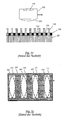
- the material measure 130 has a plurality of preferably elongated, transparent regions 131, which are arranged parallel to one another and separated from each other by non-transparent regions 132.
- the transmitted-light graduation 130 is irradiated from below in such a way that first light beams 110 pass through the transparent areas 131 of the graduated mass 130, while second light beams 120 are shielded from the non-transparent areas 132 of the graduated mass 130.
- the results in Fig. 1c illustrated, rectangular intensity distribution 200 of the light at the sensor 102 of the sensor device 101.
- the light beams 110 are imaged by the imaging device 104 of the sensor device 101 on the sensor surface 102, whereby on the sensor surface 102, the in Fig. 1b illustrated illumination pattern arises.
- Fig. 1b shows by way of example the illumination pattern which is formed by rectangular, transparent regions 131 on the sensor surface 102. In particular, this results in rectangular illumination regions 111, at which the first radiation 110 strikes the sensor surface 102.
- the sensor surface 102 has a plurality of substantially elliptical photosensors 103, which are guided past the illumination regions 111 by moving the sensor along the graduation 130.
- the elliptical photosensors 103 (for example, in the direction of the in Fig. 1b shown arrows) relative to the illumination areas 111 shifted.
- FIG. 1c shows a convolution of the rectangular light signal 200 with the elliptical photosensors 103, whereby the sinusoidal sensor signal 201 is formed.
- Fig. 1c the sensor signal 201 as a function of the position of the sensor device 101 during a movement of the sensor device 101 in the longitudinal direction of the graduated mass 130, ie in the direction Fig. 1b shown arrows, wherein in the horizontal direction, the position of the sensor device 101 and in the vertical direction, the sensor signal 201 is applied.
- the representation according to Fig. 1d can be taken from a known from the prior art reflected-light graduation 1 in a schematic plan view.
- the conventional dimensional examples 1 have at least one first incremental track 2 with scattering regions 3 and mirror regions 4 arranged alternately in the longitudinal direction X.
- the scattering regions 3 consist of a multiplicity of line-like depressions 5 arranged directly next to each other, which are designed to diffusely reflect incident light.
- the surface of the scattering regions 3 is roughened by the line-like depressions 5, as a result of which it has no specular, but diffuse, reflection properties.
- the mirror areas 4 are smooth (metal) surfaces which are designed to reflect incident light in a mirror-like manner.
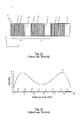
- Fig. 1e shows the intensity distribution, which in the dark field measurement of the reflections on a scattering region 3 on the sensor surface 102 of a sensor device 101 according to Fig. 1a along the longitudinal direction X would be measurable.
- the number of linear depressions 5 per scattering region 3 is eight in each case.
- the horizontal lines indicated by the reference numeral 5 ' represent regions on the sensor surface 102, which corresponds in each case to an optical image of the depressions 5 which could be produced on the sensor surface 102 by means of the imaging device 104 of the sensor device 101.
- Each line 5 marks the extension of an optical image of one of the recesses 5 on the sensor surface 102 in the longitudinal direction X.
- the traversed line provided with the reference I indicates the spatial distribution of the intensity of the light impinging on the sensor surface 102 in a dark field measurement.
- the incremental track 2 is illuminated with two different (not shown in the figures) light sources, the light sources are arranged such that the incremental track 2 on one side of the scale by means of the two light sources from two different directions symmetrical to a plane is illuminated, which extends perpendicular to the longitudinal direction X of the scale and parallel to the longitudinal direction Y of the line-like depressions.
- Fig. 1d the intensity distribution I as a function of the location along the longitudinal direction X two distinct peaks. It leaves directly recognize that the intensity distribution, in contrast to transmitted-light microscopy (corresponding to Fig. La-1c), by no means corresponds to a rectangular signal. If a conventional sensor device 101 is used to scan the scale 2, it could be due to a superposition of the signal Fig.
- a dimensional standard is specified by the present invention, with which a particularly high-contrast, in particular rectangular illumination of the sensor surface can be achieved.
- the interpolability of the sensor signal is to be improved by the dimensional standard according to the invention.
- inventive dimensional embodiment 10 has at least one first incremental track 20, which in the longitudinal direction X alternately arranged scattering regions 23 and mirror regions 24 includes.
- the mirror regions 24 are in turn formed with a substantially smooth surface which reflects reflecting light in a mirror-like manner.
- the scattering regions 23 are provided with at least two, in particular four, line-like recesses 26-1, 26-2, 26-3, 26-4.
- the width of one of the scattering regions 23 together with the width of one of the mirror regions 24 is determined by the pitch P.
- the pitch P is a constant which is determined by the sensor device to be used.
- Fig. 2a shown linear recesses 26-1, 26-2, 26-3, 26-4 constructed by substantially round recesses 25 which are arranged overlapping so that the at least two parallel, line-like recesses 26-1, 26-2, 26- 3, 26-4 arise.
- the line-like depressions 26-1, 26-2, 26-3, 26-4 are aligned in particular perpendicularly with respect to the longitudinal direction X of the incremental track 20 by the round depression grooves 25 overlapping in the transverse direction Y.
- the dimensional scale according to the invention is not limited to the special design of the line-like recesses 26-1, 26-2, 26-3, 26-4 of a plurality of round recesses. Rather, these can also be generated in a single step as continuous trenches ( Fig. 9b ).
- the dimensional standard 10 according to the invention also differs from the prior art in that the width of the scattering region 23 is less than half the pitch P. Due to the thus shortened scattering regions 23, an intensity distribution of the scattered light (13, Fig. 2b ) which outputs the rectangular signal 200 Fig. 1c comes very close. An example of this will be made later with reference to the preferred embodiment Fig. 4 described.
- the invention is generally not limited to a specific number of depressions per scattering area 23 as long as at least two depressions are present.
- To the top of the number of line-like depressions is also generally set no limit, as long as the width of the scattering range 23 does not make up more than 50% of the pitch.
- FIG. 2b A cross section through the in Fig. 2a illustrated embodiment, in the longitudinal direction X, is in the Fig. 2b to recognize. From this, the reflection effect of the individual regions 23 and 24 can be seen schematically.
- Fig. 2b indicates, in the present example to illuminate the individual areas 23 and 24 of the incremental track 20, two light sources 105-1 and 105-2 are provided which each generate light that falls at an angle ⁇ to the areas 23 and 24 of the incremental track 20 in that the areas 23 and 24 of the incremental track 20 are illuminated symmetrically from two different directions to a plane which is perpendicular to the longitudinal direction X of the scale 20 and parallel to the longitudinal direction Y of the line-like depressions 26-1, 26-2, 26-3 , 26-4 extends (in Fig.
- the straight dashed lines represent light beams corresponding to the light incident on the incremental track 20 from the light source 105-1, and the straight dash-dotted lines are light beams corresponding to the light incident on the incremental track 20 from the light source 105-2 correspond).
- the angle ⁇ is chosen such that the light reflected at the mirror regions 24 does not strike the sensor surface 102 and thus can not be detected by the sensor device 101.
- incident light is diffusely reflected by the line-like recesses 26-1, 26-2, 26-3, and 26-4 of the scattering regions 23, so that a substantially non-directional radiation 13 is thrown back onto the sensor device 101.
- substantially non-directional radiation 13 is intended to express that, although the radiation 13 is diffuse, it nevertheless has a preferred direction. This is due to the fact that a preferred direction for the diffuse reflection is achieved by the line-like formation of the depressions 26-1, 26-2, 26-3, 26-4, which is perpendicular to the line-like depressions 26-1, 26-2, 26-3, 26-4, ie in the longitudinal direction X of the incremental track 20 runs. A scattering of the incident light beam in the transverse direction Y of the incremental track, however, is negligible.
- a directional radiation 14 which preferably has no influence on the sensor signal.
- the sensor lens is in particular perpendicular to the illuminated position of the incremental track 20, whereby the obliquely reflected, directed radiation 14 can not reach the sensor.
- Only the diffusely reflected, substantially non-directional radiation 13 also has vertical radiation components which can reach the sensor optics.
- This measurement principle is also used in dark field microscopy. Thus, only the line-like recesses 26-1, 26-2, 26-3, 26-4 of the scattering regions 23 are detected as bright spots with the sensor signal.
- the mirror areas 24, however, are preferably completely dark, ie the dark field sensor can detect no light radiation here.
- Such a sensor is for example the application EP 2 381 222 A1 refer to.
- the present invention is therefore based on the finding that the contrast and the interpolability of the sensor signal can be significantly increased if the width of the scattering regions 23 is reduced. It is particularly advantageous if the scattering regions 23, in the longitudinal direction X of the incremental track 20, have a width which is less than or equal to a width of the mirror regions 24, ie less than or equal to half of the pitch P. Fig. 2a further shows that the width of the scattering regions 23 is limited by the two outward line depressions (26-1 and 26-4).
- the width of the scattering region 23 in each case should be greater than 1/10 of the pitch P.
- the scattering regions 23 according to the invention should preferably have a width which corresponds to 30% to 45%, preferably 35% to 40%, and in particular about 38%, of the width of the scattering regions 23. As a result, an optimal contrast of the sensor signal is ensured.
- the Fig. 3 shows the contrast of the sensor signal as a function of the width of the scattering regions 23.
- the representation of Fig. 3 shows the width of the scattering areas in relation to the pitch.
- the variables B 23 and B 24 are used to express the width of the respective scattering regions 23 or mirror regions 24.
- the sensor device 101 When determining the contrast, it is assumed that the sensor device 101 generates a sensor signal S during a movement of the sensor device 101 in the longitudinal direction X, which, depending on the position of the sensor device 101, essentially periodically between a maximum signal value Smax and a minimum Signal value Smin varies.
- the contrast K usually assumes a value between 0 and 1. If appropriate, the sensor device 101 can be set up in such a way that the sensor device 101 outputs the value 0 for the sensor signal S if the illumination of the material measure is switched off.
- the Width of the scattering regions 23 should preferably be in a range between 35% and 40% of the pitch.
- FIG Fig. 4 A schematic view of this preferred embodiment is shown in FIG Fig. 4 shown as a top view.
- the width of the scattering was 39 ⁇ m in experiment V5, which is about 38% of the width of the pitch.
- Three line-like depressions per scattering area 23 were provided, which were arranged at a distance of 7.5 ⁇ m from each other.
- the length of the three line-like depressions was approximately 1 mm, the depressions each having a depth of approximately 0.5 ⁇ m and a width of approximately 8 ⁇ m.
- the laser parameters required for this purpose are explained in more detail below with reference to the method according to the invention.
- Fig. 4 2 which schematically illustrates the experimental arrangement V5 likewise has a first incremental track 20, which is subdivided into scattering regions 23 and mirror regions 24.
- the scattering regions 23 according to the second embodiment have in particular three line-like recesses 26-1, 26-2 and 26-3.
- the present invention is not limited to the number of wells shown in the embodiments.
- the distances A of the line-like depressions 26-1, 26-2, 26-3 should be between 6 ⁇ m and 9 ⁇ m, in particular 7.5 ⁇ m.
- Words have the scattering regions 23 according to the second embodiment, at least three parallel line-like depressions 26-1, 26-2, 26-3, which is aligned perpendicular to the longitudinal direction X of the incremental 20 and at a distance A of 6 microns to 9 microns, in particular 7.5 microns apart.
- the representation according to Fig. 5 can the intensity distribution I in the dark field of the scattering regions 23 according to the preferred embodiment of Fig. 4 be removed.
- the intensity distribution I is determined on the condition that the incremental track 20 is in accordance with Fig. 4 by means of an arrangement of two light sources 105-1 and 105-2, respectively Fig. 2b with light, which is analogous to Fig. 2b is incident on the incremental track 20 at an angle ⁇ , is illuminated and the sensor device 101 according to Fig. 2b for scanning the incremental track 20 is available. It is analogous to the situation according to Fig. 2b Provided that only light can be detected by the sensor device 101, which light is diffused at the recesses 26-1, 26-2 and 26-3 of the scattering regions.
- the solid line provided with the reference I indicates the spatial distribution of the intensity produced in a dark field measurement the incident on the sensor surface 102 light as a function of the location along the longitudinal direction X on.
- the intensity distribution I out Fig. 5 in contrast to the conventional intensity distribution Fig. 1e , the rectangular illumination of the sensor surface according to Fig. 1c (Reference numeral 200) is already very close.
- the position of the lines 26-1 ', 26-2' and 26-3 'on the sensor surface 102 is indicated, in order to compare the arrangement of the lines 26-1', 26-2 'and 26-3' and the intensity distribution I to allow.
- the depressions 26-1, 26-2 and 26-3 form a scattering region 23 which scatters incident light in such a way that the intensity distribution shown arises, which covers in particular half, ie 50%, of the pitch.
- the sensor surface 102 of the sensor device 101 detects along the first half of the pitch in Fig. 5 shown intensity distribution, while along the second half of the pitch no stray light can be measured.
- the substantially rectangular intensity pattern obtained by the three line-like depressions 26 - 1, 26 - 2, 26 - 3 can be determined by the in - Fig. 1b converted, conventional sensor surface into a sinusoidal sensor signal.
- a solution according to the third and fourth embodiments of the inventive dimensional embodiment 10 is in the FIGS. 6 and 7 and results from the knowledge that there is a partly very inhomogeneous light intensity distribution along the scattering regions 23.
- a particularly high light intensity is measured in the center (seen in the longitudinal direction X) of the scattering region 23, whereas the intensity at the edge regions of the scattering regions 23 is reduced (cf. Fig. 5 ).
- the line-like recesses 26-1, 26-2, 26-3, 26-4, 26-5 of the scattering regions 23 so form these have at least one, in particular three, shortened, linear depressions 26-2, 26-3, 26-4.
- the shortened line-like recesses 26-2, 26-3, 26-4 according to the FIGS. 6 and 7 each with a length, perpendicular to the longitudinal direction of the incremental track 20, which is shorter than a second length of further line-like recesses 26-1 and 26-5.
- the linear depressions 26-2, 26-3 and 26-4 located centrally within the scattering regions 23 are shortened in order to reduce the increased intensity in the center of the scattering regions.
- the shortened line-like depressions 26-2, 26-3, 26-4 have a starting and end regions which are shorter than the other, outer linear depressions 26-1, 26-5.
- the shortened line-like recesses 26-2, 26-3, 26-4 are, as shown in the figures, still centered along the longitudinal axis of the incremental track 20, but have a shortened length. Accordingly, the width of the incremental track 20 (in the transverse direction Y) according to this embodiment is defined in particular by the further line-like recesses 26-1, 26-5.
- the line-like recesses 26-1, 26-2, 26-3, 26-4, 26-5 also according to the fourth embodiment to Fig. 7 be educated.
- the shortened, line-like depressions 26-2, 26-3, 26-4 have a preferably central clearance 27 in relation to the further line-like depressions 26-1, 26-5.
- the central clearance 27 forms an interruption between an initial and end region of the shortened line-like recesses 26-2, 26-3, 26-4.
- the shortened line-like recesses 26-2, 26-3, 26-4 are divided into two and arranged at the edge regions of the incremental track 20. This also achieves a reduction in the intensity in the center of the scattering regions 23, as a result of which a particularly homogeneous, rectangular intensity distribution of the diffusely reflected light along the scattering regions 23 is achieved.
- the shortened line-like recesses 26-2, 26-3 and 26-4 may of course also include a combination of the types of shortened line-like recesses 26-2, 26-3 and 26-4 shown in the third and fourth embodiments.
- the number of line-like recesses according to the third and fourth embodiments can be varied as long as at least two line-like recesses are present and the width of the scattering regions 23 does not exceed half of the pitch P.
- the material measure 10 has, in addition to the at least one first incremental track 20, a reference track 30, which is arranged in particular parallel to the first incremental track 20.
- the reference track 30 is designed to specify an absolute position of a measuring head along the dimensional scale 10.
- the reference track 30 has in the longitudinal direction X alternately arranged reference scattering regions 33 and mirror regions 34.
- the reference scattering regions 33 like the scattering regions 23 of the first incremental trace 20, have a plurality of line-like depressions 36-1, 36-2, 36-3, 36-4, 36-5, 36-6, 36-7 and 36-8 on.
- the line-like recesses 36-1, 36-2, 36-3, 36-4, 36-5, 36-6, 36-7 and 36-8 are adapted to diffuse incident light diffusely.
- these, like the line-like recesses 26-1, 26-2, 26-3, 26-4 of the scattering regions 22, may be formed by an overlap of round recesses.
- the mirror regions 34 have a substantially smooth surface which, for example, corresponds to a polished metal surface.
- the reference scattering regions 33 are in this case in particular at known locations of the material measure 10, which a computing unit can use to determine the absolute position of the measuring head. For this purpose, the change in position of the measuring head relative to the reference scattering regions 33 of the reference track 30 is measured with the aid of the first incremental track 20.
- reference track 30 can be found in any of the aforementioned embodiments of the inventive dimensional embodiment 10 use.
- light with a wavelength in the range between 300 nm and 1.5 ⁇ m is suitable for illuminating the dimensional standards according to the invention, ie the extent of one of the line-like depressions 26-1, 26-2, 26-3, 26-4 or 26-5 of one of the scattering regions 23 in the longitudinal direction X of the respective dimensional scale may be many times greater than the wavelength of the light used to illuminate the respective dimensional scale.
- the size of the angle ⁇ , below which the light used for illumination can fall on the respective scale is relatively uncritical with regard to the size of the sensor signals, so that the angle ⁇ can be varied in a relatively large range, for example in a range between 30 ° and 70 °.
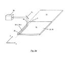
- the representation according to FIG. 9a is a schematic representation of the method for applying a dimensional scale 10 on a metal surface 11 refer.
- a pulsed laser 50 is provided for introducing the substantially round recesses 25.
- each of the depressions 25 is produced by arranging the essentially round beam 40 at different points along the metal surface 11 for the duration of a laser pulse.
- the metal surface 11 is melted and partially evaporated, whereby the substantially circular recesses 25 arise.
- a mirror 51 is adjusted perpendicular to the longitudinal direction between the pulses of the pulse laser 50 so that the beam 40 is moved along the axis S. In the new travel position, heat energy is in turn introduced into the metal surface 11 for the duration of a laser pulse in order to produce a further, round depression 25.
- the beam 40 is moved as far along the axis S between the individual pulses, so that the substantially circular recesses 25 overlap.
- the essentially round recesses 25 overlap in such a way that one of the at least two line-like recesses 26-1 or 36-1 arises, which is aligned substantially perpendicular to the longitudinal direction X of the incremental track 20 or the reference track 30. This process is of course repeated for all desired line-like recesses 26-1, 26-2, 26-3, 26-4 and 26-5.
- the diameter of the beam 40 is selected to produce the round recesses 25 such that the recesses 25 have a diameter of 3.5 microns to 12 microns, preferably 6 microns to 9 microns, and more preferably about 7 microns.
- line-like depressions are produced with a width of about 8 microns, which correspond to the width of the preferred embodiment V5.
- the beam 40 of the laser 50 is moved further by means of the mirror 51, so that an overlap of the substantially round recesses 25 of at least 75% is formed. In other words, by the movement of the beam 40, the line-like recess 26-1 or 36-1 each extended by a maximum of 25% of the diameter of the round recesses 25.
- the preferred laser parameters for the above process can be found in Table 2 below and relate to making line-like pits of about 1 mm: ⁇ b> Table 2 ⁇ / b> laser power about 0.25W pulse rate about 60 kHz Energy per pulse about 4.3 ⁇ J traversing about 100mm / s Pulses per linear. deepening about 600 Energy per linear depression about 2.5 mJ
- diode-pumped solid-state lasers such as vanadate laser, with a wavelength of about 355 nm are suitable.
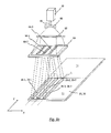
- the line-like recesses 26-1, 26-2, 26-3, 26-4, 26-5 and 36-1, 36-2, 36-3, 36-4, 36- 5, 36-6 of the inventive dimensional embodiment 10 need not necessarily consist of a plurality of round recesses 25. Rather, the individual linear depressions can each be manufactured with one working step. An example of this is shown schematically in the illustration Fig. 9b shown.
- the laser beam 40 may be directed onto a masking element 64 via imaging devices 60 and 62, for example, prior to applying the metal surface.
- the masking element 64 has at least two line-like openings 66-1, 66-2, 66-3, wherein an image of the line-like openings 66-1, 66-2, 66-3 is imaged onto the metal surface 11 by the laser beam.
- the image of the line-like openings 66-1, 66-2, 66-3 is configured so that at least one scattering area 23 consists of at least two line-like recesses 26-1, 26-2, 26-3, 36-1, 36-2, 36-3 is created.
- the line-like depressions of the material measure 10 are applied by etching or embossing on the metal surface.
- the line-like depressions thus produced could have the advantageous arrangements, which play the nossbei according to the FIGS. 2a to 7 to achieve maximum contrast with sufficient interpolability.
- the present invention is not limited to the feature combinations shown in the embodiments. Rather, the present invention results from a combination of all the features disclosed herein.
Priority Applications (7)
| Application Number | Priority Date | Filing Date | Title |
|---|---|---|---|
| EP20130405121 EP2865998A1 (fr) | 2013-10-23 | 2013-10-23 | Mesure matérialisée pour capteurs incrémentiels et son procédé de fabrication |
| CN201480058037.8A CN105659057B (zh) | 2013-10-23 | 2014-10-20 | 增量编码器的刻度及其制造方法 |
| EP14803035.6A EP3060887B1 (fr) | 2013-10-23 | 2014-10-20 | Échelle de mesure pour capteur incrémentiel et son procédé de fabrication |
| KR1020167008835A KR20160077053A (ko) | 2013-10-23 | 2014-10-20 | 증분 인코더용 측정 소자 및 그 제조 방법 |
| PCT/CH2014/000155 WO2015058313A1 (fr) | 2013-10-23 | 2014-10-20 | Échelle de mesure pour codeurs incrémentaux et procédé de fabrication de celui-ci |
| JP2016549601A JP6501785B2 (ja) | 2013-10-23 | 2014-10-20 | インクリメンタルエンコーダ用のスケール本体及びこのスケール本体を製造するための方法 |
| TW103136401A TWI655410B (zh) | 2013-10-23 | 2014-10-22 | 增量編碼器之刻度及其製造方法 |
Applications Claiming Priority (1)
| Application Number | Priority Date | Filing Date | Title |
|---|---|---|---|
| EP20130405121 EP2865998A1 (fr) | 2013-10-23 | 2013-10-23 | Mesure matérialisée pour capteurs incrémentiels et son procédé de fabrication |
Publications (1)
| Publication Number | Publication Date |
|---|---|
| EP2865998A1 true EP2865998A1 (fr) | 2015-04-29 |
Family
ID=49518905
Family Applications (2)
| Application Number | Title | Priority Date | Filing Date |
|---|---|---|---|
| EP20130405121 Withdrawn EP2865998A1 (fr) | 2013-10-23 | 2013-10-23 | Mesure matérialisée pour capteurs incrémentiels et son procédé de fabrication |
| EP14803035.6A Active EP3060887B1 (fr) | 2013-10-23 | 2014-10-20 | Échelle de mesure pour capteur incrémentiel et son procédé de fabrication |
Family Applications After (1)
| Application Number | Title | Priority Date | Filing Date |
|---|---|---|---|
| EP14803035.6A Active EP3060887B1 (fr) | 2013-10-23 | 2014-10-20 | Échelle de mesure pour capteur incrémentiel et son procédé de fabrication |
Country Status (6)
| Country | Link |
|---|---|
| EP (2) | EP2865998A1 (fr) |
| JP (1) | JP6501785B2 (fr) |
| KR (1) | KR20160077053A (fr) |
| CN (1) | CN105659057B (fr) |
| TW (1) | TWI655410B (fr) |
| WO (1) | WO2015058313A1 (fr) |
Families Citing this family (2)
| Publication number | Priority date | Publication date | Assignee | Title |
|---|---|---|---|---|
| JP2024054841A (ja) | 2022-10-05 | 2024-04-17 | シュネーベルガー・ホールディング・アクチエンゲゼルシャフト | スケール本体をリニアプロファイルレールガイドのガイドキャリッジの表面に形成するための方法、リニアエンコーダのためのスケール本体及びリニアエンコーダ |
| JP2024054840A (ja) | 2022-10-05 | 2024-04-17 | シュネーベルガー・ホールディング・アクチエンゲゼルシャフト | スケール本体をリニアプロファイルレールガイドのガイドレールの表面に形成するための方法、リニアエンコーダのためのスケール本体及びリニアエンコーダ |
Citations (6)
| Publication number | Priority date | Publication date | Assignee | Title |
|---|---|---|---|---|
| DE2515574A1 (de) | 1974-04-10 | 1975-10-30 | Genevoise Instr Physique | Praezisionsmasstab aus metall |
| DE19608937A1 (de) | 1995-03-10 | 1996-09-12 | Heidenhain Gmbh Dr Johannes | Verfahren zum Herstellen eines Markierungsträgers |
| DE10226444A1 (de) * | 2002-06-13 | 2004-01-15 | Samland, Thomas, Dipl.-Math. | Vorrichtung und Verfahren zur mikrooptischen Positionsmessung |
| DE102007007311A1 (de) | 2006-02-12 | 2007-08-30 | Thomas Samland | Abtasteinheit für eine Positionsmesseinrichtung zur Detektion von optischen Maßverkörperungen sowie entsprechende Positionsmesseinrichtung |
| DE102007024593A1 (de) * | 2007-05-25 | 2008-11-27 | Dr. Johannes Heidenhain Gmbh | Maßstab für eine Positionsmesseinrichtung und Positionsmesseinrichtung |
| EP2381222A1 (fr) | 2010-04-22 | 2011-10-26 | Schneeberger Holding AG | Système de guidage doté de corpsen déplacement relatif et dispositif de détermination d'une position à l'aide du balayage optique d'une échelle de mesure. |
Family Cites Families (8)
| Publication number | Priority date | Publication date | Assignee | Title |
|---|---|---|---|---|
| JP2005014059A (ja) * | 2003-06-26 | 2005-01-20 | Ricoh Co Ltd | 超短パルスレーザ加工法及び加工装置並びに構造体 |
| US7903336B2 (en) * | 2005-10-11 | 2011-03-08 | Gsi Group Corporation | Optical metrological scale and laser-based manufacturing method therefor |
| JP2009019876A (ja) * | 2005-10-28 | 2009-01-29 | Mitsubishi Electric Corp | 光学式絶対値エンコーダ |
| JP2009198318A (ja) * | 2008-02-21 | 2009-09-03 | Mitsutoyo Corp | 光電式エンコーダ |
| JP5119192B2 (ja) * | 2009-03-31 | 2013-01-16 | 富士フイルム株式会社 | 光学式位置検出器及び光学装置 |
| JP5378316B2 (ja) * | 2009-07-29 | 2013-12-25 | 山洋電気株式会社 | 光学式エンコーダ装置 |
| TW201241399A (en) * | 2011-04-07 | 2012-10-16 | xi-ming Xu | Laser measurement device |
| JP5993564B2 (ja) * | 2011-07-13 | 2016-09-14 | 新日本無線株式会社 | 反射型フォトセンサを用いた位置検出装置 |
-
2013
- 2013-10-23 EP EP20130405121 patent/EP2865998A1/fr not_active Withdrawn
-
2014
- 2014-10-20 WO PCT/CH2014/000155 patent/WO2015058313A1/fr active Application Filing
- 2014-10-20 EP EP14803035.6A patent/EP3060887B1/fr active Active
- 2014-10-20 KR KR1020167008835A patent/KR20160077053A/ko not_active Application Discontinuation
- 2014-10-20 JP JP2016549601A patent/JP6501785B2/ja active Active
- 2014-10-20 CN CN201480058037.8A patent/CN105659057B/zh active Active
- 2014-10-22 TW TW103136401A patent/TWI655410B/zh active
Patent Citations (7)
| Publication number | Priority date | Publication date | Assignee | Title |
|---|---|---|---|---|
| DE2515574A1 (de) | 1974-04-10 | 1975-10-30 | Genevoise Instr Physique | Praezisionsmasstab aus metall |
| FR2267538A1 (fr) * | 1974-04-10 | 1975-11-07 | Genevoise Instr Physique | |
| DE19608937A1 (de) | 1995-03-10 | 1996-09-12 | Heidenhain Gmbh Dr Johannes | Verfahren zum Herstellen eines Markierungsträgers |
| DE10226444A1 (de) * | 2002-06-13 | 2004-01-15 | Samland, Thomas, Dipl.-Math. | Vorrichtung und Verfahren zur mikrooptischen Positionsmessung |
| DE102007007311A1 (de) | 2006-02-12 | 2007-08-30 | Thomas Samland | Abtasteinheit für eine Positionsmesseinrichtung zur Detektion von optischen Maßverkörperungen sowie entsprechende Positionsmesseinrichtung |
| DE102007024593A1 (de) * | 2007-05-25 | 2008-11-27 | Dr. Johannes Heidenhain Gmbh | Maßstab für eine Positionsmesseinrichtung und Positionsmesseinrichtung |
| EP2381222A1 (fr) | 2010-04-22 | 2011-10-26 | Schneeberger Holding AG | Système de guidage doté de corpsen déplacement relatif et dispositif de détermination d'une position à l'aide du balayage optique d'une échelle de mesure. |
Also Published As
| Publication number | Publication date |
|---|---|
| TWI655410B (zh) | 2019-04-01 |
| CN105659057A (zh) | 2016-06-08 |
| JP6501785B2 (ja) | 2019-04-17 |
| WO2015058313A1 (fr) | 2015-04-30 |
| EP3060887B1 (fr) | 2017-07-26 |
| TW201530099A (zh) | 2015-08-01 |
| CN105659057B (zh) | 2018-07-06 |
| JP2016538571A (ja) | 2016-12-08 |
| EP3060887A1 (fr) | 2016-08-31 |
| KR20160077053A (ko) | 2016-07-01 |
Similar Documents
| Publication | Publication Date | Title |
|---|---|---|
| EP3321628B1 (fr) | Dispositif de mesure de coordonnées doté d'un capteur optique et procédé correspondant | |
| EP2796938B1 (fr) | Dispositif d'enregistrement d'une structure 3D d'un objet | |
| EP2149780A2 (fr) | Réseau de projection optique, caméra de mesure et procédé associé pour créer ce réseau de projection | |
| DE3901869A1 (de) | Optischer codierer | |
| DE102006062447A1 (de) | Verfahren und Vorrichtung zur Erfassung der dreidimensionalen Oberfläche eines Objekts, insbesondere eines Fahrzeugreifens | |
| EP2381222A1 (fr) | Système de guidage doté de corpsen déplacement relatif et dispositif de détermination d'une position à l'aide du balayage optique d'une échelle de mesure. | |
| EP2495525A1 (fr) | Procédé de vérification optique à l'aide d'un déroulement d'intensité | |
| DE102004010566A1 (de) | Tastkopf für ein Koordinatenmessgerät | |
| EP3060887B1 (fr) | Échelle de mesure pour capteur incrémentiel et son procédé de fabrication | |
| WO2004083911A1 (fr) | Microstructure et procede de production de microstructures | |
| WO2006045128A1 (fr) | Dispositif pour graver des plaques d'impression | |
| DE4408226C2 (de) | Meßeinrichtung zur prozeßgekoppelten Bestimmung der Rauheit technischer Oberflächen durch Auswertung di- oder polychromatischer Specklemuster | |
| EP3023737A1 (fr) | Procede de mesure de surface sans contact avec correction de mesure | |
| DE202014010774U1 (de) | Massverkörperung für Inkrementalgeber | |
| DE10033263A1 (de) | Optische Positionsmesseinrichtung | |
| EP4350303A1 (fr) | Procédé d'application d'un corps de mesure sur une surface d'un rail de guidage linéaire, rail de mesure pour un codeur linéaire et codeur linéaire | |
| EP4350304A1 (fr) | Procédé d'application d'un mesure sur une surface d'un chariot de guidage d'un rail profilé linéaire, mesure matérialisée pour un codeur linéaire et un codeur linéaire | |
| EP1417519A1 (fr) | Determination optique de position ou de longueur | |
| DE102016204071A1 (de) | Verfahren zum Bestimmen der Lage des Fokus einer Laserstrahlanordnung und Verfahren zum Bearbeiten eines Werkstücks mit Laserstrahlung | |
| DE102004002683A1 (de) | Optische Positions- oder Längenbestimmung | |
| DE102019133009B4 (de) | Vorrichtung zum Beleuchten eines Werkstücks, Verfahren zu dessen Modifizierung und Verfahren zum Vermessen seiner Oberfläche | |
| DE2848204C2 (de) | Verfahren zum Ausmessen von Härteprüfeindrücken in Materialoberflächen, sowie Einrichtung zur Durchführung des Verfahrens | |
| DE19913013C2 (de) | Vorrichtung zum Erfassen eines Lichteinfalls und Meßeinrichtung für ein Lichtschnittverfahren mit dieser Vorrichtung | |
| DE4303161C2 (de) | Photoelektrisches Längen- bzw. Winkelmeßsystem mit einer Einrichtung zur Erfassung von Führungsfehlern | |
| DE19936181A1 (de) | Optische Positionsmeßeinrichtung |
Legal Events
| Date | Code | Title | Description |
|---|---|---|---|
| PUAI | Public reference made under article 153(3) epc to a published international application that has entered the european phase |
Free format text: ORIGINAL CODE: 0009012 |
|
| 17P | Request for examination filed |
Effective date: 20131023 |
|
| AK | Designated contracting states |
Kind code of ref document: A1 Designated state(s): AL AT BE BG CH CY CZ DE DK EE ES FI FR GB GR HR HU IE IS IT LI LT LU LV MC MK MT NL NO PL PT RO RS SE SI SK SM TR |
|
| AX | Request for extension of the european patent |
Extension state: BA ME |
|
| STAA | Information on the status of an ep patent application or granted ep patent |
Free format text: STATUS: THE APPLICATION IS DEEMED TO BE WITHDRAWN |
|
| 18D | Application deemed to be withdrawn |
Effective date: 20151030 |