EP2865913A1 - Vehicle controller - Google Patents
Vehicle controller Download PDFInfo
- Publication number
- EP2865913A1 EP2865913A1 EP12879304.9A EP12879304A EP2865913A1 EP 2865913 A1 EP2865913 A1 EP 2865913A1 EP 12879304 A EP12879304 A EP 12879304A EP 2865913 A1 EP2865913 A1 EP 2865913A1
- Authority
- EP
- European Patent Office
- Prior art keywords
- vehicle
- speed
- engine
- coasting control
- coasting
- Prior art date
- Legal status (The legal status is an assumption and is not a legal conclusion. Google has not performed a legal analysis and makes no representation as to the accuracy of the status listed.)
- Withdrawn
Links
Images


Classifications
-
- B—PERFORMING OPERATIONS; TRANSPORTING
- B60—VEHICLES IN GENERAL
- B60W—CONJOINT CONTROL OF VEHICLE SUB-UNITS OF DIFFERENT TYPE OR DIFFERENT FUNCTION; CONTROL SYSTEMS SPECIALLY ADAPTED FOR HYBRID VEHICLES; ROAD VEHICLE DRIVE CONTROL SYSTEMS FOR PURPOSES NOT RELATED TO THE CONTROL OF A PARTICULAR SUB-UNIT
- B60W30/00—Purposes of road vehicle drive control systems not related to the control of a particular sub-unit, e.g. of systems using conjoint control of vehicle sub-units, or advanced driver assistance systems for ensuring comfort, stability and safety or drive control systems for propelling or retarding the vehicle
- B60W30/18—Propelling the vehicle
- B60W30/18009—Propelling the vehicle related to particular drive situations
- B60W30/18072—Coasting
-
- F—MECHANICAL ENGINEERING; LIGHTING; HEATING; WEAPONS; BLASTING
- F16—ENGINEERING ELEMENTS AND UNITS; GENERAL MEASURES FOR PRODUCING AND MAINTAINING EFFECTIVE FUNCTIONING OF MACHINES OR INSTALLATIONS; THERMAL INSULATION IN GENERAL
- F16D—COUPLINGS FOR TRANSMITTING ROTATION; CLUTCHES; BRAKES
- F16D48/00—External control of clutches
- F16D48/02—Control by fluid pressure
-
- B—PERFORMING OPERATIONS; TRANSPORTING
- B60—VEHICLES IN GENERAL
- B60W—CONJOINT CONTROL OF VEHICLE SUB-UNITS OF DIFFERENT TYPE OR DIFFERENT FUNCTION; CONTROL SYSTEMS SPECIALLY ADAPTED FOR HYBRID VEHICLES; ROAD VEHICLE DRIVE CONTROL SYSTEMS FOR PURPOSES NOT RELATED TO THE CONTROL OF A PARTICULAR SUB-UNIT
- B60W10/00—Conjoint control of vehicle sub-units of different type or different function
- B60W10/02—Conjoint control of vehicle sub-units of different type or different function including control of driveline clutches
-
- B—PERFORMING OPERATIONS; TRANSPORTING
- B60—VEHICLES IN GENERAL
- B60W—CONJOINT CONTROL OF VEHICLE SUB-UNITS OF DIFFERENT TYPE OR DIFFERENT FUNCTION; CONTROL SYSTEMS SPECIALLY ADAPTED FOR HYBRID VEHICLES; ROAD VEHICLE DRIVE CONTROL SYSTEMS FOR PURPOSES NOT RELATED TO THE CONTROL OF A PARTICULAR SUB-UNIT
- B60W10/00—Conjoint control of vehicle sub-units of different type or different function
- B60W10/04—Conjoint control of vehicle sub-units of different type or different function including control of propulsion units
- B60W10/06—Conjoint control of vehicle sub-units of different type or different function including control of propulsion units including control of combustion engines
-
- B—PERFORMING OPERATIONS; TRANSPORTING
- B60—VEHICLES IN GENERAL
- B60W—CONJOINT CONTROL OF VEHICLE SUB-UNITS OF DIFFERENT TYPE OR DIFFERENT FUNCTION; CONTROL SYSTEMS SPECIALLY ADAPTED FOR HYBRID VEHICLES; ROAD VEHICLE DRIVE CONTROL SYSTEMS FOR PURPOSES NOT RELATED TO THE CONTROL OF A PARTICULAR SUB-UNIT
- B60W10/00—Conjoint control of vehicle sub-units of different type or different function
- B60W10/10—Conjoint control of vehicle sub-units of different type or different function including control of change-speed gearings
-
- B—PERFORMING OPERATIONS; TRANSPORTING
- B60—VEHICLES IN GENERAL
- B60W—CONJOINT CONTROL OF VEHICLE SUB-UNITS OF DIFFERENT TYPE OR DIFFERENT FUNCTION; CONTROL SYSTEMS SPECIALLY ADAPTED FOR HYBRID VEHICLES; ROAD VEHICLE DRIVE CONTROL SYSTEMS FOR PURPOSES NOT RELATED TO THE CONTROL OF A PARTICULAR SUB-UNIT
- B60W30/00—Purposes of road vehicle drive control systems not related to the control of a particular sub-unit, e.g. of systems using conjoint control of vehicle sub-units, or advanced driver assistance systems for ensuring comfort, stability and safety or drive control systems for propelling or retarding the vehicle
- B60W30/18—Propelling the vehicle
- B60W30/188—Controlling power parameters of the driveline, e.g. determining the required power
-
- F—MECHANICAL ENGINEERING; LIGHTING; HEATING; WEAPONS; BLASTING
- F16—ENGINEERING ELEMENTS AND UNITS; GENERAL MEASURES FOR PRODUCING AND MAINTAINING EFFECTIVE FUNCTIONING OF MACHINES OR INSTALLATIONS; THERMAL INSULATION IN GENERAL
- F16D—COUPLINGS FOR TRANSMITTING ROTATION; CLUTCHES; BRAKES
- F16D1/00—Couplings for rigidly connecting two coaxial shafts or other movable machine elements
- F16D1/10—Quick-acting couplings in which the parts are connected by simply bringing them together axially
- F16D1/101—Quick-acting couplings in which the parts are connected by simply bringing them together axially without axial retaining means rotating with the coupling
-
- F—MECHANICAL ENGINEERING; LIGHTING; HEATING; WEAPONS; BLASTING
- F16—ENGINEERING ELEMENTS AND UNITS; GENERAL MEASURES FOR PRODUCING AND MAINTAINING EFFECTIVE FUNCTIONING OF MACHINES OR INSTALLATIONS; THERMAL INSULATION IN GENERAL
- F16D—COUPLINGS FOR TRANSMITTING ROTATION; CLUTCHES; BRAKES
- F16D27/00—Magnetically- or electrically- actuated clutches; Control or electric circuits therefor
- F16D27/02—Magnetically- or electrically- actuated clutches; Control or electric circuits therefor with electromagnets incorporated in the clutch, i.e. with collecting rings
-
- F—MECHANICAL ENGINEERING; LIGHTING; HEATING; WEAPONS; BLASTING
- F16—ENGINEERING ELEMENTS AND UNITS; GENERAL MEASURES FOR PRODUCING AND MAINTAINING EFFECTIVE FUNCTIONING OF MACHINES OR INSTALLATIONS; THERMAL INSULATION IN GENERAL
- F16D—COUPLINGS FOR TRANSMITTING ROTATION; CLUTCHES; BRAKES
- F16D48/00—External control of clutches
- F16D48/06—Control by electric or electronic means, e.g. of fluid pressure
-
- F—MECHANICAL ENGINEERING; LIGHTING; HEATING; WEAPONS; BLASTING
- F16—ENGINEERING ELEMENTS AND UNITS; GENERAL MEASURES FOR PRODUCING AND MAINTAINING EFFECTIVE FUNCTIONING OF MACHINES OR INSTALLATIONS; THERMAL INSULATION IN GENERAL
- F16H—GEARING
- F16H61/00—Control functions within control units of change-speed- or reversing-gearings for conveying rotary motion ; Control of exclusively fluid gearing, friction gearing, gearings with endless flexible members or other particular types of gearing
- F16H61/02—Control functions within control units of change-speed- or reversing-gearings for conveying rotary motion ; Control of exclusively fluid gearing, friction gearing, gearings with endless flexible members or other particular types of gearing characterised by the signals used
-
- F—MECHANICAL ENGINEERING; LIGHTING; HEATING; WEAPONS; BLASTING
- F16—ENGINEERING ELEMENTS AND UNITS; GENERAL MEASURES FOR PRODUCING AND MAINTAINING EFFECTIVE FUNCTIONING OF MACHINES OR INSTALLATIONS; THERMAL INSULATION IN GENERAL
- F16H—GEARING
- F16H61/00—Control functions within control units of change-speed- or reversing-gearings for conveying rotary motion ; Control of exclusively fluid gearing, friction gearing, gearings with endless flexible members or other particular types of gearing
- F16H61/21—Providing engine brake control
-
- B—PERFORMING OPERATIONS; TRANSPORTING
- B60—VEHICLES IN GENERAL
- B60W—CONJOINT CONTROL OF VEHICLE SUB-UNITS OF DIFFERENT TYPE OR DIFFERENT FUNCTION; CONTROL SYSTEMS SPECIALLY ADAPTED FOR HYBRID VEHICLES; ROAD VEHICLE DRIVE CONTROL SYSTEMS FOR PURPOSES NOT RELATED TO THE CONTROL OF A PARTICULAR SUB-UNIT
- B60W30/00—Purposes of road vehicle drive control systems not related to the control of a particular sub-unit, e.g. of systems using conjoint control of vehicle sub-units, or advanced driver assistance systems for ensuring comfort, stability and safety or drive control systems for propelling or retarding the vehicle
- B60W30/18—Propelling the vehicle
- B60W30/18009—Propelling the vehicle related to particular drive situations
- B60W30/18072—Coasting
- B60W2030/1809—Without torque flow between driveshaft and engine, e.g. with clutch disengaged or transmission in neutral
-
- B—PERFORMING OPERATIONS; TRANSPORTING
- B60—VEHICLES IN GENERAL
- B60W—CONJOINT CONTROL OF VEHICLE SUB-UNITS OF DIFFERENT TYPE OR DIFFERENT FUNCTION; CONTROL SYSTEMS SPECIALLY ADAPTED FOR HYBRID VEHICLES; ROAD VEHICLE DRIVE CONTROL SYSTEMS FOR PURPOSES NOT RELATED TO THE CONTROL OF A PARTICULAR SUB-UNIT
- B60W2510/00—Input parameters relating to a particular sub-units
- B60W2510/06—Combustion engines, Gas turbines
- B60W2510/0638—Engine speed
-
- B—PERFORMING OPERATIONS; TRANSPORTING
- B60—VEHICLES IN GENERAL
- B60W—CONJOINT CONTROL OF VEHICLE SUB-UNITS OF DIFFERENT TYPE OR DIFFERENT FUNCTION; CONTROL SYSTEMS SPECIALLY ADAPTED FOR HYBRID VEHICLES; ROAD VEHICLE DRIVE CONTROL SYSTEMS FOR PURPOSES NOT RELATED TO THE CONTROL OF A PARTICULAR SUB-UNIT
- B60W2520/00—Input parameters relating to overall vehicle dynamics
- B60W2520/10—Longitudinal speed
- B60W2520/105—Longitudinal acceleration
-
- B—PERFORMING OPERATIONS; TRANSPORTING
- B60—VEHICLES IN GENERAL
- B60W—CONJOINT CONTROL OF VEHICLE SUB-UNITS OF DIFFERENT TYPE OR DIFFERENT FUNCTION; CONTROL SYSTEMS SPECIALLY ADAPTED FOR HYBRID VEHICLES; ROAD VEHICLE DRIVE CONTROL SYSTEMS FOR PURPOSES NOT RELATED TO THE CONTROL OF A PARTICULAR SUB-UNIT
- B60W2520/00—Input parameters relating to overall vehicle dynamics
- B60W2520/12—Lateral speed
- B60W2520/125—Lateral acceleration
-
- B—PERFORMING OPERATIONS; TRANSPORTING
- B60—VEHICLES IN GENERAL
- B60W—CONJOINT CONTROL OF VEHICLE SUB-UNITS OF DIFFERENT TYPE OR DIFFERENT FUNCTION; CONTROL SYSTEMS SPECIALLY ADAPTED FOR HYBRID VEHICLES; ROAD VEHICLE DRIVE CONTROL SYSTEMS FOR PURPOSES NOT RELATED TO THE CONTROL OF A PARTICULAR SUB-UNIT
- B60W2540/00—Input parameters relating to occupants
- B60W2540/10—Accelerator pedal position
- B60W2540/106—Rate of change
-
- B—PERFORMING OPERATIONS; TRANSPORTING
- B60—VEHICLES IN GENERAL
- B60W—CONJOINT CONTROL OF VEHICLE SUB-UNITS OF DIFFERENT TYPE OR DIFFERENT FUNCTION; CONTROL SYSTEMS SPECIALLY ADAPTED FOR HYBRID VEHICLES; ROAD VEHICLE DRIVE CONTROL SYSTEMS FOR PURPOSES NOT RELATED TO THE CONTROL OF A PARTICULAR SUB-UNIT
- B60W2540/00—Input parameters relating to occupants
- B60W2540/18—Steering angle
-
- B—PERFORMING OPERATIONS; TRANSPORTING
- B60—VEHICLES IN GENERAL
- B60W—CONJOINT CONTROL OF VEHICLE SUB-UNITS OF DIFFERENT TYPE OR DIFFERENT FUNCTION; CONTROL SYSTEMS SPECIALLY ADAPTED FOR HYBRID VEHICLES; ROAD VEHICLE DRIVE CONTROL SYSTEMS FOR PURPOSES NOT RELATED TO THE CONTROL OF A PARTICULAR SUB-UNIT
- B60W2552/00—Input parameters relating to infrastructure
- B60W2552/15—Road slope
-
- F—MECHANICAL ENGINEERING; LIGHTING; HEATING; WEAPONS; BLASTING
- F16—ENGINEERING ELEMENTS AND UNITS; GENERAL MEASURES FOR PRODUCING AND MAINTAINING EFFECTIVE FUNCTIONING OF MACHINES OR INSTALLATIONS; THERMAL INSULATION IN GENERAL
- F16D—COUPLINGS FOR TRANSMITTING ROTATION; CLUTCHES; BRAKES
- F16D2500/00—External control of clutches by electric or electronic means
- F16D2500/10—System to be controlled
- F16D2500/104—Clutch
- F16D2500/10406—Clutch position
- F16D2500/10412—Transmission line of a vehicle
-
- F—MECHANICAL ENGINEERING; LIGHTING; HEATING; WEAPONS; BLASTING
- F16—ENGINEERING ELEMENTS AND UNITS; GENERAL MEASURES FOR PRODUCING AND MAINTAINING EFFECTIVE FUNCTIONING OF MACHINES OR INSTALLATIONS; THERMAL INSULATION IN GENERAL
- F16D—COUPLINGS FOR TRANSMITTING ROTATION; CLUTCHES; BRAKES
- F16D2500/00—External control of clutches by electric or electronic means
- F16D2500/30—Signal inputs
- F16D2500/304—Signal inputs from the clutch
- F16D2500/3042—Signal inputs from the clutch from the output shaft
- F16D2500/30426—Speed of the output shaft
-
- F—MECHANICAL ENGINEERING; LIGHTING; HEATING; WEAPONS; BLASTING
- F16—ENGINEERING ELEMENTS AND UNITS; GENERAL MEASURES FOR PRODUCING AND MAINTAINING EFFECTIVE FUNCTIONING OF MACHINES OR INSTALLATIONS; THERMAL INSULATION IN GENERAL
- F16D—COUPLINGS FOR TRANSMITTING ROTATION; CLUTCHES; BRAKES
- F16D2500/00—External control of clutches by electric or electronic means
- F16D2500/30—Signal inputs
- F16D2500/308—Signal inputs from the transmission
- F16D2500/3081—Signal inputs from the transmission from the input shaft
- F16D2500/30816—Speed of the input shaft
-
- F—MECHANICAL ENGINEERING; LIGHTING; HEATING; WEAPONS; BLASTING
- F16—ENGINEERING ELEMENTS AND UNITS; GENERAL MEASURES FOR PRODUCING AND MAINTAINING EFFECTIVE FUNCTIONING OF MACHINES OR INSTALLATIONS; THERMAL INSULATION IN GENERAL
- F16D—COUPLINGS FOR TRANSMITTING ROTATION; CLUTCHES; BRAKES
- F16D2500/00—External control of clutches by electric or electronic means
- F16D2500/30—Signal inputs
- F16D2500/308—Signal inputs from the transmission
- F16D2500/3082—Signal inputs from the transmission from the output shaft
- F16D2500/30825—Speed of the output shaft
-
- F—MECHANICAL ENGINEERING; LIGHTING; HEATING; WEAPONS; BLASTING
- F16—ENGINEERING ELEMENTS AND UNITS; GENERAL MEASURES FOR PRODUCING AND MAINTAINING EFFECTIVE FUNCTIONING OF MACHINES OR INSTALLATIONS; THERMAL INSULATION IN GENERAL
- F16D—COUPLINGS FOR TRANSMITTING ROTATION; CLUTCHES; BRAKES
- F16D2500/00—External control of clutches by electric or electronic means
- F16D2500/30—Signal inputs
- F16D2500/31—Signal inputs from the vehicle
- F16D2500/3108—Vehicle speed
-
- F—MECHANICAL ENGINEERING; LIGHTING; HEATING; WEAPONS; BLASTING
- F16—ENGINEERING ELEMENTS AND UNITS; GENERAL MEASURES FOR PRODUCING AND MAINTAINING EFFECTIVE FUNCTIONING OF MACHINES OR INSTALLATIONS; THERMAL INSULATION IN GENERAL
- F16D—COUPLINGS FOR TRANSMITTING ROTATION; CLUTCHES; BRAKES
- F16D2500/00—External control of clutches by electric or electronic means
- F16D2500/30—Signal inputs
- F16D2500/314—Signal inputs from the user
- F16D2500/31406—Signal inputs from the user input from pedals
- F16D2500/3144—Accelerator pedal position
- F16D2500/31446—Accelerator pedal position change rate
-
- F—MECHANICAL ENGINEERING; LIGHTING; HEATING; WEAPONS; BLASTING
- F16—ENGINEERING ELEMENTS AND UNITS; GENERAL MEASURES FOR PRODUCING AND MAINTAINING EFFECTIVE FUNCTIONING OF MACHINES OR INSTALLATIONS; THERMAL INSULATION IN GENERAL
- F16D—COUPLINGS FOR TRANSMITTING ROTATION; CLUTCHES; BRAKES
- F16D2500/00—External control of clutches by electric or electronic means
- F16D2500/30—Signal inputs
- F16D2500/314—Signal inputs from the user
- F16D2500/31406—Signal inputs from the user input from pedals
- F16D2500/3144—Accelerator pedal position
- F16D2500/31453—Accelerator pedal position threshold, e.g. switch
-
- F—MECHANICAL ENGINEERING; LIGHTING; HEATING; WEAPONS; BLASTING
- F16—ENGINEERING ELEMENTS AND UNITS; GENERAL MEASURES FOR PRODUCING AND MAINTAINING EFFECTIVE FUNCTIONING OF MACHINES OR INSTALLATIONS; THERMAL INSULATION IN GENERAL
- F16D—COUPLINGS FOR TRANSMITTING ROTATION; CLUTCHES; BRAKES
- F16D2500/00—External control of clutches by electric or electronic means
- F16D2500/50—Problem to be solved by the control system
- F16D2500/508—Relating driving conditions
- F16D2500/5085—Coasting
-
- F—MECHANICAL ENGINEERING; LIGHTING; HEATING; WEAPONS; BLASTING
- F16—ENGINEERING ELEMENTS AND UNITS; GENERAL MEASURES FOR PRODUCING AND MAINTAINING EFFECTIVE FUNCTIONING OF MACHINES OR INSTALLATIONS; THERMAL INSULATION IN GENERAL
- F16D—COUPLINGS FOR TRANSMITTING ROTATION; CLUTCHES; BRAKES
- F16D2500/00—External control of clutches by electric or electronic means
- F16D2500/70—Details about the implementation of the control system
- F16D2500/704—Output parameters from the control unit; Target parameters to be controlled
- F16D2500/70402—Actuator parameters
- F16D2500/70408—Torque
-
- F—MECHANICAL ENGINEERING; LIGHTING; HEATING; WEAPONS; BLASTING
- F16—ENGINEERING ELEMENTS AND UNITS; GENERAL MEASURES FOR PRODUCING AND MAINTAINING EFFECTIVE FUNCTIONING OF MACHINES OR INSTALLATIONS; THERMAL INSULATION IN GENERAL
- F16D—COUPLINGS FOR TRANSMITTING ROTATION; CLUTCHES; BRAKES
- F16D2500/00—External control of clutches by electric or electronic means
- F16D2500/70—Details about the implementation of the control system
- F16D2500/704—Output parameters from the control unit; Target parameters to be controlled
- F16D2500/70452—Engine parameters
- F16D2500/70454—Engine speed
-
- F—MECHANICAL ENGINEERING; LIGHTING; HEATING; WEAPONS; BLASTING
- F16—ENGINEERING ELEMENTS AND UNITS; GENERAL MEASURES FOR PRODUCING AND MAINTAINING EFFECTIVE FUNCTIONING OF MACHINES OR INSTALLATIONS; THERMAL INSULATION IN GENERAL
- F16H—GEARING
- F16H59/00—Control inputs to control units of change-speed-, or reversing-gearings for conveying rotary motion
- F16H59/14—Inputs being a function of torque or torque demand
- F16H59/18—Inputs being a function of torque or torque demand dependent on the position of the accelerator pedal
- F16H2059/186—Coasting
-
- Y—GENERAL TAGGING OF NEW TECHNOLOGICAL DEVELOPMENTS; GENERAL TAGGING OF CROSS-SECTIONAL TECHNOLOGIES SPANNING OVER SEVERAL SECTIONS OF THE IPC; TECHNICAL SUBJECTS COVERED BY FORMER USPC CROSS-REFERENCE ART COLLECTIONS [XRACs] AND DIGESTS
- Y02—TECHNOLOGIES OR APPLICATIONS FOR MITIGATION OR ADAPTATION AGAINST CLIMATE CHANGE
- Y02T—CLIMATE CHANGE MITIGATION TECHNOLOGIES RELATED TO TRANSPORTATION
- Y02T10/00—Road transport of goods or passengers
- Y02T10/60—Other road transportation technologies with climate change mitigation effect
Definitions
- the present invention relates to a control system for a vehicle that is provided with a clutch device for selectively connect and disconnect a prime mover to/from drive wheels through a power transmission route, and that is allowed to coast by bringing the clutch device into disengagement.
- a fuel cut-off control for stopping fuel supply to an engine during running, and a coasting control for coasting the vehicle by disconnecting the engine from a drive line during running have been employed in recent years.
- the fuel cut-off is carried out to stop fuel supply to the engine given that an accelerator is returned to close an accelerator valve completely, and that an engine speed is higher than an idling speed so that a vehicle speed is higher than a predetermined speed.
- the fuel cut-off control although the combustion of fuel in the engine is stopped, the engine is still rotating by a torque from the drive wheels. Therefore, a braking torque resulting from a pumping loss of the engine and a friction torque is applied to the drive wheels. Consequently, an engine braking force is applied to the vehicle.
- the coasting control is carried out when the accelerator is returned during running to coast the vehicle without rotating the engine passively by bringing the clutch into disengagement disposed between the engine and the drive wheels. Therefore, under the coasting control, the engine braking force will not be applied to the vehicle so that the vehicle is allowed to coast utilizing an inertia energy.
- the coasting control may be carried out not only by stopping the fuel supply to the engine but also without stopping the fuel supply to the engine while lowering the engine speed close to the idling speed.
- the fuel will not be consumed during coasting the vehicle so that the fuel economy can be improved significantly
- the coasting control without stopping the engine the fuel economy will not be improved as the case of stopping the engine.
- additional devices for insuring a required oil pressure under cessation of the engine such as an electric oil pump, a hydraulic accumulator etc. Therefore, the coasting control can be carried out easily without requiring additional modification of the vehicle and additional equipment.
- the coasting control without stopping the engine will be called the "neutral coasting control" or the "N coasting control”.
- Japanese Patent Laid-Open No. 2011-163535 describes a controller for mechanical automatic transmission configured to carry out the coasting control.
- an input shaft of a geared transmission is connected to an output shaft of an engine though a friction clutch, and an alteration of engagement state of the clutch and a speed change operation of the transmission are carried out automatically.
- a coasting of the vehicle is determined based on a vehicle speed, an execution of a speed change of the transmission, and an accelerator opening. Given that the coasting of the vehicle is continued for a predetermined period of time, the clutch is brought into disengagement and the vehicle speed is lowered to an idling speed. In case the vehicle is not coasting after disengaging the clutch, a target gear stage of the transmission is established according to the vehicle speed and the accelerator opening, and then the clutch is brought into engagement.
- Japanese Patent Laid-Open No. 2010-60010 describes a control device for automatic transmission.
- a power transmission between an engine and drive wheels is selectively interrupted by a clutch, and a vehicle speed is maintained to a constant speed during running down a downslope.
- a sliding fastening control of the clutch is executed without altering a speed ratio.
- the vehicle speed is maintained to a constant speed.
- a downshifting is carried out.
- an upshifting is carried out. If a change in the vehicle speed is within a predetermined range, the speed ratio is also fixed.
- Japanese Patent Laid-Open No. 2008-106841 describes a speed change controller for automatic transmission having a torque converter with a lockup clutch. According the teachings of Japanese Patent Laid-Open No. 2008-106841 , in case of altering a gear stage of the transmission, a synchronous speed between an engine speed and an input speed of the transmission is calculated. In addition, a friction element transmitting power under the current gear stage is brought into disengagement to bring the transmission into a neutral state, and another friction element for transmitting power under another gear stage to be achieved is brought into engagement after synchronizing the engine speed and the input speed. Japanese Patent Laid-Open No. 2008-106841 further describes to carry out a fuel cut-off during coasting of the vehicle. The fuel cut-off is interrupted if a speed change while synchronizing the rotational speeds is carried out during the coasting, and the lockup clutch is brought into complete engagement after restarting the fuel cut-off.
- the friction clutch is brought into disengagement during the coasting of vehicle so that the vehicle is allowed to be propelled by inertia force, and the engine speed is lowered to the idling speed. Therefore, fuel economy of the vehicle can be improved.
- a driver may feel uncomfortable feeling or fear. That is, if the friction clutch is disengaged while the vehicle is coasting on a downslope, an engine brake will not be applied to the vehicle and the vehicle speed is continuously increased during coasting on the downslope. In this situation, the driver cannot feel a decelerating feeling but uncomfortable feeling or fear.
- the present invention has been conceived noting the foregoing technical problem, and it is therefore an object of the present invention is to provide a vehicle control system for carrying out the coasting control of a vehicle by interrupting a power transmission between a prime mover and drive wheels, without diminishing drivability of the vehicle.
- the vehicle control system of the present invention is applied to a vehicle having a clutch device adapted to selectively connect and disconnect a power transmission route between a prime mover and drive wheels, and that is configured to disconnect the power transmission route during running to allow the vehicle to coast.
- the vehicle control system is provided with: a means that detects a vehicle speed; a means that detects an operation of an accelerator by a driver; an execution means that executes a coasting control when an operating amount of an accelerator is reduced to be smaller than a predetermined value during running, by bringing the clutch device into disengagement to disconnect the power transmission route so as to allow the vehicle to coast; an estimation means that estimates a decelerating demand of the driver during execution of the coasting control; and a returning means that terminates the coasting control by bringing the clutch device into engagement to connect the power transmission route, and that increases a speed ratio of the automatic transmission when the decelerating demand is expected to increase.
- the estimation means may be configured to determine a fact that the decelerating demand increases if an increasing amount of the vehicle speed is larger than a predetermined value.
- the vehicle control system is further provided with a means that detects an acceleration of the vehicle.
- the estimation means may also be configured to determine a fact that the decelerating demand increases if at least any of a longitudinal acceleration and a lateral acceleration of the vehicle is greater than a predetermined value.
- the vehicle control system is further provided with a means that detects a road gradient.
- the estimation means may also be configured to determine a fact that the decelerating demand increases if the road gradient is steeper than a predetermined downgrade.
- the vehicle control system is further provided with a means that detects a steering angle of the vehicle.
- the estimation means may also be configured to determine a fact that the decelerating demand increases if the steering angle is larger than a predetermined angle.
- the vehicle control system is further provided with a means that detects an output speed of an output shaft of the prime mover.
- the returning means may also be configured to adjust the output speed of the prime mover to a target input speed of the automatic transmission of a case in which the speed ratio is increased, when the clutch device is brought into engagement.
- the execution means may also be configured to execute the coasting control if the operating amount of the accelerator is reduced to be smaller than the predetermined value during running, and the vehicle runs at a speed higher than a predetermined speed.
- the returning means may also be configured to terminate the coasting control when the vehicle speed is reduced to be lower than the predetermined speed.
- An engine for generating power by burning fuel may be used as the prime mover, and the vehicle control system is further provided with an engine speed detection means.
- the execution means may also be configured to execute the coasting control if the operating amount of the accelerator is reduced to be smaller than the predetermined value during running and the engine is combusted, and to control the engine during execution of the coasting control in a manner such that the engine speed is reduced to an idling speed that is lower than that of the case in which the vehicle runs without carrying out the coasting control.
- the clutch device is brought into disengagement to disconnect the power transmission route between the prime mover and the drive wheels. That is, the coasting control is executed to allow the vehicle to coast. Consequently, a cruising distance of the vehicle can be extended without applying a load to the prime mover so that the energy efficiency of the vehicle can be improved.
- the control system of the present invention estimates the prospective decelerating demand of the driver based on a change in the vehicle speed an acceleration, a change in a road gradient during execution of the coasting control. If the decelerating demand is expected to increase, the clutch device is brought into engagement to terminate the coasting control, and the speed ratio of the automatic transmission is increased to be larger than the current speed ratio. That is, a downshifting is carried out. Thus, if the decelerating demand is expected to increase, the coasting control is terminated to apply a braking torque derived from a load and a resistance of the power transmission route is applied to the drive wheels. In addition, a braking force resulting from the downshifting of the automatic transmission is also applied to the vehicle. Therefore, the vehicle can be decelerated in line with the decelerating or braking demand of the driver during execution of the coasting control. For this reason, the coasting control can be carried out properly without diminishing drivability of the vehicle.
- the control system of the present invention estimates the prospective decelerating demand based on an increasing amount of the vehicle speed, an acceleration of the vehicle, a road grade, or a steering angle. Specifically, if the increasing amount of the vehicle speed exceeds the predetermined value, if the longitudinal or lateral acceleration exceeds the predetermined value, if the road grade is steeper than the predetermined downgrade, or if the steering angle of the vehicle exceeds he predetermined value, the decelerating demand is expected to increase. Therefore, the decelerating demand of the driver can be estimated accurately during execution of the coasting control so that the coasting control can be carried out properly.
- the coasting control may also be executed and terminated taking account of the vehicle speed.
- the coasting control is allowed to be carried out if the vehicle speed is higher than a predetermined speed where the coasting control is effective, and the coasting control is inhibited if the vehicle speed is lower than a predetermined speed where the coasting control is not effective.
- the coasting control can be appropriately executed and terminated depending on a situation.
- the coasting control can be carried out taking account of an operating condition of the engine such as an engine speed. That is, the coasting control can be carried out while combusting the engine, and in this case, the engine speed is kept to the idling speed during the execution of the coasting control. Therefore, the coasting control can be carried out effectively to improve fuel economy.
- Fig. 1 shows a drive line and a control line of the vehicle to which the control system of the present invention is applied.
- the vehicle Ve is comprised of an engine 1, and an automatic transmission 3 connected to an output side of the engine 1 to transmit a power of the engine 1 to drive wheels 2.
- the automatic transmission 3 is disposed on the output side of the engine 1, and an output shaft 3a of the automatic transmission 3 is connected to the drive wheels 2 to transmit power therebetween through a propeller shaft 4, a differential gear 5 and a drive shaft 6.
- Fig. 1 shows an example of rear-drive layout of the vehicle Ve in which the engine 1 is connected to the rear drive wheels 2 through the propeller shaft 4.
- the control system of the present invention may also be applied to a front drive vehicle and a four-wheel drive vehicle.
- the engine 1 serves as a prime mover of the present invention, and for example, an internal combustion engine for generating a power by burning fuel such as a gasoline engine, a diesel engine a natural gas engine and etc. may be used.
- the gasoline engine is used as the engine 1, and the engine 1 is comprised of an electronic throttle valve an opening degree thereof is controlled electrically, and a fuel injector an injecting amount thereof is controlled electrically. Therefore, the engine 1 can be operated in an optimally fuel efficient manner by electrically controlling a rotational speed with respect to a predetermined load.
- the automatic transmission 3 is adapted to transmit a torque of the engine 1 to the drive wheels 2 while carrying out a speed change.
- a geared automatic transmission (AT), a belt-driven or toroidal continuously variable transmission (CVT), a dual-clutch automatic transmission (DCT) based on a geared manual transmission, an automatic clutch manual transmission (AMT) and so on may be used as the automatic transmission 3.
- the vehicle Ve is further provided with a clutch device 7 adapted to selectively allow a power transmission between the engine 1 and the drive wheels 2, irrespective of a type of the automatic transmission 3, and irrespective of a drive system such as a front drive system, a rear drive system and a four wheel drive system.
- a geared automatic transmission having a planetary gear unit is employed as the automatic transmission 3.
- the automatic transmission 3 is comprised of a plurality of planetary gear units (not shown), a forward clutch 7a engaged to establish a forward stage, and a reverse brake 7b engaged to establish a reverse stage.
- the automatic transmission 3 may be provided with an additional clutch or brake to be engaged to establish a predetermined forward stage. Accordingly, the automatic transmission 3 is brought into a neutral stage by disengaging both of the forward clutch 7a and the reverse brake 7b. As a result of thus disengaging the forward clutch 7a and the reverse brake 7b, the engine 1 is disconnected from the drive wheels 2 so that the power transmission therebetween is interrupted.
- the clutch device 7 comprised of the forward clutch 7a and the reverse brake 7b serves as the clutch device of the invention.
- the CVT may be used as the automatic transmission 3.
- the conventional CVT is comprised of a belt driven transmission and a torque reversing device for reversing a direction of the torque transmitted to the drive wheels 2 between the forward direction and the backward direction.
- the torque reversing device is comprised of a forward clutch engaged to establish the forward stage and a reverse clutch engaged to establish the reverse stage. Therefore, the power transmission between the engine 1 and the automatic transmission 3 is interrupted by disengaging both of the forward clutch and the reverse brake. That is, a neutral stage of the automatic transmission 3 is established.
- the forward clutch and the reverse brake serve as the clutch device of the invention.
- the power transmission between the engine 1 and the automatic transmission 3 is interrupted by disengaging both of the clutches of the DCT. That is, a neutral stage of the automatic transmission 3 is established.
- the two clutches of the DCT serve as the clutch device of the invention.
- the power transmission between the engine 1 and the automatic transmission 3 is interrupted by disengaging a clutch of the conventional manual transmission device and the engine 1. That is, a neutral stage of the automatic transmission 3 is established.
- the above-explained clutch serves as the clutch device of the invention.
- the control system of the present invention may be applied not only to a hybrid vehicle in which the prime mover is comprised of an internal combustion engine and an electric motor, but also to an electric vehicle in which only the electric motor is used as the prime mover.
- the vehicle Ve is provided with the clutch device 7 irrespective of a kind of the prime mover such as the engine 1, the electric motor, and a hybrid drive unit comprised of the engine 1 and the electric motor.
- a friction clutch and a dog clutch may be used as the clutch device 7, and in case of using the friction clutch, any of a wet type and a dry type friction clutches may be used. That is, any kinds of clutch devices may be used as the clutch device 7 to selectively allow and interrupt a power transmission route between the prime mover such as the engine 1, the electric motor, and a hybrid drive unit and the drive wheels 2 to transmit power therebetween.
- a braking force can be applied to the vehicle Ve by carrying out a regeneration control of the electric motor while engaging the clutch device 7.
- a braking torque can be applied to the drive wheels 2 to decelerate the vehicle Ve during running by operating the electric motor as a generator while engaging the clutch device 7.
- the vehicle Ve In order to control an operating condition of the engine 1 and engagement state of the clutch device 7, the vehicle Ve is provided with an electronic control unit (ECU) 8 as a controller that is configured to carry out a calculation based on input data and preinstalled data, and to output a calculation result in the form of a command signal.
- ECU electronice control unit
- a detection signal from a speed sensor for the electric motor or a resolver is additionally sent to the electronic control unit 8.
- the electronic control unit 8 sends a command signal to the electric motor to control the operating condition.
- the control system of the present invention carries out the coasting control of the vehicle Ve by bringing the clutch device 7 into disengagement during running.
- the coasting control is carried out to cutoff a power transmission route between the engine 1 and the drive wheel 2 by disengaging the clutch device 7, under a condition that the accelerator pedal is not depressed, in other words, completely returned while the vehicle Ve is moving at a speed higher than a predetermined speed.
- the engine 1 Under the coasting control, however, the engine 1 will not be stopped. That is, under the coasting control, although the speed of the engine 1 is lowered almost to an idling speed, the fuel combustion is carried on.
- the fuel economy of the vehicle Ve can be further improved if the fuel combustion of the engine 1 is stopped while disengaging the clutch device 7.
- a power for actuating auxiliaries such as an oil pump and a compressor for an air conditioner, and a power for actuating a hydraulic power steering system and a brake system will be lost.
- a substitute power source e.g., an electric motor
- a hydraulic accumulator are required for the case of cessation of the engine 1.
- the coasting control can be carried out easily in the conventional vehicles without requiring the additional power source.
- the control system of the present invention is configured to carry out the coasting control without diminishing drivability of the vehicle Ve by continuing or terminating the coasting control properly even if a speed of the vehicle Ve is changed by a change in a road grade during execution of the coasting control.
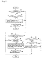
- An example of such control is shown in Fig. 2 , and the routine shown therein is repeated at predetermined short intervals. The routine shown in Fig. 2 is executed upon satisfaction of preconditions to commence the coasting control.
- the preconditions for commencing the coasting control includes: a fact that the vehicle Ve runs at a speed higher than a predetermined speed; a fact that the vehicle Ve runs on a road where a road grade falls within a predetermined range; and a fact that the engine 1 is combusted. That is, the predetermined speed is a reference value of the vehicle speed used to determine to execute the neutral coasting control, and to this end, a threshold value of the vehicle speed is set to a value possible to judge a speed range where the coasting control is effective, based on a simulation result or an experiment.
- the threshold value is set e.g., to 15 to 20 km/h that is a speed of the vehicle Ve creeping on a flat road while idling the engine 1.
- the predetermined range of the road grade is a reference range to determine if the road is a flat road where the gradient is 0%, or if an upgrade or a downgrade will not affect a running load and ignorable.
- such range of the road grade is determined based on a simulation result or an experiment, and may be altered in accordance with the vehicle speed. For example, the range of the road grade is set to ⁇ 2% within the speed range lower than 40km/h, and set to ⁇ 4% within the speed range higher than 40km/h.
- the coasting control is triggered by the fact that the operating amount of the accelerator is reduced to zero or to be smaller than the predetermined amount, in addition to a satisfaction of all of the above-explained preconditions for commencing the coasting control.
- the fact that the operating amount of the accelerator is reduced to zero or to be smaller than a predetermined value is a condition to determine whether or not the accelerator pedal depressed by the driver is released and returned.
- the reference value of the operating amount of the accelerator used to determine to execute the coasting control is not necessarily to be zero.
- the neutral coasting control is commenced when the operating amount of the accelerator is reduced to be smaller than a reference value A.
- the reference value A may be altered in accordance with the engine speed Ne.
- step S2 it is determined whether or not the accelerator is turned “OFF”, that is, whether or not the operating amount of the accelerator is reduced to be smaller than the reference value A.
- step S3 an execution flag of the neutral coasting control is set to "1"
- a current vehicle speed SPD is detected, and the detected vehicle speed SPD is memorized as an initial vehicle speed SPD m at a commencement of the neutral coasting control.
- an interim execution flag of the neutral coasting control is set to "1".
- the execution flag of the neutral coasting control is set to "1" to execute the neutral coasting control, and set to "0" to terminate the neutral coasting control. Accordingly, the execution flag of the neutral coasting control is set to "0" in the beginning of this routine.
- the interim execution flag of the neutral coasting control is used to advance the routine to after-mentioned step S9 to adjust a timing to engage the clutch device 7.
- the interim execution flag of the neutral coasting control is also set to "1" when executing the neutral coasting control.
- the interim execution flag of the neutral coasting control is set to "0" if an increasing amount of the vehicle speed ⁇ SPD exceeds a predetermined value K at after-mentioned steps S6 and S7. Accordingly, the interim execution flag of the neutral coasting control is also set to "0" in the beginning of this routine.
- the clutch device 7 is turned “OFF", in other words, the clutch device 7 is brought into disengagement (at step S4).
- the neutral coasting control of the present invention is executed if the operating amount of the accelerator is reduced to be smaller than the reference value A under the condition where the preconditions of the coasting control are satisfied. Then, the routine is ended.
- step S5 it is determined whether or not the interim execution flag of the neutral coasting control is "1", that is, whether or not the neutral coasting control is being executed.
- step S6 determines whether or not the increasing amount of the vehicle speed ⁇ SPD is greater than the predetermined value K.
- the predetermined value K is a reference value of the increasing amount of the vehicle speed ⁇ SPD to forecast a prospective decelerating demand during execution of the neutral coasting control. To this end, the predetermined value K is preinstalled based on a result of simulation. Thus, when the increasing amount of the vehicle speed ⁇ SPD exceeds the predetermined value K, the decelerating demand of the driver is expected to increase.
- step S6 If the increasing amount of the vehicle speed ⁇ SPD is smaller than the predetermined value K so that the answer of step S6 is NO, the routine is ended without carrying out any specific control. That is, in case the increasing amount of the vehicle speed ⁇ SPD is smaller than the predetermined value K, the decelerating demand of the driver is not expected to increase. In this case, therefore, the controller determines that it is unnecessary to apply a braking force to the vehicle by terminating the neutral coasting control, and continues the neutral coasting control.
- step S7 the routine advances to step S7 to terminate the neutral coasting control and to return to the normal control.
- the speed of the vehicle Ve has been increased to be greater than the predetermined value K during coasting, therefore, the driver may feel uncomfortable feeling or fear if the vehicle speed is further increased.
- the neutral coasting is terminated, and a control to return to the normal control is commenced from step S7 to apply an engine braking force to the vehicle Ve.
- a coasting stage m is determined.
- the coasting stage m is a gear stage established by the automatic transmission 3 during execution of the neutral coasting control, and it can be obtained based on the speed of the vehicle Ve coasting under the neutral coasting control.
- the number of downshifting stages p is number of gear stages of the automatic transmission 3 to be shifted from the current gear stage by a downshifting to terminate the neutral coasting control.
- the number of downshifting stages p is determined based on the increasing amount of the vehicle speed ⁇ SPD calculated at step S6.
- the map shown in Fig. 4 (a) may be preinstalled to determine the number of downshifting stages p.
- a target gear stage g is determined.
- the target gear stage g is a gear stage to be achieved by carrying out the downshifting of the automatic transmission 3 prior to bring the clutch device 7 into engagement to terminate the neutral coasting control.
- target engine speed N etg is calculated.
- N out is a rotational speed of the output shaft 3 of the automatic transmission 3 of the automatic transmission 3
- y g is a speed ratio of the gear stage g
- N eidl is an idling speed of the engine 1.
- the rotational speed N e of the output shaft of the engine 1 is adjusted to the target input speed of the automatic transmission 3 in advance. That is, "N out ⁇ ⁇ g" in the above formula is a term to calculate the input speed N in of the automatic transmission 3.
- the target engine speed N etg is determined in a manner such that the engine speed N e is adjusted to an intermediate value between the input speed N in and the idling speed N eidl .
- the idling speed N eidl is a speed lower than a speed range of the engine 1 under the normal running, and a lowest speed at which the engine 1 free from the load is allowed to rotate autonomously.
- the definition of the "normal running" is a condition where the vehicle Ve is powered by the engine 1 while engaging the clutch device 7.
- an interim execution flag of the neutral coasting control is set to "0", and a timer value T imer is control is reset to "0".
- the timer value T imer is a measurement value of a timer measuring an elapsed time for adjusting timing to engage the clutch device 7.
- a command signal to achieve the target gear stage g determined at the precedent step is sent to the automatic transmission 3, and a command signal to achieve the target engine speed N etg calculated at the precedent step is sent to the engine 1 (at step S8). Consequently, the target gear stage g is established by the automatic transmission 3, and a rotational speed of the engine 1 is adjusted to the target engine speed N etg . Then, the routine is ended.
- step S9 determines whether or not the timer value T imer is equal to or larger than a preset time KT for adjusting the timing to engage the clutch device 7.
- the preset time KT is determined taking account of a response time of the speed change operation of the automatic transmission 3 and a response time of speed control of the engine 1, based on a simulation result or an experiment.
- step S9 If the timer value T imer has not yet reached the preset time KT so that the answer of step S9 is NO, the routine is ended while skipping subsequent steps. That is, the determination of step S9 is repeated until the preset time KT has elapsed from the point at which the determination to terminate the neutral coasting control was made.
- step S10 the routine advances to step S10 to engage the clutch device 7. That is, the neutral coasting control is terminated.
- the clutch device 7 is brought into engagement after the preset time KT has elapsed.
- the speed change operation of the automatic transmission 3, the speed control of the engine 1, and the engaging operation of the clutch device 7 can be executed at appropriate timings while taking account of response delays in the speed change operation of the automatic transmission 3 and the speed control of the engine 1 at step S8. For this reason, the clutch device 7 is allowed to be engaged smoothly and promptly at step S10.
- step S5 After thus bringing the clutch device 7 into engagement to terminate the neutral coasting control, the routine is ended. Specifically, if the answer of step S5 is NO and the routine advances to steps S9 and S10, the execution flag of the neutral coasting control is set to "0" at step S11 and the routine is ended.
- Fig. 5 is a time chart indicating changes in the input speed of the automatic transmission 3 and the speed of the engine 1 under the neutral coasting control of the present invention.
- the preset time KT is started from the point t1 at which a command to increase the engine speed Ne and a command to carry out a downshifting of the automatic transmission 3 are outputted.
- the clutch device 7 is brought into engagement to terminate the neutral coasting control.
- the clutch device 7 is engaged after the preset time KT has elapsed so that the clutch device 7 is allowed to be engaged under the condition where the engine speed N e and the input speed N in are properly raised to the target values. Consequently, the clutch device 7 is allowed to be engaged without causing shocks so that the neutral coasting control can be terminated smoothly.
- the prospective decelerating demand of the driver during execution of the neutral coasting control is determined at step S6.
- Such prospective decelerating demand of the driver during execution of the neutral coasting control may also be estimated by the following procedures.
- the determination of step S6 may be modified to determine whether or not a road grade is a downgrade steeper than a predetermined value. In this case, if the road grade is a downgrade steeper than a predetermined value, the decelerating demand of the driver is expected to increase. By contrast, if the road grade is a downgrade which is not steeper than a predetermined value or an upgrade, the decelerating demand of the driver is not expected to increase.
- the routine is ended while skipping subsequent steps.
- the routine advances to steps S7 and S8 to terminate the neutral coasting control and to carry out the returning control.
- the number of downshifting stages p is determined depending on the downgrade of the road.
- a map shown in Fig. 4 (b) is used to determine the number of downshifting stages p.
- step S6 may be modified to determine whether or not a steering angle of the vehicle Ve is larger than a predetermined angle. In this case, if the steering angle is larger than a predetermined angle, the decelerating demand of the driver is expected to increase. By contrast, if the steering angle is smaller than a predetermined angle, the decelerating demand of the driver is not expected to increase. Accordingly, if the steering angle is smaller than a predetermined angle so that the answer of step S6 is NO, the routine is ended while skipping subsequent steps. To the contrary, if the steering angle is larger than a predetermined angle so that the answer of step S6 is YES, the routine advances to steps S7 and S8 to terminate the neutral coasting control and to carry out the returning control.
- the number of downshifting stages p is determined depending on the steering angle of the vehicle Ve.
- a map shown in Fig. 4 (c) is used to determine the number of downshifting stages p.
- step S6 may be modified to determine whether or not an acceleration of the vehicle Ve is greater than a predetermined value.
- a longitudinal acceleration and a lateral acceleration of the vehicle Ve is detected to be determined if it is greater than the predetermined value or not.
- the detected lateral acceleration is greater than the predetermined value, the decelerating demand of the driver is expected to increase.
- the detected lateral acceleration is less than the predetermined value, the decelerating demand of the driver is not expected to increase.
- the routine is ended while skipping subsequent steps.
- the routine advances to steps S7 and S8 to terminate the neutral coasting control and to carry out the returning control.
- the number of downshifting stages p is determined depending on the acceleration of the vehicle Ve.
- a map shown in Fig. 4 (d) is used to determine the number of downshifting stages p.
- the control system of the present invention reduces to speed of the engine 1 to the idling speed while disengaging the clutch device 7 to interrupt power transmission between the engine 1 and the drive wheels 2. That is, the neutral coasting control is executed to allow the vehicle to coast. Consequently, a possible coasting distance of the vehicle Ve under the condition in which the engine 1 is free from the load can be extended so that the fuel economy of the vehicle Ve can be improved.
- the prospective decelerating demand of the driver is estimated based on a change in the vehicle speed, an acceleration, a change in a road grade etc. during execution of the coasting control. If the controller determines that the decelerating demand of the driver will be increased, the clutch device 7 is brought into engagement to terminate the coasting control, and downshifting is carried out to increase a speed ratio of the automatic transmission 3. Thus, if the decelerating demand is expected to increase, the coasting control is terminated to apply an engine braking force to the vehicle Ve. In this situation, a braking force is also applied to the vehicle by carrying out downshifting.
- a speed or an acceleration of the vehicle Ve can be reduced or suppressed in line with the decelerating or braking demand of the driver during execution of the coasting control. For this reason, the coasting control can be carried out properly without diminishing drivability of the vehicle.
- the coasting control can be executed and terminated taking account of the effect of the vehicle speed. Specifically, the coasting control is executed if the vehicle speed falls within the speed range higher than the predetermined speed where the coasting control is effective, and the coasting control is terminated or inhibited if the vehicle speed is lower than the predetermined speed where the coasting control is not effective. Thus, the coasting control can be executed and terminated properly depending on the situation.
- the control system of the invention executes the coasting control taking account of an operating condition of the engine 1 and the engine speed N e .
- the coasting control is carried out under the condition where the engine 1 is combusted, and the engine speed N e is lowered to the idling speed N eidle during execution of the coasting control. For this reason, the coasting control can be executed effectively to improve fuel economy of the vehicle Ve.
- the functional means to carry out the controls of steps S1 and S2 serve as the "means that detects an operation of an accelerator" of the invention
- the functional means to carry out the control of step S4 serves as the "execution means” of the invention
- the functional means to carry out the control of step S6 serves as the "estimation means” of the invention
- the functional means to carry out the controls of steps S7, S8, S9 and S10 serve as the "returning means" of the invention.
Abstract
Description
- The present invention relates to a control system for a vehicle that is provided with a clutch device for selectively connect and disconnect a prime mover to/from drive wheels through a power transmission route, and that is allowed to coast by bringing the clutch device into disengagement.
- In order to improve fuel economy, a fuel cut-off control for stopping fuel supply to an engine during running, and a coasting control for coasting the vehicle by disconnecting the engine from a drive line during running have been employed in recent years. Specifically, the fuel cut-off is carried out to stop fuel supply to the engine given that an accelerator is returned to close an accelerator valve completely, and that an engine speed is higher than an idling speed so that a vehicle speed is higher than a predetermined speed. Under the fuel cut-off control, although the combustion of fuel in the engine is stopped, the engine is still rotating by a torque from the drive wheels. Therefore, a braking torque resulting from a pumping loss of the engine and a friction torque is applied to the drive wheels. Consequently, an engine braking force is applied to the vehicle.
- For example, the coasting control is carried out when the accelerator is returned during running to coast the vehicle without rotating the engine passively by bringing the clutch into disengagement disposed between the engine and the drive wheels. Therefore, under the coasting control, the engine braking force will not be applied to the vehicle so that the vehicle is allowed to coast utilizing an inertia energy.
- The coasting control may be carried out not only by stopping the fuel supply to the engine but also without stopping the fuel supply to the engine while lowering the engine speed close to the idling speed. In case of carrying out the coasting control while stopping the engine, the fuel will not be consumed during coasting the vehicle so that the fuel economy can be improved significantly By contrast, in case of carrying out the coasting control without stopping the engine, the fuel economy will not be improved as the case of stopping the engine. In this case, however, it is not necessary to arrange additional devices for insuring a required oil pressure under cessation of the engine such as an electric oil pump, a hydraulic accumulator etc. Therefore, the coasting control can be carried out easily without requiring additional modification of the vehicle and additional equipment. In the following explanation, the coasting control without stopping the engine will be called the "neutral coasting control" or the "N coasting control".
- For example, Japanese Patent Laid-Open No.
2011-163535 2011-163535 - Japanese Patent Laid-Open No.
2010-60010 2010-60010 - Japanese Patent Laid-Open No.
2008-106841 2008-106841 2008-106841 - As described, according to the teachings of Japanese Patent Laid-Open No.
2011-163535 - The present invention has been conceived noting the foregoing technical problem, and it is therefore an object of the present invention is to provide a vehicle control system for carrying out the coasting control of a vehicle by interrupting a power transmission between a prime mover and drive wheels, without diminishing drivability of the vehicle.
- The vehicle control system of the present invention is applied to a vehicle having a clutch device adapted to selectively connect and disconnect a power transmission route between a prime mover and drive wheels, and that is configured to disconnect the power transmission route during running to allow the vehicle to coast. In order to achieve the above-mentioned objective, the vehicle control system is provided with: a means that detects a vehicle speed; a means that detects an operation of an accelerator by a driver; an execution means that executes a coasting control when an operating amount of an accelerator is reduced to be smaller than a predetermined value during running, by bringing the clutch device into disengagement to disconnect the power transmission route so as to allow the vehicle to coast; an estimation means that estimates a decelerating demand of the driver during execution of the coasting control; and a returning means that terminates the coasting control by bringing the clutch device into engagement to connect the power transmission route, and that increases a speed ratio of the automatic transmission when the decelerating demand is expected to increase.
- The estimation means may be configured to determine a fact that the decelerating demand increases if an increasing amount of the vehicle speed is larger than a predetermined value.
- The vehicle control system is further provided with a means that detects an acceleration of the vehicle. In addition, the estimation means may also be configured to determine a fact that the decelerating demand increases if at least any of a longitudinal acceleration and a lateral acceleration of the vehicle is greater than a predetermined value.
- The vehicle control system is further provided with a means that detects a road gradient. In addition, the estimation means may also be configured to determine a fact that the decelerating demand increases if the road gradient is steeper than a predetermined downgrade.
- The vehicle control system is further provided with a means that detects a steering angle of the vehicle. In addition, the estimation means may also be configured to determine a fact that the decelerating demand increases if the steering angle is larger than a predetermined angle.
- The vehicle control system is further provided with a means that detects an output speed of an output shaft of the prime mover. In addition, the returning means may also be configured to adjust the output speed of the prime mover to a target input speed of the automatic transmission of a case in which the speed ratio is increased, when the clutch device is brought into engagement.
- The execution means may also be configured to execute the coasting control if the operating amount of the accelerator is reduced to be smaller than the predetermined value during running, and the vehicle runs at a speed higher than a predetermined speed. In addition, the returning means may also be configured to terminate the coasting control when the vehicle speed is reduced to be lower than the predetermined speed.
- An engine for generating power by burning fuel may be used as the prime mover, and the vehicle control system is further provided with an engine speed detection means. The execution means may also be configured to execute the coasting control if the operating amount of the accelerator is reduced to be smaller than the predetermined value during running and the engine is combusted, and to control the engine during execution of the coasting control in a manner such that the engine speed is reduced to an idling speed that is lower than that of the case in which the vehicle runs without carrying out the coasting control.
- Thus, according to the present invention, the clutch device is brought into disengagement to disconnect the power transmission route between the prime mover and the drive wheels. That is, the coasting control is executed to allow the vehicle to coast. Consequently, a cruising distance of the vehicle can be extended without applying a load to the prime mover so that the energy efficiency of the vehicle can be improved.
- As described, the control system of the present invention estimates the prospective decelerating demand of the driver based on a change in the vehicle speed an acceleration, a change in a road gradient during execution of the coasting control. If the decelerating demand is expected to increase, the clutch device is brought into engagement to terminate the coasting control, and the speed ratio of the automatic transmission is increased to be larger than the current speed ratio. That is, a downshifting is carried out. Thus, if the decelerating demand is expected to increase, the coasting control is terminated to apply a braking torque derived from a load and a resistance of the power transmission route is applied to the drive wheels. In addition, a braking force resulting from the downshifting of the automatic transmission is also applied to the vehicle. Therefore, the vehicle can be decelerated in line with the decelerating or braking demand of the driver during execution of the coasting control. For this reason, the coasting control can be carried out properly without diminishing drivability of the vehicle.
- As also described, the control system of the present invention estimates the prospective decelerating demand based on an increasing amount of the vehicle speed, an acceleration of the vehicle, a road grade, or a steering angle. Specifically, if the increasing amount of the vehicle speed exceeds the predetermined value, if the longitudinal or lateral acceleration exceeds the predetermined value, if the road grade is steeper than the predetermined downgrade, or if the steering angle of the vehicle exceeds he predetermined value, the decelerating demand is expected to increase. Therefore, the decelerating demand of the driver can be estimated accurately during execution of the coasting control so that the coasting control can be carried out properly.
- According to the present invention, the coasting control may also be executed and terminated taking account of the vehicle speed. For example, the coasting control is allowed to be carried out if the vehicle speed is higher than a predetermined speed where the coasting control is effective, and the coasting control is inhibited if the vehicle speed is lower than a predetermined speed where the coasting control is not effective. Thus, the coasting control can be appropriately executed and terminated depending on a situation.
- In addition, given that the control system pf the present invention is applied to a vehicle in which the engine is used as the prime mover, the coasting control can be carried out taking account of an operating condition of the engine such as an engine speed. That is, the coasting control can be carried out while combusting the engine, and in this case, the engine speed is kept to the idling speed during the execution of the coasting control. Therefore, the coasting control can be carried out effectively to improve fuel economy.
-
-
Fig. 1 is a view schematically showing an example of a drive line and a control line of the vehicle to which the control system of the present invention is applied. -
Fig. 2 is a flowchart showing one example of the coasting control carried out by the control system of the present invention. -
Fig. 3 shows one example of a map used in the coasting control according to the present invention. -
Fig. 4 shows one example of a map used in the coasting control according to the present invention. -
Fig. 5 is a time chart showing behaviors of the prime mover and the automatic transmission during execution of the coasting control of the present invention. - Next, the present invention will be explained in more detail with reference to the accompanying drawings.
Fig. 1 shows a drive line and a control line of the vehicle to which the control system of the present invention is applied. As shown inFig. 1 , the vehicle Ve is comprised of anengine 1, and anautomatic transmission 3 connected to an output side of theengine 1 to transmit a power of theengine 1 to drivewheels 2. Specifically, theautomatic transmission 3 is disposed on the output side of theengine 1, and anoutput shaft 3a of theautomatic transmission 3 is connected to thedrive wheels 2 to transmit power therebetween through a propeller shaft 4, adifferential gear 5 and adrive shaft 6. Thus,Fig. 1 shows an example of rear-drive layout of the vehicle Ve in which theengine 1 is connected to therear drive wheels 2 through the propeller shaft 4. However, the control system of the present invention may also be applied to a front drive vehicle and a four-wheel drive vehicle. - The
engine 1 serves as a prime mover of the present invention, and for example, an internal combustion engine for generating a power by burning fuel such as a gasoline engine, a diesel engine a natural gas engine and etc. may be used. According to the example shown inFig. 1 , the gasoline engine is used as theengine 1, and theengine 1 is comprised of an electronic throttle valve an opening degree thereof is controlled electrically, and a fuel injector an injecting amount thereof is controlled electrically. Therefore, theengine 1 can be operated in an optimally fuel efficient manner by electrically controlling a rotational speed with respect to a predetermined load. - The
automatic transmission 3 is adapted to transmit a torque of theengine 1 to thedrive wheels 2 while carrying out a speed change. For example, a geared automatic transmission (AT), a belt-driven or toroidal continuously variable transmission (CVT), a dual-clutch automatic transmission (DCT) based on a geared manual transmission, an automatic clutch manual transmission (AMT) and so on may be used as theautomatic transmission 3. The vehicle Ve is further provided with aclutch device 7 adapted to selectively allow a power transmission between theengine 1 and thedrive wheels 2, irrespective of a type of theautomatic transmission 3, and irrespective of a drive system such as a front drive system, a rear drive system and a four wheel drive system. - According to the example shown in
Fig. 1 , a geared automatic transmission having a planetary gear unit is employed as theautomatic transmission 3. As the conventional AT, theautomatic transmission 3 is comprised of a plurality of planetary gear units (not shown), a forward clutch 7a engaged to establish a forward stage, and areverse brake 7b engaged to establish a reverse stage. Optionally, theautomatic transmission 3 may be provided with an additional clutch or brake to be engaged to establish a predetermined forward stage. Accordingly, theautomatic transmission 3 is brought into a neutral stage by disengaging both of the forward clutch 7a and thereverse brake 7b. As a result of thus disengaging the forward clutch 7a and thereverse brake 7b, theengine 1 is disconnected from thedrive wheels 2 so that the power transmission therebetween is interrupted. Accordingly, in the example shown inFig. 1 , theclutch device 7 comprised of the forward clutch 7a and thereverse brake 7b serves as the clutch device of the invention. - As described, the CVT may be used as the
automatic transmission 3. The conventional CVT is comprised of a belt driven transmission and a torque reversing device for reversing a direction of the torque transmitted to thedrive wheels 2 between the forward direction and the backward direction. Specifically, the torque reversing device is comprised of a forward clutch engaged to establish the forward stage and a reverse clutch engaged to establish the reverse stage. Therefore, the power transmission between theengine 1 and theautomatic transmission 3 is interrupted by disengaging both of the forward clutch and the reverse brake. That is, a neutral stage of theautomatic transmission 3 is established. In this case, the forward clutch and the reverse brake serve as the clutch device of the invention. - Given that the DCT is used as the
automatic transmission 3, the power transmission between theengine 1 and theautomatic transmission 3 is interrupted by disengaging both of the clutches of the DCT. That is, a neutral stage of theautomatic transmission 3 is established. In this case, the two clutches of the DCT serve as the clutch device of the invention. - Given that the AMT is used as the
automatic transmission 3, the power transmission between theengine 1 and theautomatic transmission 3 is interrupted by disengaging a clutch of the conventional manual transmission device and theengine 1. That is, a neutral stage of theautomatic transmission 3 is established. In this case, the above-explained clutch serves as the clutch device of the invention. - The control system of the present invention may be applied not only to a hybrid vehicle in which the prime mover is comprised of an internal combustion engine and an electric motor, but also to an electric vehicle in which only the electric motor is used as the prime mover. In order to selectively connect and disconnect the power transmission route between the prime mover and the
drive wheels 2, according to the present invention, the vehicle Ve is provided with theclutch device 7 irrespective of a kind of the prime mover such as theengine 1, the electric motor, and a hybrid drive unit comprised of theengine 1 and the electric motor. For example, a friction clutch and a dog clutch may be used as theclutch device 7, and in case of using the friction clutch, any of a wet type and a dry type friction clutches may be used. That is, any kinds of clutch devices may be used as theclutch device 7 to selectively allow and interrupt a power transmission route between the prime mover such as theengine 1, the electric motor, and a hybrid drive unit and thedrive wheels 2 to transmit power therebetween. - Given that the vehicle Ve is the hybrid vehicle or the electric vehicle having the electric motor as the prime mover, a braking force can be applied to the vehicle Ve by carrying out a regeneration control of the electric motor while engaging the
clutch device 7. Specifically, a braking torque can be applied to thedrive wheels 2 to decelerate the vehicle Ve during running by operating the electric motor as a generator while engaging theclutch device 7. - In order to control an operating condition of the
engine 1 and engagement state of theclutch device 7, the vehicle Ve is provided with an electronic control unit (ECU) 8 as a controller that is configured to carry out a calculation based on input data and preinstalled data, and to output a calculation result in the form of a command signal. For example, detection signals from awheel speed sensor 9 adapted to detect a rotational speed of each wheel of the vehicle Ve, anaccelerator sensor 10 adapted to detect a depressing angle or a depressing amount of an accelerator pedal, anengine speed sensor 11 adapted to detect a speed of the output shaft of theengine 1, alongitudinal acceleration sensor 12 adapted to detect a longitudinal acceleration of the vehicle Ve, alateral acceleration sensor 13 adapted to detect a lateral acceleration of the vehicle Ve, aninclination sensor 14 adapted to detect an inclination angle of the vehicle Ve and so on are sent to theelectronic control unit 8. Based on those signals, theelectronic control unit 8 sends a command signals to theengine 1 to control the operating condition, and to theclutch device 7 to control the engagement state. - Given that the electric motor is used as the prime mover of the vehicle Ve, a detection signal from a speed sensor for the electric motor or a resolver is additionally sent to the
electronic control unit 8. In this case, theelectronic control unit 8 sends a command signal to the electric motor to control the operating condition. - In order to improve fuel economy of the vehicle Ve thus structured, the control system of the present invention carries out the coasting control of the vehicle Ve by bringing the
clutch device 7 into disengagement during running. According to the present invention, specifically, the coasting control is carried out to cutoff a power transmission route between theengine 1 and thedrive wheel 2 by disengaging theclutch device 7, under a condition that the accelerator pedal is not depressed, in other words, completely returned while the vehicle Ve is moving at a speed higher than a predetermined speed. Under the coasting control, however, theengine 1 will not be stopped. That is, under the coasting control, although the speed of theengine 1 is lowered almost to an idling speed, the fuel combustion is carried on. - Thus, under the coasting control, a power transmission between the
engine 1 and thedrive wheel 2 is interrupted. Therefore, a braking torque resulting from a pumping loss of theengine 1 and a drag torque will not be applied to thedrive wheels 2 of the vehicle Ve. In other words, an engine braking force will not be applied to the vehicle Ve. Therefore, under the coasting control, a possible coasting distance achieved by an inertia energy of the vehicle Ve is extended. Consequently, a cruising distance of the vehicle Ve per unit of fuel can be extended so that the fuel economy of the vehicle Ve can be improved. - Under the coasting control, the fuel economy of the vehicle Ve can be further improved if the fuel combustion of the
engine 1 is stopped while disengaging theclutch device 7. However, if the fuel combustion of theengine 1 is stopped, a power for actuating auxiliaries such as an oil pump and a compressor for an air conditioner, and a power for actuating a hydraulic power steering system and a brake system will be lost. In this case, therefore, a substitute power source (e.g., an electric motor) and a hydraulic accumulator are required for the case of cessation of theengine 1. By contrast, given that theengine 1 is not stopped under the coasting control, the power for driving those auxiliaries and the power steering and the brake systems will not be lost. In this case, therefore, the coasting control can be carried out easily in the conventional vehicles without requiring the additional power source. - The control system of the present invention is configured to carry out the coasting control without diminishing drivability of the vehicle Ve by continuing or terminating the coasting control properly even if a speed of the vehicle Ve is changed by a change in a road grade during execution of the coasting control. An example of such control is shown in
Fig. 2 , and the routine shown therein is repeated at predetermined short intervals. The routine shown inFig. 2 is executed upon satisfaction of preconditions to commence the coasting control. - The preconditions for commencing the coasting control includes: a fact that the vehicle Ve runs at a speed higher than a predetermined speed; a fact that the vehicle Ve runs on a road where a road grade falls within a predetermined range; and a fact that the
engine 1 is combusted. That is, the predetermined speed is a reference value of the vehicle speed used to determine to execute the neutral coasting control, and to this end, a threshold value of the vehicle speed is set to a value possible to judge a speed range where the coasting control is effective, based on a simulation result or an experiment. Specifically, given that the vehicle Ve has a torque converter, the threshold value is set e.g., to 15 to 20 km/h that is a speed of the vehicle Ve creeping on a flat road while idling theengine 1. In turn, the predetermined range of the road grade is a reference range to determine if the road is a flat road where the gradient is 0%, or if an upgrade or a downgrade will not affect a running load and ignorable. To this end, such range of the road grade is determined based on a simulation result or an experiment, and may be altered in accordance with the vehicle speed. For example, the range of the road grade is set to ± 2% within the speed range lower than 40km/h, and set to ±4% within the speed range higher than 40km/h. - According to the control example shown in
Fig. 2 , first of all, it is determined whether or not the accelerator was "ON" during the previous routine. Specifically, it is determined whether or not an operating amount of the accelerator was not zero or smaller than a predetermined operating amount (at step S1). According to the present invention, the coasting control is triggered by the fact that the operating amount of the accelerator is reduced to zero or to be smaller than the predetermined amount, in addition to a satisfaction of all of the above-explained preconditions for commencing the coasting control. Specifically, the fact that the operating amount of the accelerator is reduced to zero or to be smaller than a predetermined value is a condition to determine whether or not the accelerator pedal depressed by the driver is released and returned. The reference value of the operating amount of the accelerator used to determine to execute the coasting control is not necessarily to be zero. For example, as indicated in the map shown inFig. 3 , the neutral coasting control is commenced when the operating amount of the accelerator is reduced to be smaller than a reference value A. Optionally, as shown inFig. 3 , the reference value A may be altered in accordance with the engine speed Ne. - If the accelerator was "ON", that is, if the operating amount of the accelerator was not smaller than the reference value A in the beginning of the routine and during the previous routine so that the answer of step S1 is YES, the routine advances to step S2. At step S2, it is determined whether or not the accelerator is turned "OFF", that is, whether or not the operating amount of the accelerator is reduced to be smaller than the reference value A.
- If the accelerator has not yet been turned "OFF", that is, if the operating amount of the accelerator has not yet reduced to be smaller than the reference value A so that the answer of step S2 is NO, the routine is ended without carrying out any specific control. By contrast, if the accelerator has already been turned "OFF", that is, if the operating amount of the accelerator has already been reduced to be smaller than the reference value A so that the answer of step S2 is YES, the routine advances to step S3. At step S3, an execution flag of the neutral coasting control is set to "1", a current vehicle speed SPD is detected, and the detected vehicle speed SPD is memorized as an initial vehicle speed SPDm at a commencement of the neutral coasting control. In addition, an interim execution flag of the neutral coasting control is set to "1".
- Specifically, the execution flag of the neutral coasting control is set to "1" to execute the neutral coasting control, and set to "0" to terminate the neutral coasting control. Accordingly, the execution flag of the neutral coasting control is set to "0" in the beginning of this routine. On the other hand, the interim execution flag of the neutral coasting control is used to advance the routine to after-mentioned step S9 to adjust a timing to engage the
clutch device 7. To this end, the interim execution flag of the neutral coasting control is also set to "1" when executing the neutral coasting control. By contrast, the interim execution flag of the neutral coasting control is set to "0" if an increasing amount of the vehicle speed ΔSPD exceeds a predetermined value K at after-mentioned steps S6 and S7. Accordingly, the interim execution flag of the neutral coasting control is also set to "0" in the beginning of this routine. - Then, the
clutch device 7 is turned "OFF", in other words, theclutch device 7 is brought into disengagement (at step S4). Thus, the neutral coasting control of the present invention is executed if the operating amount of the accelerator is reduced to be smaller than the reference value A under the condition where the preconditions of the coasting control are satisfied. Then, the routine is ended. - If the accelerator was "OFF", that is, if the operating amount of the accelerator was smaller than the reference value A during the previous routine so that the answer of step S1 is NO, the routine advances to step S5. At step S5, it is determined whether or not the interim execution flag of the neutral coasting control is "1", that is, whether or not the neutral coasting control is being executed.
- If the interim execution flag of the neutral coasting control is "1", that is, if the neutral coasting control has already been commenced so that the answer of step S5 is YES, the routine advances to step S6 to determine whether or not the increasing amount of the vehicle speed ΔSPD is greater than the predetermined value K. Specifically, the increasing amount of the vehicle speed ΔSPD is a deviation between the current vehicle speed SPD and the initial vehicle speed SPDm, and the increasing amount of the vehicle speed ΔSPD can be calculated by the following formula:

- The predetermined value K is a reference value of the increasing amount of the vehicle speed ΔSPD to forecast a prospective decelerating demand during execution of the neutral coasting control. To this end, the predetermined value K is preinstalled based on a result of simulation. Thus, when the increasing amount of the vehicle speed ΔSPD exceeds the predetermined value K, the decelerating demand of the driver is expected to increase.
- If the increasing amount of the vehicle speed ΔSPD is smaller than the predetermined value K so that the answer of step S6 is NO, the routine is ended without carrying out any specific control. That is, in case the increasing amount of the vehicle speed ΔSPD is smaller than the predetermined value K, the decelerating demand of the driver is not expected to increase. In this case, therefore, the controller determines that it is unnecessary to apply a braking force to the vehicle by terminating the neutral coasting control, and continues the neutral coasting control.
- By contrast, if the increasing amount of the vehicle speed ΔSPD is larger than the predetermined value K so that the answer of step S6 is YES, the routine advances to step S7 to terminate the neutral coasting control and to return to the normal control. In this case, the speed of the vehicle Ve has been increased to be greater than the predetermined value K during coasting, therefore, the driver may feel uncomfortable feeling or fear if the vehicle speed is further increased. In order to reduce or suppress further increment of the vehicle speed thus reached to the predetermined value K, the neutral coasting is terminated, and a control to return to the normal control is commenced from step S7 to apply an engine braking force to the vehicle Ve.
- At step S7, first of all, a coasting stage m is determined. Specifically, the coasting stage m is a gear stage established by the
automatic transmission 3 during execution of the neutral coasting control, and it can be obtained based on the speed of the vehicle Ve coasting under the neutral coasting control. - Then, number of downshifting stages p is determined.
- Specifically, the number of downshifting stages p is number of gear stages of the
automatic transmission 3 to be shifted from the current gear stage by a downshifting to terminate the neutral coasting control. To this end, the number of downshifting stages p is determined based on the increasing amount of the vehicle speed ΔSPD calculated at step S6. For example, the map shown inFig. 4 (a) may be preinstalled to determine the number of downshifting stages p. - Thereafter, a target gear stage g is determined. Specifically, the target gear stage g is a gear stage to be achieved by carrying out the downshifting of the
automatic transmission 3 prior to bring theclutch device 7 into engagement to terminate the neutral coasting control. The target gear stage g can be calculated based on the coasting stage m and the number of downshifting stages p, as expressed by the following expression:
- Further, a target engine speed Netg is calculated. Specifically, target engine speed Netg can be calculated by the following formula:

where Nout is a rotational speed of theoutput shaft 3 of theautomatic transmission 3, y g is a speed ratio of the gear stage g, and Neidl is an idling speed of theengine 1. In order to engage the clutch device smoothly at after-mentioned step S10, the rotational speed Ne of the output shaft of theengine 1 is adjusted to the target input speed of theautomatic transmission 3 in advance. That is, "Nout · γ g" in the above formula is a term to calculate the input speed Nin of theautomatic transmission 3. To this end, the target engine speed Netg is determined in a manner such that the engine speed Ne is adjusted to an intermediate value between the input speed Nin and the idling speed Neidl. Specifically, the idling speed Neidl is a speed lower than a speed range of theengine 1 under the normal running, and a lowest speed at which theengine 1 free from the load is allowed to rotate autonomously. Here, the definition of the "normal running" is a condition where the vehicle Ve is powered by theengine 1 while engaging theclutch device 7. - In addition, an interim execution flag of the neutral coasting control is set to "0", and a timer value Timer is control is reset to "0". The timer value Timer is a measurement value of a timer measuring an elapsed time for adjusting timing to engage the
clutch device 7. - Then, a command signal to achieve the target gear stage g determined at the precedent step is sent to the
automatic transmission 3, and a command signal to achieve the target engine speed Netg calculated at the precedent step is sent to the engine 1 (at step S8). Consequently, the target gear stage g is established by theautomatic transmission 3, and a rotational speed of theengine 1 is adjusted to the target engine speed Netg. Then, the routine is ended. - By contrast, if the interim execution flag of the neutral coasting control is not "1", that is, if the interim execution flag of the neutral coasting control is set to "0" at step S7 so that the answer of step S5 is NO, the routine advances to step S9 to determine whether or not the timer value Timer is equal to or larger than a preset time KT for adjusting the timing to engage the
clutch device 7. For example, the preset time KT is determined taking account of a response time of the speed change operation of theautomatic transmission 3 and a response time of speed control of theengine 1, based on a simulation result or an experiment. - If the timer value Timer has not yet reached the preset time KT so that the answer of step S9 is NO, the routine is ended while skipping subsequent steps. That is, the determination of step S9 is repeated until the preset time KT has elapsed from the point at which the determination to terminate the neutral coasting control was made.
- By contrast, if the timer value Timer has reached the preset time KT so that the answer of step S9 is YES, the routine advances to step S10 to engage the
clutch device 7. That is, the neutral coasting control is terminated. Thus, theclutch device 7 is brought into engagement after the preset time KT has elapsed. As a result, the speed change operation of theautomatic transmission 3, the speed control of theengine 1, and the engaging operation of theclutch device 7 can be executed at appropriate timings while taking account of response delays in the speed change operation of theautomatic transmission 3 and the speed control of theengine 1 at step S8. For this reason, theclutch device 7 is allowed to be engaged smoothly and promptly at step S10. - After thus bringing the
clutch device 7 into engagement to terminate the neutral coasting control, the routine is ended. Specifically, if the answer of step S5 is NO and the routine advances to steps S9 and S10, the execution flag of the neutral coasting control is set to "0" at step S11 and the routine is ended. -
Fig. 5 is a time chart indicating changes in the input speed of theautomatic transmission 3 and the speed of theengine 1 under the neutral coasting control of the present invention. When the increasing amount of the vehicle speed ΔSPD during execution of the neutral coasting control exceeds the predetermined value K at point t1, the returning control to the normal control is commenced. Specifically, the engine speed Ne is increased from the idling speed Neidl to the target engine speed Netg, and a downshifting is carried out to shift the gear stage of theautomatic transmission 3 to the target stage g. Consequently, the input speed Nin of theautomatic transmission 3 is increased. In this situation, the engine speed Ne and the input speed Nin are inevitably delayed to be increased to the target engine speed Netg and the speed to be achieved under the target stage g. In order to prevent such response delay, the preset time KT is started from the point t1 at which a command to increase the engine speed Ne and a command to carry out a downshifting of theautomatic transmission 3 are outputted. - Then, when the preset time KT has elapsed at point t2, the
clutch device 7 is brought into engagement to terminate the neutral coasting control. Thus, theclutch device 7 is engaged after the preset time KT has elapsed so that theclutch device 7 is allowed to be engaged under the condition where the engine speed Ne and the input speed Nin are properly raised to the target values. Consequently, theclutch device 7 is allowed to be engaged without causing shocks so that the neutral coasting control can be terminated smoothly. - As described, according to the control example shown in
Fig. 2 , the prospective decelerating demand of the driver during execution of the neutral coasting control is determined at step S6. Such prospective decelerating demand of the driver during execution of the neutral coasting control may also be estimated by the following procedures. For example, the determination of step S6 may be modified to determine whether or not a road grade is a downgrade steeper than a predetermined value. In this case, if the road grade is a downgrade steeper than a predetermined value, the decelerating demand of the driver is expected to increase. By contrast, if the road grade is a downgrade which is not steeper than a predetermined value or an upgrade, the decelerating demand of the driver is not expected to increase. Accordingly, if the road grade is a downgrade which is not steeper than a predetermined value or an upgrade so that the answer of step S6 is NO, the routine is ended while skipping subsequent steps. To the contrary, if the road grade is a downgrade steeper than a predetermined value so that the answer of step S6 is YES, the routine advances to steps S7 and S8 to terminate the neutral coasting control and to carry out the returning control. - In this case, the number of downshifting stages p is determined depending on the downgrade of the road. To this end, a map shown in
Fig. 4 (b) is used to determine the number of downshifting stages p. - Instead, the determination of step S6 may be modified to determine whether or not a steering angle of the vehicle Ve is larger than a predetermined angle. In this case, if the steering angle is larger than a predetermined angle, the decelerating demand of the driver is expected to increase. By contrast, if the steering angle is smaller than a predetermined angle, the decelerating demand of the driver is not expected to increase. Accordingly, if the steering angle is smaller than a predetermined angle so that the answer of step S6 is NO, the routine is ended while skipping subsequent steps. To the contrary, if the steering angle is larger than a predetermined angle so that the answer of step S6 is YES, the routine advances to steps S7 and S8 to terminate the neutral coasting control and to carry out the returning control.
- In this case, the number of downshifting stages p is determined depending on the steering angle of the vehicle Ve. To this end, a map shown in
Fig. 4 (c) is used to determine the number of downshifting stages p. - In addition, the determination of step S6 may be modified to determine whether or not an acceleration of the vehicle Ve is greater than a predetermined value. For this purpose, at least any of a longitudinal acceleration and a lateral acceleration of the vehicle Ve is detected to be determined if it is greater than the predetermined value or not. For example, if the detected lateral acceleration is greater than the predetermined value, the decelerating demand of the driver is expected to increase. By contrast, if the detected lateral acceleration is less than the predetermined value, the decelerating demand of the driver is not expected to increase. Accordingly, if the acceleration of the vehicle Ve is less than the predetermined value so that the answer of step S6 is NO, the routine is ended while skipping subsequent steps. To the contrary, if the acceleration of the vehicle Ve is greater than the predetermined value so that the answer of step S6 is YES, the routine advances to steps S7 and S8 to terminate the neutral coasting control and to carry out the returning control.
- In this case, the number of downshifting stages p is determined depending on the acceleration of the vehicle Ve. To this end, a map shown in
Fig. 4 (d) is used to determine the number of downshifting stages p. - Thus, if the operating amount of the accelerator is reduced to zero during running of the vehicle Ve, the control system of the present invention reduces to speed of the
engine 1 to the idling speed while disengaging theclutch device 7 to interrupt power transmission between theengine 1 and thedrive wheels 2. That is, the neutral coasting control is executed to allow the vehicle to coast. Consequently, a possible coasting distance of the vehicle Ve under the condition in which theengine 1 is free from the load can be extended so that the fuel economy of the vehicle Ve can be improved. - During execution of the coasting control, the prospective decelerating demand of the driver is estimated based on a change in the vehicle speed, an acceleration, a change in a road grade etc. during execution of the coasting control. If the controller determines that the decelerating demand of the driver will be increased, the
clutch device 7 is brought into engagement to terminate the coasting control, and downshifting is carried out to increase a speed ratio of theautomatic transmission 3. Thus, if the decelerating demand is expected to increase, the coasting control is terminated to apply an engine braking force to the vehicle Ve. In this situation, a braking force is also applied to the vehicle by carrying out downshifting. Therefore, a speed or an acceleration of the vehicle Ve can be reduced or suppressed in line with the decelerating or braking demand of the driver during execution of the coasting control. For this reason, the coasting control can be carried out properly without diminishing drivability of the vehicle. - In addition, according to the present invention, the coasting control can be executed and terminated taking account of the effect of the vehicle speed. Specifically, the coasting control is executed if the vehicle speed falls within the speed range higher than the predetermined speed where the coasting control is effective, and the coasting control is terminated or inhibited if the vehicle speed is lower than the predetermined speed where the coasting control is not effective. Thus, the coasting control can be executed and terminated properly depending on the situation.
- Given that the internal combustion engine is used in the vehicle Ve, the control system of the invention executes the coasting control taking account of an operating condition of the
engine 1 and the engine speed Ne. Specifically, the coasting control is carried out under the condition where theengine 1 is combusted, and the engine speed Ne is lowered to the idling speed Neidle during execution of the coasting control. For this reason, the coasting control can be executed effectively to improve fuel economy of the vehicle Ve. - Here will be briefly explained a relation between the above-explained example and the present invention. The functional means to carry out the controls of steps S1 and S2 serve as the "means that detects an operation of an accelerator" of the invention, the functional means to carry out the control of step S4 serves as the "execution means" of the invention, the functional means to carry out the control of step S6 serves as the "estimation means" of the invention, and the functional means to carry out the controls of steps S7, S8, S9 and S10 serve as the "returning means" of the invention.
Claims (8)
- A vehicle control system, that is applied to a vehicle having a clutch device adapted to selectively connect and disconnect a power transmission route between a prime mover and drive wheels, and that is configured to disconnect the power transmission route during running to allow the vehicle to coast,
characterized by:a means that detects a vehicle speed;a means that detects an operation of an accelerator by a driver;an execution means that executes a coasting control when an operating amount of an accelerator is reduced to be smaller than a predetermined value during running, by bringing the clutch device into disengagement to disconnect the power transmission route so as to allow the vehicle to coast;an estimation means that estimates a decelerating demand of the driver during execution of the coasting control; anda returning means that terminates the coasting control by bringing the clutch device into engagement to connect the power transmission route, and that increases a speed ratio of the automatic transmission when the decelerating demand is expected to increase. - The vehicle control system as claimed in claim 1,
wherein the estimation means includes a means that determines a fact that the decelerating demand increases if an increasing amount of the vehicle speed is larger than a predetermined value. - The vehicle control system as claimed in claim 1, further comprising:a means that detects an acceleration of the vehicle; andwherein the estimation means includes a means that determines a fact that the decelerating demand increases if at least any of a longitudinal acceleration and a lateral acceleration of the vehicle is greater than a predetermined value.
- The vehicle control system as claimed in claim 1, further comprising:a means that detects a road gradient; andwherein the estimation means includes a means that determines a fact that the decelerating demand increases if the road gradient is steeper than a predetermined downgrade.
- The vehicle control system as claimed in claim 1, further comprising:a means that detects a steering angle of the vehicle; andwherein the estimation means includes a means that determines a fact that the decelerating demand increases if the steering angle is larger than a predetermined angle.
- The vehicle control system as claimed in any of claims 1 to 5, further comprising:a means that detects an output speed of an output shaft of the prime mover; andwherein the returning means includes a means that adjusts the output speed of the prime mover to a target input speed of the automatic transmission of a case in which the speed ratio is increased, when the clutch device is brought into engagement.
- The vehicle control system as claimed in any of claims 1 to 6,
wherein the execution means includes a means that executes the coasting control if the operating amount of the accelerator is reduced to be smaller than the predetermined value during running, and the vehicle runs at a speed higher than a predetermined speed; and
wherein the returning means includes a means that terminates the coasting control when the vehicle speed is reduced to be lower than the predetermined speed. - The vehicle control system as claimed in any of claims 1 to 7,
wherein the prime mover includes an engine that generates power by burning fuel; and
wherein the vehicle control system is further comprised of a means that detects a speed of the engine; and
wherein the execution means includes a means that executes the coasting control if the operating amount of the accelerator is reduced to be smaller than the predetermined value during running and the engine is combusted, and to control the engine during execution of the coasting control in a manner such that the engine speed is reduced to an idling speed that is lower than that of the case in which the vehicle runs without carrying out the coasting control.
Applications Claiming Priority (1)
| Application Number | Priority Date | Filing Date | Title |
|---|---|---|---|
| PCT/JP2012/065699 WO2013190653A1 (en) | 2012-06-20 | 2012-06-20 | Vehicle controller |
Publications (2)
| Publication Number | Publication Date |
|---|---|
| EP2865913A1 true EP2865913A1 (en) | 2015-04-29 |
| EP2865913A8 EP2865913A8 (en) | 2015-06-24 |
Family
ID=49768282
Family Applications (1)
| Application Number | Title | Priority Date | Filing Date |
|---|---|---|---|
| EP12879304.9A Withdrawn EP2865913A1 (en) | 2012-06-20 | 2012-06-20 | Vehicle controller |
Country Status (9)
| Country | Link |
|---|---|
| US (1) | US20150166064A1 (en) |
| EP (1) | EP2865913A1 (en) |
| JP (1) | JPWO2013190653A1 (en) |
| KR (1) | KR20150010982A (en) |
| CN (1) | CN104471269A (en) |
| BR (1) | BR112014031644A2 (en) |
| IN (1) | IN2014DN10273A (en) |
| RU (1) | RU2014151053A (en) |
| WO (1) | WO2013190653A1 (en) |
Cited By (5)
| Publication number | Priority date | Publication date | Assignee | Title |
|---|---|---|---|---|
| GB2529510A (en) * | 2014-06-09 | 2016-02-24 | Toyota Motor Co Ltd | Control device for vehicle and control method for vehicle |
| FR3030423A1 (en) * | 2014-12-23 | 2016-06-24 | Renault Sa | "METHOD FOR AUTOMATICALLY TRANSFERRING A MOTOR VEHICLE IN FREEWHEEL MODE" |
| KR20180037263A (en) * | 2015-10-02 | 2018-04-11 | 쟈트코 가부시키가이샤 | A control device of a vehicle |
| CN108025735A (en) * | 2015-09-29 | 2018-05-11 | 日立汽车系统株式会社 | Controller of vehicle |
| CN111114527A (en) * | 2019-12-23 | 2020-05-08 | 潍柴动力股份有限公司 | Gear adjusting method and device and electronic equipment |
Families Citing this family (27)
| Publication number | Priority date | Publication date | Assignee | Title |
|---|---|---|---|---|
| US9475483B2 (en) * | 2014-11-19 | 2016-10-25 | Ford Global Technologies, Llc | Hybrid vehicle including a prevent powertrain gear hunting strategy |
| JP6189280B2 (en) * | 2014-11-28 | 2017-08-30 | 株式会社Kcm | Motor vehicle control device for work vehicle |
| JP6551648B2 (en) * | 2014-12-19 | 2019-07-31 | 三菱ふそうトラック・バス株式会社 | Vehicle travel control device |
| JP6551647B2 (en) * | 2014-12-19 | 2019-07-31 | 三菱ふそうトラック・バス株式会社 | Vehicle travel control device |
| JP6241424B2 (en) | 2015-01-16 | 2017-12-06 | トヨタ自動車株式会社 | Vehicle control device |
| KR101703115B1 (en) * | 2015-03-12 | 2017-02-06 | 주식회사 에코트루먼트 | Cruise Control System Implementing Eco-Drive Function Realizing Fuel Efficiency Enhancement In Downhill Section |
| JP6441716B2 (en) * | 2015-03-17 | 2018-12-19 | ジヤトコ株式会社 | Vehicle control apparatus and vehicle control method |
| JP6274148B2 (en) * | 2015-04-23 | 2018-02-07 | トヨタ自動車株式会社 | Vehicle control device |
| JP6361590B2 (en) * | 2015-06-16 | 2018-07-25 | トヨタ自動車株式会社 | Vehicle control device |
| JP6518177B2 (en) * | 2015-10-02 | 2019-05-22 | ジヤトコ株式会社 | Vehicle control apparatus and vehicle control method |
| DE102016208751A1 (en) | 2015-11-03 | 2017-05-04 | Zf Friedrichshafen Ag | A method of operating a vehicle driveline |
| KR101826550B1 (en) * | 2015-11-30 | 2018-02-07 | 현대자동차 주식회사 | Device for controlling shift of vehicle and method for controlling shift using the same |
| JP6515040B2 (en) * | 2016-01-19 | 2019-05-15 | 日立オートモティブシステムズ株式会社 | Vehicle control device |
| JP6418172B2 (en) * | 2016-01-20 | 2018-11-07 | トヨタ自動車株式会社 | Control device for vehicle power transmission device |
| DE102016208756A1 (en) * | 2016-05-20 | 2017-11-23 | Zf Friedrichshafen Ag | A method of operating a vehicle powertrain |
| DE102016208753A1 (en) | 2016-05-20 | 2017-11-23 | Zf Friedrichshafen Ag | A method of operating a vehicle driveline with a prime mover, with an output, and with a transmission disposed between the prime mover and the output |
| JP6714701B2 (en) * | 2016-07-19 | 2020-06-24 | ジヤトコ株式会社 | Vehicle control device and vehicle control method |
| DE102017100988A1 (en) * | 2017-01-19 | 2018-07-19 | Schaeffler Technologies AG & Co. KG | Method for controlling a sailing operation of a vehicle with automated clutch |
| US10518767B2 (en) * | 2017-02-24 | 2019-12-31 | Ford Global Technologies, Llc | Systems and methods for controlling an engine start in a hybrid vehicle |
| JP6315143B1 (en) * | 2017-07-25 | 2018-04-25 | トヨタ自動車株式会社 | Vehicle control device |
| DE202017006790U1 (en) | 2017-10-18 | 2018-05-29 | Bayerische Motoren Werke Aktiengesellschaft | Electric motor driven stand-by vehicle for a passenger transport |
| KR102491728B1 (en) * | 2017-12-11 | 2023-01-30 | 현대자동차주식회사 | Vehicle and transmission shift control of the same |
| JP6796576B2 (en) * | 2017-12-27 | 2020-12-09 | 本田技研工業株式会社 | Driving control device for autonomous vehicles |
| JP2019146291A (en) * | 2018-02-16 | 2019-08-29 | マツダ株式会社 | Control method of vehicle, vehicle system and controller of vehicle |
| JP7135356B2 (en) * | 2018-03-19 | 2022-09-13 | いすゞ自動車株式会社 | Vehicle control device and vehicle control method |
| KR102552076B1 (en) | 2018-03-20 | 2023-07-06 | 현대자동차주식회사 | Coasting neutral control apparatus and method associated with speed camera |
| KR102528623B1 (en) | 2018-05-16 | 2023-05-08 | 현대자동차주식회사 | Vehicle and controlling method thereof |
Family Cites Families (23)
| Publication number | Priority date | Publication date | Assignee | Title |
|---|---|---|---|---|
| JP2885939B2 (en) * | 1991-06-21 | 1999-04-26 | ドクトル インジエニエール ハー ツエー エフ ポルシエ アクチエンゲゼルシヤフト | Control method of automatic transmission for vehicle |
| JP3010962B2 (en) * | 1993-03-10 | 2000-02-21 | 日産自動車株式会社 | Fuel cut control device for vehicles with automatic transmission |
| JP3422519B2 (en) * | 1993-05-14 | 2003-06-30 | ジヤトコ株式会社 | Lockup control device for automatic transmission |
| FR2706376B1 (en) * | 1993-06-09 | 1998-11-06 | Volkswagen Ag | Method of automatically controlling a clutch for triggering and interrupting thrust rolling phases in a motor vehicle. |
| JP3239538B2 (en) * | 1993-06-10 | 2001-12-17 | 日産自動車株式会社 | Engine brake control device for automatic transmission |
| US5626536A (en) * | 1994-07-19 | 1997-05-06 | Toyota Jidosha Kabushiki Kaisha | Lock-up clutch slip control apparatus and engine fuel-cut control apparatus for motor vehicle |
| JPH0960723A (en) * | 1995-08-24 | 1997-03-04 | Toyota Motor Corp | Gear shifting control device for vehicular automatic transmission |
| JP3475179B2 (en) * | 2001-02-06 | 2003-12-08 | 日野自動車株式会社 | Clutch control device |
| DE10334930A1 (en) * | 2003-07-31 | 2005-02-24 | Zf Friedrichshafen Ag | Operating method for vehicle automatic transmission, ending shift-in with open clutch when speed is below limit value |
| US6939268B2 (en) * | 2003-11-04 | 2005-09-06 | Zf Meritor Llc | Vehicle transmission system with coast controls |
| JP4380320B2 (en) * | 2003-12-22 | 2009-12-09 | トヨタ自動車株式会社 | Shift control device for continuously variable transmission |
| JP2005226701A (en) * | 2004-02-12 | 2005-08-25 | Nissan Diesel Motor Co Ltd | Vehicle control device |
| JP4595681B2 (en) * | 2005-05-31 | 2010-12-08 | トヨタ自動車株式会社 | Vehicle running state discriminating apparatus and vehicle running state discriminating method |
| RU2415039C2 (en) * | 2005-09-08 | 2011-03-27 | Вольво Ластвагнар Аб | Method for bringing free travel function of automobile into action |
| JP5247000B2 (en) * | 2005-12-21 | 2013-07-24 | 日産自動車株式会社 | Coastal deceleration control device for vehicle |
| JP4583355B2 (en) | 2006-10-25 | 2010-11-17 | 日産自動車株式会社 | Shift control device for automatic transmission |
| WO2009109826A1 (en) * | 2008-03-03 | 2009-09-11 | Nissan Motor Co., Ltd. | Control apparatus and method for controlling a hybrid vehicle |
| JP2010060010A (en) | 2008-09-02 | 2010-03-18 | Jatco Ltd | Control device for automatic transmission |
| JP5272938B2 (en) * | 2009-07-16 | 2013-08-28 | いすゞ自動車株式会社 | Coasting control auxiliary device |
| JP2011163535A (en) | 2010-02-15 | 2011-08-25 | Nissan Motor Light Truck Co Ltd | Controller for mechanical automatic transmission |
| JP2011183963A (en) * | 2010-03-09 | 2011-09-22 | Toyota Motor Corp | Vehicle control system |
| DE102010024045A1 (en) * | 2010-06-16 | 2011-12-22 | Dr. Ing. H.C. F. Porsche Aktiengesellschaft | Method for gear selection of an automatic transmission for a traction phase after a sailing phase of a motor vehicle |
| JP5867514B2 (en) * | 2011-12-16 | 2016-02-24 | トヨタ自動車株式会社 | Vehicle control device |
-
2012
- 2012-06-20 WO PCT/JP2012/065699 patent/WO2013190653A1/en active Application Filing
- 2012-06-20 CN CN201280074798.3A patent/CN104471269A/en active Pending
- 2012-06-20 BR BR112014031644A patent/BR112014031644A2/en not_active IP Right Cessation
- 2012-06-20 US US14/408,396 patent/US20150166064A1/en not_active Abandoned
- 2012-06-20 KR KR20147034923A patent/KR20150010982A/en not_active Application Discontinuation
- 2012-06-20 EP EP12879304.9A patent/EP2865913A1/en not_active Withdrawn
- 2012-06-20 JP JP2014521141A patent/JPWO2013190653A1/en active Pending
- 2012-06-20 RU RU2014151053A patent/RU2014151053A/en not_active Application Discontinuation
- 2012-06-20 IN IN10273DEN2014 patent/IN2014DN10273A/en unknown
Non-Patent Citations (1)
| Title |
|---|
| See references of WO2013190653A1 * |
Cited By (13)
| Publication number | Priority date | Publication date | Assignee | Title |
|---|---|---|---|---|
| GB2529510B (en) * | 2014-06-09 | 2017-10-11 | Toyota Motor Co Ltd | Control device for vehicle and control method for vehicle |
| GB2529510A (en) * | 2014-06-09 | 2016-02-24 | Toyota Motor Co Ltd | Control device for vehicle and control method for vehicle |
| FR3030423A1 (en) * | 2014-12-23 | 2016-06-24 | Renault Sa | "METHOD FOR AUTOMATICALLY TRANSFERRING A MOTOR VEHICLE IN FREEWHEEL MODE" |
| WO2016102188A1 (en) * | 2014-12-23 | 2016-06-30 | Renault S.A.S. | Method for automatically switching a motor vehicle to freewheel mode |
| US10427667B2 (en) | 2014-12-23 | 2019-10-01 | Renault S.A.S. | Method for automatically switching a motor vehicle to freewheel mode |
| US10696303B2 (en) | 2015-09-29 | 2020-06-30 | Hitachi Automotive Systems, Ltd. | Vehicle control device |
| CN108025735B (en) * | 2015-09-29 | 2022-09-27 | 日立安斯泰莫株式会社 | Vehicle control device |
| CN108025735A (en) * | 2015-09-29 | 2018-05-11 | 日立汽车系统株式会社 | Controller of vehicle |
| EP3357773A4 (en) * | 2015-09-29 | 2019-06-05 | Hitachi Automotive Systems, Ltd. | Vehicle control device |
| EP3358226A4 (en) * | 2015-10-02 | 2018-10-24 | Jatco Ltd | Vehicle control device |
| KR20180037263A (en) * | 2015-10-02 | 2018-04-11 | 쟈트코 가부시키가이샤 | A control device of a vehicle |
| CN111114527A (en) * | 2019-12-23 | 2020-05-08 | 潍柴动力股份有限公司 | Gear adjusting method and device and electronic equipment |
| CN111114527B (en) * | 2019-12-23 | 2021-10-08 | 潍柴动力股份有限公司 | Gear adjusting method and device and electronic equipment |
Also Published As
| Publication number | Publication date |
|---|---|
| JPWO2013190653A1 (en) | 2016-02-08 |
| RU2014151053A (en) | 2016-08-10 |
| BR112014031644A2 (en) | 2017-06-27 |
| CN104471269A (en) | 2015-03-25 |
| US20150166064A1 (en) | 2015-06-18 |
| KR20150010982A (en) | 2015-01-29 |
| WO2013190653A1 (en) | 2013-12-27 |
| IN2014DN10273A (en) | 2015-08-07 |
| EP2865913A8 (en) | 2015-06-24 |
Similar Documents
| Publication | Publication Date | Title |
|---|---|---|
| EP2865913A1 (en) | Vehicle controller | |
| US9573594B2 (en) | Vehicle control system | |
| US9656655B2 (en) | Running control system for vehicle | |
| EP2865914B1 (en) | Vehicle control device | |
| EP2865912B1 (en) | Vehicle control device | |
| US9381920B2 (en) | Vehicle control system | |
| US8771142B2 (en) | Controller of vehicle and control method of vehicle | |
| US8565987B2 (en) | Shift controller for automatic transmission | |
| US9487213B2 (en) | Vehicle control device | |
| KR101420959B1 (en) | Hybrid vehicle accelerator pedal depressing force control device | |
| JP6089504B2 (en) | Vehicle control device | |
| US9216734B2 (en) | Control device | |
| US9707969B2 (en) | Vehicle control system | |
| CN102713366B (en) | Control device for transmission mechanism and control method for same | |
| JP2011183963A (en) | Vehicle control system | |
| US10214203B2 (en) | System and method for determining engine pull-up threshold | |
| US20210009105A1 (en) | Method of controlling a hybrid propulsion system of a vehicle | |
| JP2018058495A (en) | Vehicle control device |
Legal Events
| Date | Code | Title | Description |
|---|---|---|---|
| PUAI | Public reference made under article 153(3) epc to a published international application that has entered the european phase |
Free format text: ORIGINAL CODE: 0009012 |
|
| 17P | Request for examination filed |
Effective date: 20141210 |
|
| AK | Designated contracting states |
Kind code of ref document: A1 Designated state(s): AL AT BE BG CH CY CZ DE DK EE ES FI FR GB GR HR HU IE IS IT LI LT LU LV MC MK MT NL NO PL PT RO RS SE SI SK SM TR |
|
| AX | Request for extension of the european patent |
Extension state: BA ME |
|
| RAP1 | Party data changed (applicant data changed or rights of an application transferred) |
Owner name: TOYOTA JIDOSHA KABUSHIKI KAISHA |
|
| RIN1 | Information on inventor provided before grant (corrected) |
Inventor name: KIM, JONGGAP Inventor name: MOTOZONO, YOSHIKAZU Inventor name: SHONO, SHOICHI Inventor name: MITSUYASU, MASAKI |
|
| DAX | Request for extension of the european patent (deleted) | ||
| STAA | Information on the status of an ep patent application or granted ep patent |
Free format text: STATUS: THE APPLICATION HAS BEEN WITHDRAWN |
|
| 18W | Application withdrawn |
Effective date: 20151119 |