EP2865415A1 - Wahrnehmungseinheit für einen Gewebestimulator - Google Patents
Wahrnehmungseinheit für einen Gewebestimulator Download PDFInfo
- Publication number
- EP2865415A1 EP2865415A1 EP20140188787 EP14188787A EP2865415A1 EP 2865415 A1 EP2865415 A1 EP 2865415A1 EP 20140188787 EP20140188787 EP 20140188787 EP 14188787 A EP14188787 A EP 14188787A EP 2865415 A1 EP2865415 A1 EP 2865415A1
- Authority
- EP
- European Patent Office
- Prior art keywords
- clock
- filter
- unit
- stimulation
- switch
- Prior art date
- Legal status (The legal status is an assumption and is not a legal conclusion. Google has not performed a legal analysis and makes no representation as to the accuracy of the status listed.)
- Granted
Links
Images

Classifications
-
- A—HUMAN NECESSITIES
- A61—MEDICAL OR VETERINARY SCIENCE; HYGIENE
- A61N—ELECTROTHERAPY; MAGNETOTHERAPY; RADIATION THERAPY; ULTRASOUND THERAPY
- A61N1/00—Electrotherapy; Circuits therefor
- A61N1/18—Applying electric currents by contact electrodes
- A61N1/32—Applying electric currents by contact electrodes alternating or intermittent currents
- A61N1/36—Applying electric currents by contact electrodes alternating or intermittent currents for stimulation
- A61N1/362—Heart stimulators
-
- A—HUMAN NECESSITIES
- A61—MEDICAL OR VETERINARY SCIENCE; HYGIENE
- A61N—ELECTROTHERAPY; MAGNETOTHERAPY; RADIATION THERAPY; ULTRASOUND THERAPY
- A61N1/00—Electrotherapy; Circuits therefor
- A61N1/18—Applying electric currents by contact electrodes
- A61N1/32—Applying electric currents by contact electrodes alternating or intermittent currents
- A61N1/36—Applying electric currents by contact electrodes alternating or intermittent currents for stimulation
- A61N1/3605—Implantable neurostimulators for stimulating central or peripheral nerve system
- A61N1/36125—Details of circuitry or electric components
-
- A—HUMAN NECESSITIES
- A61—MEDICAL OR VETERINARY SCIENCE; HYGIENE
- A61N—ELECTROTHERAPY; MAGNETOTHERAPY; RADIATION THERAPY; ULTRASOUND THERAPY
- A61N1/00—Electrotherapy; Circuits therefor
- A61N1/18—Applying electric currents by contact electrodes
- A61N1/32—Applying electric currents by contact electrodes alternating or intermittent currents
- A61N1/36—Applying electric currents by contact electrodes alternating or intermittent currents for stimulation
- A61N1/3605—Implantable neurostimulators for stimulating central or peripheral nerve system
- A61N1/36128—Control systems
- A61N1/36135—Control systems using physiological parameters
-
- A—HUMAN NECESSITIES
- A61—MEDICAL OR VETERINARY SCIENCE; HYGIENE
- A61N—ELECTROTHERAPY; MAGNETOTHERAPY; RADIATION THERAPY; ULTRASOUND THERAPY
- A61N1/00—Electrotherapy; Circuits therefor
- A61N1/18—Applying electric currents by contact electrodes
- A61N1/32—Applying electric currents by contact electrodes alternating or intermittent currents
- A61N1/36—Applying electric currents by contact electrodes alternating or intermittent currents for stimulation
- A61N1/362—Heart stimulators
- A61N1/37—Monitoring; Protecting
- A61N1/3702—Physiological parameters
- A61N1/3704—Circuits specially adapted therefor, e.g. for sensitivity control
-
- A—HUMAN NECESSITIES
- A61—MEDICAL OR VETERINARY SCIENCE; HYGIENE
- A61N—ELECTROTHERAPY; MAGNETOTHERAPY; RADIATION THERAPY; ULTRASOUND THERAPY
- A61N1/00—Electrotherapy; Circuits therefor
- A61N1/18—Applying electric currents by contact electrodes
- A61N1/32—Applying electric currents by contact electrodes alternating or intermittent currents
- A61N1/38—Applying electric currents by contact electrodes alternating or intermittent currents for producing shock effects
- A61N1/39—Heart defibrillators
- A61N1/3925—Monitoring; Protecting
-
- A—HUMAN NECESSITIES
- A61—MEDICAL OR VETERINARY SCIENCE; HYGIENE
- A61N—ELECTROTHERAPY; MAGNETOTHERAPY; RADIATION THERAPY; ULTRASOUND THERAPY
- A61N1/00—Electrotherapy; Circuits therefor
- A61N1/18—Applying electric currents by contact electrodes
- A61N1/32—Applying electric currents by contact electrodes alternating or intermittent currents
- A61N1/38—Applying electric currents by contact electrodes alternating or intermittent currents for producing shock effects
- A61N1/39—Heart defibrillators
- A61N1/3956—Implantable devices for applying electric shocks to the heart, e.g. for cardioversion
Definitions
- the invention relates to a perception unit for processing electrical signals of a human or animal body.
- Such perception units are part of tissue stimulators such as cardiac pacemakers, defibrillators, cardioverter, neurostimulators and the like and serve to process electrical signals of the body tissue, which are usually detected by means of electrodes on, on or in the tissue.
- the perception unit is connected via an electrode connection to such an electrode and includes at least one analog-to-digital converter (A / D converter) and a digital filter stage.
- a / D converter analog-to-digital converter
- the further processing of the output signals of the perception unit comprises at least one evaluation of the signal amplitude, for example electrical signals of body tissue with an amplitude above a certain threshold value are recognized as natural activity and assigned to specific physiological events on the basis of their characteristics.
- the tissue stimulator contains a stimulation unit, via which one or more electrical impulses are delivered via the electrode to the body tissue. Since the amplitude of the stimulation pulses is usually a multiple of the amplitudes of the natural electrical tissue activity, the connection of the perception unit to the electrode is interrupted for at least the duration of the stimulation (eg, with a stimulation pulse duration of 1 ms, this time of separation of the perception unit from the electrode 8 to 20 ms be).
- Stimulation pulses cause polarization effects on the electrode in the electrolyte or the surrounding tissue (charge transfer effects at the boundary surface between the electrode surface and the electrolyte), which can lead to a jump in the amplitude of the input signal of the perception unit when it is reconnected to the electrode after the stimulation ,
- filters of the perceptual unit respond to this jump in the amplitude of the input signal with a step response, which is a longer duration of increased amplitude the output signal of the perceptual unit is manifested and also referred to as stimulation artifact.
- Such stimulation artifacts can adversely affect tissue stimulator function because a stimulus artifact can be misinterpreted as a natural electrical tissue activity.
- the output signals of the perceptual unit for a certain period of time after stimulation are excluded from the signal detection, which is also referred to as digital blanking.
- the disadvantage of this is that actual natural activities of the body tissue are not recognized during the period of digital blanking can.
- the present invention solves the problem of providing a perception unit which overcomes this disadvantage and which enables earlier signal recognition after stimulation.
- time-continuous analog signals are sampled at the A / D conversion in the perception unit with a certain sampling frequency and converted into digitally coded time and value discrete samples.
- the sampling frequency is supplied to the A / D converter as a clock frequency. With each clock step of the clock frequency, the A / D converter provides a new sample.
- the samples are subjected to mathematical operations such as multiplication and / or addition with filter coefficients according to the selected filter algorithm, using the same clock frequency as in the A / D conversion.
- the digital filter thus provides a modified sample at the output with each clock step for the sample present at the input.
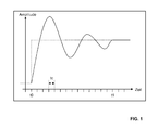
- Digital filters react to a sudden change in the amplitude of the input signal in principle with an in FIG. 1 exemplified output signal.
- the amplitude of the filter input signal is shown as a dashed line and undergoes a sudden change at time t0.
- the output signal of the filter shown as a solid line, is characterized by a time-delayed increase of the amplitude to a value that is greater than the amplitude of the input signal and then returns to the amplitude of the input signal at time t1.
- 1 shown oscillation of the filter output signal is referred to as a compensation process or as a settling of the filter, the time t1-t0 as settling time, over a certain number of clock steps tc, in the example shown 14 clock steps tc, extends.
- the invention is based on the recognition that this compensation process or the settling time can be shortened by the clock frequency of the filter for the period after an amplitude jump at the input is increased to a value which is a multiple above the clock frequency of the A / D converter.
- the number of clock steps required to equalize or tune the filter is thus passed through in a shorter period of time, and the output of the filter can be used earlier for signal detection.
- a tissue stimulator perception unit comprises an A / D converter which samples an analog signal at a sample clock and converts it into a digital signal and a digital filter whose input is connected to the output of the A / D converter and which has a Filtering clock performs a filtering of the digital signal, wherein for a certain period of time T, the filter clock is a multiple of the sampling clock.
- the period T is adjustable.
- the period T begins with the end of separation of the sensing unit from the electrode during and after a stimulation pulse.
- the filter clock during the period T is preferably twice to ten times the sampling clock.
- the analog signal undergoes a preamplifier and an analog filter prior to sampling.
- the perception unit is part of a tissue stimulator, such as a cardiac pacemaker, defibrillator, cardioverter or neurostimulator, which may also be designed as implantable devices.
- a tissue stimulator such as a cardiac pacemaker, defibrillator, cardioverter or neurostimulator, which may also be designed as implantable devices.
- Such a tissue stimulator comprises, in addition to the perception unit, at least one electrode terminal which is connected via a switch to the perception unit and directly to a stimulation unit, a clock providing a sampling clock and a filter clock, and a control unit operatively connected to the switch, the perception unit, the stimulation unit and the clock is.
- the control unit of the tissue stimulator is further configured to initiate an opening of the switch for at least the duration of delivery of one or more stimulation pulses while outside of this period the switch is closed.
- control unit is designed to cause the timer to increase the filter clock and maintain the sampling clock for a certain period of time T after the switch is closed again.
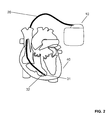
- FIG. 2 shows a heart stimulator (10) which is connected via an electrode connection with an electrically conductive insulated electrode line (20).
- the distal end of the electrode lead has one or more electrodes (31, 32) for receiving electrical signals from the heart (40).
- FIG. 3 shows the further construction of the heart stimulator (10).
- the heart stimulator includes a sensing unit (130) and a stimulation unit (140) connected to and controlled by a control unit (150).
- the input of the perception unit (130) is connected to the electrode terminal (110) via a switch (120) controlled by the control unit (150).
- the output of the stimulation unit (140) is also connected to the electrode terminal (110).
- the heart stimulator includes in FIG. 3 not shown, an electrical energy source, for example in the form of a battery or a rechargeable battery, the perception unit, stimulation unit and control unit supplied with energy.
- an electrical energy source for example in the form of a battery or a rechargeable battery
- the perception unit for example in the form of a battery or a rechargeable battery
- the stimulation unit supplied with energy.
- the heart stimulator also includes a clock generator (160) which provides clock signals and is controllable by the control unit (150).
- the perception unit (130) detects the electric signals of the heart recorded with the electrode and evaluates them for the purpose of recognizing physiological events. For example, electrical signals from an electrode placed in the ventricle above a certain amplitude threshold value are recognized as a natural contraction of the ventricle and transmitted to the control unit.
- the controller (150) in the absence of a natural contraction of the ventricle, may cause the stimulation unit (140) to deliver one or more electrical pulses to stimulate the heart.
- the control unit causes the opening of the otherwise closed switch (120), whereby the perception unit (130) is electrically separated from the electrode terminal (110).
- the controller (150) Upon delivery of the stimulation pulse, the controller (150) causes the switch (120) to close, thereby reconnecting the sensing unit (130) to the electrode terminal (110).
- the switch (120) is also referred to as a blanking switch.
- the separation of the perception stage (130) from the electrode terminal (110) is also referred to as analog blanking.
- a heart stimulator This basic structure and further embodiments of a heart stimulator are well known from the prior art.
- the perception of electrical signals of the heart and the stimulation can, as in FIG. 2 represented by two electrodes at the distal end of the electrode line and is referred to as bipolar signal detection or bipolar stimulation.
- a unipolar signal detection or stimulation can take place in which the electrode line has only one electrode at the distal end and the electrically conductive housing of the heart stimulator replaces the second electrode.
- the heart stimulator may have multiple sensing and stimulation units.
- the input of the perception unit (130) is connected to the electrode connection (110) via the blanking switch (120).
- the electrical signal received by the electrode passes through a preamplifier (131) and an analog filter (132) and is subsequently converted into a digital signal by an A / D converter (133).
- the A / D converter (133) further includes an input for the sample clock (161) necessary for the A / D conversion, which is provided by the clock (160) is characterized by a sampling frequency.
- the electrical signal received by the electrode first passes through the analog filter and is then fed via the preamplifier to the A / D converter.
- the analog preamplifier (131) and the analog filter (132) are not necessarily required for the implementation of the invention and may also be omitted.
- the digital signal at the output of the A / D converter is updated after each clock step to the time and value discrete sample value of the analog input signal and then filtered with a digital filter (134).
- the digital filter also has an input for a filter clock (162), which is also provided by the clock (160) and is characterized by a filter clock frequency.
- the output signal of the perception unit (130) is supplied to a signal processing unit, not shown here, for further processing.
- the output of the signal processing unit is connected to the control unit (150).
- the signal processing unit may also be part of the control unit (150).
Landscapes
- Health & Medical Sciences (AREA)
- Life Sciences & Earth Sciences (AREA)
- Animal Behavior & Ethology (AREA)
- General Health & Medical Sciences (AREA)
- Biomedical Technology (AREA)
- Nuclear Medicine, Radiotherapy & Molecular Imaging (AREA)
- Radiology & Medical Imaging (AREA)
- Veterinary Medicine (AREA)
- Public Health (AREA)
- Engineering & Computer Science (AREA)
- Cardiology (AREA)
- Heart & Thoracic Surgery (AREA)
- Neurology (AREA)
- Neurosurgery (AREA)
- Biophysics (AREA)
- Physiology (AREA)
- Electrotherapy Devices (AREA)
Abstract
Description
- Die Erfindung betrifft eine Wahrnehmungseinheit zur Verarbeitung elektrischer Signale eines menschlichen oder tierischen Körpers. Derartige Wahrnehmungseinheiten sind Bestandteil von Gewebestimulatoren wie Herzschrittmacher, Defibrillatoren, Cardioverter, Neurostimulatoren und dergleichen und dienen der Verarbeitung elektrischer Signale des Körpergewebes, die üblicherweise mittels Elektroden am, auf oder im Gewebe erfasst werden. Die Wahrnehmungseinheit ist über einen Elektrodenanschluss mit einer solchen Elektrode verbunden und beinhaltet zumindest einen Analog-Digital-Wandler (A/D-Wandler) und eine digitale Filterstufe. Die weitere Verarbeitung der Ausgangssignale der Wahrnehmungseinheit umfasst zumindest eine Bewertung der Signalamplitude, so werden beispielsweise elektrische Signale des Körpergewebes mit einer Amplitude oberhalb eines bestimmten Schwellwertes als natürliche Aktivität erkannt und bestimmten physiologischen Ereignissen anhand ihrer Charakteristik zugeordnet. Zur Stimulation des Körpergewebes enthält der Gewebestimulator eine Stimulationseinheit, über die ein oder mehrere elektrische Impulse über die Elektrode an das Körpergewebe abgegeben werden. Da die Amplitude der Stimulationsimpulse üblicherweise ein Mehrfaches der Amplituden der natürlichen elektrischen Gewebeaktivität beträgt, wird mindestens für die Dauer der Stimulation die Verbindung der Wahrnehmungseinheit zur Elektrode unterbrochen (z.B. bei einer Stimulationsimpulsdauer von 1ms kann diese Zeit der Trennung der Wahrnehmungseinheit von der Elektrode 8 bis 20ms betragen). Stimulationsimpulse verursachen an der Elektrode im Elektrolyten bzw. dem umgebenden Gewebe Polarisationseffekte (Umladungseffekte an der Grenzschicht zw. Elektrodenoberfläche und dem Elektrolyten), die zu einem Sprung der Amplitude des Eingangssignals der Wahrnehmungseinheit führen können, wenn diese nach der Stimulation wieder mit der Elektrode verbunden wird. Insbesondere Filter der Wahrnehmungseinheit reagieren auf diesen Sprung der Amplitude des Eingangssignals mit einer Sprungantwort, die sich als länger andauernde erhöhte Amplitude des Ausgangssignals der Wahrnehmungseinheit manifestiert und auch als Stimulationsartefakt bezeichnet wird. Solche Stimulationsartefakte können die Funktion des Gewebestimulators negativ beeinflussen, weil ein Stimulationsartefakt fälschlicherweise als natürliche elektrische Gewebeaktivität fehl interpretiert werden kann. Daher werden im Stand der Technik die Ausgangssignale der Wahrnehmungseinheit für eine bestimmte Zeitdauer nach der Stimulation von der Signalerkennung ausgeschlossen, was auch als digitales Blanking bezeichnet wird.. Nachteilig daran ist, dass tatsächliche natürliche Aktivitäten des Körpergewebes während der Zeitdauer des digitalen Blanking nicht erkannt werden können.
- Die vorliegende Erfindung löst die Aufgabe, eine Wahrnehmungseinheit zu schaffen, die diesen Nachteil überwindet und die eine frühere Signalerkennung nach einer Stimulation ermöglicht.
- Üblicherweise werden zeitkontinuierliche analoge Signale bei der A/D-Wandlung in der Wahrnehmungseinheit mit einer bestimmten Abtastfrequenz abgetastet und in digital codierte zeit- und wertdiskrete Abtastwerte umgewandelt. Die Abtastfrequenz wird dem A/D-Wandler als Taktfrequenz zugeführt. Mit jedem Taktschritt der Taktfrequenz stellt der A/D-Wandler einen neuen Abtastwert bereit. Bei der nachfolgenden digitalen Filterung werden die Abtastwerte gemäß dem gewählten Filteralgorithmus mathematischen Operationen wie Multiplikation und/oder Addition mit Filterkoeffizienten unterworfen, wobei die gleiche Taktfrequenz wie bei der A/D-Wandlung verwendet wird. Das digitale Filter liefert somit mit jedem Taktschritt für den am Eingang vorliegenden Abtastwert einen modifizierten Abtastwert am Ausgang.
- Digitale Filter reagieren auf eine sprunghafte Änderung der Amplitude des Eingangssignals prinzipbedingt mit einem in
Figur 1 beispielhaft dargestellten Ausgangssignal. Der Amplitude des Filtereingangssignals ist als gestrichelte Linie dargestellt und erfährt zum Zeitpunkt t0 eine sprunghafte Änderung. Das als durchgehende Linie dargestellte Ausgangssignal des Filters ist gekennzeichnet durch ein zeitverzögertes Ansteigen der Amplitude auf einen Wert, der über der Amplitude des Eingangssignals liegt und sich danach der Amplitude des Eingangssignals zum Zeitpunkt t1 wieder annähert. Die inFigur 1 dargestellte Oszillation des Filterausgangssignals wird als Ausgleichsvorgang oder auch als Einschwingen des Filters bezeichnet, die Zeitdauer t1-t0 als Einschwingzeit, die sich über eine bestimmte Anzahl von Taktschritten tc, im dargestellten Beispiel 14 Taktschritte tc, erstreckt. Die Erfindung basiert auf der Erkenntnis, dass dieser Ausgleichsvorgang beziehungsweise die Einschwingzeit verkürzt werden kann, indem die Taktfrequenz des Filters für den Zeitraum nach einem Amplitudensprung am Eingang auf einen Wert vergrößert wird, der ein mehrfaches über der Taktfrequenz des A/D-Wandlers liegt. Die den Ausgleichsvorgang oder für das Einschwingen des Filters benötigte Anzahl von Taktschritten wird so in einer kürzeren Zeitdauer durchlaufen und das Ausgangssignal des Filters kann früher zur Signalerkennung verwendet werden. - Eine erfindungsgemäße Wahrnehmungseinheit für einen Gewebestimulator umfasst einen A/D-Wandler, der ein analoges Signal mit einem Abtasttakt abtastet und in ein digitales Signal umwandelt und ein digitales Filter, dessen Eingang mit dem Ausgang des A/D-Wandlers verbunden ist und das mit einem Filtertakt eine Filterung des digitalen Signals vornimmt, wobei für einen bestimmten Zeitraum T der Filtertakt ein Mehrfaches des Abtasttaktes beträgt.
- Bevorzugt ist der Zeitraum T einstellbar. In einer Ausführungsform beginnt der Zeitraum T mit dem Ende der Trennung der Wahrnehmungseinheit von der Elektrode während und nach einem Stimulationsimpuls. Der Filtertakt während des Zeitraumes T beträgt bevorzugt das Doppelte bis Zehnfache des Abtasttaktes.
- In einer weiteren Ausführungsform durchläuft das analoge Signal vor der Abtastung einen Vorverstärker und ein analoges Filter.
- Bevorzugt ist die Wahrnehmungseinheit Bestandteil eines Gewebestimulators, wie eines Herzschrittmachers, Defibrillators, Kardioverters oder Neurostimulators, die auch als implantierbare Geräte ausgebildet sein können.
- Ein solcher Gewebestimulator umfasst neben der Wahrnehmungseinheit mindestens einem Elektrodenanschluss, der über einen Schalter mit der Wahrnehmungseinheit und direkt mit einer Stimulationseinheit verbunden ist, einem Taktgeber, der einen Abtasttakt und einen Filtertakt bereitstellt und eine Steuereinheit, die mit Schalter, Wahrnehmungseinheit, Stimulationseinheit und Taktgeber wirkverbunden ist.
- Die Steuereinheit des Gewebestimulators ist weiterhin ausgebildet für mindestens die Zeitdauer der Abgabe eines oder mehrer Stimulationsimpulse ein Öffnen des Schalters zu veranlassen, während außerhalb dieser Zeitdauer der Schalter geschlossen ist.
- Weiterhin ist die Steuereinheit ausgebildet den Taktgeber für einen bestimmten Zeitraum T nach dem wieder Schließen des Schalters zu veranlassen, den Filtertakt zu erhöhen und den Abtasttakt beizubehalten..
- Die Erfindung soll nun anhand eines Ausführungsbeispiels mit Bezug auf die Figuren näher erläutert werden.
- Von den Figuren zeigen:
- Figur 1:
- den Amplitudenverlauf des Ausgangssignales eines digitalen Filters
- Figur 2:
- einen Herzstimulator
- Figur 3:
- den schematischen Aufbau eines Herzstimulators
-
Figur 2 zeigt einen Herzstimulator (10), der über einen Elektrodenanschluss mit einer elektrisch leitenden isolierten Elektrodenleitung (20) verbunden ist. Das distale Ende der Elektrodenleitung weist eine oder mehrere Elektroden (31, 32) zur Aufnahme elektrischer Signale des Herzens (40) auf. -
Figur 3 zeigt den weiteren Aufbau des Herzstimulators (10). - Der Herzstimulator beinhaltet eine Wahrnehmungseinheit (130) und eine Stimulationseinheit (140), die mit einer Steuereinheit (150) verbunden sind und durch diese gesteuert werden. Der Eingang der Wahrnehmungseinheit (130) ist über einen von der Steuereinheit (150) gesteuerten Schalter (120) mit dem Elektrodenanschluss (110) verbunden. Der Ausgang der Stimulationseinheit (140) ist ebenfalls mit dem Elektrodenanschluss (110) verbunden.
- Weiterhin beinhaltet der Herzstimulator in
Figur 3 nicht dargestellte eine elektrische Energiequelle, beispielsweise in Form einer Batterie oder eines Akkumulators, die Wahrnehmungseinheit, Stimulationseinheit und Steuereinheit mit Energie versorgt. - Der Herzstimulator beinhaltet außerdem einen Taktgeber (160), der Taktsignale bereitstellt und durch die Steuereinheit (150) steuerbar ist.
- Die Wahrnehmungseinheit (130) erfasst die mit der Elektrode aufgenommenen elektrischen Signale des Herzens und wertet diese zur Erkennung physiologischer Ereignisse aus. Beispielsweise werden elektrische Signale von einer im Ventrikel platzierten Elektrode oberhalb eines bestimmten Amplitudenschwellwertes als natürliche Kontraktion des Ventrikels erkannt und an die Steuereinheit weitergegeben. Die Steuereinheit (150) kann beim Ausbleiben einer natürlichen Kontraktion des Ventrikels die Stimulationseinheit (140) veranlassen, einen oder mehrere elektrische Impulse zur Stimulation des Herzens abzugeben. Während der Abgabe eines Stimulationsimpulses veranlasst die Steuereinheit das Öffnen des ansonsten geschlossenen Schalters (120), womit die Wahrnehmungseinheit (130) elektrisch von Elektrodenanschluss (110) getrennt wird. Nach der Abgabe des Stimulationsimpulses veranlasst die Steuereinheit (150) das Schließen des Schalters (120), wodurch die Wahrnehmungseinheit (130) wieder mit dem Elektrodenanschluss (110) verbunden wird. Der Schalter (120) wird auch als Blankingschalter bezeichnet. Das Trennen der Wahrnehmungsstufe (130) vom Elektrodenanschluss (110) wird auch als analoges Blanking bezeichnet.
- Dieser grundsätzliche Aufbau und weitere Ausgestaltungen eines Herzstimulators sind aus dem Stand der Technik hinreichend bekannt. Die Wahrnehmung elektrischer Signale des Herzens und die Stimulation kann, wie in
Figur 2 dargestellt über zwei Elektroden am distalen Ende der Elektrodenleitung erfolgen und wird als bipolare Signalerfassung bzw. bipolare Stimulation bezeichnet. Alternativ kann auch eine unipolare Signalerfassung bzw. Stimulation erfolgen, bei der die Elektrodenleitung am distalen Ende nur eine Elektrode aufweist und das elektrisch leitende Gehäuse des Herzstimulators die zweite Elektrode ersetzt. Ebenso kann der Herzstimulator mehrere Wahrnehmungs- und Stimulationseinheiten aufweisen. - Im Folgenden wird auf den Aufbau der erfindungsgemäßen Wahrnehmungseinheit (130) von
Figur 3 eingegangen. - Der Eingang der Wahrnehmungseinheit (130) ist über den Blankingschalter (120) mit dem Elektrodenanschluss (110) verbunden. Das von der Elektrode aufgenommene elektrische Signal durchläuft einen Vorverstärker (131) und ein analoges Filter (132) und wird anschließend mit einem A/D-Wandler (133) in ein digitales Signal umgesetzt. Der A/D-Wandler (133) enthält weiterhin einen Eingang für den für die A/D Wandlung notwendigen Abtasttakt (161), welcher vom Taktgeber (160) bereitgestellt wird durch eine Abtastfrequenz gekennzeichnet ist. In einer nicht dargestellten alternativen Ausführungsform durchläuft das von der Elektrode aufgenommene elektrische Signal zuerst das analoge Filter und wird dann über den Vorverstärker dem A/D-Wandler zugeführt. Der analoge Vorverstärker (131) und das analoge Filter (132) sind für die Ausführung der Erfindung nicht zwingend erforderlich und können gegebenenfalls auch entfallen. Das digitale Signal am Ausgang des A/D-Wandlers wird nach jedem Taktschritt auf den zeit- und wertdiskreten Abtastwert des analogen Eingangssignales aktualisiert anschließend mit einem digitalen Filter (134) gefiltert. Auch das digitale Filter hat einen Eingang für einen Filtertakt (162), welcher ebenfalls vom Taktgeber (160) bereitgestellt wird und durch eine Filtertaktfrequenz gekennzeichnet ist. Vom Ausgang des digitalen Filters (134) wird das Ausgangssignal der Wahrnehmungseinheit (130) einer hier nicht dargestellten Signalverarbeitungseinheit zur weiteren Verarbeitung zugeführt. Der Ausgang der Signalverarbeitungseinheit ist mit der Steuereinheit (150) verbunden. Alternativ kann die Signalverarbeitungseinheit auch Bestandteil der Steuereinheit (150) sein.
- Die Arbeitsweise der Wahrnehmungseinheit (130) ist wie folgt:
- Solange durch die Stimulationseinheit (140) kein Stimulationsimpuls abgegeben wird, ist der Blankingschalter (120) geschlossen. A/D-Wandler (133) und das digitale Filter (134) erhalten vom Taktgeber (160) einen identischen Abtasttakt und Filtertakt mit der gleichen Abtastfrequenz und Filtertaktfrequenz. Während der Abgabe eines Stimulationsimpulses wird der Blankingschalter (120) geöffnet und nach der Abgabe eins Stimulationsimpulses zum Ende der programmierbaren analogen Blankingzeit wieder geschlossen. Mit dem erneuten Schließen des Blankingschalters (120) wird durch den Taktgeber der Filtertakt für das digitale Filter (134) für eine bestimmte Anzahl von Takten erhöht, und anschließend wieder auf den ursprünglichen Wert reduziert, während der Abtasttakt für den A/D-Wandler (133) unverändert bleibt. Alternativ kann der Filtertakt für das digitale Filter (134) direkt nach Abgabe eines Stimulationspulses erhöht werden.
- Das Filter mit der in
Figur 1 dargestellten Einschwingverhalten benötigt 14 Taktschritte nach dem Schließen des Blankingschalters für den Ausgleichsvorgang, was bei einem A/D-Wandler mit einer Abtastfrequenz von 500 Hz und einer Filtertaktfrequenz von 500 Hz zu einer Zeitdauer von 28 Millisekunden für das digitale Blanking führt. Dies bedeutet dass innerhalb von 28 Millisekunden nach einem Stimulationsimpuls keine Körpersignale detektiert werden können. Wird nun erfindungsgemäß die Filtertaktfrequenz für die ersten 14 Taktschritte nach dem Schließen des Blankingschalters um beispielsweise das 8-fache auf 4000 Hz vergrößert, ist der Ausgleichsvorgang bereits nach 3,5 Millisekunden abgeschlossen, so dass das digitale Blanking deutlich verkürzt werden kann.
Claims (10)
- Wahrnehmungseinheit (130) für einen Gewebestimulator (10), umfassend
einen A/D-Wandler (133), der ein analoges Signal mit einem Abtasttakt (161) abtastet und in ein digitales Signal umwandelt,
ein digitales Filter (134), dessen Eingang mit dem Ausgang des A/D-Wandlers verbunden ist und das mit einem Filtertakt (162) eine Filterung des digitalen Signals vornimmt,
dadurch gekennzeichnet,
dass für einen bestimmten Zeitraum T der Filtertakt (162) ein Mehrfaches des Abtasttaktes (161) beträgt. - Wahrnehmungseinheit (13 0) nach Anspruch 1,
dadurch gekennzeichnet
dass der Zeitraum T einstellbar ist. - Wahrnehmungseinheit (130) nach Anspruch 1 oder 2
dadurch gekennzeichnet
dass der Zeitraum T mit dem Ende eines Stimulationsimpulses beginnt. - Wahrnehmungseinheit (130) nach einem der vorgehenden Ansprüche,
dadurch gekennzeichnet
dass der Filtertakt (162) während des Zeitraumes T das Doppelte bis Zehnfache des Abtasttaktes (161) beträgt. - Wahrnehmungseinheit (130) nach einem der vorgehenden Ansprüche,
dadurch gekennzeichnet
dass das analoge Signal vor der Abtastung einen Vorverstärker (131) und ein analoges Filter (132) durchläuft. - Gewebestimulator (10) mit einer Wahrnehmungseinheit (130) nach einem der vorgehenden Ansprüche,
sowie mindestens einem Elektrodenanschluss (110) der über einen Schalter (120) mit der Wahrnehmungseinheit (130) und direkt mit einer Stimulationseinheit (140) verbunden ist,
einem Taktgeber (160) , der einen Abtasttakt (161) und einen Filtertakt (162) bereitstellt und
einer Steuereinheit (150), die mit Schalter (120), der Wahrnehmungseinheit (130), der Stimulationseinheit (140) und dem Taktgeber (160) wirkverbunden ist. - Gewebestimulator (10) nach Anspruch 6,
dadurch gekennzeichnet
dass die Steuereinheit (150) für die Zeitdauer der Abgabe eines oder mehrer Stimulationsimpulse ein Öffnen des Schalters (120) veranlasst, während außerhalb dieser Zeitdauer der Schalter (120) geschlossen ist. - Gewebestimulator (10) nach Anspruch 7,
dadurch gekennzeichnet
dass die Steuereinheit (150) den Taktgeber (160) für einen bestimmten Zeitraum T nach dem Öffnen des Schalters (120) veranlasst, den Filtertakt (162) zu erhöhen und den Abtasttakt (161) beizubehalten. - Gewebestimulator (10) nach einem der Ansprüche 6 bis 8
dadurch gekennzeichnet
dass er als Herzschrittmacher, Defibrillator, Kardioverter oder Neurostimulator ausgebildet ist. - Gewebestimulator (10) nach Anspruch 9
dadurch gekennzeichnet
dass er als implantierbares Gerät ausgebildet ist.
Applications Claiming Priority (1)
| Application Number | Priority Date | Filing Date | Title |
|---|---|---|---|
| US201361896138P | 2013-10-28 | 2013-10-28 |
Publications (2)
| Publication Number | Publication Date |
|---|---|
| EP2865415A1 true EP2865415A1 (de) | 2015-04-29 |
| EP2865415B1 EP2865415B1 (de) | 2016-08-31 |
Family
ID=51730379
Family Applications (1)
| Application Number | Title | Priority Date | Filing Date |
|---|---|---|---|
| EP14188787.7A Active EP2865415B1 (de) | 2013-10-28 | 2014-10-14 | Wahrnehmungseinheit für einen Gewebestimulator |
Country Status (2)
| Country | Link |
|---|---|
| US (1) | US9421375B2 (de) |
| EP (1) | EP2865415B1 (de) |
Families Citing this family (9)
| Publication number | Priority date | Publication date | Assignee | Title |
|---|---|---|---|---|
| US20180001107A1 (en) | 2016-07-01 | 2018-01-04 | Btl Holdings Limited | Aesthetic method of biological structure treatment by magnetic field |
| US10695575B1 (en) | 2016-05-10 | 2020-06-30 | Btl Medical Technologies S.R.O. | Aesthetic method of biological structure treatment by magnetic field |
| US11464993B2 (en) | 2016-05-03 | 2022-10-11 | Btl Healthcare Technologies A.S. | Device including RF source of energy and vacuum system |
| WO2020070492A1 (en) * | 2018-10-03 | 2020-04-09 | Oxford University Innovation Limited | Measurement of electrophysiological signals during stimulation of a target area of a body |
| US12558146B2 (en) | 2019-04-11 | 2026-02-24 | Btl Medical Solutions A.S. | Methods and devices for aesthetic treatment of biological structures by radiofrequency and magnetic energy |
| US12611545B2 (en) | 2020-05-04 | 2026-04-28 | Btl Healthcare Technologies A.S. | Device and method for unattended treatment of a patient |
| JP2023515722A (ja) | 2020-05-04 | 2023-04-13 | ビーティーエル ヘルスケア テクノロジーズ エー.エス. | 患者の非アテンド式治療のためのデバイスおよび方法 |
| US11878167B2 (en) | 2020-05-04 | 2024-01-23 | Btl Healthcare Technologies A.S. | Device and method for unattended treatment of a patient |
| US20260097226A1 (en) | 2024-10-08 | 2026-04-09 | Btl Medical Solutions A.S. | Devices and methods for application of a magnetic field to the nervous system |
Citations (3)
| Publication number | Priority date | Publication date | Assignee | Title |
|---|---|---|---|---|
| US20070146189A1 (en) * | 2005-12-28 | 2007-06-28 | Wesselink Willem A | DSP with variable sample frequency |
| EP2294978A1 (de) * | 2009-09-14 | 2011-03-16 | Imec | Adaptive Probenentnahme |
| US20130030486A1 (en) * | 2011-07-29 | 2013-01-31 | Medtronic, Inc. | Modification of av conduction time sampling rate |
Family Cites Families (3)
| Publication number | Priority date | Publication date | Assignee | Title |
|---|---|---|---|---|
| US4148320A (en) * | 1975-03-06 | 1979-04-10 | Kabushiki Kaisha Daini Seikosha | Artificial cardiac pacemaker |
| US4251831A (en) * | 1979-10-26 | 1981-02-17 | Kamath Bantval Y | Filter and system incorporating the filter for processing discrete samples of composite signals |
| US6704602B2 (en) | 1998-07-02 | 2004-03-09 | Medtronic, Inc. | Implanted medical device/external medical instrument communication utilizing surface electrodes |
-
2014
- 2014-10-13 US US14/512,492 patent/US9421375B2/en active Active
- 2014-10-14 EP EP14188787.7A patent/EP2865415B1/de active Active
Patent Citations (3)
| Publication number | Priority date | Publication date | Assignee | Title |
|---|---|---|---|---|
| US20070146189A1 (en) * | 2005-12-28 | 2007-06-28 | Wesselink Willem A | DSP with variable sample frequency |
| EP2294978A1 (de) * | 2009-09-14 | 2011-03-16 | Imec | Adaptive Probenentnahme |
| US20130030486A1 (en) * | 2011-07-29 | 2013-01-31 | Medtronic, Inc. | Modification of av conduction time sampling rate |
Also Published As
| Publication number | Publication date |
|---|---|
| EP2865415B1 (de) | 2016-08-31 |
| US9421375B2 (en) | 2016-08-23 |
| US20150119949A1 (en) | 2015-04-30 |
Similar Documents
| Publication | Publication Date | Title |
|---|---|---|
| EP2865415B1 (de) | Wahrnehmungseinheit für einen Gewebestimulator | |
| DE69218658T2 (de) | Implantierbares Defibrillator-System | |
| DE69614103T2 (de) | Mehrkanalige in die cochlear implantierte prothese mit flexibler steuerung von stimulus-wellenformen | |
| DE60122820T2 (de) | Vorrichtung zur Verringerung der Effekte von evozierten Potentialen bei Polarisationsmessungen in einem Herzschrittmachersystem mit automatischer Erfassung des Einfanges | |
| DE60125817T2 (de) | Mems-schaltkreis und verfahren für eine implantierbare medizinische vorrichtung | |
| DE19951491B4 (de) | Verringerung der Leistungsaufnahme bei medizinischen Vorrichtungen, bei denen mehrere digitale Signalprozessoren verwendet werden und zugehörige Verfahren | |
| DE2929498A1 (de) | Implantierbares elektronisches geraet | |
| DE60221859T2 (de) | Steuerung von rauschquellen während telemetrie | |
| EP2060299A1 (de) | Biventrikulärer Herzstimulator | |
| EP0508326A2 (de) | Implantierbarer Defibrillator | |
| DE2263834B2 (de) | Vorrichtung zum kontrollieren der von einem herzschrittmacher an die in das herz eingesetzten elektroden gelieferten spannung | |
| EP0444021B1 (de) | Herzschrittmacher | |
| EP3025759A1 (de) | Mrt-taugliches aktives implantierbares gerät | |
| EP2502646A2 (de) | Implantierbares Gerät | |
| EP2578268B1 (de) | Temperatursensor für ein implantierbares medizinisches Gerät | |
| EP1262143B1 (de) | Verfahren und Speichervorrichtung zur Speicherung von Herzrhythmusinformation | |
| DE3237199A1 (de) | Zeitbereichsverarbeitung interner physiologischer signale | |
| WO1991003272A1 (de) | Medizinisches gerät zur stimulation von gewebekontraktionen | |
| EP3476432B1 (de) | Vorrichtung zur hochspannungstherapie | |
| DE3248009A1 (de) | Schrittmach/abtast-herzschrittmacher mit drei elektroden | |
| DE102008020123A1 (de) | Ventrikulärer Herzstimulator | |
| DE60304984T2 (de) | Aktive implantierbare medizinische Vorrichtung mit Detektierung von evozierten Herzpotentialen, insbesondere Atrialpotentialen | |
| DE102019121719A1 (de) | Implantierbares Defibrillationssystem | |
| EP2308558B1 (de) | Biventrikulärer Herzstimulator | |
| DE102008002370A1 (de) | Herzstimulator zur Behandlung tachykarder Rhythmusstörungen eines Herzens |
Legal Events
| Date | Code | Title | Description |
|---|---|---|---|
| PUAI | Public reference made under article 153(3) epc to a published international application that has entered the european phase |
Free format text: ORIGINAL CODE: 0009012 |
|
| 17P | Request for examination filed |
Effective date: 20141014 |
|
| AK | Designated contracting states |
Kind code of ref document: A1 Designated state(s): AL AT BE BG CH CY CZ DE DK EE ES FI FR GB GR HR HU IE IS IT LI LT LU LV MC MK MT NL NO PL PT RO RS SE SI SK SM TR |
|
| AX | Request for extension of the european patent |
Extension state: BA ME |
|
| R17P | Request for examination filed (corrected) |
Effective date: 20151026 |
|
| RBV | Designated contracting states (corrected) |
Designated state(s): AL AT BE BG CH CY CZ DE DK EE ES FI FR GB GR HR HU IE IS IT LI LT LU LV MC MK MT NL NO PL PT RO RS SE SI SK SM TR |
|
| RIC1 | Information provided on ipc code assigned before grant |
Ipc: A61N 1/37 20060101ALI20160218BHEP Ipc: A61N 1/36 20060101ALI20160218BHEP Ipc: A61N 1/362 20060101ALI20160218BHEP Ipc: A61N 1/39 20060101AFI20160218BHEP |
|
| GRAP | Despatch of communication of intention to grant a patent |
Free format text: ORIGINAL CODE: EPIDOSNIGR1 |
|
| INTG | Intention to grant announced |
Effective date: 20160419 |
|
| GRAS | Grant fee paid |
Free format text: ORIGINAL CODE: EPIDOSNIGR3 |
|
| GRAA | (expected) grant |
Free format text: ORIGINAL CODE: 0009210 |
|
| AK | Designated contracting states |
Kind code of ref document: B1 Designated state(s): AL AT BE BG CH CY CZ DE DK EE ES FI FR GB GR HR HU IE IS IT LI LT LU LV MC MK MT NL NO PL PT RO RS SE SI SK SM TR |
|
| REG | Reference to a national code |
Ref country code: CH Ref legal event code: EP Ref country code: GB Ref legal event code: FG4D Free format text: NOT ENGLISH |
|
| REG | Reference to a national code |
Ref country code: IE Ref legal event code: FG4D Free format text: LANGUAGE OF EP DOCUMENT: GERMAN |
|
| REG | Reference to a national code |
Ref country code: DE Ref legal event code: R096 Ref document number: 502014001346 Country of ref document: DE |
|
| REG | Reference to a national code |
Ref country code: AT Ref legal event code: REF Ref document number: 824467 Country of ref document: AT Kind code of ref document: T Effective date: 20161015 |
|
| REG | Reference to a national code |
Ref country code: LT Ref legal event code: MG4D |
|
| REG | Reference to a national code |
Ref country code: NL Ref legal event code: MP Effective date: 20160831 |
|
| PG25 | Lapsed in a contracting state [announced via postgrant information from national office to epo] |
Ref country code: NO Free format text: LAPSE BECAUSE OF FAILURE TO SUBMIT A TRANSLATION OF THE DESCRIPTION OR TO PAY THE FEE WITHIN THE PRESCRIBED TIME-LIMIT Effective date: 20161130 Ref country code: LT Free format text: LAPSE BECAUSE OF FAILURE TO SUBMIT A TRANSLATION OF THE DESCRIPTION OR TO PAY THE FEE WITHIN THE PRESCRIBED TIME-LIMIT Effective date: 20160831 Ref country code: HR Free format text: LAPSE BECAUSE OF FAILURE TO SUBMIT A TRANSLATION OF THE DESCRIPTION OR TO PAY THE FEE WITHIN THE PRESCRIBED TIME-LIMIT Effective date: 20160831 Ref country code: RS Free format text: LAPSE BECAUSE OF FAILURE TO SUBMIT A TRANSLATION OF THE DESCRIPTION OR TO PAY THE FEE WITHIN THE PRESCRIBED TIME-LIMIT Effective date: 20160831 Ref country code: FI Free format text: LAPSE BECAUSE OF FAILURE TO SUBMIT A TRANSLATION OF THE DESCRIPTION OR TO PAY THE FEE WITHIN THE PRESCRIBED TIME-LIMIT Effective date: 20160831 |
|
| PG25 | Lapsed in a contracting state [announced via postgrant information from national office to epo] |
Ref country code: LV Free format text: LAPSE BECAUSE OF FAILURE TO SUBMIT A TRANSLATION OF THE DESCRIPTION OR TO PAY THE FEE WITHIN THE PRESCRIBED TIME-LIMIT Effective date: 20160831 Ref country code: GR Free format text: LAPSE BECAUSE OF FAILURE TO SUBMIT A TRANSLATION OF THE DESCRIPTION OR TO PAY THE FEE WITHIN THE PRESCRIBED TIME-LIMIT Effective date: 20161201 Ref country code: SE Free format text: LAPSE BECAUSE OF FAILURE TO SUBMIT A TRANSLATION OF THE DESCRIPTION OR TO PAY THE FEE WITHIN THE PRESCRIBED TIME-LIMIT Effective date: 20160831 Ref country code: BE Free format text: LAPSE BECAUSE OF NON-PAYMENT OF DUE FEES Effective date: 20161031 Ref country code: NL Free format text: LAPSE BECAUSE OF FAILURE TO SUBMIT A TRANSLATION OF THE DESCRIPTION OR TO PAY THE FEE WITHIN THE PRESCRIBED TIME-LIMIT Effective date: 20160831 Ref country code: ES Free format text: LAPSE BECAUSE OF FAILURE TO SUBMIT A TRANSLATION OF THE DESCRIPTION OR TO PAY THE FEE WITHIN THE PRESCRIBED TIME-LIMIT Effective date: 20160831 |
|
| PG25 | Lapsed in a contracting state [announced via postgrant information from national office to epo] |
Ref country code: EE Free format text: LAPSE BECAUSE OF FAILURE TO SUBMIT A TRANSLATION OF THE DESCRIPTION OR TO PAY THE FEE WITHIN THE PRESCRIBED TIME-LIMIT Effective date: 20160831 Ref country code: RO Free format text: LAPSE BECAUSE OF FAILURE TO SUBMIT A TRANSLATION OF THE DESCRIPTION OR TO PAY THE FEE WITHIN THE PRESCRIBED TIME-LIMIT Effective date: 20160831 |
|
| PG25 | Lapsed in a contracting state [announced via postgrant information from national office to epo] |
Ref country code: DK Free format text: LAPSE BECAUSE OF FAILURE TO SUBMIT A TRANSLATION OF THE DESCRIPTION OR TO PAY THE FEE WITHIN THE PRESCRIBED TIME-LIMIT Effective date: 20160831 Ref country code: BG Free format text: LAPSE BECAUSE OF FAILURE TO SUBMIT A TRANSLATION OF THE DESCRIPTION OR TO PAY THE FEE WITHIN THE PRESCRIBED TIME-LIMIT Effective date: 20161130 Ref country code: CZ Free format text: LAPSE BECAUSE OF FAILURE TO SUBMIT A TRANSLATION OF THE DESCRIPTION OR TO PAY THE FEE WITHIN THE PRESCRIBED TIME-LIMIT Effective date: 20160831 Ref country code: SM Free format text: LAPSE BECAUSE OF FAILURE TO SUBMIT A TRANSLATION OF THE DESCRIPTION OR TO PAY THE FEE WITHIN THE PRESCRIBED TIME-LIMIT Effective date: 20160831 Ref country code: PL Free format text: LAPSE BECAUSE OF FAILURE TO SUBMIT A TRANSLATION OF THE DESCRIPTION OR TO PAY THE FEE WITHIN THE PRESCRIBED TIME-LIMIT Effective date: 20160831 Ref country code: SK Free format text: LAPSE BECAUSE OF FAILURE TO SUBMIT A TRANSLATION OF THE DESCRIPTION OR TO PAY THE FEE WITHIN THE PRESCRIBED TIME-LIMIT Effective date: 20160831 Ref country code: PT Free format text: LAPSE BECAUSE OF FAILURE TO SUBMIT A TRANSLATION OF THE DESCRIPTION OR TO PAY THE FEE WITHIN THE PRESCRIBED TIME-LIMIT Effective date: 20170102 |
|
| REG | Reference to a national code |
Ref country code: DE Ref legal event code: R097 Ref document number: 502014001346 Country of ref document: DE |
|
| PG25 | Lapsed in a contracting state [announced via postgrant information from national office to epo] |
Ref country code: IT Free format text: LAPSE BECAUSE OF FAILURE TO SUBMIT A TRANSLATION OF THE DESCRIPTION OR TO PAY THE FEE WITHIN THE PRESCRIBED TIME-LIMIT Effective date: 20160831 |
|
| PLBE | No opposition filed within time limit |
Free format text: ORIGINAL CODE: 0009261 |
|
| STAA | Information on the status of an ep patent application or granted ep patent |
Free format text: STATUS: NO OPPOSITION FILED WITHIN TIME LIMIT |
|
| REG | Reference to a national code |
Ref country code: FR Ref legal event code: ST Effective date: 20170630 |
|
| PG25 | Lapsed in a contracting state [announced via postgrant information from national office to epo] |
Ref country code: FR Free format text: LAPSE BECAUSE OF NON-PAYMENT OF DUE FEES Effective date: 20161102 |
|
| 26N | No opposition filed |
Effective date: 20170601 |
|
| PG25 | Lapsed in a contracting state [announced via postgrant information from national office to epo] |
Ref country code: LU Free format text: LAPSE BECAUSE OF NON-PAYMENT OF DUE FEES Effective date: 20161014 Ref country code: SI Free format text: LAPSE BECAUSE OF FAILURE TO SUBMIT A TRANSLATION OF THE DESCRIPTION OR TO PAY THE FEE WITHIN THE PRESCRIBED TIME-LIMIT Effective date: 20160831 |
|
| REG | Reference to a national code |
Ref country code: BE Ref legal event code: MM Effective date: 20161031 |
|
| PG25 | Lapsed in a contracting state [announced via postgrant information from national office to epo] |
Ref country code: HU Free format text: LAPSE BECAUSE OF FAILURE TO SUBMIT A TRANSLATION OF THE DESCRIPTION OR TO PAY THE FEE WITHIN THE PRESCRIBED TIME-LIMIT; INVALID AB INITIO Effective date: 20141014 |
|
| PG25 | Lapsed in a contracting state [announced via postgrant information from national office to epo] |
Ref country code: MT Free format text: LAPSE BECAUSE OF FAILURE TO SUBMIT A TRANSLATION OF THE DESCRIPTION OR TO PAY THE FEE WITHIN THE PRESCRIBED TIME-LIMIT Effective date: 20160831 Ref country code: MC Free format text: LAPSE BECAUSE OF FAILURE TO SUBMIT A TRANSLATION OF THE DESCRIPTION OR TO PAY THE FEE WITHIN THE PRESCRIBED TIME-LIMIT Effective date: 20160831 Ref country code: CY Free format text: LAPSE BECAUSE OF FAILURE TO SUBMIT A TRANSLATION OF THE DESCRIPTION OR TO PAY THE FEE WITHIN THE PRESCRIBED TIME-LIMIT Effective date: 20160831 Ref country code: MK Free format text: LAPSE BECAUSE OF FAILURE TO SUBMIT A TRANSLATION OF THE DESCRIPTION OR TO PAY THE FEE WITHIN THE PRESCRIBED TIME-LIMIT Effective date: 20160831 Ref country code: IS Free format text: LAPSE BECAUSE OF FAILURE TO SUBMIT A TRANSLATION OF THE DESCRIPTION OR TO PAY THE FEE WITHIN THE PRESCRIBED TIME-LIMIT Effective date: 20160831 |
|
| PG25 | Lapsed in a contracting state [announced via postgrant information from national office to epo] |
Ref country code: TR Free format text: LAPSE BECAUSE OF FAILURE TO SUBMIT A TRANSLATION OF THE DESCRIPTION OR TO PAY THE FEE WITHIN THE PRESCRIBED TIME-LIMIT Effective date: 20160831 Ref country code: AL Free format text: LAPSE BECAUSE OF FAILURE TO SUBMIT A TRANSLATION OF THE DESCRIPTION OR TO PAY THE FEE WITHIN THE PRESCRIBED TIME-LIMIT Effective date: 20160831 |
|
| GBPC | Gb: european patent ceased through non-payment of renewal fee |
Effective date: 20181014 |
|
| PG25 | Lapsed in a contracting state [announced via postgrant information from national office to epo] |
Ref country code: GB Free format text: LAPSE BECAUSE OF NON-PAYMENT OF DUE FEES Effective date: 20181014 |
|
| REG | Reference to a national code |
Ref country code: AT Ref legal event code: MM01 Ref document number: 824467 Country of ref document: AT Kind code of ref document: T Effective date: 20191014 |
|
| PG25 | Lapsed in a contracting state [announced via postgrant information from national office to epo] |
Ref country code: AT Free format text: LAPSE BECAUSE OF NON-PAYMENT OF DUE FEES Effective date: 20191014 |
|
| P01 | Opt-out of the competence of the unified patent court (upc) registered |
Effective date: 20230608 |
|
| REG | Reference to a national code |
Ref country code: CH Ref legal event code: U11 Free format text: ST27 STATUS EVENT CODE: U-0-0-U10-U11 (AS PROVIDED BY THE NATIONAL OFFICE) Effective date: 20251101 |
|
| PGFP | Annual fee paid to national office [announced via postgrant information from national office to epo] |
Ref country code: DE Payment date: 20251020 Year of fee payment: 12 |
|
| PGFP | Annual fee paid to national office [announced via postgrant information from national office to epo] |
Ref country code: CH Payment date: 20251101 Year of fee payment: 12 |
|
| PGFP | Annual fee paid to national office [announced via postgrant information from national office to epo] |
Ref country code: IE Payment date: 20251021 Year of fee payment: 12 |