EP2863665A1 - Standortaktualisierungsverfahren für ein endgerät zur unterstützung mehrerer funkzugangstechnologien - Google Patents
Standortaktualisierungsverfahren für ein endgerät zur unterstützung mehrerer funkzugangstechnologien Download PDFInfo
- Publication number
- EP2863665A1 EP2863665A1 EP13806553.7A EP13806553A EP2863665A1 EP 2863665 A1 EP2863665 A1 EP 2863665A1 EP 13806553 A EP13806553 A EP 13806553A EP 2863665 A1 EP2863665 A1 EP 2863665A1
- Authority
- EP
- European Patent Office
- Prior art keywords
- network
- base station
- virtual base
- tunnel
- radio access
- Prior art date
- Legal status (The legal status is an assumption and is not a legal conclusion. Google has not performed a legal analysis and makes no representation as to the accuracy of the status listed.)
- Granted
Links
- 238000005516 engineering process Methods 0.000 title claims abstract description 31
- 238000000034 method Methods 0.000 title claims abstract description 27
- 230000007774 longterm Effects 0.000 claims description 4
- 238000004891 communication Methods 0.000 description 27
- 230000006870 function Effects 0.000 description 12
- 238000010586 diagram Methods 0.000 description 7
- 230000008569 process Effects 0.000 description 6
- 230000005540 biological transmission Effects 0.000 description 5
- 230000015654 memory Effects 0.000 description 5
- 238000012545 processing Methods 0.000 description 5
- 230000008859 change Effects 0.000 description 4
- 101150114331 MME1 gene Proteins 0.000 description 3
- 239000000969 carrier Substances 0.000 description 3
- 238000010295 mobile communication Methods 0.000 description 3
- 238000011160 research Methods 0.000 description 3
- 230000000694 effects Effects 0.000 description 2
- 238000012986 modification Methods 0.000 description 2
- 230000004048 modification Effects 0.000 description 2
- 241000760358 Enodes Species 0.000 description 1
- 238000003491 array Methods 0.000 description 1
- 230000000295 complement effect Effects 0.000 description 1
- 230000004044 response Effects 0.000 description 1
- 238000001228 spectrum Methods 0.000 description 1
- 238000012546 transfer Methods 0.000 description 1
Images


Classifications
-
- H—ELECTRICITY
- H04—ELECTRIC COMMUNICATION TECHNIQUE
- H04W—WIRELESS COMMUNICATION NETWORKS
- H04W4/00—Services specially adapted for wireless communication networks; Facilities therefor
- H04W4/02—Services making use of location information
-
- H—ELECTRICITY
- H04—ELECTRIC COMMUNICATION TECHNIQUE
- H04W—WIRELESS COMMUNICATION NETWORKS
- H04W36/00—Hand-off or reselection arrangements
- H04W36/14—Reselecting a network or an air interface
-
- H—ELECTRICITY
- H04—ELECTRIC COMMUNICATION TECHNIQUE
- H04W—WIRELESS COMMUNICATION NETWORKS
- H04W36/00—Hand-off or reselection arrangements
- H04W36/14—Reselecting a network or an air interface
- H04W36/144—Reselecting a network or an air interface over a different radio air interface technology
- H04W36/1446—Reselecting a network or an air interface over a different radio air interface technology wherein at least one of the networks is unlicensed
-
- H—ELECTRICITY
- H04—ELECTRIC COMMUNICATION TECHNIQUE
- H04W—WIRELESS COMMUNICATION NETWORKS
- H04W60/00—Affiliation to network, e.g. registration; Terminating affiliation with the network, e.g. de-registration
- H04W60/005—Multiple registrations, e.g. multihoming
-
- H—ELECTRICITY
- H04—ELECTRIC COMMUNICATION TECHNIQUE
- H04W—WIRELESS COMMUNICATION NETWORKS
- H04W68/00—User notification, e.g. alerting and paging, for incoming communication, change of service or the like
- H04W68/02—Arrangements for increasing efficiency of notification or paging channel
-
- H—ELECTRICITY
- H04—ELECTRIC COMMUNICATION TECHNIQUE
- H04W—WIRELESS COMMUNICATION NETWORKS
- H04W76/00—Connection management
- H04W76/30—Connection release
- H04W76/34—Selective release of ongoing connections
-
- H—ELECTRICITY
- H04—ELECTRIC COMMUNICATION TECHNIQUE
- H04W—WIRELESS COMMUNICATION NETWORKS
- H04W76/00—Connection management
- H04W76/10—Connection setup
- H04W76/12—Setup of transport tunnels
-
- H—ELECTRICITY
- H04—ELECTRIC COMMUNICATION TECHNIQUE
- H04W—WIRELESS COMMUNICATION NETWORKS
- H04W76/00—Connection management
- H04W76/10—Connection setup
- H04W76/15—Setup of multiple wireless link connections
- H04W76/16—Involving different core network technologies, e.g. a packet-switched [PS] bearer in combination with a circuit-switched [CS] bearer
-
- H—ELECTRICITY
- H04—ELECTRIC COMMUNICATION TECHNIQUE
- H04W—WIRELESS COMMUNICATION NETWORKS
- H04W88/00—Devices specially adapted for wireless communication networks, e.g. terminals, base stations or access point devices
- H04W88/02—Terminal devices
- H04W88/06—Terminal devices adapted for operation in multiple networks or having at least two operational modes, e.g. multi-mode terminals
Definitions
- the present invention relates to radio communication, and more specifically, relates to a method for updating a location when a user equipment (UE) capable of simultaneously accessing different networks maintains access only to a base station of a particular network.
- UE user equipment
- a link between existing multiples radio access technologies (RATs) or multiple systems have focused on supporting mobility in terms of access to a network and authentication.
- RATs multiples radio access technologies
- LTE long term evolution
- Wi-Fi wireless fidelity
- QoS quality of service
- a service of a radio operator through an LTE core network in terms of managing networks of mobile carriers.
- An object of the present invention devised to solve the problem lies in a method of updating a location by a UE that supports a plurality of radio access technologies.
- Another object of the present invention is to provide a UE that supports a plurality of radio access technologies and updates a location.
- the object of the present invention can be achieved by providing a method for updating a location by a user equipment (UE) supporting a plurality of radio access technologies, the method including releasing a radio resource connection with a base station of a first network to maintain access only to a base station of a second network using a second radio access technology, the UE being capable of simultaneously accessing different networks using a first radio access technology and the second radio access technology, establishing a layer 3 (L3) tunnel with a virtual base station of the first network while maintaining access only to the base station of the second network, and transmitting an updated location of the UE to the virtual base station of the first network to which the L3 tunnel is established.
- UE user equipment
- the method may further include receiving a paging message from the virtual base station of the first network, and establishing a radio resource connection with the virtual base station of the first network according to the paging message.
- the method further may further include acquiring an Internet protocol (IP) address of the virtual base station of the first network, wherein an IP address of the virtual base station of the first network to which the L3 tunnel is established is the acquired IP address of the virtual base station of the first network.
- IP Internet protocol
- the method may further include receiving, a message for handover request to perform a handover the base station of the second network, from the virtual base station of the first network in a case in which the base station of the second network is needed to perform the handover due to movement of the UE, and performing the handover according to the handover request, and establishing the L3 tunnel with another virtual base station of the first network.
- the case in which the base station of the second network is needed to perform the handover corresponds to a case in which the UE is located in another bases station of the second network establishing a tunnel to another virtual base station of the first network due to movement of the UE.
- the first network may include a long term evolution (LTE) network
- the second network may include a Wi-Fi network.
- a user equipment (UE) of updating a location the UE supports a plurality of radio access technologies and updating a location, including a processor configured to release connection to radio resources of a base station of a first network to maintain access only to a base station of a second network using the second radio access technology, the UE being capable of simultaneously accessing different networks using a first radio access technology and a second radio access technology; and establishes an L3 tunnel with a virtual base station of the first network while maintaining access only to the base station of the second network, and a transmitter configured to transmit an updated location of the UE to the virtual base station of the first network to which the L3 tunnel is established.
- a processor configured to release connection to radio resources of a base station of a first network to maintain access only to a base station of a second network using the second radio access technology, the UE being capable of simultaneously accessing different networks using a first radio access technology and a second radio access technology; and establishes an L3 tunnel with a virtual base station of the first network while maintaining access only to the
- publicized structures and apparatuses may be omitted or illustrated in a block diagram form centered on core functions of the respective structures and apparatuses in order to prevent a concept of the present invention from being ambiguous.
- the same component is described using the same reference numeral throughout the specification.
- a UE commonly refers to a mobile or stationary device at a user end such as a terminal, a mobile station (MS), an advanced mobile station (AMS), or the like in description below.
- a base station commonly refers to an arbitrary node at a network end which communicates with the terminal such as Node B, eNode B, Base station, an access point (AP), or the like.
- the UE may receive information through downlink from the base station, and transmit information through uplink.
- the information transmitted or received by the UE includes data and a variety of control information.
- various physical channels are present based on a type and a use of the information transmitted or received by the UE.
- CDMA code division multiple access
- FDMA frequency division multiple access
- TDMA time division multiple access
- OFDMA orthogonal frequency division multiple access
- SC-FDMA single carrier frequency division multiple access
- CDMA may be implemented by a radio technology such as Universal Terrestrial Radio Access (UTRA) or CDMA2000.
- TDMA may be implemented by a radio technology such as Global System for Mobile communications (GSM)/General Packet Radio Service (GPRS)/Enhanced Data Rates for GSM Evolution (EDGE).
- GPRS General Packet Radio Service
- EDGE Enhanced Data Rates for GSM Evolution
- OFDMA may be implemented by a radio technology such as IEEE 802.11 (Wi-Fi), IEEE 802.16 (WiMAX), IEEE 802-20, E-UTRA (Evolved UTRA), or the like.
- UTRA is a part of Universal Mobile Telecommunications System (UMTS).
- 3rd Generation Partnership Project (3GPP) LTE is a part of Evolved UMTS (E-UMTS) using E-UTRA, and adopts OFDMA in downlink and SC-FDMA in uplink.
- LTE-advance (LTE-A) is an evolution from 3GPP LTE.
- FIG. 1 is a block diagram illustrating a structure of a base station (BS) 105 and a user equipment (UE) 110 in a wireless communication system 100.
- BS base station
- UE user equipment
- the wireless communication system 100 may include one or more BSs and/or one or more UEs.
- the BS 105 may include a transmission (Tx) data processor 115, a symbol modulator 120, a transmitter 125, a Tx/Rx antenna 130, a processor 180, a memory 185, a receiver 190, a symbol demodulator 195, and a reception (Rx) data processor 197.
- the UE 110 may include a Tx data processor 165, a symbol modulator 170, a transmitter 175, a Tx/Rx antenna 135, a processor 155, a memory 160, a receiver 140, a symbol demodulator 145, and an Rx data processor 150.
- each of the BS 105 and the UE 110 includes the Tx/Rx antennas 130 and 135, respectively, each the BS 105 and the UE 110 includes a plurality of Tx/Rx antennas.
- the BS 105 and the UE 110 according to the present invention support a multiple input multiple output (MIMO) system.
- the BS 105 according to the present invention may support both single user-MIMO (SU-MIMO) and multi user-MIMO (MU-MIMO) schemes.
- SU-MIMO single user-MIMO
- MU-MIMO multi user-MIMO
- one transceiver may be replace transmitter 125 and receiver 190, likewise, in the UE 110, one transceiver may be replace transmitter 175 and receiver 140.
- the Tx data processor 115 receives traffic data, formats and codes the received traffic data, and interleaves and modulates (or symbol-maps) the coded traffic data to provide modulated symbols ("data symbols").
- the symbol modulator 120 receives and processes the data symbols and pilot symbols to provide a stream of symbols.
- the symbol modulator 120 multiplexes the data and pilot symbols and transmits the multiplexed data and pilot symbols to the transmitter 125.
- each transmitted symbol may be a data symbol, a pilot symbol, or a zero signal value.
- pilot symbols may be consecutively transmitted.
- the pilot symbols may each be a frequency division multiplexing (FDM) symbol, an orthogonal frequency division multiplexing (OFDM) symbol, a time division multiplexing (TDM) symbol, or a code division multiplexing (CDM) symbol.
- FDM frequency division multiplexing
- OFDM orthogonal frequency division multiplexing
- TDM time division multiplexing
- CDM code division multiplexing
- the transmitter 125 receives the stream of symbols, converts the stream into one or more analog signals, and further adjusts (e.g., amplifies, filters, and frequency-upconverts) the analog signals to generate a downlink signal appropriate for transmission via a radio channel. Then the Tx antenna 130 transmits the generated downlink signal to the UE 110.
- the Rx antenna 135 receives the downlink signal from the BS 105 and provides the received signal to the receiver 140.
- the receiver 140 adjusts (e.g., filters, amplifies, and frequency-downconverts) the received signal and digitizes the adjusted signal to acquire samples.
- the symbol demodulator 145 demodulates the received pilot symbols and provides the pilot symbols to the processor 155 for channel estimation.
- the symbol demodulator 145 receives a frequency response estimated value for downlink from the processor 155, data-demodulates the received data symbols to acquires data symbol estimated values (which is estimated values of the transmitted data symbols), and provides the data symbol estimated values to the Rx data processor 150.
- the Rx data processor 150 demodulates (i.e., symbol-demaps), deinterleaves, and decodes the data symbol estimated values to recover the transmitted traffic data.
- Processing operations by the symbol demodulator 145 and the Rx data processor 150 are complementary to processing operations of the symbol modulator 120 and the Tx data processor 115 in the BS 105, respectively.
- the Tx data processor 165 of the UE 110 processes traffic data to provide data symbols.
- the symbol modulator 170 may receive and modulate the data symbols and provide a stream of the symbols to the transmitter 175.
- the transmitter 175 receives and processes the stream of symbols to generate an uplink signal.
- the Rx antenna 135 transmits the generate uplink signal to the BS 105.
- an uplink signal from the UE 110 is received by the Rx antenna 130, and the receiver 190 processes the received uplink signal to acquire samples. Then the symbol demodulator 195 processes the samples to provide pilot symbols and data symbol estimated values which are received for downlink.
- the reception (Rx) data processor 197 processes the data symbol estimated values to recover the traffic data transmitted from the UE 110.
- the processors 155 and 180 of the UE 110 and the BS 105 order (e.g., controls, manipulates, manages, etc.) operations of the UE 110 and the BS 105, respectively.
- the processors 155 and 180 may be respectively connected to the memories 160 and 185 which store program codes and data.
- the memories 160 and 185 are respectively connected to the processors 155 and 180 and store an operating system, application, and general files.
- the processors 155 and 180 may be referred to as a controller, a microcontroller, a microprocessor, a microcomputer, or the like.
- the processors 155 and 180 may each be embodied by hardware, firmware, software, or a combination thereof.
- the processors 155 and 180 may include application specific integrated circuits (ASICs), digital signal processors (DSPs), digital signal processing devices (DSPDs), programmable logic devices (PLDs), field programmable gate arrays (FPGAs), or the like which is configured to execute the present invention.
- ASICs application specific integrated circuits
- DSPs digital signal processors
- DSPDs digital signal processing devices
- PLDs programmable logic devices
- FPGAs field programmable gate arrays
- firmware or software may be configured in the form of a module, a procedure, a function, etc. which perform function or operations according to the present invention.
- Firmware or software configured to implement the present invention may be included in the processors 155 and 180 or stored in the memories 160 and 185 and driven by the processors 155 and 180.
- Layers of a wireless interface protocol between wireless communication systems (network) of the UE and the BS may be classified into a first layer L1, a second layer L2, and a third layer L3 based on three lower layers of an open system interconnection (OSI) model that is well known in a communication system.
- a physical layer belongs to the first layer L1 and provides an information transfer service through a physical channel.
- a radio resource control (RRC) layer belongs to the third layer (L3) and provides control radio resources between the UE and a network.
- the UE and the BS may exchange RRC messages through a wireless communication network and an RRC layer.
- the processor 155 of the UE 110 and the processor 180 of the BS 105 perform an operation for processing signals and data except for a function of receiving or transmitting signals by the UE 110 and the BS 105 or a storing function.
- the processors 155 and 180 will not be specially stated. Unless the processors 155 and 180 are not stated, a series of operations such as data processing but not the function of transmitting or receiving signals and the storing function may be performed.
- a link between existing multiples radio access technologies (RATs) or multiple systems have focused on supporting mobility in terms of access to a network and authentication.
- RATs multiples radio access technologies
- LTE long term evolution
- Wi-Fi long term evolution
- QoS quality of service
- FIG. 2 illustrates a network structure for describing a linkage structure of a first communication system (for example, an LTE system) and a second communication system (for example, a Wi-Fi system).
- a first communication system for example, an LTE system
- a second communication system for example, a Wi-Fi system
- backhaul control connection or wireless control connection may be present between an AP and an eNB through a backbone network (for example, a P-GW or evolved packet core (EPC)).
- a UE may support both the first communication system (or first communication RAT) that uses a first radio communication scheme and the second communication system (or second communication RAT) that uses a second radio communication scheme through a link between a plurality of communication networks.
- the first communication RAT or the first communication system may be referred to as a primary RAT or a primary system, respectively
- the second communication RAT or the second communication system may be referred to as a secondary RAT or a secondary system, respectively.
- the UE may be configured to support the LTE (or LTE-A) system and the Wi-Fi system (a local area communication system such as WLAN/802.11) at the same time.
- the primary system has a wider coverage area, and may correspond to a network for transmission of control information.
- Examples of the primary system include WiMAX or LTE.
- the secondary system may correspond to a network having a small coverage area and a system for data transmission.
- Examples of the secondary network include a wireless local area network (WLAN) system such as Wi-Fi.
- WLAN wireless local area network
- the LTE system is at least in the idle mode during Wi-Fi communication.
- LTE connection is not needed during Wi-Fi connection in an integrated network. Therefore, the present invention proposes a method of controlling the idle mode through location management when the UE is connected only to the Wi-Fi network.
- the present invention proposes a method of receiving a paging message of the LTE system when the UE is connected only to the Wi-Fi network and a location update scheme therefor.
- LTE may be used as the primary RAT
- Wi-Fi a device to device (D2D) communication scheme, or the like
- D2D device to device
- the secondary RAT for example, Wi-Fi
- the secondary RAT are managed in LTE.
- a multi-RAT state machine will be described.
- a UE in the LTE network is in one of three states such as a turn-off (TO) state, an idle (IDL) state, and an active (A) state.
- a UE in the Wi-Fi network is in one of three states such as the turn-off (TO) state, a sleep (SLP) state, and the active (A) state.
- Combined states of the multiple RATs may be configured by integrally managing connection states which have been separately operated.
- a UE may be indicated by (LTE network state, Wi-Fi network state), for example, (TO, TO), (IDL, TO), (IDL, SLP), (TO, SLP), ..., (A, A).
- a network registration state may also be integrally managed in an EPS Mobility Management (EMM) state.
- EMM_Connected is a mobile management entity (MME)-registered state (idle, active).
- MME mobile management entity
- MEMM_Connected is a newly proposed state.
- the MEMM_Connected state is a network-registered state in any one of the RATs and excludes (TO, TO) state.
- This state is a state of being EMM-attached to an MME corresponding to an overlay BS of an AP in a case of Wi-Fi only.
- a virtual base station may be included in a network and linked to the AP so that the MME may perform paging operation to the virtual base station.
- Integrated management includes authentication, paging, IP management, and the like.
- FIG. 3 illustrates a scheme of supporting mobility related to a multi-radio (multi-RAT) power management issue.
- Wi-Fi signal forward function SFF
- WiMAX SFF performs functions of the virtual AP and the VeNB.
- a VeNB connected to a Wi-Fi AP has information about an overlay eNB.
- a UE may access a virtual AP in the network (reassociation), and perform Wi-Fi handover to a target AP via the virtual AP using the inter-access point protocol (IAPP).
- IAPP inter-access point protocol
- the UE may be registered in the VeNB in the network (that is, registered through an RRC connection establishment procedure), and perform handover from the VeNB to the target eNB. Paging may be provided in a similar manner.
- the UE receives a paging message through an AP of the Wi-Fi network, is registered in the VeNB, and is handed over to an actual eNB.
- MEMM Multi-Radio Enhanced Mobility Manaement
- EMM_connected state refers to a state in which a UE is registered in an MME. Previously, EMM registration cannot be performed when accessing Wi-Fi only. When Wi-Fi is installed by an operator, integrated location management may be performed through Wi-Fi.
- an L3 tunnel is established between the VeNB and the UE during access through a Wi-Fi AP to logically enable location registration through virtual BS.
- a point of this proposal is a scheme of including the VeNB in the network to support mobility through the VeNB.
- a scheme of registering the UE in the MME through the VeNB is a technology excluded from an existing the WiMAX forum scheme.
- the VeNB does not have a wireless (radio) function and provides a function of connection to the MME or another eNB.
- idle mode mobility enhancement there are three main operations for the UE in the idle mode, and the three operations in the idle mode are as below.
- Termination of the idle mode by the UE (network entry/reentry)
- FIG. 4 is related to a scheme of efficiently supporting idle mode mobility enhancement, in particular, location registration (tracking area update).
- Tracking area update is used for two purposes.
- a primary purpose of tracking area update is to manage routing path in mobile IP-based transmission.
- a second purpose is to actually manage a location of the UE in the network.
- the UE reports the change to the MME using a non-access spectrum message.
- the network may recognize a tracking area in which the UE is present based on the report.
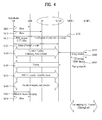
- FIG. 4 illustrates the scheme of supporting mobility related to the multi-radio (multi-RAT) power management issue.
- a multi-radio UE may exchange data with an eNB in the LTE network in S405, and exchange data with an AP in the Wi-Fi network simultaneously or at another time in S410. Thereafter, the multi-radio UE may enter the idle mode by releasing RRC from the LTE network to exchange data only via the Wi-Fi network in S415. The eNB performing operation of releasing RRC with the multi-radio UE may inform MME1 that the multi-radio UE enters the idle mode in S420. Thereafter, the multi-radio UE establishes a tunnel to a VeNB through the AP in S425. The L3 tunnel is established between the VeNB and the UE while the multi-radio UE performs access through a Wi-Fi AP, which logically enables location registration through the VeNB.
- the multi-radio UE performs location update with the VeNB in S430.
- the VeNB delivers an updated location of the multi-radio UE to MME2 in S435.
- MME2 determines whether to change a serving MME of the multi-radio UE based on the updated location of the multi-radio UE, and requests MME1 to change the serving MME of the multi-radio UE when, for example, the serving MME needs to be changed from MME2 to MME1 in S440. Thereafter, MME2 requests that the VeNB perform paging in S445.
- the VeNB transmits a paging message to the multi-radio UE in S450.
- the multi-radio UE receiving the paging message from the VeNB performs an RRC connection establishment operation with the VeNB in S455.
- the multi-radio UE performs a handover operation such as handover request while being RRC-connected to the VeNB in S460.
- the multi-radio UE may exchange a random access/ranging message in S465 and data in S470 with the eNB.
- the L3 tunnel is established between the VeNB and the UE to logically enable location registration through the VeNB.
- a scheme of transmitting data (scheme of establishing the L3 tunnel) to the VeNB is examined.
- the WiMAX forum uses Media Independent Handover Function (MIHF) of IEEE 802.21 or a scheme in which a server in the network automatically performs setting.
- MIHF Media Independent Handover Function
- the present invention proposes the following scheme. First, 1) a superordinate eNB informs the multi-radio UE of an IP address of a VeNB in advance. Subsequently, 2) the multi-radio UE may acquire this information from an eNB camped on at the end. In this case, the IP address of the VeNB may be received through standard change, or reported by the server in the network. 3) When the UE may perform Wi-Fi offloading without a request from the multi-radio UE, the IP address of the VeNB may be reported to the multi-radio UE in advance. When the IP address of the VeNB is absent, the IP address may be periodically updated.
- a scheme of updating information about the IP address of the VeNB will be described with reference to FIG. 5 .
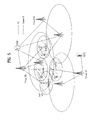
- FIG. 5 illustrates a scheme of updating the IP address of the VeNB.
- an extended service set (ESS) of a Wi-Fi AP may share MAC information.
- the ESS is a set of APs and thus may be assumed to be in the same VeNB.
- the IP address of the VeNB is updated.
- the multi-radio UE searches for an eNB.
- the multi-radio UE searches for an actual eNB and performs update.
- a location is updated through an existing VeNB.
- the VeNB requests that the UE perform handover when changing an AP, handover establishes the L3 tunnel to a new VeNB, and the new VeNB registers the UE in an upper-layer MME of the new VeNB. In this way, the UE may update an address of the VeNB.
- the method for updating a location by a UE that supports a plurality of radio access technologies is industrially applicable to various communication systems such as 3GPP LTE, LTE-A. IEEE 802, and the like.
Applications Claiming Priority (2)
| Application Number | Priority Date | Filing Date | Title |
|---|---|---|---|
| US201261661353P | 2012-06-19 | 2012-06-19 | |
| PCT/KR2013/005396 WO2013191461A1 (ko) | 2012-06-19 | 2013-06-19 | 복수의 무선접속 기술을 지원 가능한 단말이 위치 갱신을 수행하는 방법 |
Publications (3)
| Publication Number | Publication Date |
|---|---|
| EP2863665A1 true EP2863665A1 (de) | 2015-04-22 |
| EP2863665A4 EP2863665A4 (de) | 2016-03-30 |
| EP2863665B1 EP2863665B1 (de) | 2020-12-09 |
Family
ID=49769001
Family Applications (1)
| Application Number | Title | Priority Date | Filing Date |
|---|---|---|---|
| EP13806553.7A Active EP2863665B1 (de) | 2012-06-19 | 2013-06-19 | Standortaktualisierungsverfahren für ein endgerät zur unterstützung mehrerer funkzugangstechnologien |
Country Status (3)
| Country | Link |
|---|---|
| US (1) | US9516462B2 (de) |
| EP (1) | EP2863665B1 (de) |
| WO (1) | WO2013191461A1 (de) |
Cited By (1)
| Publication number | Priority date | Publication date | Assignee | Title |
|---|---|---|---|---|
| WO2019064068A1 (en) * | 2017-09-28 | 2019-04-04 | Lenovo (Singapore) Pte. Ltd. | METHOD AND APPARATUS FOR MANAGING DUAL RECORDING WITH A PLURALITY OF NETWORKS IN ONE OR MORE RADIO COMMUNICATION SYSTEMS |
Families Citing this family (8)
| Publication number | Priority date | Publication date | Assignee | Title |
|---|---|---|---|---|
| US9936474B2 (en) * | 2014-08-22 | 2018-04-03 | Qualcomm Incorporated | Paging over non-cellular and cellular RATs |
| WO2016048219A1 (en) * | 2014-09-26 | 2016-03-31 | Telefonaktiebolaget L M Ericsson (Publ) | Establishing a dedicated control plane tunnel |
| US10484924B2 (en) * | 2014-11-07 | 2019-11-19 | Kyocera Corporation | Core network apparatus, radio terminal, and base station |
| US10098064B2 (en) * | 2015-05-22 | 2018-10-09 | Cable Television Laboratories, Inc. | Virtual cells for radio access network (RAN) sharing |
| KR102461929B1 (ko) | 2015-09-25 | 2022-11-02 | 삼성전자주식회사 | 다수의 무선 접속 인터페이스를 지원하는 이동 통신 시스템에서 스트리밍 서비스 데이터를 수신하는 장치 및 방법 |
| GB2553417A (en) | 2016-06-30 | 2018-03-07 | Tait Ltd | Integration of physical and virtual LMR networks |
| CN111182652B (zh) * | 2018-11-09 | 2023-12-01 | 北京三星通信技术研究有限公司 | 网络连接方法、相应的装置和电子设备 |
| US10764721B1 (en) * | 2020-02-24 | 2020-09-01 | Verizon Patent And Licensing Inc. | Systems and methods for UE location and mobility |
Family Cites Families (24)
| Publication number | Priority date | Publication date | Assignee | Title |
|---|---|---|---|---|
| JP3607466B2 (ja) * | 1997-09-05 | 2005-01-05 | 株式会社東芝 | ルータ装置及び制御フレーム処理方法 |
| JP3645140B2 (ja) * | 1999-12-28 | 2005-05-11 | 株式会社エヌ・ティ・ティ・ドコモ | 移動通信システム |
| KR100455130B1 (ko) * | 2000-12-23 | 2004-11-08 | 엘지전자 주식회사 | 가상 에이알피 패킷을 이용한 프록시 에이알피 동작 방법 |
| US20030012151A1 (en) * | 2001-07-12 | 2003-01-16 | Dan Vassilovski | System and method for paging for voice over IP |
| CN1839592A (zh) * | 2003-09-11 | 2006-09-27 | 富士通株式会社 | 包中继装置 |
| US7715340B2 (en) * | 2004-03-04 | 2010-05-11 | At&T Corp. | Method and apparatus for enabling IP mobility with high speed access and network intelligence in communication networks |
| JP4266962B2 (ja) * | 2005-06-16 | 2009-05-27 | キヤノン株式会社 | 通信装置、その制御方法及びプログラム |
| US7986915B1 (en) * | 2006-02-24 | 2011-07-26 | Nortel Networks Limited | Method and system for a wireless multi-hop relay network |
| US8151322B2 (en) * | 2006-05-16 | 2012-04-03 | A10 Networks, Inc. | Systems and methods for user access authentication based on network access point |
| US20090325608A1 (en) | 2008-06-27 | 2009-12-31 | Qualcomm Incorporated | Methods and systems for multi-mode paging |
| CN102138317B (zh) * | 2008-08-04 | 2015-08-26 | Nec欧洲有限公司 | 用于在移动通信系统中促进通信的方法和移动通信系统 |
| US8891441B2 (en) * | 2008-09-04 | 2014-11-18 | Intel Corporation | L2 tunneling-based low latency single radio handoffs |
| JP2010088055A (ja) * | 2008-10-02 | 2010-04-15 | Fujitsu Ltd | 通信システム、移動機、端末管理装置および通信方法 |
| US8477775B2 (en) * | 2009-05-14 | 2013-07-02 | Avaya Inc. | Unifying local and mobility network identifiers |
| US20110013559A1 (en) * | 2009-07-16 | 2011-01-20 | Motorola, Inc. | Wireless communication via a tunnel through a serving access network |
| US20110231654A1 (en) * | 2010-03-16 | 2011-09-22 | Gurudas Somadder | Method, system and apparatus providing secure infrastructure |
| US9161233B2 (en) | 2010-03-30 | 2015-10-13 | Qualcomm Incorporated | Method and apparatus to facilitate support for multi-radio coexistence |
| WO2011152683A2 (ko) | 2010-06-04 | 2011-12-08 | 엘지전자 주식회사 | 다중 무선접속 방식을 지원하는 무선통신 시스템에서 통신을 수행하는 장치 및 그 방법 |
| KR101377967B1 (ko) * | 2010-10-20 | 2014-03-25 | 엘지전자 주식회사 | 접근점을 이용한 다중 무선 접속 시스템에서 데이터를 송수신하는 방법 및 장치 |
| WO2012059130A1 (en) * | 2010-11-04 | 2012-05-10 | Nokia Siemens Networks Oy | Virtual radio networks |
| CN102130826A (zh) * | 2010-11-25 | 2011-07-20 | 华为技术有限公司 | 报文的发送方法和装置 |
| US9137198B2 (en) * | 2011-10-21 | 2015-09-15 | Hewlett-Packard Development Company, L.P. | Centralized configuration with dynamic distributed address management |
| US9331899B2 (en) * | 2013-03-13 | 2016-05-03 | American Megatrends, Inc. | Scalable BMC management stacks using virtual networks on single physical network device |
| US10033595B2 (en) * | 2013-08-27 | 2018-07-24 | Futurewei Technologies, Inc. | System and method for mobile network function virtualization |
-
2013
- 2013-06-19 EP EP13806553.7A patent/EP2863665B1/de active Active
- 2013-06-19 US US14/409,908 patent/US9516462B2/en not_active Expired - Fee Related
- 2013-06-19 WO PCT/KR2013/005396 patent/WO2013191461A1/ko active Application Filing
Cited By (3)
| Publication number | Priority date | Publication date | Assignee | Title |
|---|---|---|---|---|
| WO2019064068A1 (en) * | 2017-09-28 | 2019-04-04 | Lenovo (Singapore) Pte. Ltd. | METHOD AND APPARATUS FOR MANAGING DUAL RECORDING WITH A PLURALITY OF NETWORKS IN ONE OR MORE RADIO COMMUNICATION SYSTEMS |
| WO2019064064A3 (en) * | 2017-09-28 | 2019-06-20 | Lenovo (Singapore) Pte. Ltd. | Method and apparatus for managing dual registration with multiple networks in one or more radio communication systems |
| US10536918B2 (en) | 2017-09-28 | 2020-01-14 | Lenovo (Singapore) Pte. Ltd. | Method and apparatus for managing dual registration with multiple networks in one or more radio communication systems |
Also Published As
| Publication number | Publication date |
|---|---|
| EP2863665B1 (de) | 2020-12-09 |
| US20150189468A1 (en) | 2015-07-02 |
| US9516462B2 (en) | 2016-12-06 |
| WO2013191461A1 (ko) | 2013-12-27 |
| EP2863665A4 (de) | 2016-03-30 |
Similar Documents
| Publication | Publication Date | Title |
|---|---|---|
| EP2863665B1 (de) | Standortaktualisierungsverfahren für ein endgerät zur unterstützung mehrerer funkzugangstechnologien | |
| US10045384B2 (en) | Method for managing link failure of user equipment simultaneously connected to multiple rats and device for performing same | |
| JP6915038B2 (ja) | CIoT(cellular internet of things)機能の非互換性による登録拒否 | |
| US10021629B2 (en) | Method for transiting status of network node upon request of user equipment in multi-radio access technology environment, and apparatus therefor | |
| US10595355B2 (en) | Method and apparatus for establishing a connection in a wireless communication system | |
| US9686786B2 (en) | Method for updating base station information in converged network supporting multiple communication systems, and device therefor | |
| US9992802B2 (en) | Method for performing connecting operation with multiple communication systems in network including multiple communication systems interworking with each other, and apparatus for same | |
| US11737001B2 (en) | Layer 2 relay user equipment mobility | |
| JP2021500800A (ja) | ネットワークスライシングと発展型パケットコア接続性との間の相互作用を可能にするためのメカニズム | |
| US9860835B2 (en) | Method for cell selection in multi-rat environment | |
| US20160227396A1 (en) | Method for setting and updating tracking area in c-ran and apparatus therefor | |
| US9622151B2 (en) | Method for managing information about on/off small cells in radio access system and apparatus for supporting same | |
| US11785576B2 (en) | Relay discovery in wireless communication systems | |
| KR20160005005A (ko) | 복수의 통신시스템에서 기지국을 탐색하는 방법 및 이를 위한 장치 | |
| US10798648B2 (en) | Method for performing PLMN selection and device supporting the same | |
| US9743356B2 (en) | Method and apparatus for supporting state mode transition or performing state mode transition in plural communication system convergence networks | |
| EP4013181A1 (de) | Kommunikationssystem, kommunikationsendgerät und netzwerk | |
| WO2021142820A1 (en) | Timer based nr 5g service search |
Legal Events
| Date | Code | Title | Description |
|---|---|---|---|
| PUAI | Public reference made under article 153(3) epc to a published international application that has entered the european phase |
Free format text: ORIGINAL CODE: 0009012 |
|
| 17P | Request for examination filed |
Effective date: 20150107 |
|
| AK | Designated contracting states |
Kind code of ref document: A1 Designated state(s): AL AT BE BG CH CY CZ DE DK EE ES FI FR GB GR HR HU IE IS IT LI LT LU LV MC MK MT NL NO PL PT RO RS SE SI SK SM TR |
|
| AX | Request for extension of the european patent |
Extension state: BA ME |
|
| DAX | Request for extension of the european patent (deleted) | ||
| RA4 | Supplementary search report drawn up and despatched (corrected) |
Effective date: 20160301 |
|
| RIC1 | Information provided on ipc code assigned before grant |
Ipc: H04W 4/02 20090101ALI20160224BHEP Ipc: H04W 36/14 20090101ALI20160224BHEP Ipc: H04W 8/08 20090101AFI20160224BHEP Ipc: H04W 68/02 20090101ALI20160224BHEP Ipc: H04W 88/06 20090101ALN20160224BHEP Ipc: H04W 76/02 20090101ALN20160224BHEP Ipc: H04W 60/00 20090101ALI20160224BHEP Ipc: H04W 76/06 20090101ALI20160224BHEP |
|
| STAA | Information on the status of an ep patent application or granted ep patent |
Free format text: STATUS: EXAMINATION IS IN PROGRESS |
|
| 17Q | First examination report despatched |
Effective date: 20190513 |
|
| REG | Reference to a national code |
Ref country code: DE Ref legal event code: R079 Ref document number: 602013074651 Country of ref document: DE Free format text: PREVIOUS MAIN CLASS: H04W0008080000 Ipc: H04W0076340000 |
|
| GRAP | Despatch of communication of intention to grant a patent |
Free format text: ORIGINAL CODE: EPIDOSNIGR1 |
|
| STAA | Information on the status of an ep patent application or granted ep patent |
Free format text: STATUS: GRANT OF PATENT IS INTENDED |
|
| RIC1 | Information provided on ipc code assigned before grant |
Ipc: H04W 36/14 20090101ALI20200602BHEP Ipc: H04W 4/12 20090101ALI20200602BHEP Ipc: H04W 60/00 20090101ALI20200602BHEP Ipc: H04W 88/06 20090101ALI20200602BHEP Ipc: H04W 4/02 20180101ALI20200602BHEP Ipc: H04W 76/34 20180101AFI20200602BHEP |
|
| INTG | Intention to grant announced |
Effective date: 20200630 |
|
| GRAS | Grant fee paid |
Free format text: ORIGINAL CODE: EPIDOSNIGR3 |
|
| GRAA | (expected) grant |
Free format text: ORIGINAL CODE: 0009210 |
|
| STAA | Information on the status of an ep patent application or granted ep patent |
Free format text: STATUS: THE PATENT HAS BEEN GRANTED |
|
| AK | Designated contracting states |
Kind code of ref document: B1 Designated state(s): AL AT BE BG CH CY CZ DE DK EE ES FI FR GB GR HR HU IE IS IT LI LT LU LV MC MK MT NL NO PL PT RO RS SE SI SK SM TR |
|
| REG | Reference to a national code |
Ref country code: GB Ref legal event code: FG4D |
|
| REG | Reference to a national code |
Ref country code: AT Ref legal event code: REF Ref document number: 1344671 Country of ref document: AT Kind code of ref document: T Effective date: 20201215 Ref country code: CH Ref legal event code: EP |
|
| REG | Reference to a national code |
Ref country code: DE Ref legal event code: R096 Ref document number: 602013074651 Country of ref document: DE |
|
| REG | Reference to a national code |
Ref country code: IE Ref legal event code: FG4D |
|
| PG25 | Lapsed in a contracting state [announced via postgrant information from national office to epo] |
Ref country code: GR Free format text: LAPSE BECAUSE OF FAILURE TO SUBMIT A TRANSLATION OF THE DESCRIPTION OR TO PAY THE FEE WITHIN THE PRESCRIBED TIME-LIMIT Effective date: 20210310 Ref country code: NO Free format text: LAPSE BECAUSE OF FAILURE TO SUBMIT A TRANSLATION OF THE DESCRIPTION OR TO PAY THE FEE WITHIN THE PRESCRIBED TIME-LIMIT Effective date: 20210309 Ref country code: RS Free format text: LAPSE BECAUSE OF FAILURE TO SUBMIT A TRANSLATION OF THE DESCRIPTION OR TO PAY THE FEE WITHIN THE PRESCRIBED TIME-LIMIT Effective date: 20201209 Ref country code: FI Free format text: LAPSE BECAUSE OF FAILURE TO SUBMIT A TRANSLATION OF THE DESCRIPTION OR TO PAY THE FEE WITHIN THE PRESCRIBED TIME-LIMIT Effective date: 20201209 |
|
| REG | Reference to a national code |
Ref country code: AT Ref legal event code: MK05 Ref document number: 1344671 Country of ref document: AT Kind code of ref document: T Effective date: 20201209 |
|
| PG25 | Lapsed in a contracting state [announced via postgrant information from national office to epo] |
Ref country code: SE Free format text: LAPSE BECAUSE OF FAILURE TO SUBMIT A TRANSLATION OF THE DESCRIPTION OR TO PAY THE FEE WITHIN THE PRESCRIBED TIME-LIMIT Effective date: 20201209 Ref country code: LV Free format text: LAPSE BECAUSE OF FAILURE TO SUBMIT A TRANSLATION OF THE DESCRIPTION OR TO PAY THE FEE WITHIN THE PRESCRIBED TIME-LIMIT Effective date: 20201209 Ref country code: BG Free format text: LAPSE BECAUSE OF FAILURE TO SUBMIT A TRANSLATION OF THE DESCRIPTION OR TO PAY THE FEE WITHIN THE PRESCRIBED TIME-LIMIT Effective date: 20210309 |
|
| REG | Reference to a national code |
Ref country code: NL Ref legal event code: MP Effective date: 20201209 |
|
| PG25 | Lapsed in a contracting state [announced via postgrant information from national office to epo] |
Ref country code: NL Free format text: LAPSE BECAUSE OF FAILURE TO SUBMIT A TRANSLATION OF THE DESCRIPTION OR TO PAY THE FEE WITHIN THE PRESCRIBED TIME-LIMIT Effective date: 20201209 Ref country code: HR Free format text: LAPSE BECAUSE OF FAILURE TO SUBMIT A TRANSLATION OF THE DESCRIPTION OR TO PAY THE FEE WITHIN THE PRESCRIBED TIME-LIMIT Effective date: 20201209 |
|
| REG | Reference to a national code |
Ref country code: LT Ref legal event code: MG9D |
|
| PG25 | Lapsed in a contracting state [announced via postgrant information from national office to epo] |
Ref country code: PT Free format text: LAPSE BECAUSE OF FAILURE TO SUBMIT A TRANSLATION OF THE DESCRIPTION OR TO PAY THE FEE WITHIN THE PRESCRIBED TIME-LIMIT Effective date: 20210409 Ref country code: SK Free format text: LAPSE BECAUSE OF FAILURE TO SUBMIT A TRANSLATION OF THE DESCRIPTION OR TO PAY THE FEE WITHIN THE PRESCRIBED TIME-LIMIT Effective date: 20201209 Ref country code: RO Free format text: LAPSE BECAUSE OF FAILURE TO SUBMIT A TRANSLATION OF THE DESCRIPTION OR TO PAY THE FEE WITHIN THE PRESCRIBED TIME-LIMIT Effective date: 20201209 Ref country code: LT Free format text: LAPSE BECAUSE OF FAILURE TO SUBMIT A TRANSLATION OF THE DESCRIPTION OR TO PAY THE FEE WITHIN THE PRESCRIBED TIME-LIMIT Effective date: 20201209 Ref country code: EE Free format text: LAPSE BECAUSE OF FAILURE TO SUBMIT A TRANSLATION OF THE DESCRIPTION OR TO PAY THE FEE WITHIN THE PRESCRIBED TIME-LIMIT Effective date: 20201209 Ref country code: CZ Free format text: LAPSE BECAUSE OF FAILURE TO SUBMIT A TRANSLATION OF THE DESCRIPTION OR TO PAY THE FEE WITHIN THE PRESCRIBED TIME-LIMIT Effective date: 20201209 Ref country code: SM Free format text: LAPSE BECAUSE OF FAILURE TO SUBMIT A TRANSLATION OF THE DESCRIPTION OR TO PAY THE FEE WITHIN THE PRESCRIBED TIME-LIMIT Effective date: 20201209 |
|
| PG25 | Lapsed in a contracting state [announced via postgrant information from national office to epo] |
Ref country code: AT Free format text: LAPSE BECAUSE OF FAILURE TO SUBMIT A TRANSLATION OF THE DESCRIPTION OR TO PAY THE FEE WITHIN THE PRESCRIBED TIME-LIMIT Effective date: 20201209 Ref country code: PL Free format text: LAPSE BECAUSE OF FAILURE TO SUBMIT A TRANSLATION OF THE DESCRIPTION OR TO PAY THE FEE WITHIN THE PRESCRIBED TIME-LIMIT Effective date: 20201209 |
|
| REG | Reference to a national code |
Ref country code: DE Ref legal event code: R097 Ref document number: 602013074651 Country of ref document: DE |
|
| PG25 | Lapsed in a contracting state [announced via postgrant information from national office to epo] |
Ref country code: IS Free format text: LAPSE BECAUSE OF FAILURE TO SUBMIT A TRANSLATION OF THE DESCRIPTION OR TO PAY THE FEE WITHIN THE PRESCRIBED TIME-LIMIT Effective date: 20210409 |
|
| PLBE | No opposition filed within time limit |
Free format text: ORIGINAL CODE: 0009261 |
|
| STAA | Information on the status of an ep patent application or granted ep patent |
Free format text: STATUS: NO OPPOSITION FILED WITHIN TIME LIMIT |
|
| PG25 | Lapsed in a contracting state [announced via postgrant information from national office to epo] |
Ref country code: IT Free format text: LAPSE BECAUSE OF FAILURE TO SUBMIT A TRANSLATION OF THE DESCRIPTION OR TO PAY THE FEE WITHIN THE PRESCRIBED TIME-LIMIT Effective date: 20201209 Ref country code: AL Free format text: LAPSE BECAUSE OF FAILURE TO SUBMIT A TRANSLATION OF THE DESCRIPTION OR TO PAY THE FEE WITHIN THE PRESCRIBED TIME-LIMIT Effective date: 20201209 |
|
| 26N | No opposition filed |
Effective date: 20210910 |
|
| PG25 | Lapsed in a contracting state [announced via postgrant information from national office to epo] |
Ref country code: DK Free format text: LAPSE BECAUSE OF FAILURE TO SUBMIT A TRANSLATION OF THE DESCRIPTION OR TO PAY THE FEE WITHIN THE PRESCRIBED TIME-LIMIT Effective date: 20201209 Ref country code: ES Free format text: LAPSE BECAUSE OF FAILURE TO SUBMIT A TRANSLATION OF THE DESCRIPTION OR TO PAY THE FEE WITHIN THE PRESCRIBED TIME-LIMIT Effective date: 20201209 Ref country code: SI Free format text: LAPSE BECAUSE OF FAILURE TO SUBMIT A TRANSLATION OF THE DESCRIPTION OR TO PAY THE FEE WITHIN THE PRESCRIBED TIME-LIMIT Effective date: 20201209 |
|
| PG25 | Lapsed in a contracting state [announced via postgrant information from national office to epo] |
Ref country code: MC Free format text: LAPSE BECAUSE OF FAILURE TO SUBMIT A TRANSLATION OF THE DESCRIPTION OR TO PAY THE FEE WITHIN THE PRESCRIBED TIME-LIMIT Effective date: 20201209 |
|
| REG | Reference to a national code |
Ref country code: CH Ref legal event code: PL |
|
| GBPC | Gb: european patent ceased through non-payment of renewal fee |
Effective date: 20210619 |
|
| REG | Reference to a national code |
Ref country code: BE Ref legal event code: MM Effective date: 20210630 |
|
| PG25 | Lapsed in a contracting state [announced via postgrant information from national office to epo] |
Ref country code: LU Free format text: LAPSE BECAUSE OF NON-PAYMENT OF DUE FEES Effective date: 20210619 |
|
| PG25 | Lapsed in a contracting state [announced via postgrant information from national office to epo] |
Ref country code: LI Free format text: LAPSE BECAUSE OF NON-PAYMENT OF DUE FEES Effective date: 20210630 Ref country code: IE Free format text: LAPSE BECAUSE OF NON-PAYMENT OF DUE FEES Effective date: 20210619 Ref country code: GB Free format text: LAPSE BECAUSE OF NON-PAYMENT OF DUE FEES Effective date: 20210619 Ref country code: CH Free format text: LAPSE BECAUSE OF NON-PAYMENT OF DUE FEES Effective date: 20210630 |
|
| PG25 | Lapsed in a contracting state [announced via postgrant information from national office to epo] |
Ref country code: IS Free format text: LAPSE BECAUSE OF FAILURE TO SUBMIT A TRANSLATION OF THE DESCRIPTION OR TO PAY THE FEE WITHIN THE PRESCRIBED TIME-LIMIT Effective date: 20210409 Ref country code: FR Free format text: LAPSE BECAUSE OF NON-PAYMENT OF DUE FEES Effective date: 20210630 |
|
| PG25 | Lapsed in a contracting state [announced via postgrant information from national office to epo] |
Ref country code: BE Free format text: LAPSE BECAUSE OF NON-PAYMENT OF DUE FEES Effective date: 20210630 |
|
| PGFP | Annual fee paid to national office [announced via postgrant information from national office to epo] |
Ref country code: DE Payment date: 20220506 Year of fee payment: 10 |
|
| PG25 | Lapsed in a contracting state [announced via postgrant information from national office to epo] |
Ref country code: HU Free format text: LAPSE BECAUSE OF FAILURE TO SUBMIT A TRANSLATION OF THE DESCRIPTION OR TO PAY THE FEE WITHIN THE PRESCRIBED TIME-LIMIT; INVALID AB INITIO Effective date: 20130619 |
|
| PG25 | Lapsed in a contracting state [announced via postgrant information from national office to epo] |
Ref country code: CY Free format text: LAPSE BECAUSE OF FAILURE TO SUBMIT A TRANSLATION OF THE DESCRIPTION OR TO PAY THE FEE WITHIN THE PRESCRIBED TIME-LIMIT Effective date: 20201209 |
|
| REG | Reference to a national code |
Ref country code: DE Ref legal event code: R119 Ref document number: 602013074651 Country of ref document: DE |