EP2863253A1 - Vorrichtung zum Umlenken und zur Verbreiterung des Sichtbereichs - Google Patents
Vorrichtung zum Umlenken und zur Verbreiterung des Sichtbereichs Download PDFInfo
- Publication number
- EP2863253A1 EP2863253A1 EP13189372.9A EP13189372A EP2863253A1 EP 2863253 A1 EP2863253 A1 EP 2863253A1 EP 13189372 A EP13189372 A EP 13189372A EP 2863253 A1 EP2863253 A1 EP 2863253A1
- Authority
- EP
- European Patent Office
- Prior art keywords
- mirror element
- camera
- tilted
- view
- longitudinal direction
- Prior art date
- Legal status (The legal status is an assumption and is not a legal conclusion. Google has not performed a legal analysis and makes no representation as to the accuracy of the status listed.)
- Granted
Links
Images


Classifications
-
- G—PHYSICS
- G06—COMPUTING OR CALCULATING; COUNTING
- G06K—GRAPHICAL DATA READING; PRESENTATION OF DATA; RECORD CARRIERS; HANDLING RECORD CARRIERS
- G06K7/00—Methods or arrangements for sensing record carriers, e.g. for reading patterns
- G06K7/10—Methods or arrangements for sensing record carriers, e.g. for reading patterns by electromagnetic radiation, e.g. optical sensing; by corpuscular radiation
- G06K7/10544—Methods or arrangements for sensing record carriers, e.g. for reading patterns by electromagnetic radiation, e.g. optical sensing; by corpuscular radiation by scanning of the records by radiation in the optical part of the electromagnetic spectrum
- G06K7/10821—Methods or arrangements for sensing record carriers, e.g. for reading patterns by electromagnetic radiation, e.g. optical sensing; by corpuscular radiation by scanning of the records by radiation in the optical part of the electromagnetic spectrum further details of bar or optical code scanning devices
- G06K7/10831—Arrangement of optical elements, e.g. lenses, mirrors, prisms
-
- G—PHYSICS
- G02—OPTICS
- G02B—OPTICAL ELEMENTS, SYSTEMS OR APPARATUS
- G02B26/00—Optical devices or arrangements for the control of light using movable or deformable optical elements
- G02B26/08—Optical devices or arrangements for the control of light using movable or deformable optical elements for controlling the direction of light
- G02B26/0816—Optical devices or arrangements for the control of light using movable or deformable optical elements for controlling the direction of light by means of one or more reflecting elements
-
- G—PHYSICS
- G02—OPTICS
- G02B—OPTICAL ELEMENTS, SYSTEMS OR APPARATUS
- G02B27/00—Optical systems or apparatus not provided for by any of the groups G02B1/00 - G02B26/00, G02B30/00
- G02B27/10—Beam splitting or combining systems
- G02B27/14—Beam splitting or combining systems operating by reflection only
- G02B27/143—Beam splitting or combining systems operating by reflection only using macroscopically faceted or segmented reflective surfaces
-
- G—PHYSICS
- G02—OPTICS
- G02B—OPTICAL ELEMENTS, SYSTEMS OR APPARATUS
- G02B5/00—Optical elements other than lenses
- G02B5/08—Mirrors
- G02B5/09—Multifaceted or polygonal mirrors, e.g. polygonal scanning mirrors; Fresnel mirrors
-
- G—PHYSICS
- G02—OPTICS
- G02B—OPTICAL ELEMENTS, SYSTEMS OR APPARATUS
- G02B7/00—Mountings, adjusting means, or light-tight connections, for optical elements
- G02B7/18—Mountings, adjusting means, or light-tight connections, for optical elements for prisms; for mirrors
- G02B7/182—Mountings, adjusting means, or light-tight connections, for optical elements for prisms; for mirrors for mirrors
-
- G—PHYSICS
- G06—COMPUTING OR CALCULATING; COUNTING
- G06K—GRAPHICAL DATA READING; PRESENTATION OF DATA; RECORD CARRIERS; HANDLING RECORD CARRIERS
- G06K7/00—Methods or arrangements for sensing record carriers, e.g. for reading patterns
- G06K7/10—Methods or arrangements for sensing record carriers, e.g. for reading patterns by electromagnetic radiation, e.g. optical sensing; by corpuscular radiation
- G06K7/10544—Methods or arrangements for sensing record carriers, e.g. for reading patterns by electromagnetic radiation, e.g. optical sensing; by corpuscular radiation by scanning of the records by radiation in the optical part of the electromagnetic spectrum
- G06K7/10712—Fixed beam scanning
- G06K7/10722—Photodetector array or CCD scanning
-
- H—ELECTRICITY
- H04—ELECTRIC COMMUNICATION TECHNIQUE
- H04N—PICTORIAL COMMUNICATION, e.g. TELEVISION
- H04N7/00—Television systems
- H04N7/18—Closed-circuit television [CCTV] systems, i.e. systems in which the video signal is not broadcast
Definitions
- the invention relates to a device for deflecting and broadening the field of view and to a corresponding method for taking an image from a broadened field of view according to the preambles of claims 1, 11 and 12.
- cameras are used in a variety of ways to automatically capture object properties, such as for inspection or measurement of objects.
- images of the object are recorded and evaluated according to the task by image processing methods.
- Another application of cameras is reading codes.
- Such camera-based codelers increasingly replace the still widespread barcode scanners. With the help of an image sensor, objects with the codes located on them are recorded, in the images the code areas are identified and then decoded.
- Camera-based code readers can easily cope with code types other than one-dimensional barcodes, which, like a matrix code, are also two-dimensional and provide more information.
- a common detection situation is the mounting of the camera over a conveyor belt, where further processing steps are initiated depending on the object properties obtained.
- processing steps consist, for example, in further processing adapted to the specific object on a machine which acts on conveyed objects, or in a change of the object stream in that certain objects are removed from the object stream as part of a quality control or the object stream is sorted into a plurality of partial object streams.
- the detection range of a conventional camera is often not sufficient to cover the full desired width, in particular a conveyor belt.
- several cameras are mounted side by side. This solves the problem, but requires a considerable additional effort for the multiple cameras and their assembly and coordination.
- the EP 2 624 042 A2 discloses a system for field of view expansion of a camera.
- a module with four mirrors is placed on the camera.
- Two outer mirrors capture the light from a widened field of view and redirect it to the image sensor via inner mirrors.
- Each pair of outer and inner mirrors pick up a strip of the field of view.
- the mirrors are tilted so that the two strips in the object area are adjacent to each other to cover a larger width, but on the image sensor are displayed one above the other.
- the module is primarily designed to detect a field of view that is in the direction of the camera's optical axis.
- a variant based on four mirrors in a very similar manner is also presented, in which the field of view is detected in a 90 ° offset.
- a disadvantage of this solution is the complex mirror construction.
- a device for deflecting and broadening the field of view and a corresponding method for picking up an image from a broadened field of view according to claims 1, 11 and 12.
- the device is based on a picture deflection, thus comprising a mirror in order to detect a viewing area not offset forwards along the optical axis of the camera, but laterally offset by an angle.
- the mirror is tilted in a longitudinal direction.
- the invention is then based on the idea of using two juxtaposed but differently tilted mirror elements.
- the different tilt angle in the longitudinal direction leads to the desired field of view broadening, because the two of the mirror elements acquired subregions complement each other to capture the required field of view width. This is possible up to a maximum of twice the width of a partial area, ie the actual field of view width of the camera, but does not have to be optimally utilized in order to retain an overlapping area.
- By additional tilting of the mirror elements in the transverse direction can be achieved that the two sub-areas in the object area directly, ie merge into each other without lateral offset.
- two subregions lying one behind the other in the object area are detected one above the other in the camera.
- only one mirror element is provided, which changes with the aid of a tilting device between two positions. In these two positions, it fulfills exactly the same function as one of the two juxtaposed mirror elements according to the first alternative.
- the left part and the right part of the field of view are alternately staggered, for example.
- tilting only in the longitudinal direction is sufficient.
- by tilting in the transverse direction with a suitable choice of this tilt, there is no lateral offset between the left part and the right part.
- the invention has the advantage that the field of view of a camera is significantly widened.
- the device according to the invention ensures that a camera with a conventional matrix sensor in the 4/3 or 16/9 format effectively becomes a camera with an extreme widescreen format, for example to cover wider conveyor belts over their entire width.
- the device with its only two mirrors is very simple and thus inexpensive, low maintenance and easy to adjust.
- the first mirror element and the second mirror element are preferably tilted in the longitudinal direction by 20 ° -70 °, in particular 40 ° -50 ° or substantially 45 ° with respect to the optical axis of the camera. Accordingly, the camera is tilted at twice the angle with respect to the field of view to be detected, and this orientation depends on the application. Often one would like to tilt the camera straight through 90 °, ie it is aligned, for example, with its optical axis parallel to a conveyor belt, and the device provides for a 90 ° deflection. Deviations of a few degrees are possible. Both mirror elements can anyway not exactly 45 ° because of the mutual tilting in the longitudinal direction, but only be tilted at about 45 ° with respect to the camera. The tilt angle can also depend on geometric conditions of the recording situation, such as the object distance and the desired field of view width, as well as the required degree of overlap of the two recorded by the mirror elements portions.
- the first mirror element and the second mirror element are preferably tilted in the transverse direction by the same amount, but in a different direction.
- the tilting in the transverse direction does not necessarily have to fulfill these conditions, but this leads to a kind of strabismus on a transversely offset viewing area.
- the first mirror element and the second mirror element preferably form mirror surfaces of the same geometry.
- the mirrors are thus optically equivalent, even more preferably structurally similar mirrors, which differ only in tilting. As a result, similar subregions are included, which facilitates the further processing of the image data of the field of view.
- the device preferably has a third mirror element, which is tilted in the longitudinal direction and in the transverse direction relative to the first mirror element and the second mirror element.
- the width of the field of view is not divided into two, but three sections, which lie one behind the other in the object area and in the camera on top of each other. This can optionally be used to capture an even wider field of view or to create a larger overlap area. According to the same basic idea, even more mirror elements can be provided.
- the device preferably has a housing with a connecting element in order to be detachably connected as a hood to a camera.
- a camera can be retrofitted for a wider field of view.
- the device can also be firmly connected to the camera from the factory, or the housing of the device is even part of a camera housing.
- a camera is provided, which is equipped with a device according to the invention for field of view broadening.
- Such a camera preferably has an illumination device whose light is deflected via the mirror elements into the field of view in order to illuminate the viewing area.
- the lighting therefore uses the same mirror elements as the received light.
- the field of vision is broadened even for an actively illuminated camera without having to change anything in the lighting.
- the device automatically provides the field of view broadening for its illumination.
- the camera preferably has an evaluation unit in order to connect a partial area of the viewing area recorded via the first mirror element and a partial area of the viewing area recorded via the second mirror element to form a common image of the widened field of view.
- the superimposed on the image sensor of the camera fields are thereby connected to form a common image.
- the camera becomes a camera with a wider image format, and the user does not have to worry about the partial areas after a suitable initial adjustment of the mirror elements.
- the camera is preferably designed as a camera-based code reader with a decoding unit for identifying code areas and for reading out code contents. Due to the field of view broadening this code reader covers a wider reading field, in particular a wider conveyor belt
- FIG. 1 shows a three-dimensional view of a Jardinumlenkhaube or device 10 for deflecting and broadening the field of view of a camera.
- the device 10 has, juxtaposed, a first mirror element 12 and a second mirror element 14.
- the two mirror elements 12, 14 are mounted on a shaft 16, which in turn is supported in a housing 18.
- the housing 18 also serves the mechanical stability and as an optical shield.
- a connecting element 20 is provided to connect the device 10 with a camera, so that the lens is aligned with its optical axis to the mirror elements 12, 14.
- the optical axis runs in the perspective of FIG. 1 from bottom to top, wherein the mirror elements 12, 14 provide an image deflection of about 90 °, so that the effective field of view of the camera is above the plane of the paper.
- the mirror elements 12, 14 can be tilted independently of each other in two axes.
- FIG. 1 can be seen a tilt in a longitudinal direction.
- the tilt angle is approximately 45 ° to achieve the desired 90 ° image deflection.
- the tilt angle deviates from exactly 45 °, because both mirror elements 12, 14 are tilted against each other in the longitudinal direction.
- the mirror elements 12, 14 are aligned to partial areas in the object area, which in the perspective of FIG. 1 lie at different heights.
- the two sections complement each other and thus cover a larger width.
- the different tilt angle in the longitudinal direction of the two mirror elements 12, 14 is preferably adjusted as a function of an object distance to the desired width to be detected. A certain overlap of the subregions is possible and even desirable, for example, for joining a common image (stitching).
- the two subregions would still have a lateral mutual offset. Therefore, the mirror elements 12, 14 are also tilted in a transverse direction perpendicular to the longitudinal direction.
- the two mirror elements 12, 14 are inclined to each other and form a wedge.
- the wedge angle is very small and therefore in FIG. 1 barely visible.
- FIG. 2 shows a three-dimensional view of another embodiment of the device 10.
- the same reference numerals designate the same features.
- this presentation differs from FIG. 1 in that an illumination device 22 is additionally provided, here by way of example in the form of LEDs provided annularly around an opening for the lens of a camera.
- the light of this illumination device 22 is guided by the device 10 in exactly the same way to the viewing area, as is deflected and widened in the reverse light path of the field of view of the camera.
- FIG. 3 shows a schematic sectional view of a camera 24 with a device 10 for field of view broadening.
- the camera 24 has the illumination device 22, a lens or a receiving optical system 26, an image sensor 28 with photosensitive receiving elements arranged in the form of a matrix, and a control and evaluation unit 30.
- the camera 24 is in particular a camera-based code reader whose evaluation unit 30 can identify code areas in recorded image data and read out the code contents.
- the evaluation unit 30 is also preferably able to combine a plurality of recorded subregions or image strips into a common image.
- the camera 24 takes over the mirror elements 12, 14 an object 32 in two sub-areas, wherein the respective light paths are indicated on the two mirror elements 12, 14 by different line widths.
- the offset of the resulting portions on the object 32 may be smaller or larger than shown, this depends on the mutual tilt angle of the mirror elements 12, 14 and the distance the object 32 from.
- the additional tilting of the mirror elements 12, 14 is in FIG. 3 not recognizable due to the sectional view. It causes the two subregions on the object 32 to coincide in the lateral direction, that is to say in FIG FIG. 3 along a perpendicular to the paper plane.
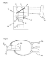
- FIG. 4 The effect of the device 10 on the image of the camera 24 is in FIG. 4 exemplified.
- the object area is shown, where the two subregions 34a-b lie next to one another in the longitudinal direction due to the tilting of the mirror elements 12, 14 and thus cover a greater width.
- the partial regions 34a-b coincide in the transverse direction due to suitable tilting of the mirror elements 34a-b, ie they merge directly into one another.
- the two partial areas 34a-b cover a widened field of vision.
- the subregions 34a-b are imaged one above the other, as on the right in FIG. 4 shown.
- a conventional image sensor 28 or a receiving optical system 26 having a rather square and conventional aspect ratio of, for example, 4/3 or 16/9 can be used and still a very wide image format can be achieved.
- subsequent image processing in the evaluation unit 30 or externally it is readily possible to join the two subregions 34a-b next to one another.
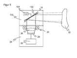
- FIG. 5 shows a sectional view of a camera 24 with another embodiment of a device 100 for deflecting and broadening the field of view of the camera 24.
- one mirror element 102 is provided, which, however, with the aid of a tilting unit 104 can be tilted. This is indicated by a respective representation of the mirror element 102 with a solid line and a dashed line.
- the mirror element 102 is thus tilted alternately or cyclically between two end positions, wherein the mirror element 102 is substantially in one position as the first mirror element 12 and in the other position as the second mirror element 14 of the embodiments according to Figure 1 to 3 ,
- the two sections 34a-b are then not recorded simultaneously, but alternately and with a time offset.
- the tilt in the transverse direction can be something from that according to FIGS. 1 to 3 deviate to compensate for a feed advance between two shots.
- the field of view is also broadened, but an offset of the subregions 34a-b remains in the lateral direction, ie in the conveying direction.
Landscapes
- Physics & Mathematics (AREA)
- General Physics & Mathematics (AREA)
- Engineering & Computer Science (AREA)
- Electromagnetism (AREA)
- Optics & Photonics (AREA)
- Health & Medical Sciences (AREA)
- General Health & Medical Sciences (AREA)
- Toxicology (AREA)
- Artificial Intelligence (AREA)
- Computer Vision & Pattern Recognition (AREA)
- Theoretical Computer Science (AREA)
- Multimedia (AREA)
- Signal Processing (AREA)
- Studio Devices (AREA)
Abstract
Description
- Die Erfindung betrifft eine Vorrichtung zum Umlenken und zur Verbreiterung des Sichtbereichs sowie ein entsprechendes Verfahren zum Aufnehmen eines Bildes aus einem verbreiterten Sichtbereich nach den Oberbegriffen von Anspruch 1, 11 und 12.
- In industriellen Anwendungen werden Kameras in vielfältiger Weise eingesetzt, um Objekteigenschaften automatisch zu erfassen, beispielsweise zur Inspektion oder Vermessung von Objekten. Dabei werden Bilder des Objekts aufgenommen und entsprechend der Aufgabe durch Bildverarbeitungsverfahren ausgewertet. Eine weitere Anwendung von Kameras ist das Lesen von Codes. Derartige kamerabasierte Codele-ser lösen die noch weit verbreiteten Barcodescanner zunehmend ab. Mit Hilfe eines Bildsensors werden Objekte mit den darauf befindlichen Codes aufgenommen, in den Bildern die Codebereiche identifiziert und dann dekodiert. Kamerabasierte Codeleser kommen problemlos auch mit anderen Codearten als eindimensionalen Strichcodes zurecht, die wie ein Matrixcode auch zweidimensional aufgebaut sind und mehr Informationen zur Verfügung stellen.
- Eine häufige Erfassungssituation ist die Montage der Kamera über einem Förderband, wo in Abhängigkeit der gewonnenen Objekteigenschaften weitere Bearbeitungsschritte eingeleitet werden. Solche Bearbeitungsschritte bestehen beispielsweise in der an das konkrete Objekt angepassten Weiterverarbeitung an einer Maschine, die auf geförderte Objekte einwirkt, oder in einer Veränderung des Objektstroms, indem bestimmte Objekte im Rahmen einer Qualitätskontrolle aus dem Objektstrom ausgeschleust werden oder der Objektstrom in mehrere Teilobjektströme sortiert wird.
- Der Erfassungsbereich einer herkömmlichen Kamera reicht oft nicht aus, um die volle gewünschte Breite insbesondere eines Förderbandes abzudecken. Als ein bekannter Ausweg werden mehrere Kameras nebeneinander montiert. Das löst zwar das Problem, erfordert aber einen erheblichem Mehraufwand für die mehreren Kameras sowie deren Montage und Koordinierung.
- Die
EP 2 624 042 A2 offenbart ein System zur Sichtfelderweiterung einer Kamera. Dazu wird ein Modul mit vier Spiegeln auf die Kamera aufgesetzt. Zwei äußere Spiegel fangen das Licht aus einem verbreiterten Sichtbereich ein und lenken es über innere Spiegel auf den Bildsensor um. Jedes Paar aus äußerem und innerem Spiegel nimmt einen Streifen des Sichtbereichs auf. Dabei sind die Spiegel so verkippt, dass die beiden Streifen im Objektbereich nebeneinander liegen, um eine größere Breite abzudecken, auf dem Bildsensor jedoch übereinander abgebildet werden. Das Modul ist in erster Linie für die Erfassung eines Sichtbereichs ausgelegt, der sich in Richtung der optischen Achse der Kamera befindet. Es wird aber auch eine in ganz ähnlicher Weise auf vier Spiegeln beruhende Variante vorgestellt, bei welcher der Sichtbereich in einem 90°-Versatz erfasst wird. Nachteilig an dieser Lösung ist die aufwändige Spiegelkonstruktion. - Es ist außerdem bekannt, einem Codeleser eine einfache Umlenkhaube mit einem um 45° verkippten Spiegel vorzuordnen, um eine Erfassung in einem 90°-Winkel zu ermöglichen. Damit wird aber auch ausschließlich die Umlenkung erreicht, eine Sichtfelderweiterung ist dabei nicht vorgesehen.
- Daher ist Aufgabe der Erfindung, den Sichtbereich einer Kamera zu verbreitern.
- Diese Aufgabe wird durch eine Vorrichtung zum Umlenken und zur Verbreiterung des Sichtbereichs sowie ein entsprechendes Verfahren zum Aufnehmen eines Bildes aus einem verbreiterten Sichtbereich nach Anspruch 1, 11 und 12 gelöst. Die Vorrichtung geht von einer Bildumlenkung aus, umfasst also einen Spiegel, um einen nicht gerade nach Vorn längs der optischen Achse der Kamera, sondern dagegen seitlich um einen Winkel versetzten Sichtbereich zu erfassen. Dazu ist der Spiegel in einer Längsrichtung verkippt.
- Nach einer ersten Alternative gemäß Anspruch 1 geht die Erfindung dann von dem Grundgedanken aus, zwei nebeneinander angeordnete, aber unterschiedlich verkippte Spiegelelemente zu verwenden. Der unterschiedliche Kippwinkel in Längsrichtung führt zu der gewünschten Sichtfeldverbreiterung, denn die beiden von den Spiegelelementen erfassten Teilbereiche ergänzen einander, um die geforderte Sichtfeldbreite zu erfassen. Das gelingt bis maximal zur doppelten Breite eines Teilbereichs, also der eigentlichen Sichtfeldbreite der Kamera, muss aber nicht optimal ausgenutzt werden, um einen Überlappungsbereich zu behalten. Durch zusätzliches Verkippen der Spiegelelemente in Querrichtung kann erreicht werden, dass die beiden Teilbereiche im Objektbereich direkt, d.h. ohne lateralen Versatz ineinander übergehen. Somit werden zwei im Objektbereich hintereinander liegende Teilbereiche in der Kamera übereinander erfasst.
- Nach einer zweiten Alternative gemäß Anspruch 11 ist nur ein Spiegelelement vorgesehen, das mit Hilfe einer Kippvorrichtung zwischen zwei Positionen wechselt. In diesen beiden Positionen erfüllt es genau die gleiche Funktion wie jeweils eines der beiden nebeneinander angeordneten Spiegelelemente nach der ersten Alternative. Es werden also zeitlich versetzt jeweils beispielsweise alternierend der linke Teil und der rechte Teil des Sichtbereichs erfasst. Prinzipiell genügt dafür ein Verkippen nur in Längsrichtung. Indem zusätzlich in der Querrichtung verkippt wird, gibt es aber bei geeigneter Wahl dieses Verkippens keinen lateralen Versatz zwischen linkem Teil und rechtem Teil.
- Die Erfindung hat den Vorteil, dass das Sichtfeld einer Kamera wesentlich verbreitert wird. Anschaulich gesprochen sorgt die erfindungsgemäße Vorrichtung dafür, dass aus einer Kamera mit einem üblichem Matrixsensor etwa im Format 4/3 oder 16/9 effektiv eine Kamera mit einem extremen Breitbildformat wird, beispielsweise um breitere Förderbänder über deren gesamte Breite abzudecken. Dabei ist die Vorrichtung mit ihren lediglich zwei Spiegeln sehr einfach aufgebaut und dadurch kostengünstig, wartungsarm und leicht zu justieren.
- Das erste Spiegelelement und das zweite Spiegelelement sind bevorzugt in Längsrichtung um 20°-70°, insbesondere 40°-50° oder im Wesentlichen 45° gegenüber der optischen Achse der Kamera verkippt. Die Kamera wird dementsprechend um den doppelten Winkel gegenüber dem zu erfassenden Sichtbereich verkippt, und diese Ausrichtung hängt von der Anwendung ab. Häufig möchte man die Kamera gerade um 90° verkippen, d.h. sie wird beispielsweise mit ihrer optischen Achse parallel zu einem Förderband ausgerichtet, und die Vorrichtung sorgt für eine 90°-Umlenkung. Dabei sind Abweichungen von einigen Grad möglich. Beide Spiegelelemente können ohnehin wegen der gegenseitigen Verkippung in Längsrichtung nicht um genau 45°, sondern nur um ungefähr 45° gegenüber der Kamera verkippt sein. Der Verkippungswinkel kann weiterhin von geometrischen Gegebenheiten der Aufnahmesituation, wie der Objektentfernung und der gewünschten Sichtfeldbreite, sowie von dem geforderten Überlappungsgrad der beiden von den Spiegelelementen aufgenommenen Teilbereiche abhängen.
- Das erste Spiegelelement und das zweite Spiegelelement sind vorzugsweise in Querrichtung um den gleichen Betrag, jedoch in unterschiedlicher Richtung verkippt. Dadurch sind die beiden Spiegelelemente in Querrichtung einander keilförmig zugewandt und nehmen lateral mittig gelegene Teilbereiche auf. Die Verkippung in Querrichtung muss diese Bedingungen nicht zwangsläufig erfüllen, aber das führt zu einer Art Schielen auf einen in Querrichtung versetzt gelegenen Sichtbereich.
- Das erste Spiegelelement und das zweite Spiegelelement bilden bevorzugt Spiegelflächen gleicher Geometrie. Die Spiegel sind damit optisch gleichwirkend, noch bevorzugter auch konstruktiv gleichartige Spiegel, die sich nur in der Verkippung unterscheiden. Dadurch werden auch gleichartige Teilbereiche aufgenommen, was die Weiterverarbeitung der Bilddaten des Sichtbereichs erleichtert.
- Die Vorrichtung weist bevorzugt ein drittes Spiegelelement auf, das gegenüber dem ersten Spiegelelement und dem zweiten Spiegelelement in Längsrichtung und in Querrichtung verkippt ist. Die Breite des Sichtfeldes wird dadurch nicht in zwei, sondern drei Abschnitte unterteilt, die im Objektbereich hintereinander und in der Kamera übereinander liegen. Das kann wahlweise genutzt werden, um ein noch breiteres Sichtfeld zu erfassen oder einen größeren Überlappungsbereich zu schaffen. Nach demselben Grundgedanken können auch noch mehr Spiegelelemente vorgesehen sein.
- Die Vorrichtung weist bevorzugt ein Gehäuse mit einem Verbindungselement auf, um lösbar als Haube mit einer Kamera verbunden zu werden. Dadurch kann eine Kamera nachträglich für ein breiteres Sichtfeld umgerüstet werden. Alternativ zu einer lösbaren Verbindung kann die Vorrichtung auch schon ab Werk fest mit der Kamera verbunden werden, oder das Gehäuse der Vorrichtung ist sogar Teil eines Kameragehäuses.
- In bevorzugter Weiterbildung ist eine Kamera vorgesehen, die mit einer erfindungsgemäßen Vorrichtung zur Sichtfeldverbreiterung ausgestattet ist.
- Eine solche Kamera weist bevorzugt eine Beleuchtungseinrichtung auf, deren Licht über die Spiegelelemente in den Sichtbereich umgelenkt wird, um den Sichtbereich auszuleuchten. Die Beleuchtung nutzt also die gleichen Spiegelelemente wie das Empfangslicht. Dadurch wird auch für eine aktiv beleuchtete Kamera der Sichtbereich verbreitert, ohne dass an der Beleuchtung etwas verändert werden müsste. Die Vorrichtung sorgt mit der Sichtbereichsverbreiterung automatisch auch für dessen Ausleuchtung.
- Die Kamera weist bevorzugt eine Auswertungseinheit auf, um einen über das erste Spiegelelement aufgenommenen Teilbereich des Sichtbereichs und einen über das zweite Spiegelelement aufgenommenen Teilbereich des Sichtbereichs zu einem gemeinsamen Bild des verbreiterten Sichtfeldes zu verbinden. Die auf dem Bildsensor der Kamera übereinander angeordneten Teilbilder werden dadurch zu einem gemeinsamen Bild verbunden. Die Kamera wird dadurch zu einer Kamera mit einem breiteren Bildformat, und der Anwender muss sich nach geeigneter Anfangsjustierung der Spiegelelemente um die Teilbereiche gar nicht weiter kümmern.
- Die Kamera ist bevorzugt als kamerabasierter Codeleser mit einer Decodiereinheit zum Identifizieren von Codebereichen und zum Auslesen von Codeinhalten ausgebildet. Aufgrund der Sichtbereichsverbreiterung deckt dieser Codeleser ein breiteres Lesefeld ab, insbesondere ein breiteres Förderband
- Das erfindungsgemäße Verfahren kann auf ähnliche Weise weitergebildet werden und zeigt dabei ähnliche Vorteile. Derartige vorteilhafte Merkmale sind beispielhaft, aber nicht abschließend in den sich an die unabhängigen Ansprüche anschließenden Unteransprüchen beschrieben.
- Die Erfindung wird nachstehend auch hinsichtlich weiterer Merkmale und Vorteile beispielhaft anhand von Ausführungsformen und unter Bezug auf die beigefügte Zeichnung näher erläutert. Die Abbildungen der Zeichnung zeigen in:
- Fig. 1
- eine dreidimensionale Ansicht einer Vorrichtung zum Umlenken und zur Verbreiterung des Sichtbereichs einer Kamera;
- Fig. 2
- eine dreidimensionale Ansicht ähnlich
Figur 1 , jedoch mit Beleuchtung; - Fig. 3
- eine schematische Schnittdarstellung einer Kamera mit einer Vorrichtung gemäß
Figur 2 ; - Fig. 4
- ein beispielhafter verbreiterter Sichtbereich einer Kamera und dessen Abbildung in der Kamera; und
- Fig. 5
- eine schematische Schnittdarstellung einer Kamera mit einer weiteren Ausführungsform einer Vorrichtung zum Umlenken und zur Verbreiterung des Sichtbereichs.
-
Figur 1 zeigt eine dreidimensionale Ansicht einer Bildumlenkhaube beziehungsweise Vorrichtung 10 zum Umlenken und zur Verbreiterung des Sichtbereichs einer Kamera. Die Vorrichtung 10 weist nebeneinanderliegend ein erstes Spiegelelement 12 und ein zweites Spiegelelement 14 auf. Die beiden Spiegelelemente 12, 14 sind an einer Welle 16 montiert, die wiederum in einem Gehäuse 18 gehaltert ist. Das Gehäuse 18 dient zugleich der mechanischen Stabilität und als optische Abschirmung. Im unteren Teil des Gehäuses 18 ist ein Verbindungselement 20 vorgesehen, um die Vorrichtung 10 mit einer Kamera zu verbinden, so dass deren Objektiv mit seiner optischen Achse auf die Spiegelelemente 12, 14 ausgerichtet ist. Die optische Achse verläuft in der Perspektive derFigur 1 von unten nach oben, wobei die Spiegelelemente 12, 14 für eine Bildumlenkung von etwa 90° sorgen, so dass der effektive Sichtbereich der Kamera oberhalb der Papierebene liegt. - Die Spiegelelemente 12, 14 können unabhängig voneinander in zwei Achsen verkippt werden. Deutlich in
Figur 1 zu erkennen ist eine Verkippung in einer Längsrichtung. Der Kippwinkel beträgt in etwa 45°, um die gewünschte 90°-Bildumlenkung zu erreichen. Der Kippwinkel weicht jedoch von genau 45° ab, denn beide Spiegelelemente 12, 14 sind auch gegeneinander in Längsrichtung verkippt. Dadurch sind die Spiegelelemente 12, 14 auf Teilbereiche im Objektbereich ausgerichtet, die in der Perspektive derFigur 1 in unterschiedlichen Höhen liegen. In einer tatsächlichen Anwendung würde man die Vorrichtung 10 üblicherweise so ausrichten, dass die Höhenrichtung derFigur 1 einer zu erfassenden Breite beispielsweise eines Förderbandes entspricht. Die beiden Teilbereiche ergänzen einander und decken somit eine größere Breite ab. Der unterschiedliche Kippwinkel in Längsrichtung der beiden Spiegelelemente 12, 14 wird vorzugsweise in Abhängigkeit von einem Objektabstand auf die gewünschte zu erfassende Breite justiert. Ein gewisser Überlapp der Teilbereiche ist möglich und beispielsweise für das Zusammenfügen eines gemeinsamen Bildes (Stitching) sogar erwünscht. - Allerdings hätten die beiden Teilbereiche dann noch einen lateralen gegenseitigen Versatz. Deshalb sind die Spiegelelemente 12, 14 auch in einer Querrichtung senkrecht zu der Längsrichtung verkippt. Die beiden Spiegelelemente 12, 14 sind dazu zueinander geneigt und bilden einen Keil. Allerdings ist der Keilwinkel sehr klein und deshalb in
Figur 1 kaum zu erkennen. Durch das Verkippen in Querrichtung werden die Teilbereiche so justiert, dass sie auf einer gemeinsamen Achse liegen, die entsprechenden Teilbilder also über die Breite des Sichtbereichs gerade ineinander übergehen. Damit wird ein kontinuierlicher Bereich quer zur Förderrichtung abgebildet. -
Figur 2 zeigt eine dreidimensionale Ansicht einer weiteren Ausführungsform der Vorrichtung 10. Wie in der gesamten Beschreibung bezeichnen dabei gleiche Bezugszeichen die gleichen Merkmale. Abgesehen von der etwas anderen Perspektive unterscheidet sich diese Darstellung vonFigur 1 dadurch, dass zusätzlich eine Beleuchtungseinrichtung 22 vorgesehen ist, hier beispielhaft in Form von ringförmig um eine Öffnung für das Objektiv einer Kamera vorgesehenen LEDs. Das Licht dieser Beleuchtungseinrichtung 22 wird von der Vorrichtung 10 in genau der gleichen Weise zu dem Sichtbereich geleitet, wie auf dem umgekehrten Lichtweg der Sichtbereich der Kamera umgelenkt und verbreitert wird. -
Figur 3 zeigt in einer schematischen Schnittansicht eine Kamera 24 mit einer Vorrichtung 10 zur Sichtfeldverbreiterung. Die Kamera 24 weist die Beleuchtungseinrichtung 22, ein Objektiv beziehungsweise eine Empfangsoptik 26, einen Bildsensor 28 mit matrixartig angeordneten lichtempfindlichen Empfangselementen und eine Steuer- und Auswertungseinheit 30 auf. Die Kamera 24 ist insbesondere ein kamerabasierter Codeleser, deren Auswertungseinheit 30 in aufgenommenen Bilddaten Codebereiche identifizieren und die Codeinhalte auslesen kann. Die Auswertungseinheit 30 ist zudem vorzugsweise in der Lage, mehrere aufgenommene Teilbereiche oder Bildstreifen zu einem gemeinsamen Bild zusammenzufügen. - Die Kamera 24 nimmt über die Spiegelelemente 12, 14 ein Objekt 32 in zwei Teilbereichen auf, wobei die jeweiligen Lichtwege über die beiden Spiegelelemente 12, 14 durch unterschiedliche Strichbreiten angedeutet sind. Der Versatz der entstehenden Teilbereiche auf dem Objekt 32 kann kleiner oder größer sein als dargestellt, dies hängt vom gegenseitigen Kippwinkel der Spiegelelemente 12, 14 und dem Abstand zu dem Objekt 32 ab. Die zusätzliche Verkippung der Spiegelelemente 12,14 ist in
Figur 3 aufgrund der Schnittansicht nicht erkennbar. Sie führt dazu, dass die beiden Teilbereiche auf dem Objekt 32 in lateraler Richtung übereinstimmen, also inFigur 3 längs einer Senkrechten zur Papierebene. - Der Effekt der Vorrichtung 10 auf das Bild der Kamera 24 ist in
Figur 4 beispielhaft illustriert. Links ist der Objektbereich dargestellt, wo die beiden Teilbereiche 34a-b aufgrund der Verkippung der Spiegelelemente 12, 14 in Längsrichtung zueinander versetzt nebeneinander liegen und somit eine größere Breite abdecken. In lateraler Richtung dagegen stimmen die Teilbereiche 34a-b aufgrund geeigneter Verkippung der Spiegelelemente 34a-b in Querrichtung überein, gehen also direkt ineinander über. In Summe decken die beiden Teilbereiche 34a-b ein verbreitertes Sichtfeld ab. - Im Bildbereich beziehungsweise auf dem Bildsensor 28 dagegen werden die Teilbereiche 34a-b übereinander abgebildet, wie rechts in
Figur 4 dargestellt. Damit kann ein herkömmlicher Bildsensor 28 beziehungsweise eine Empfangsoptik 26 mit eher quadratischem und üblichen Bildverhältnis (aspect ratio) von beispielsweise 4/3 oder 16/9 eingesetzt werden und dennoch ein sehr breites Bildformat erzielt werden. Durch nachgelagerte Bildbearbeitung in der Auswertungseinheit 30 oder extern ist ohne weiteres möglich, die beiden Teilbereiche 34a-b nebeneinander zusammenzufügen. Andererseits ist auch denkbar, die in beiden Teilbereichen 34a-b abgebildeten Überlappungsbereiche so groß zu lassen, dass ein aufgenommener Code bekannter Größe stets vollständig in zumindest einem Teilbereich 34a-b erfasst ist. Dann ist ein Zusammenfügen zu einem homogenen Bild zur Decodierung gar nicht erforderlich. -
Figur 5 zeigt eine Schnittansicht einer Kamera 24 mit einer weiteren Ausführungsform einer Vorrichtung 100 zum Umlenken und zur Verbreiterung des Sichtbereichs der Kamera 24. Im Gegensatz zu den bisher beschriebenen Ausführungsformen ist hier nur ein Spiegelelement 102 vorgesehen, das allerdings mit Hilfe einer Kippeinheit 104 verkippt werden kann. Das ist durch jeweils eine Darstellung des Spiegelelements 102 mit durchgezogener und mit gestrichelter Linie angedeutet. Das Spiegelelement 102 wird folglich alternierend oder zyklisch zwischen zwei Endpositionen verkippt, wobei das Spiegelelement 102 im Wesentlichen in der einen Position so steht wie das erste Spiegelelement 12 und in der anderen Position wie das zweite Spiegelelement 14 der Ausführungsformen gemäßFigur 1 bis 3 . Die beiden Teilbereiche 34a-b werden dann nicht gleichzeitig, sondern abwechselnd und zeitlich versetzt aufgenommen. Die Verkippung in Querrichtung kann etwas von derjenigen gemäßFiguren 1 bis 3 abweichen, um einen Fördervorschub zwischen zwei Aufnahmen auszugleichen. Es ist prinzipiell auch denkbar, das Spiegelelement 102 nur in Längsrichtung und nicht in Querrichtung zu verkippen. Dadurch wird das Sichtfeld ebenfalls verbreitert, jedoch verbleibt ein Versatz der Teilbereiche 34a-b in lateraler Richtung, also in Förderrichtung.
Claims (12)
- Vorrichtung (10) zum Umlenken und zur Verbreiterung des Sichtbereichs einer Kamera (24), wobei die Vorrichtung (10) ein erstes Spiegelelement (12) aufweist, das gegenüber der optischen Achse der Kamera (24) in einer Längsrichtung verkippt ist, um der Kamera (24) Licht aus einem bezüglich der optischen Achse seitlich gelegenen Sichtbereich zuzuleiten,
dadurch gekennzeichnet,
dass das erste Spiegelelement (12) zusätzlich in einer Querrichtung senkrecht zu der Längsrichtung verkippt ist und dass die Vorrichtung ein zweites Spiegelelement (14) neben dem ersten Spiegelelement (12) aufweist, das in Längsrichtung und in Querrichtung gegenüber dem ersten Spiegelelement (12) verkippt ist. - Vorrichtung (10) nach Anspruch 1,
wobei das erste Spiegelelement (12) und das zweite Spiegelelement (14) in Längsrichtung um 20°-70°, insbesondere 40°-50° oder im Wesentlichen 45° gegenüber der optischen Achse der Kamera (24) verkippt sind. - Vorrichtung (10) nach Anspruch 1 oder 2,
wobei das erste Spiegelelement (12) und das zweite Spiegelelement (14) in Querrichtung um den gleichen Betrag, jedoch in unterschiedlicher Richtung verkippt sind. - Vorrichtung (10) nach einem der vorhergehenden Ansprüche,
wobei das erste Spiegelelement (12) und das zweite Spiegelelement (14) Spiegelflächen gleicher Geometrie bilden. - Vorrichtung (10) nach einem der vorhergehenden Ansprüche,
wobei die Vorrichtung (10) ein drittes Spiegelelement aufweist, das gegenüber dem ersten Spiegelelement (12) und dem zweiten Spiegelelement (14) in Längsrichtung und in Querrichtung verkippt ist. - Vorrichtung (10) nach einem der vorhergehenden Ansprüche,
wobei die Vorrichtung (10) ein Gehäuse (18) mit einem Verbindungselement (20) aufweist, um lösbar als Haube mit einer Kamera (24) verbunden zu werden. - Kamera (24) mit einer Vorrichtung (10) nach einem der vorhergehenden Ansprüche.
- Kamera (10) nach Anspruch 7,
die eine Beleuchtungseinrichtung (22) aufweist, deren Licht über die Spiegelelemente (12, 14) in den Sichtbereich umgelenkt wird, um den Sichtbereich auszuleuchten. - Kamera (10) nach Anspruch 7 oder 8,
die eine Auswertungseinheit (30) aufweist, um einen über das erste Spiegelelement (12) aufgenommenen Teilbereich (34a) des Sichtbereichs und einen über das zweite Spiegelelement (14) aufgenommenen Teilbereich (34b) des Sichtbereichs zu einem gemeinsamen Bild des verbreiterten Sichtfeldes zu verbinden. - Kamera (10) nach einem der Ansprüche 7 bis 9,
die als kamerabasierter Codeleser mit einer Decodiereinheit (30) zum Identifizieren von Codebereichen und zum Auslesen von Codeinhalten ausgebildet ist. - Vorrichtung (100) zum Umlenken und zur Verbreiterung des Sichtbereichs einer Kamera (24), wobei die Vorrichtung (100) ein Spiegelelement (102) aufweist, das in einer ersten Position gegenüber der optischen Achse der Kamera (24) in einer Längsrichtung verkippt ist, um der Kamera (24) Licht aus einem bezüglich der optischen Achse seitlich gelegenen Sichtbereich zuzuleiten,
dadurch gekennzeichnet,
dass das Spiegelelement (102) in der ersten Position zusätzlich in einer Querrichtung senkrecht zu der Längsrichtung verkippt ist und dass eine Kippeinheit (104) vorgesehen ist, um das Spiegelelement (102) alternierend in die erste Position und in eine zweite Position zu verkippen, in der das Spiegelelement (102) in Längsrichtung und in Querrichtung gegenüber der ersten Position verkippt ist. - Verfahren zum Aufnehmen eines Bildes aus einem verbreiterten Sichtbereich mit einer Kamera (24), bei dem Licht aus einem bezüglich der optischen Achse seitlich gelegenen Sichtbereich über ein Spiegelelement (12, 102) der Kamera (24) zugeleitet wird, das gegenüber der optischen Achse der Kamera (24) in einer Längsrichtung verkippt wird,
dadurch gekennzeichnet,
dass das Spiegelelement (12, 102) auch in einer Querrichtung senkrecht zu der Längsrichtung verkippt wird, und dass das Bild in zwei Teilbereichen (34a-b) gleichzeitig über das Spiegelelement (12) und ein weiteres Spiegelelement (14), das gegenüber dem Spiegelelement (12) in Längsrichtung und in Querrichtung verkippt ist, oder nacheinander über das Spiegelelement (102) in zwei verschiedenen Positionen aufgenommen wird, in denen das Spiegelelement (102) in Längsrichtung und in Querrichtung unterschiedlich verkippt ist.
Priority Applications (4)
| Application Number | Priority Date | Filing Date | Title |
|---|---|---|---|
| EP13189372.9A EP2863253B1 (de) | 2013-10-18 | 2013-10-18 | Vorrichtung zum Umlenken und zur Verbreiterung des Sichtbereichs |
| ES13189372.9T ES2550132T3 (es) | 2013-10-18 | 2013-10-18 | Dispositivo para la desviación y para la ampliación del campo de visión |
| DK13189372.9T DK2863253T3 (da) | 2013-10-18 | 2013-10-18 | Device for deviating and for enlarging the field of view |
| US14/505,638 US9141840B2 (en) | 2013-10-18 | 2014-10-03 | Apparatus for deflecting and for widening a visible range |
Applications Claiming Priority (1)
| Application Number | Priority Date | Filing Date | Title |
|---|---|---|---|
| EP13189372.9A EP2863253B1 (de) | 2013-10-18 | 2013-10-18 | Vorrichtung zum Umlenken und zur Verbreiterung des Sichtbereichs |
Publications (2)
| Publication Number | Publication Date |
|---|---|
| EP2863253A1 true EP2863253A1 (de) | 2015-04-22 |
| EP2863253B1 EP2863253B1 (de) | 2015-08-19 |
Family
ID=49385157
Family Applications (1)
| Application Number | Title | Priority Date | Filing Date |
|---|---|---|---|
| EP13189372.9A Active EP2863253B1 (de) | 2013-10-18 | 2013-10-18 | Vorrichtung zum Umlenken und zur Verbreiterung des Sichtbereichs |
Country Status (4)
| Country | Link |
|---|---|
| US (1) | US9141840B2 (de) |
| EP (1) | EP2863253B1 (de) |
| DK (1) | DK2863253T3 (de) |
| ES (1) | ES2550132T3 (de) |
Cited By (3)
| Publication number | Priority date | Publication date | Assignee | Title |
|---|---|---|---|---|
| DE202017100478U1 (de) | 2017-01-30 | 2017-03-14 | Sick Ag | Kamera zur Aufnahme von Bilddaten aus einem Erfassungsbereich |
| EP3196688A1 (de) * | 2016-01-22 | 2017-07-26 | Siemens Aktiengesellschaft | Optische objekterfassungsvorrichtung, optischer sensor und aufsatz für einen optischen sensor |
| EP3290987A1 (de) * | 2016-09-01 | 2018-03-07 | Funai Electric Co., Ltd. | Scanner spiegel |
Families Citing this family (4)
| Publication number | Priority date | Publication date | Assignee | Title |
|---|---|---|---|---|
| US9027838B2 (en) | 2012-02-06 | 2015-05-12 | Cognex Corporation | System and method for expansion of field of view in a vision system |
| US11966810B2 (en) | 2012-02-06 | 2024-04-23 | Cognex Corporation | System and method for expansion of field of view in a vision system |
| US9892298B2 (en) | 2012-02-06 | 2018-02-13 | Cognex Corporation | System and method for expansion of field of view in a vision system |
| KR102813751B1 (ko) * | 2024-02-14 | 2025-05-28 | (주)하나기술 | 이차전지 셀 바코드 리딩장치 |
Citations (5)
| Publication number | Priority date | Publication date | Assignee | Title |
|---|---|---|---|---|
| JPH08171151A (ja) * | 1994-12-16 | 1996-07-02 | Olympus Optical Co Ltd | ステレオカメラ |
| US5708470A (en) * | 1996-06-10 | 1998-01-13 | Condor Systems, Inc. | Optical monitoring system apparatus |
| JP2004070302A (ja) * | 2002-06-12 | 2004-03-04 | Eriko Shimizu | 立体画面構成方式 |
| US20120261473A1 (en) * | 2011-03-17 | 2012-10-18 | United States Postal Service | Systems, methods, and apparatus for overhead scanning of images in a manual distribution environment |
| EP2624042A2 (de) | 2012-02-06 | 2013-08-07 | Cognex Corporation | System und Verfahren zur Erweiterung des Sichtfeldes in einem Sichtsystem |
Family Cites Families (6)
| Publication number | Priority date | Publication date | Assignee | Title |
|---|---|---|---|---|
| CA1073715A (en) * | 1977-10-06 | 1980-03-18 | Northern Telecom Limited | Optical system for multiple imaging of a linear object |
| US5870219A (en) * | 1997-01-20 | 1999-02-09 | Geo. Labs, Inc. | Ultra compact scanning system for a wide range of speeds, angles and field depth |
| JPH08171152A (ja) | 1994-12-16 | 1996-07-02 | Olympus Optical Co Ltd | 撮像装置 |
| US8149490B2 (en) * | 2006-08-18 | 2012-04-03 | Nippon Telegraph And Telephone Corporation | Optical switch, optical switch control method and communication system |
| US20090127341A1 (en) * | 2007-11-19 | 2009-05-21 | Xiangyang Feng | Bar-code reading tool |
| US8608076B2 (en) * | 2008-02-12 | 2013-12-17 | Datalogic ADC, Inc. | Monolithic mirror structure for use in a multi-perspective optical code reader |
-
2013
- 2013-10-18 ES ES13189372.9T patent/ES2550132T3/es active Active
- 2013-10-18 EP EP13189372.9A patent/EP2863253B1/de active Active
- 2013-10-18 DK DK13189372.9T patent/DK2863253T3/da active
-
2014
- 2014-10-03 US US14/505,638 patent/US9141840B2/en active Active
Patent Citations (5)
| Publication number | Priority date | Publication date | Assignee | Title |
|---|---|---|---|---|
| JPH08171151A (ja) * | 1994-12-16 | 1996-07-02 | Olympus Optical Co Ltd | ステレオカメラ |
| US5708470A (en) * | 1996-06-10 | 1998-01-13 | Condor Systems, Inc. | Optical monitoring system apparatus |
| JP2004070302A (ja) * | 2002-06-12 | 2004-03-04 | Eriko Shimizu | 立体画面構成方式 |
| US20120261473A1 (en) * | 2011-03-17 | 2012-10-18 | United States Postal Service | Systems, methods, and apparatus for overhead scanning of images in a manual distribution environment |
| EP2624042A2 (de) | 2012-02-06 | 2013-08-07 | Cognex Corporation | System und Verfahren zur Erweiterung des Sichtfeldes in einem Sichtsystem |
Cited By (6)
| Publication number | Priority date | Publication date | Assignee | Title |
|---|---|---|---|---|
| EP3196688A1 (de) * | 2016-01-22 | 2017-07-26 | Siemens Aktiengesellschaft | Optische objekterfassungsvorrichtung, optischer sensor und aufsatz für einen optischen sensor |
| EP3290987A1 (de) * | 2016-09-01 | 2018-03-07 | Funai Electric Co., Ltd. | Scanner spiegel |
| CN107797273A (zh) * | 2016-09-01 | 2018-03-13 | 船井电机株式会社 | 扫描镜 |
| US10345579B2 (en) | 2016-09-01 | 2019-07-09 | Funai Electric Co., Ltd. | Scanner mirror |
| CN107797273B (zh) * | 2016-09-01 | 2020-05-19 | 船井电机株式会社 | 扫描镜 |
| DE202017100478U1 (de) | 2017-01-30 | 2017-03-14 | Sick Ag | Kamera zur Aufnahme von Bilddaten aus einem Erfassungsbereich |
Also Published As
| Publication number | Publication date |
|---|---|
| US20150108218A1 (en) | 2015-04-23 |
| ES2550132T3 (es) | 2015-11-04 |
| DK2863253T3 (da) | 2015-09-14 |
| US9141840B2 (en) | 2015-09-22 |
| EP2863253B1 (de) | 2015-08-19 |
Similar Documents
| Publication | Publication Date | Title |
|---|---|---|
| EP2937810B1 (de) | Kamera und Verfahren zur Erfassung eines bewegten Stroms von Objekten | |
| EP2863253B1 (de) | Vorrichtung zum Umlenken und zur Verbreiterung des Sichtbereichs | |
| DE202013009198U1 (de) | Vorrichtung zum Umlenken und zur Verbreiterung des Sichtbereichs | |
| EP2693364B1 (de) | Kamerasystem und Verfahren zur Erfassung eines Stromes von Objekten | |
| EP2546776A1 (de) | Kamerabasierter Codeleser und Verfahren zu dessen justierter Herstellung | |
| EP3167605B1 (de) | Vorrichtung und verfahren zur erfassung eines objektbereichs | |
| DE102013110615B3 (de) | 3D-Kamera nach dem Stereoskopieprinzip und Verfahren zum Erfassen von Tiefenkarten | |
| EP2693363A1 (de) | Kamerasystem und Verfahren zur Erfassung eines Stromes von Objekten | |
| EP3383026A1 (de) | Kamera und verfahren zur erfassung von relativ zu der kamera in einer förderrichtung bewegten objekten | |
| DE102018123574A1 (de) | Bildgebungvorrichtungen mit zielsystemen | |
| DE112015006637T5 (de) | Bauteilmontagevorrichtung und Verfahren zur Bauteilmontagebestimmung für eine Bauteilmontagevorrichtung | |
| DE102014114506A1 (de) | Kamera zur Montage an einer Fördereinrichtung und Verfahren zur Inspektion oder Identifikation | |
| EP3687155B1 (de) | Modulare kameravorrichtung und verfahren zur optischen erfassung | |
| EP2202075A2 (de) | Verfahren und Vorrichtung zur Druckbeobachtung mittels einer Zeilenkamera | |
| DE102017119282B4 (de) | Optische Abbildungsvorrichtungen und -verfahren | |
| DE102019102783A1 (de) | Ausrichtziel und Verfahren zum Ausrichten einer Kamera | |
| EP4030234B1 (de) | Kameravorrichtung und verfahren zur erfassung eines objekts | |
| EP2474956B1 (de) | Transporteinheit und Verfahren zum Betrieb derselben | |
| EP3822198B1 (de) | Stückguterfassungsanordnung | |
| WO2012045805A1 (de) | Verfahren und einrichtung zum erfassen und bedrucken von dokumenten | |
| DE202014101927U1 (de) | Kamera zur Erfassung eines bewegten Stroms von Objekten | |
| EP1130533B1 (de) | Optischer Abtaster | |
| DE202009017346U1 (de) | Optikvorrichtung für einen optoelektronischen Sensor | |
| DE102023135245B3 (de) | Kamerasystem für eine Etikettenerkennungsvorrichtung | |
| EP4351159B1 (de) | Bildsensor |
Legal Events
| Date | Code | Title | Description |
|---|---|---|---|
| PUAI | Public reference made under article 153(3) epc to a published international application that has entered the european phase |
Free format text: ORIGINAL CODE: 0009012 |
|
| 17P | Request for examination filed |
Effective date: 20140310 |
|
| AK | Designated contracting states |
Kind code of ref document: A1 Designated state(s): AL AT BE BG CH CY CZ DE DK EE ES FI FR GB GR HR HU IE IS IT LI LT LU LV MC MK MT NL NO PL PT RO RS SE SI SK SM TR |
|
| AX | Request for extension of the european patent |
Extension state: BA ME |
|
| GRAP | Despatch of communication of intention to grant a patent |
Free format text: ORIGINAL CODE: EPIDOSNIGR1 |
|
| INTG | Intention to grant announced |
Effective date: 20150520 |
|
| GRAS | Grant fee paid |
Free format text: ORIGINAL CODE: EPIDOSNIGR3 |
|
| GRAA | (expected) grant |
Free format text: ORIGINAL CODE: 0009210 |
|
| AK | Designated contracting states |
Kind code of ref document: B1 Designated state(s): AL AT BE BG CH CY CZ DE DK EE ES FI FR GB GR HR HU IE IS IT LI LT LU LV MC MK MT NL NO PL PT RO RS SE SI SK SM TR |
|
| REG | Reference to a national code |
Ref country code: GB Ref legal event code: FG4D Free format text: NOT ENGLISH |
|
| REG | Reference to a national code |
Ref country code: CH Ref legal event code: EP |
|
| REG | Reference to a national code |
Ref country code: IE Ref legal event code: FG4D Free format text: LANGUAGE OF EP DOCUMENT: GERMAN |
|
| REG | Reference to a national code |
Ref country code: DK Ref legal event code: T3 Effective date: 20150910 |
|
| REG | Reference to a national code |
Ref country code: AT Ref legal event code: REF Ref document number: 744216 Country of ref document: AT Kind code of ref document: T Effective date: 20150915 |
|
| REG | Reference to a national code |
Ref country code: DE Ref legal event code: R096 Ref document number: 502013001041 Country of ref document: DE |
|
| REG | Reference to a national code |
Ref country code: SE Ref legal event code: TRGR |
|
| REG | Reference to a national code |
Ref country code: FR Ref legal event code: PLFP Year of fee payment: 3 |
|
| REG | Reference to a national code |
Ref country code: ES Ref legal event code: FG2A Ref document number: 2550132 Country of ref document: ES Kind code of ref document: T3 Effective date: 20151104 |
|
| REG | Reference to a national code |
Ref country code: NL Ref legal event code: FP |
|
| REG | Reference to a national code |
Ref country code: LT Ref legal event code: MG4D |
|
| PG25 | Lapsed in a contracting state [announced via postgrant information from national office to epo] |
Ref country code: LV Free format text: LAPSE BECAUSE OF FAILURE TO SUBMIT A TRANSLATION OF THE DESCRIPTION OR TO PAY THE FEE WITHIN THE PRESCRIBED TIME-LIMIT Effective date: 20150819 Ref country code: FI Free format text: LAPSE BECAUSE OF FAILURE TO SUBMIT A TRANSLATION OF THE DESCRIPTION OR TO PAY THE FEE WITHIN THE PRESCRIBED TIME-LIMIT Effective date: 20150819 Ref country code: GR Free format text: LAPSE BECAUSE OF FAILURE TO SUBMIT A TRANSLATION OF THE DESCRIPTION OR TO PAY THE FEE WITHIN THE PRESCRIBED TIME-LIMIT Effective date: 20151120 Ref country code: NO Free format text: LAPSE BECAUSE OF FAILURE TO SUBMIT A TRANSLATION OF THE DESCRIPTION OR TO PAY THE FEE WITHIN THE PRESCRIBED TIME-LIMIT Effective date: 20151119 Ref country code: LT Free format text: LAPSE BECAUSE OF FAILURE TO SUBMIT A TRANSLATION OF THE DESCRIPTION OR TO PAY THE FEE WITHIN THE PRESCRIBED TIME-LIMIT Effective date: 20150819 |
|
| PG25 | Lapsed in a contracting state [announced via postgrant information from national office to epo] |
Ref country code: IS Free format text: LAPSE BECAUSE OF FAILURE TO SUBMIT A TRANSLATION OF THE DESCRIPTION OR TO PAY THE FEE WITHIN THE PRESCRIBED TIME-LIMIT Effective date: 20151219 Ref country code: PL Free format text: LAPSE BECAUSE OF FAILURE TO SUBMIT A TRANSLATION OF THE DESCRIPTION OR TO PAY THE FEE WITHIN THE PRESCRIBED TIME-LIMIT Effective date: 20150819 Ref country code: PT Free format text: LAPSE BECAUSE OF FAILURE TO SUBMIT A TRANSLATION OF THE DESCRIPTION OR TO PAY THE FEE WITHIN THE PRESCRIBED TIME-LIMIT Effective date: 20151221 Ref country code: RS Free format text: LAPSE BECAUSE OF FAILURE TO SUBMIT A TRANSLATION OF THE DESCRIPTION OR TO PAY THE FEE WITHIN THE PRESCRIBED TIME-LIMIT Effective date: 20150819 |
|
| PG25 | Lapsed in a contracting state [announced via postgrant information from national office to epo] |
Ref country code: EE Free format text: LAPSE BECAUSE OF FAILURE TO SUBMIT A TRANSLATION OF THE DESCRIPTION OR TO PAY THE FEE WITHIN THE PRESCRIBED TIME-LIMIT Effective date: 20150819 Ref country code: SK Free format text: LAPSE BECAUSE OF FAILURE TO SUBMIT A TRANSLATION OF THE DESCRIPTION OR TO PAY THE FEE WITHIN THE PRESCRIBED TIME-LIMIT Effective date: 20150819 |
|
| REG | Reference to a national code |
Ref country code: DE Ref legal event code: R097 Ref document number: 502013001041 Country of ref document: DE |
|
| PG25 | Lapsed in a contracting state [announced via postgrant information from national office to epo] |
Ref country code: LU Free format text: LAPSE BECAUSE OF FAILURE TO SUBMIT A TRANSLATION OF THE DESCRIPTION OR TO PAY THE FEE WITHIN THE PRESCRIBED TIME-LIMIT Effective date: 20151018 Ref country code: RO Free format text: LAPSE BECAUSE OF FAILURE TO SUBMIT A TRANSLATION OF THE DESCRIPTION OR TO PAY THE FEE WITHIN THE PRESCRIBED TIME-LIMIT Effective date: 20150819 |
|
| PLBE | No opposition filed within time limit |
Free format text: ORIGINAL CODE: 0009261 |
|
| STAA | Information on the status of an ep patent application or granted ep patent |
Free format text: STATUS: NO OPPOSITION FILED WITHIN TIME LIMIT |
|
| PG25 | Lapsed in a contracting state [announced via postgrant information from national office to epo] |
Ref country code: MC Free format text: LAPSE BECAUSE OF FAILURE TO SUBMIT A TRANSLATION OF THE DESCRIPTION OR TO PAY THE FEE WITHIN THE PRESCRIBED TIME-LIMIT Effective date: 20150819 |
|
| 26N | No opposition filed |
Effective date: 20160520 |
|
| REG | Reference to a national code |
Ref country code: IE Ref legal event code: MM4A |
|
| PG25 | Lapsed in a contracting state [announced via postgrant information from national office to epo] |
Ref country code: SI Free format text: LAPSE BECAUSE OF FAILURE TO SUBMIT A TRANSLATION OF THE DESCRIPTION OR TO PAY THE FEE WITHIN THE PRESCRIBED TIME-LIMIT Effective date: 20150819 |
|
| REG | Reference to a national code |
Ref country code: FR Ref legal event code: PLFP Year of fee payment: 4 |
|
| PG25 | Lapsed in a contracting state [announced via postgrant information from national office to epo] |
Ref country code: IE Free format text: LAPSE BECAUSE OF NON-PAYMENT OF DUE FEES Effective date: 20151018 |
|
| PG25 | Lapsed in a contracting state [announced via postgrant information from national office to epo] |
Ref country code: BG Free format text: LAPSE BECAUSE OF FAILURE TO SUBMIT A TRANSLATION OF THE DESCRIPTION OR TO PAY THE FEE WITHIN THE PRESCRIBED TIME-LIMIT Effective date: 20150819 |
|
| PG25 | Lapsed in a contracting state [announced via postgrant information from national office to epo] |
Ref country code: CY Free format text: LAPSE BECAUSE OF FAILURE TO SUBMIT A TRANSLATION OF THE DESCRIPTION OR TO PAY THE FEE WITHIN THE PRESCRIBED TIME-LIMIT Effective date: 20150819 Ref country code: HU Free format text: LAPSE BECAUSE OF FAILURE TO SUBMIT A TRANSLATION OF THE DESCRIPTION OR TO PAY THE FEE WITHIN THE PRESCRIBED TIME-LIMIT; INVALID AB INITIO Effective date: 20131018 |
|
| PG25 | Lapsed in a contracting state [announced via postgrant information from national office to epo] |
Ref country code: BE Free format text: LAPSE BECAUSE OF NON-PAYMENT OF DUE FEES Effective date: 20151031 Ref country code: HR Free format text: LAPSE BECAUSE OF FAILURE TO SUBMIT A TRANSLATION OF THE DESCRIPTION OR TO PAY THE FEE WITHIN THE PRESCRIBED TIME-LIMIT Effective date: 20150819 |
|
| PG25 | Lapsed in a contracting state [announced via postgrant information from national office to epo] |
Ref country code: MT Free format text: LAPSE BECAUSE OF FAILURE TO SUBMIT A TRANSLATION OF THE DESCRIPTION OR TO PAY THE FEE WITHIN THE PRESCRIBED TIME-LIMIT Effective date: 20150819 |
|
| REG | Reference to a national code |
Ref country code: FR Ref legal event code: PLFP Year of fee payment: 5 |
|
| PG25 | Lapsed in a contracting state [announced via postgrant information from national office to epo] |
Ref country code: SM Free format text: LAPSE BECAUSE OF FAILURE TO SUBMIT A TRANSLATION OF THE DESCRIPTION OR TO PAY THE FEE WITHIN THE PRESCRIBED TIME-LIMIT Effective date: 20150819 |
|
| PG25 | Lapsed in a contracting state [announced via postgrant information from national office to epo] |
Ref country code: MK Free format text: LAPSE BECAUSE OF FAILURE TO SUBMIT A TRANSLATION OF THE DESCRIPTION OR TO PAY THE FEE WITHIN THE PRESCRIBED TIME-LIMIT Effective date: 20150819 |
|
| REG | Reference to a national code |
Ref country code: FR Ref legal event code: PLFP Year of fee payment: 6 |
|
| PG25 | Lapsed in a contracting state [announced via postgrant information from national office to epo] |
Ref country code: AL Free format text: LAPSE BECAUSE OF FAILURE TO SUBMIT A TRANSLATION OF THE DESCRIPTION OR TO PAY THE FEE WITHIN THE PRESCRIBED TIME-LIMIT Effective date: 20150819 |
|
| PGFP | Annual fee paid to national office [announced via postgrant information from national office to epo] |
Ref country code: AT Payment date: 20181019 Year of fee payment: 5 |
|
| PGFP | Annual fee paid to national office [announced via postgrant information from national office to epo] |
Ref country code: CH Payment date: 20181217 Year of fee payment: 5 Ref country code: TR Payment date: 20181004 Year of fee payment: 6 |
|
| REG | Reference to a national code |
Ref country code: CH Ref legal event code: PL |
|
| PG25 | Lapsed in a contracting state [announced via postgrant information from national office to epo] |
Ref country code: CZ Free format text: LAPSE BECAUSE OF NON-PAYMENT OF DUE FEES Effective date: 20191018 Ref country code: LI Free format text: LAPSE BECAUSE OF NON-PAYMENT OF DUE FEES Effective date: 20191031 Ref country code: CH Free format text: LAPSE BECAUSE OF NON-PAYMENT OF DUE FEES Effective date: 20191031 |
|
| REG | Reference to a national code |
Ref country code: AT Ref legal event code: MM01 Ref document number: 744216 Country of ref document: AT Kind code of ref document: T Effective date: 20191018 |
|
| PG25 | Lapsed in a contracting state [announced via postgrant information from national office to epo] |
Ref country code: AT Free format text: LAPSE BECAUSE OF NON-PAYMENT OF DUE FEES Effective date: 20191018 |
|
| PG25 | Lapsed in a contracting state [announced via postgrant information from national office to epo] |
Ref country code: ES Free format text: LAPSE BECAUSE OF NON-PAYMENT OF DUE FEES Effective date: 20191019 |
|
| PG25 | Lapsed in a contracting state [announced via postgrant information from national office to epo] |
Ref country code: TR Free format text: LAPSE BECAUSE OF NON-PAYMENT OF DUE FEES Effective date: 20191018 |
|
| PGFP | Annual fee paid to national office [announced via postgrant information from national office to epo] |
Ref country code: NL Payment date: 20251023 Year of fee payment: 13 |
|
| PGFP | Annual fee paid to national office [announced via postgrant information from national office to epo] |
Ref country code: DE Payment date: 20251020 Year of fee payment: 13 |
|
| PGFP | Annual fee paid to national office [announced via postgrant information from national office to epo] |
Ref country code: GB Payment date: 20251024 Year of fee payment: 13 |
|
| PGFP | Annual fee paid to national office [announced via postgrant information from national office to epo] |
Ref country code: DK Payment date: 20251023 Year of fee payment: 13 Ref country code: IT Payment date: 20251031 Year of fee payment: 13 |
|
| PGFP | Annual fee paid to national office [announced via postgrant information from national office to epo] |
Ref country code: FR Payment date: 20251029 Year of fee payment: 13 |
|
| PGFP | Annual fee paid to national office [announced via postgrant information from national office to epo] |
Ref country code: SE Payment date: 20251023 Year of fee payment: 13 |