EP2863062A1 - Nassläuferpumpe - Google Patents
Nassläuferpumpe Download PDFInfo
- Publication number
- EP2863062A1 EP2863062A1 EP20140185729 EP14185729A EP2863062A1 EP 2863062 A1 EP2863062 A1 EP 2863062A1 EP 20140185729 EP20140185729 EP 20140185729 EP 14185729 A EP14185729 A EP 14185729A EP 2863062 A1 EP2863062 A1 EP 2863062A1
- Authority
- EP
- European Patent Office
- Prior art keywords
- gap
- centrifugal pump
- rotor
- section
- pump according
- Prior art date
- Legal status (The legal status is an assumption and is not a legal conclusion. Google has not performed a legal analysis and makes no representation as to the accuracy of the status listed.)
- Granted
Links
Images

Classifications
-
- F—MECHANICAL ENGINEERING; LIGHTING; HEATING; WEAPONS; BLASTING
- F04—POSITIVE - DISPLACEMENT MACHINES FOR LIQUIDS; PUMPS FOR LIQUIDS OR ELASTIC FLUIDS
- F04D—NON-POSITIVE-DISPLACEMENT PUMPS
- F04D13/00—Pumping installations or systems
- F04D13/02—Units comprising pumps and their driving means
- F04D13/06—Units comprising pumps and their driving means the pump being electrically driven
- F04D13/0606—Canned motor pumps
-
- F—MECHANICAL ENGINEERING; LIGHTING; HEATING; WEAPONS; BLASTING
- F04—POSITIVE - DISPLACEMENT MACHINES FOR LIQUIDS; PUMPS FOR LIQUIDS OR ELASTIC FLUIDS
- F04D—NON-POSITIVE-DISPLACEMENT PUMPS
- F04D13/00—Pumping installations or systems
- F04D13/02—Units comprising pumps and their driving means
- F04D13/06—Units comprising pumps and their driving means the pump being electrically driven
- F04D13/0606—Canned motor pumps
- F04D13/0613—Special connection between the rotor compartments
-
- F—MECHANICAL ENGINEERING; LIGHTING; HEATING; WEAPONS; BLASTING
- F04—POSITIVE - DISPLACEMENT MACHINES FOR LIQUIDS; PUMPS FOR LIQUIDS OR ELASTIC FLUIDS
- F04D—NON-POSITIVE-DISPLACEMENT PUMPS
- F04D13/00—Pumping installations or systems
- F04D13/02—Units comprising pumps and their driving means
- F04D13/06—Units comprising pumps and their driving means the pump being electrically driven
- F04D13/0673—Units comprising pumps and their driving means the pump being electrically driven the motor being of the inside-out type
Definitions
- the invention relates to a centrifugal pump having a housing with a stator receiving a stator and a rotor part receiving and permeable by a fluid medium rotor chamber.
- the rotor part is rotatably mounted in the rotor chamber about a longitudinal axis and has an impeller section with blade parts for the medium to be conveyed.
- An annular gap is formed between a stator rotating rear portion of the rotor member and a side wall of the housing.
- Centrifugal pumps with wet-running external rotor rotors are known.
- the fluid in particular water, enters the rotor chamber via a suction tube and is carried on a spiral path to the outside.
- the outwardly increasing radial velocity of the pumped liquid leads to an outwardly increasing pressure, which conveys the fluid to an outlet pipe.
- the rotor part of the motor which sits on a shaft, runs thereby in the conveying medium, which thereby lubricate the bearings at the same time and can cool the engine.
- the separation from the current-carrying stator of the motor takes over a separation such as a containment shell or a can.
- these pumps in the rotor chamber, there is a delivery area, which is traversed by the blade parts of the rotor part, so that the fluid is accelerated radially outward, and an annular area surrounding the stator, in which a rotor portion of the rotor part by the magnetic forces the stator windings is driven and circulates therein, wherein the conveying medium reaches both areas of the rotor chamber.
- the gap has a broadening section in which the radial dimension of the gap increases gradually in the axial direction and which preferably at its front end to one of blade parts of the rotor part can be passed through the conveying area of the rotor chamber.
- the widening portion extends in the axial direction over a length that is greater than 10%, preferably greater than 20%, in particular greater than 30% of the total length of the gap in the axial direction.
- the radial gap formed between the rotor part and a side wall of the housing does not consistently have a constant gap width in the axial direction, but widens in a broadening section toward the conveying area of the rotor chamber.
- This broadening occurs gradually, ie not in a single stage or the like.
- the gap in the broadening portion widens in a linear manner.
- the length of the broadening portion in the axial direction is large as compared to the total length of the nip and is more than 10% of the total length, more preferably 30% or more, but preferably less than 50%. In other words, the broadening takes place over an extended distance in the axial direction.
- the entire gap extends in the longitudinal direction from the front end of the widening section to the rear end of the rotor part.
- At the rear end of the widening portion is preferably followed by a gap portion with a constant gap width in the axial direction, which rotates annularly around the rear portion of the rotor part.
- This constant gap width is preferably more than 0.1 mm and less than 1.5 mm, in particular more than 0.3 mm and less than 1 mm, since a gap of this width has only a small influence on the losses.
- the invention is based on the finding that a narrow gap between a rotating inner wall and a stationary outer side wall leads to the formation of numerous small roller movements of the conveying medium in the gap, the so-called Taylor-Couette instabilities. These tightly packed rolls have high turbulent losses and overall result in reduced efficiency of the centrifugal pump.
- the gap width is initially large and only gradually decreases towards the rear portion of the nip, a single controllable roll motion or vortex forms in the widening portion, which has significantly less internal losses, thereby reducing the formation of numerous small vortices This gap area is avoided. Overall, thus the hydraulic losses are reduced in the gap and increases the overall efficiency.
- the loss optimization results in a lower requirement for drive power with the same hydraulic power.
- the rear end of the gap which faces away from the conveyor region, forms the widening section.
- the radial dimension of the broadening section at its front end is more than twice as large, preferably more than three times as large, in particular four times as large or more than the radial dimension of the broadening section at its rear end .
- a large inlet width of the gap starting from the conveying region of the rotor chamber assists in the formation of a single roller movement of the conveying medium, whereby the resulting vortex losses are reduced.
- the radial dimension of the broadening portion at the front end thereof is preferably less than 20 times, preferably less than 10 times as large as the radial dimension of the broadening portion at the rear end thereof. Too large input width namely supports an undesirable flow of the fluid into the gap.
- the widening section extends in the axial direction over a length which is more than three times as large, preferably more than five times as large, in particular more than eight times as large such as the radial dimension of the gap at the rear end of the widening portion (ie, the end facing away from the conveying area).
- the annular section of the gap adjoining the rear end of the widening section can be essentially circular-cylinder-jacket-shaped.
- Such a gap shape does not hinder rotation of the rotor around the stator and leads to a flow behavior of the conveying medium in the gap which is advantageous under hydrodynamic aspects.
- the rotor part With regard to a cost-effective and simple production of the rotor part, it is expedient for the rotor part to have a transition section that preferably tapers conically in the direction of the conveyor region, which is circulated by the widening section of the gap.
- a transition section that preferably tapers conically in the direction of the conveyor region, which is circulated by the widening section of the gap.
- the half opening angle of the cone is preferably greater than 10 °, preferably greater than 20 °, in particular greater than 30 °, and preferably less than 60 °, in particular less than 40 °.
- in an axial sectional plane of the intersection angle between the housing wall facing the outer surface of the transition section and the longitudinal axis is greater than 10 °, preferably greater than 20 °, in particular greater than 30 °, and preferably less than 60 °, in particular smaller than 40 °.
- Such an opening angle of the broadening section leads to particularly low vortex losses in the entry region of the gap.
- the thickness of the transition section in the radial direction can essentially correspond to the thickness of a circular-cylinder jacket-shaped pipe section of the rotor part, which adjoins the rear end of the transition section.
- a shaped rotor part allows a simple dimensional monitoring in the manufacturing process of the components, in particular when the transition section is conical and the adjoining pipe section is cylindrically shaped.
- the centrifugal pump according to the invention has a partition projecting into the interior of the housing, in particular in the form of a split tube or split pot, which separates the stator area from the rotor chamber, the rear section of the rotor section being located in a space between the housing wall and a circumferential one Wall of the containment shell is added.
- the circumferential wall of the containment shell may have a substantially cylindrical jacket-shaped part and a substantially cone-shaped part, which in each case face an inner side of the rotor part.
- the containment shell is shaped so that it surrounds the contours of the stator as closely as possible, while the rotor with its inner and outer contour in turn can follow the contour of the containment shell.
- the conical-shaped part of the split-pot wall, the inner boundary surface of the rotor part facing this part and the outer boundary surface of the rotor part facing the widening portion of the gap run essentially parallel to one another, while preferably making an angle of more than 10 °, in particular more than 30 °, but preferably less than 50 ° with the longitudinal axis.
- a rotor part with a transition section thus formed between the stator rotating portion and the impeller portion with blade parts is particularly stable and rotates particularly smoothly.
- the gap has the widening section or a further widening section at its rear end remote from the conveying area.
- the gap contour and the gap dimensions of the (further) widening portion may coincide with the contours and dimensions of the widening portion described above, and reference is made to the above statements to avoid repetition.
- a single controllable roller movement of the pumped medium can be formed, which leads to significantly fewer losses as a continuous narrow gap, in which numerous small roller movements (Taylor-Couette instabilities) develop as the rotor rotates, which lead to high internal losses. The efficiency of the centrifugal pump is thereby increased.
- Fig. 1 shows a centrifugal pump 10 according to the invention in a cross-sectional view.
- a fluid especially water
- a radial acceleration of the water is generated by a blade part 32 occupied rotor part 3, which is rotatably mounted about a longitudinal axis A.
- the pump 10 has a housing 4 which forms in the interior a rotor chamber 31 through which the fluid flows and a stator region 22 accommodating the stator 2.
- the rotor chamber 31 and the stator region 22 are separated from one another by a gap pot 1 projecting into the interior of the housing.
- the containment shell 1 forms inside the housing a circumferential containment shell wall 1.1, 1.2, which is shaped such that an annular space is formed between the containment shell wall and a side wall 42 of the housing 4.
- the rotor part 3 has a front section facing the inlet pipe 52 with the blade parts 32, which project into a conveying region 33 of the rotor chamber 31. Furthermore, the rotor part 3 has a rear portion, which rotates annularly around the gap pot 1 and is received in the intermediate space between the split-pot wall 1.1, 1.2 and the housing wall 42.
- the rear section of the rotor part has a substantially cylinder-jacket-shaped pipe section 3.1 and a conically tapered transition section 3.2, which connects the pipe section 3.1 with the front rotor section.
- the rear portion of the rotor part 3 is driven due to the magnetic field generated by windings 6 of the stator 2, so that the rotatably connected thereto front portion of the rotor part 3 is also rotated.
- the moving blade parts 32 accelerate the fluid radially outward.
- the gap 7 comprises a widening section 5, in which the radial dimension of the gap in the axial direction A gradually increases in the direction of the conveying area 33 and which merges at its front end into the conveying area 33 of the rotor chamber 31.
- the widening portion 5 extends in the axial direction over a length L which is greater than 10% of the total length G of the gap 7 in the axial direction.
- the length L of the widening portion 5 is about 35% of the total length G of the gap 7.
- the broadening portion 5 extends in the axial direction A over a length L which is more than eight times as large as the radial dimension X of the gap at the rear end of the broadening portion 5, at which the gap width is small.
- the radial dimension of the widening portion 5 at its front end is more than four times as large as at its rear end.
- the pipe section 3.1 of the rotor part 3 and the transition section 3.2 of the rotor part 3 have approximately the same thickness in the radial direction.
- the transition section 3.2 runs in the cross-sectional view of Fig. 1 at an angle ⁇ / 2 to the longitudinal axis A, while the cylinder jacket-shaped pipe section 3.1 is approximately parallel to the longitudinal axis A.
- the angle ⁇ / 2 is more than 20 ° and less than 40 °, in particular about 30 ° and corresponds to the opening angle of the widening portion of the gap 7.
- the transition section 3.2 tapers conically in the direction of the conveying region 33.
- the containment shell 1 also has a cylinder jacket-shaped part 1.1, which is circulated by the pipe section 3.1 of the rotor part 3, and a conically tapered part 1.2, which is rotated by the transition section 3.2 of the rotor part 3.
- the conical section 1.2 of the containment shell 1 is adjoined by a substantially flat ceiling of the containment shell 1, which extends approximately in the radial direction.
- the containment shell 1 follows closely the contours of the stator, which it surrounds.
- the inner boundary surface of the transition section 3.2 facing the containment shell 1 and the outer boundary surface of the transition section 3.2 facing the enlargement section 5 extend essentially parallel to one another and parallel to the conical part 1.2 of the containment shell.
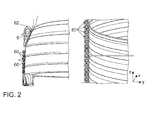
- Fig. 2 on the right the turbulences of the pumped liquid are shown in the gap of a conventional centrifugal pump.
- the gap has a uniform gap width over its entire axial dimension. Numerous small roller movements 60, so-called Taylor Couette instabilities, are formed which lead to high hydraulic losses in the gap.
- Fig. 2 On the left the turbulences of the pumped medium are shown in the gap of a centrifugal pump according to the invention.
- the gap has a widening widening wedge-shaped widening section 5. In the widening section, a single controllable roller movement 62 develops during pump operation, which leads to significantly lower losses overall. The efficiency of the pump is thereby increased.
- the conical portions of the containment shell and the rotor part can be replaced by any geometric contours that are suitable to closely follow the contours of the stator, so that between the rotor part and the housing wall, a widening portion according to claim 1.
- the centrifugal pump according to the invention is not necessarily limited to a radial pump, but may also be, for example, a propeller pump or a diagonal pump.
- the gap can have a further widening section at its end facing away from the conveying region.
Landscapes
- Engineering & Computer Science (AREA)
- Mechanical Engineering (AREA)
- General Engineering & Computer Science (AREA)
- Structures Of Non-Positive Displacement Pumps (AREA)
Abstract
Description
- Die Erfindung betrifft eine Kreiselpumpe mit einem Gehäuse mit einem einen Stator aufnehmenden Statorbereich und einer ein Rotorteil aufnehmenden und von einem Fördermedium durchströmbaren Rotorkammer. Das Rotorteil ist in der Rotorkammer um eine Längsachse drehbar gelagert und weist einen Laufradabschnitt mit Schaufelteilen für das zu fördernde Medium auf. Ein ringförmiger Spalt ist zwischen einem den Stator umlaufenden hinteren Abschnitt des Rotorteils und einer Seitenwand des Gehäuses gebildet.
- Kreiselpumpen mit nasslaufenden Außenläufer-Rotoren sind bekannt. Bei diesen Pumpen tritt das Fördermedium, insbesondere Wasser, über ein Saugrohr in die Rotorkammer ein und wird auf einer Spiralbahn nach außen getragen. Die nach außen hin zunehmende radiale Geschwindigkeit des Fördermediums führt zu einem nach außen zunehmenden Druck, der das Fördermedium in ein Auslassrohr befördert. Das Rotorteil des Motors, das auf einer Welle sitzt, läuft dabei im Fördermedium, das dadurch gleichzeitig die Lager schmieren und den Motor kühlen kann. Die Trennung vom stromführenden Stator des Motors übernimmt eine Abtrennung wie etwa ein Spalttopf oder ein Spaltrohr.
- Konstruktionsbedingt gibt es bei diesen Pumpen in der Rotorkammer einen Förderbereich, der von den Schaufelteilen des Rotorteils durchlaufen wird, so dass das Fördermedium radial nach außen beschleunigt wird, und einen den Stator umlaufenden, ringförmigen Bereich, in dem ein Rotorabschnitt des Rotorteils durch die magnetischen Kräfte der Statorwicklungen angetrieben wird und darin umläuft, wobei das Fördermedium beide Bereiche der Rotorkammer erreicht.
- Herkömmliche Pumpen mit nasslaufendem Außenläufer-Rotor sind u.a. in den Druckschriften
DE 100 09 900 A1 ,US 2007/0177993 A1 undJP 2010-7539 A - Einen besseren Wirkungsgrad weisen Pumpen mit nasslaufenden Innenläufer-Rotoren auf. Allerdings ist das Drehmoment dieser Pumpen regelmäßig geringer. Ferner benötigen Pumpen mit Innenläufer-Rotor einen größeren Bauraum.
- In Anbetracht der beschriebenen Probleme ist es die Aufgabe der vorliegenden Erfindung, eine Kreiselpumpe mit zufriedenstellendem Gesamtwirkungsgrad bereitzustellen, die gleichzeitig einen geringen Platzbedarf hat.
- Diese Aufgabe wird durch eine Weiterbildung der bekannten Kreiselpumpen gelöst, die im Wesentlichen dadurch gekennzeichnet ist, dass der Spalt einen Verbreiterungsabschnitt aufweist, in dem sich die radiale Abmessung des Spalts in axialer Richtung allmählich vergrößert und der sich bevorzugt an seinem vorderen Ende zu einem von Schaufelteilen des Rotorteils durchlaufbaren Förderbereich der Rotorkammer hin öffnet. Dabei erstreckt sich der Verbreiterungsabschnitt in axialer Richtung über eine Länge, die größer ist als 10%, bevorzugt größer ist als 20%, insbesondere größer ist als 30% der Gesamtlänge des Spalts in axialer Richtung.
- Mit anderen Worten hat der radiale Spalt, der zwischen dem Rotorteil und einer Seitenwand des Gehäuses gebildet ist, in axialer Richtung nicht durchwegs eine konstante Spaltbreite, sondern wird in Richtung auf den Förderbereich der Rotorkammer in einem Verbreiterungsabschnitt breiter. Diese Verbreiterung erfolgt allmählich, d.h. nicht in einer einzigen Stufe o. dgl. Insbesondere wird der Spalt in dem Verbreiterungsabschnitt in linearer Weise breiter. Die Länge des Verbreiterungsabschnitts in axialer Richtung ist im Vergleich zu der Gesamtlänge des Spalts groß und beträgt mehr als 10% der Gesamtlänge, insbesondere 30% oder mehr, aber vorzugsweise weniger als 50%. Mit anderen Worten erfolgt die Verbreiterung über eine in axialer Richtung ausgedehnte Strecke. Der gesamte Spalt erstreckt sich dabei in Längsrichtung von dem vorderen Ende des Verbreiterungsabschnitts bis zu dem hinteren Ende des Rotorteils. An das hintere Ende des Verbreiterungsabschnitts schließt sich vorzugsweise ein Spaltabschnitt mit konstanter Spaltbreite in axialer Richtung an, der den hinteren Abschnitt des Rotorteils ringförmig umläuft. Diese konstante Spaltbreite beträgt vorzugsweise mehr als 0,1 mm und weniger als 1,5 mm, insbesondere mehr als 0,3 mm und weniger als 1 mm, da ein Spalt dieser Breite nur einen geringen Einfluss auf die Verluste hat.
- Die Erfindung geht auf die Erkenntnis zurück, dass ein enger Spalt zwischen einer rotierenden inneren Wand und einer stationären äußeren Seitenwand zu der Entstehung zahlreicher kleiner Walzenbewegungen des Fördermediums im Spalt, den sogenannten Taylor-Couette-Instabilitäten, führt. Diese dicht gepackten Walzen haben hohe turbulente Verluste und führen insgesamt zu einem verringerten Wirkungsgrad der Kreiselpumpe. Wenn jedoch die Spaltbreite zunächst groß ist und in Richtung auf den hinteren Abschnitt des Spalts erst allmählich abnimmt, bildet sich eine einzige kontrollierbare Walzenbewegung bzw. ein einziger Wirbel in dem Verbreiterungsabschnitt aus, der deutlich weniger innere Verluste hat, wodurch die Entstehung zahlreicher kleiner Wirbel in diesem Spaltbereich vermieden wird. Insgesamt werden somit die hydraulischen Verluste im Spalt verringert und der Gesamtwirkungsgrad erhöht. Durch die Verlustoptimierung ergibt sich ein geringerer Bedarf an Antriebsleistung bei gleicher hydraulischer Leistung.
- Alternativ oder zusätzlich bildet das hintere Ende des Spalts, das dem Förderbereich abgewandt ist, den Verbreiterungsabschnitt.
- Es hat sich unter hydrodynamischen Gesichtspunkten als vorteilhaft erwiesen, dass die radiale Abmessung des Verbreiterungsabschnitts an dessen vorderem Ende mehr als doppelt so groß, bevorzugt mehr als dreimal so groß, insbesondere viermal so groß ist oder mehr als die radiale Abmessung des Verbreiterungsabschnitts an dessen hinterem Ende. Eine große Eingangsbreite des Spalts ausgehend von dem Förderbereich der Rotorkammer unterstützt die Ausbildung einer einzigen Walzenbewegung des Fördermediums, wodurch die entstehenden Wirbelverluste verringert werden. Andererseits ist die radiale Abmessung des Verbreiterungsabschnitts an dessen vorderem Ende vorzugsweise weniger als 20mal, bevorzugt weniger als 10mal so groß wie die radiale Abmessung des Verbreiterungsabschnitts an dessen hinterem Ende. Eine zu große Eingangsbreite unterstützt nämlich eine nicht gewünschte Strömung des Fördermediums in den Spalt hinein.
- Im Hinblick auf ein optimales Strömungsverhalten des Fördermediums im Spalt hat es sich als zweckmäßig erwiesen, dass sich der Verbreiterungsabschnitt in axialer Richtung über eine Länge erstreckt, die mehr als dreimal so groß, bevorzugt mehr als fünfmal so groß, insbesondere mehr als achtmal so groß ist wie die radiale Abmessung des Spalts an dem hinterem Ende des Verbreiterungsabschnitts (d.h. demjenigen Ende, das dem Förderbereich abgewandt ist).
- Wie bereits angedeutet, kann der sich an das hintere Ende des Verbreiterungsabschnitts anschließende Ringabschnitt des Spalts im Wesentlichen kreiszylindermantelförmig sein. Eine derartige Spaltform behindert ein Umlaufen des Rotors um den Stator nicht und führt zu einem unter hydrodynamischen Gesichtspunkten vorteilhaften Strömungsverhalten des Fördermediums im Spalt.
- Im Hinblick auf eine kostengünstige und einfache Fertigung des Rotorteils ist es zweckmäßig, dass das Rotorteil einen sich in Richtung auf den Förderbereich bevorzugt konusförmig verjüngenden Übergangsabschnitt aufweist, der von dem Verbreiterungsabschnitt des Spalts umlaufen wird. Durch Einbau eines Rotorteils mit sich verjüngendem Übergangsabschnitt in einen Zwischenraum zwischen Gehäusewand und Spalttopf entsteht auf einfache Weise ein Verbreiterungsabschnitt, in dem sich die Spaltbreite in Richtung auf den Förderbereich aufweitet. Ein derart geformtes Rotorteil kann deshalb in herkömmliche Pumpengehäuse eingebaut werden, wodurch eine erfindungsgemäße Kreiselpumpe erhalten wird. Hierdurch können Kosten eingespart werden. Der sich konusförmig verjüngende Übergangsabschnitt des Rotorteils kann von einer der Gehäusewand zugewandten Außenfläche begrenzt werden, die den Teil einer Mantelfläche eines ebenen Kreiskegels bildet.
- Der halbe Öffnungswinkel des Konus ist vorzugsweise größer als 10°, bevorzugt größer als 20°, insbesondere größer als 30°, und bevorzugt kleiner ist als 60°, insbesondere kleiner ist als 40°. Mit anderen Worten ist in einer axialen Schnittebene der Schnittwinkel zwischen der der Gehäusewand zugewandten Außenfläche des Übergangsabschnitts und der Längsachse größer als 10°, bevorzugt größer als 20°, insbesondere größer als 30°, und bevorzugt kleiner ist als 60°, insbesondere kleiner ist als 40°. Ein solcher Öffnungswinkel des Verbreiterungsabschnitts führt zu besonders geringen Wirbelverlusten im Eingangsbereich des Spalts.
- Dabei kann die Dicke des Übergangsabschnitts in radialer Richtung im Wesentlichen der Dicke eines kreiszylindermantelförmigen Rohrabschnitts des Rotorteils entsprechen, der sich an das hintere Ende des Übergangsabschnitts anschließt. Ein derart geformtes Rotorteil erlaubt eine einfache maßliche Überwachung im Fertigungsprozess der Bauteile, insbesondere wenn der Übergangsabschnitt konisch und der sich daran anschließende Rohrabschnitt zylindrisch geformt ist.
- In einer besonders bevorzugten Ausführungsform weist die erfindungsgemäße Kreiselpumpe eine in den Innenraum des Gehäuses vorstehende Abtrennung auf, insbesondere in Form eines Spaltrohrs oder Spalttopfs, der den Statorbereich von der Rotorkammer trennt, wobei der hintere Abschnitt des Rotorteils in einem Zwischenraum zwischen der Gehäusewand und einer umlaufenden Wand des Spalttopfs aufgenommen ist.
- Dabei kann die umlaufende Wand des Spalttopfs einen im Wesentlichen zylindermantelförmigen Teil und einen im Wesentlichen kegelmantelförmigen Teil aufweisen, die jeweils einer Innenseite des Rotorteils zugewandt sind. Vorzugsweise ist der Spalttopf so geformt, dass er die Konturen des Stators möglichst eng umschließt, während der Rotor mit seiner Innen- und Außenkontur wiederum der Kontur des Spalttopfs folgen kann. Eine derartige Ausgestaltung von Spalttopf und Rotor führt zu besonders geringen Verlusten durch ungewünschte Strömungen in den Spalten auf beiden Seiten des Rotorteils und somit zu einem insgesamt höheren Wirkungsgrad der Pumpe.
- In diesem Zusammenhang hat es sich als zweckmäßig erwiesen, dass der kegelmantelförmige Teil der Spalttopfwand, die diesem Teil zugewandte innere Begrenzungsfläche des Rotorteils und die dem Verbreiterungsabschnitt des Spalts zugewandte äußere Begrenzungsfläche des Rotorteils im Wesentlichen parallel zueinander verlaufen, während sie vorzugsweise einen Winkel von mehr als 10°, insbesondere mehr als 30°, aber vorzugsweise weniger als 50° mit der Längsachse einschließen. Ein Rotorteil mit einem derart geformten Übergangsabschnitt zwischen dem den Stator umlaufenden Abschnitt und dem Laufradabschnitt mit Schaufelteilen ist besonders stabil und dreht sich besonders gleichmäßig.
- Gemäß einem weiteren Aspekt der Erfindung weist der Spalt den Verbreiterungsabschnitt oder einen weiteren Verbreiterungsabschnitt an seinem dem Förderbereich abgewandten hinteren Ende auf. Die Spaltkontur und die Spaltabmessungen des (weiteren) Verbreiterungsabschnitts können mit den oben beschriebenen Konturen und Abmessungen des Verbreiterungsabschnitts übereinstimmen, und es wird zur Vermeidung von Wiederholungen auf die obigen Ausführungen verwiesen.
- In dem weiteren Verbreiterungsabschnitt kann sich eine einzige kontrollierbare Walzenbewegung des Fördermediums ausbilden, die zu deutlich weniger Verlusten führt als ein durchgehend schmaler Spalt, in dem sich bei Drehung des Rotors zahlreiche kleine Walzenbewegungen (Taylor-Couette-Instabilitäten) ausbilden, die zu hohen inneren Verlusten führen. Der Wirkungsgrad der Kreiselpumpe wird dadurch erhöht.
- Die Erfindung wird nachfolgend anhand eines in einer Zeichnung dargestellten Ausführungsbeispiels näher erläutert. In der Zeichnung zeigt
- Fig. 1:
- eine erfindungsgemäße Kreiselpumpe in einer schematischen Querschnittsansicht, und
- Fig. 2:
- die Turbulenzen des Fördermediums im Spalt einer herkömmlichen Kreiselpumpe (rechts) und die Turbulenzen des Fördermediums im Spalt einer erfindungsgemäßen Kreiselpumpe mit Verbreiterungsabschnitt (links).
-
Fig. 1 zeigt eine erfindungsgemäße Kreiselpumpe 10 in einer Querschnittsansicht. Ein Fördermedium, insbesondere Wasser, wird der Pumpe durch ein Einlassrohr 52 zugeführt und in Richtung auf ein Auslassrohr 54 gepumpt. Eine radiale Beschleunigung des Wassers wird durch ein mit Schaufelteilen 32 besetztes Rotorteil 3 erzeugt, das um eine Längsachse A drehbar gelagert ist. - Die Pumpe 10 weist ein Gehäuse 4 auf, das im Inneren eine von dem Fördermedium durchströmte Rotorkammer 31 und einen den Stator 2 aufnehmenden Statorbereich 22 ausbildet. Die Rotorkammer 31 und der Statorbereich 22 sind durch einen in das Gehäuseinnere vorragenden Spalttopf 1 voneinander getrennt. Der Spalttopf 1 bildet im Gehäuseinneren eine umlaufende Spalttopfwand 1.1, 1.2 aus, die derart geformt ist, dass ein ringförmiger Zwischenraum zwischen der Spalttopfwand und einer Seitenwand 42 des Gehäuses 4 gebildet ist.
- Das Rotorteil 3 weist einen dem Einlassrohr 52 zugewandten vorderen Abschnitt mit den Schaufelteilen 32 auf, die in einen Förderbereich 33 der Rotorkammer 31 hineinragen. Ferner weist das Rotorteil 3 einen hinteren Abschnitt auf, der den Spalttopf 1 ringförmig umläuft und in dem Zwischenraum zwischen der Spalttopfwand 1.1, 1.2 und der Gehäusewand 42 aufgenommen ist. Der hintere Abschnitt der Rotorteils weist einen im Wesentlichen zylindermantelförmigen Rohrabschnitt 3.1 und einen sich konusförmig verjüngenden Übergangsabschnitt 3.2 auf, der den Rohrabschnitt 3.1 mit dem vorderen Rotorteilabschnitt verbindet. Der hintere Abschnitt des Rotorteils 3 wird infolge des durch Wicklungen 6 des Stators 2 erzeugten magnetischen Felds angetrieben, so dass der drehfest damit verbundene vordere Abschnitt des Rotorteils 3 ebenfalls in Drehung versetzt wird. Die sich bewegenden Schaufelteile 32 beschleunigen das Fördermedium radial nach außen.
- Zwischen dem hinteren Abschnitt des Rotorteils 3 und der Seitenwand 42 des Gehäuses 4 ist ein Spalt 7 gebildet. Der Spalt 7 umfasst einen Verbreiterungsabschnitt 5, in dem sich die radiale Abmessung des Spalts in axialer Richtung A in Richtung auf den Förderbereich 33 allmählich vergrößert und der an seinem vorderen Ende in den Förderbereich 33 der Rotorkammer 31 übergeht.
- Dabei erstreckt sich der Verbreiterungsabschnitt 5 in axialer Richtung über eine Länge L, die größer ist als 10% der Gesamtlänge G des Spalts 7 in axialer Richtung. In der dargestellten Ausführungsform beträgt die Länge L des Verbreiterungsabschnitts 5 etwa 35% der Gesamtlänge G des Spalts 7. Auf diese Weise entsteht ein im Vergleich zu der Gesamtlänge des Rotors in axialer Richtung ausgedehnter Verbreiterungsabschnitt, der zu der Ausbildung einer kontrollierbaren Walzenbewegung des Fördermediums im Übergangsbereich zwischen dem Förderbereich 33 und dem Spalt 7 führt, wodurch hydraulische Spaltverluste vermieden werden können.
- Ferner erstreckt sich der Verbreiterungsabschnitt 5 in axialer Richtung A über eine Länge L, die mehr als achtmal so groß ist wie die radiale Abmessung X des Spalts an dem hinterem Ende des Verbreiterungsabschnitts 5, an dem die Spaltbreite klein ist. Zusätzlich ist die radiale Abmessung des Verbreiterungsabschnitts 5 an dessen vorderem Ende mehr als viermal so groß wie an dessen hinterem Ende. Somit weitet sich der Spalt im Verbreiterungsabschnitt stark auf.
- Der Rohrabschnitt 3.1 des Rotorteils 3 und der Übergangsabschnitt 3.2 des Rotorteils 3 weisen in radialer Richtung etwa dieselbe Dicke auf. Der Übergangsabschnitt 3.2 verläuft in der Querschnittsansicht der
Fig. 1 unter einem Winkel α/2 zu der Längsachse A, während der zylindermantelförmige Rohrabschnitt 3.1 etwa parallel zu der Längsachse A verläuft. Der Winkel α/2 beträgt mehr als 20° und weniger als 40°, insbesondere etwa 30° und entspricht dem Öffnungswinkel des Verbreiterungsabschnitts des Spalts 7. Mit anderen Worten verjüngt sich der Übergangsabschnitt 3.2 in Richtung auf den Förderbereich 33 konusförmig. In dem Verbreiterungsabschnitt 5 des Spalts 7 wird die Spaltbreite dadurch in Richtung auf den Förderbereich 33 in linearer Weise breiter. Der Spalttopf 1 weist ebenfalls einen zylindermantelförmigen Teil 1.1, der von dem Rohrabschnitt 3.1 des Rotorteils 3 umlaufen wird, und einen sich konusförmig verjüngenden Teil 1.2 auf, der von dem Übergangsabschnitt 3.2 des Rotorteils 3 umlaufen wird. An den konusförmigen Abschnitt 1.2 des Spalttopfs 1 schließt sich eine im Wesentlichen flache Decke des Spalttopfs 1 an, die sich etwa in radialer Richtung erstreckt. Dabei folgt der Spalttopf 1 eng den Konturen des Stators, den er umgibt. Die dem Spalttopf 1 zugewandte innere Begrenzungsfläche des Übergangsabschnitts 3.2 und die dem Verbreiterungsabschnitt 5 zugewandte äußere Begrenzungsfläche des Übergangsabschnitts 3.2 verlaufen im Wesentlichen parallel zueinander und parallel zu dem konusförmigen Teil 1.2 des Spalttopfs. - In
Fig. 2 rechts sind die Turbulenzen des Fördermediums im Spalt einer herkömmlichen Kreiselpumpe dargestellt. Der Spalt weist eine einheitliche Spaltbreite über seine gesamte axiale Abmessung auf. Es bilden sich zahlreiche kleine Walzenbewegungen 60, sogenannte Taylor-Couette-Instabilitäten aus, die zu hohen hydraulischen Verlusten im Spalt führen. InFig. 2 links sind die Turbulenzen des Fördermediums im Spalt einer erfindungsgemäßen Kreiselpumpe dargestellt. Der Spalt weist einen sich keilförmig nach oben hin verbreiternden Verbreiterungsabschnitt 5 auf. In dem Verbreiterungsabschnitt bildet sich bei Pumpenbetrieb eine einzige kontrollierbare Walzenbewegung 62 aus, die insgesamt zu deutlich geringeren Verlusten führt. Der Wirkungsgrad der Pumpe wird dadurch erhöht. - Andere Ausgestaltungen des Verbreiterungsabschnitts 33 sind ebenso vorstellbar. Insbesondere können die konischen Anteile des Spalttopfs und des Rotorteils durch beliebige geometrische Konturen ersetzt werden, die geeignet sind, den Konturen des Stators eng zu folgen, so dass zwischen Rotorteil und Gehäusewand ein Verbreiterungsabschnitt gemäß Anspruch 1 entsteht. Außerdem kann von den parallelen Konturen abgewichen werden. Im Übrigen ist die erfindungsgemäße Kreiselpumpe nicht notwendigerweise auf eine Radialpumpe beschränkt, sondern kann auch bspw. eine Propellerpumpe oder eine Diagonalpumpe sein. Ferner kann der Spalt an seinem dem Förderbereich abgewandten Ende einen weiteren Verbreiterungsabschnitt aufweisen.
-
- 1
- Spalttopf
- 1.1
- zylindermantelförmiger Teil der Spalttopfwand
- 1.2
- kegelmantelförmiger Teil der Spalttopfwand
- 2
- Stator
- 3
- Rotorteil
- 3.1
- Rohrabschnitt des Rotorteils
- 3.2
- Übergangsabschnitt des Rotorteils
- 4
- Gehäuse
- 5
- Verbreiterungsabschnitt des Spalts
- 7
- Spalt
- 8
- Ringabschnitt des Spalts
- 10
- Kreiselpumpe
- 22
- Statorbereich
- 31
- Rotorkammer
- 32
- Schaufelteile
- 33
- Förderbereich
- 42
- Seitenwand
- 50
- Einlassrohr
- 52
- Auslassrohr
- 60
- Walzenbewegungen
- 62
- Walzenbewegung im Verbreiterungsabschnitt
- A
- Längsachse
- L
- Länge des Verbreiterungsabschnitts des Spalts
- G
- Gesamtlänge des Spalts
- X, Y
- radiale Abmessungen des Spalts
Claims (11)
- Kreiselpumpe (10) mit einem Gehäuse (4) mit einem einen Stator (2) aufnehmenden Statorbereich (22) und einer ein um eine Längsachse (A) drehbar gelagertes Rotorteil (3) aufnehmenden und von einem Fördermedium durchströmbaren Rotorkammer (31),
wobei ein ringförmiger Spalt (7) zwischen einem den Stator umlaufenden hinteren Abschnitt des Rotorteils und einer Seitenwand (42) des Gehäuses (4) gebildet ist, dadurch gekennzeichnet,
dass der Spalt einen Verbreiterungsabschnitt (5) aufweist, in dem sich die radiale Abmessung (X) des Spalts (7) in axialer Richtung (A) allmählich vergrößert und der sich in axialer Richtung (A) über eine Länge (L) erstreckt, die größer ist als 10%, bevorzugt größer ist als 20%, insbesondere größer ist als 30% der Gesamtlänge (G) des Spalts (7) in axialer Richtung (A), wobei sich vorzugsweise der Verbreiterungsabschnitt an seinem vorderen Ende zu einem von Schaufelteilen (32) des Rotorteils (3) durchlaufbaren Förderbereich der Rotorkammer (31) hin öffnet. - Kreiselpumpe nach Anspruch 1, dadurch gekennzeichnet, dass die radiale Abmessung (Y) des Verbreiterungsabschnitts (5) an dessen vorderem Ende mehr als doppelt so groß, bevorzugt mehr als dreimal so groß, insbesondere viermal so groß ist oder mehr als die radiale Abmessung (X) des Verbreiterungsabschnitts an dessen hinterem Ende.
- Kreiselpumpe nach Anspruch 1 oder 2, dadurch gekennzeichnet, dass die Länge (L) des Verbreiterungsabschnitts mehr als dreimal so groß, bevorzugt mehr als fünfmal so groß, insbesondere mehr als achtmal so groß ist wie die radiale Abmessung (X) des Spalts an dem hinterem Ende des Verbreiterungsabschnitts.
- Kreiselpumpe nach einem der vorhergehenden Ansprüche, dadurch gekennzeichnet, dass ein sich an das hintere Ende des Verbreiterungsabschnitts (5) anschließender Ringabschnitt (8) des Spalts (7) im Wesentlichen kreiszylindermantelförmig ist.
- Kreiselpumpe nach einem der vorhergehenden Ansprüche, dadurch gekennzeichnet, dass das Rotorteil (3) einen sich in Richtung auf den Förderbereich bevorzugt konusförmig verjüngenden Übergangsabschnitt (3.2) aufweist, der von dem Verbreiterungsabschnitt (5) des Spalts umlaufen wird.
- Kreiselpumpe nach Anspruch 5, dadurch gekennzeichnet, dass der halbe Öffnungswinkel (α/2) des Konus größer ist als 10°, bevorzugt größer ist als 20°, insbesondere größer ist als 30° und kleiner ist als 60°, insbesondere kleiner ist als 40°.
- Kreiselpumpe nach Anspruch 5 oder 6, dadurch gekennzeichnet, dass die Dicke des Übergangsabschnitts (3.2) in radialer Richtung im Wesentlichen der Dicke eines kreiszylindermantelförmigen Rohrabschnitts (3.1) entspricht, der sich an das hintere Ende des Übergangsabschnitts (3.2) anschließt.
- Kreiselpumpe nach einem der vorhergehenden Ansprüche, gekennzeichnet durch einen in den Innenraum des Gehäuses (4) vorstehenden Spalttopf (1), der den Statorbereich (22) von der Rotorkammer (31) trennt, wobei der hintere Abschnitt des Rotors in einem Zwischenraum zwischen der Gehäusewand (42) und einer umlaufenden Wand des Spalttopfs (1) aufgenommen ist.
- Kreiselpumpe nach Anspruch 8, dadurch gekennzeichnet, dass die umlaufende Wand des Spalttopfs (1) einen im Wesentlichen zylindermantelförmigen Teil (1.1) und einen im Wesentlichen kegelmantelförmigen Teil (1.2) aufweist, die jeweils einer Innenseite des Rotorteils zugewandt sind.
- Kreiselpumpe nach Anspruch 8 oder 9, dadurch gekennzeichnet, dass der kegelmantelförmige Teil (1.2) der Spalttopfwand, die diesem Teil zugewandte innere Begrenzungsfläche des Rotorteils (3) und die dem Verbreiterungsabschnitt (5) des Spalts zugewandte äußere Begrenzungsfläche des Rotorteils (3) im Wesentlichen parallel zueinander verlaufen.
- Kreiselpumpe nach einem der vorhergehenden Ansprüche, dadurch gekennzeichnet, dass der Spalt den Verbreiterungsabschnitt oder einen weiteren Verbreiterungsabschnitt an seinem der Förderkammer abgewandten hinteren Ende aufweist.
Applications Claiming Priority (1)
| Application Number | Priority Date | Filing Date | Title |
|---|---|---|---|
| DE201310221245 DE102013221245A1 (de) | 2013-10-21 | 2013-10-21 | Nassläuferpumpe |
Publications (2)
| Publication Number | Publication Date |
|---|---|
| EP2863062A1 true EP2863062A1 (de) | 2015-04-22 |
| EP2863062B1 EP2863062B1 (de) | 2020-04-15 |
Family
ID=51585005
Family Applications (1)
| Application Number | Title | Priority Date | Filing Date |
|---|---|---|---|
| EP14185729.2A Active EP2863062B1 (de) | 2013-10-21 | 2014-09-22 | Nassläuferpumpe |
Country Status (3)
| Country | Link |
|---|---|
| EP (1) | EP2863062B1 (de) |
| CN (1) | CN204511907U (de) |
| DE (1) | DE102013221245A1 (de) |
Citations (5)
| Publication number | Priority date | Publication date | Assignee | Title |
|---|---|---|---|---|
| US5049134A (en) * | 1989-05-08 | 1991-09-17 | The Cleveland Clinic Foundation | Sealless heart pump |
| DE10009900A1 (de) | 2000-03-01 | 2001-09-06 | Pierburg Ag | Elektrisch kommutierter Motor und Ansteuerverfahren dafür |
| US20050249609A1 (en) * | 2004-03-31 | 2005-11-10 | Kabushiki Kaisha Toshiba | Fluid pump, cooling system and electrical appliance |
| US20070177993A1 (en) | 2006-01-31 | 2007-08-02 | Asian Kogyo Kabushiki Kaisha | Electric pump |
| JP2010007539A (ja) | 2008-06-26 | 2010-01-14 | Hitachi Automotive Systems Ltd | 電動遠心ポンプ |
Family Cites Families (6)
| Publication number | Priority date | Publication date | Assignee | Title |
|---|---|---|---|---|
| DE19934382A1 (de) * | 1999-07-22 | 2001-02-01 | Bosch Gmbh Robert | Flüssigkeitspumpe |
| DE19948972A1 (de) * | 1999-10-12 | 2001-04-19 | Bosch Gmbh Robert | Motorpumpe |
| DE202005017738U1 (de) * | 2004-11-19 | 2006-02-09 | Ebm-Papst St. Georgen Gmbh & Co. Kg | Anordnung mit einem Lüfter und einer Pumpe |
| JP2009074433A (ja) * | 2007-09-20 | 2009-04-09 | Panasonic Electric Works Co Ltd | ポンプ |
| EP2273123B9 (de) * | 2009-07-08 | 2018-03-21 | Pierburg Pump Technology GmbH | Sicherung eines Pumpenlaufrades |
| JP5766277B2 (ja) * | 2010-04-19 | 2015-08-19 | ピールブルグ パンプ テクノロジー ゲゼルシャフト ミット ベシュレンクテル ハフツングPierburg Pump Technology GmbH | 自動車に用いられる電動式の冷媒ポンプ |
-
2013
- 2013-10-21 DE DE201310221245 patent/DE102013221245A1/de not_active Withdrawn
-
2014
- 2014-09-22 EP EP14185729.2A patent/EP2863062B1/de active Active
- 2014-10-21 CN CN201420610808.7U patent/CN204511907U/zh not_active Expired - Lifetime
Patent Citations (5)
| Publication number | Priority date | Publication date | Assignee | Title |
|---|---|---|---|---|
| US5049134A (en) * | 1989-05-08 | 1991-09-17 | The Cleveland Clinic Foundation | Sealless heart pump |
| DE10009900A1 (de) | 2000-03-01 | 2001-09-06 | Pierburg Ag | Elektrisch kommutierter Motor und Ansteuerverfahren dafür |
| US20050249609A1 (en) * | 2004-03-31 | 2005-11-10 | Kabushiki Kaisha Toshiba | Fluid pump, cooling system and electrical appliance |
| US20070177993A1 (en) | 2006-01-31 | 2007-08-02 | Asian Kogyo Kabushiki Kaisha | Electric pump |
| JP2010007539A (ja) | 2008-06-26 | 2010-01-14 | Hitachi Automotive Systems Ltd | 電動遠心ポンプ |
Also Published As
| Publication number | Publication date |
|---|---|
| CN204511907U (zh) | 2015-07-29 |
| EP2863062B1 (de) | 2020-04-15 |
| DE102013221245A1 (de) | 2015-04-23 |
Similar Documents
| Publication | Publication Date | Title |
|---|---|---|
| DE69626768T2 (de) | Vorrichtung zum Pumpen oder Verdichten eines mehrphasigen Fluids mit einer Tandem Beschaufelung | |
| DE60111879T2 (de) | Inline-Pumpe | |
| DE102014201487B3 (de) | Kreiselpumpenlaufrad | |
| EP1719914B1 (de) | Kreiselpumpe mit Magnetkupplung | |
| DE102013217261A1 (de) | Kompressor | |
| DE102018104247A1 (de) | Zentrifugalkompressor | |
| EP2382393A1 (de) | Seitenkanalgebläse, insbesondere sekundärluftgebläse für eine verbrennungskraftmaschine | |
| DE102015100215B4 (de) | Seitenkanalgebläse für eine Verbrennungskraftmaschine | |
| DE102012020228A1 (de) | Fluiddynamisches Lagersystem | |
| EP3205004B1 (de) | Käfigläufer für eine elektrische asynchronmaschine mit einen kurzschlussring stabilisierender stützscheibe | |
| DE1403853A1 (de) | Rotierende Einrichtung zum Bewegen eines fluessigen oder gasfoermigen Mediums | |
| EP2207979B1 (de) | Hydrodynamische maschine, insbesondere hydrodynamischer retarder | |
| DE102007030281A1 (de) | Hydrodynamische Kupplung | |
| EP3608545B1 (de) | Vakuumpumpe | |
| DE102015003224B4 (de) | Selbstansaugende Pumpe | |
| DE102014224657B4 (de) | Klimatisierungsanlage mit Radialgebläse | |
| WO2013092982A1 (de) | Verdichter und verfahren zum betrieb eines verdichters | |
| EP2342464B1 (de) | Seitenkanalgebläse, insbesondere sekundärluftgebläse für eine verbrennungskraftmaschine | |
| DE102019101277A1 (de) | Axiallüfteranordnung für Fahrzeuge | |
| DE897616C (de) | Axial oder konisch durchstroemtes Geblaese oder axial oder konisch durchstroemte Pumpe zur Foerderung von Gasen oder Fluessigkeiten mit positivem Reaktionsgrad | |
| DE102015104438A1 (de) | Vakuumsystem | |
| EP2863062B1 (de) | Nassläuferpumpe | |
| DE69415269T2 (de) | Zusammenbau einer Brennstoffpumpe | |
| WO2021032487A1 (de) | Pumpvorrichtung umfassend ein radiallager | |
| EP3032106B1 (de) | Vakuumpumpe |
Legal Events
| Date | Code | Title | Description |
|---|---|---|---|
| PUAI | Public reference made under article 153(3) epc to a published international application that has entered the european phase |
Free format text: ORIGINAL CODE: 0009012 |
|
| 17P | Request for examination filed |
Effective date: 20140922 |
|
| AK | Designated contracting states |
Kind code of ref document: A1 Designated state(s): AL AT BE BG CH CY CZ DE DK EE ES FI FR GB GR HR HU IE IS IT LI LT LU LV MC MK MT NL NO PL PT RO RS SE SI SK SM TR |
|
| AX | Request for extension of the european patent |
Extension state: BA ME |
|
| RIC1 | Information provided on ipc code assigned before grant |
Ipc: F04D 13/06 20060101AFI20150715BHEP |
|
| R17P | Request for examination filed (corrected) |
Effective date: 20151022 |
|
| RBV | Designated contracting states (corrected) |
Designated state(s): AL AT BE BG CH CY CZ DE DK EE ES FI FR GB GR HR HU IE IS IT LI LT LU LV MC MK MT NL NO PL PT RO RS SE SI SK SM TR |
|
| STAA | Information on the status of an ep patent application or granted ep patent |
Free format text: STATUS: EXAMINATION IS IN PROGRESS |
|
| 17Q | First examination report despatched |
Effective date: 20181214 |
|
| GRAP | Despatch of communication of intention to grant a patent |
Free format text: ORIGINAL CODE: EPIDOSNIGR1 |
|
| STAA | Information on the status of an ep patent application or granted ep patent |
Free format text: STATUS: GRANT OF PATENT IS INTENDED |
|
| INTG | Intention to grant announced |
Effective date: 20191107 |
|
| GRAS | Grant fee paid |
Free format text: ORIGINAL CODE: EPIDOSNIGR3 |
|
| GRAA | (expected) grant |
Free format text: ORIGINAL CODE: 0009210 |
|
| STAA | Information on the status of an ep patent application or granted ep patent |
Free format text: STATUS: THE PATENT HAS BEEN GRANTED |
|
| AK | Designated contracting states |
Kind code of ref document: B1 Designated state(s): AL AT BE BG CH CY CZ DE DK EE ES FI FR GB GR HR HU IE IS IT LI LT LU LV MC MK MT NL NO PL PT RO RS SE SI SK SM TR |
|
| REG | Reference to a national code |
Ref country code: CH Ref legal event code: EP |
|
| REG | Reference to a national code |
Ref country code: DE Ref legal event code: R096 Ref document number: 502014013975 Country of ref document: DE |
|
| REG | Reference to a national code |
Ref country code: IE Ref legal event code: FG4D Free format text: LANGUAGE OF EP DOCUMENT: GERMAN |
|
| REG | Reference to a national code |
Ref country code: AT Ref legal event code: REF Ref document number: 1257623 Country of ref document: AT Kind code of ref document: T Effective date: 20200515 |
|
| REG | Reference to a national code |
Ref country code: NL Ref legal event code: MP Effective date: 20200415 |
|
| REG | Reference to a national code |
Ref country code: LT Ref legal event code: MG4D |
|
| PG25 | Lapsed in a contracting state [announced via postgrant information from national office to epo] |
Ref country code: IS Free format text: LAPSE BECAUSE OF FAILURE TO SUBMIT A TRANSLATION OF THE DESCRIPTION OR TO PAY THE FEE WITHIN THE PRESCRIBED TIME-LIMIT Effective date: 20200815 Ref country code: GR Free format text: LAPSE BECAUSE OF FAILURE TO SUBMIT A TRANSLATION OF THE DESCRIPTION OR TO PAY THE FEE WITHIN THE PRESCRIBED TIME-LIMIT Effective date: 20200716 Ref country code: NO Free format text: LAPSE BECAUSE OF FAILURE TO SUBMIT A TRANSLATION OF THE DESCRIPTION OR TO PAY THE FEE WITHIN THE PRESCRIBED TIME-LIMIT Effective date: 20200715 Ref country code: FI Free format text: LAPSE BECAUSE OF FAILURE TO SUBMIT A TRANSLATION OF THE DESCRIPTION OR TO PAY THE FEE WITHIN THE PRESCRIBED TIME-LIMIT Effective date: 20200415 Ref country code: SE Free format text: LAPSE BECAUSE OF FAILURE TO SUBMIT A TRANSLATION OF THE DESCRIPTION OR TO PAY THE FEE WITHIN THE PRESCRIBED TIME-LIMIT Effective date: 20200415 Ref country code: LT Free format text: LAPSE BECAUSE OF FAILURE TO SUBMIT A TRANSLATION OF THE DESCRIPTION OR TO PAY THE FEE WITHIN THE PRESCRIBED TIME-LIMIT Effective date: 20200415 Ref country code: PT Free format text: LAPSE BECAUSE OF FAILURE TO SUBMIT A TRANSLATION OF THE DESCRIPTION OR TO PAY THE FEE WITHIN THE PRESCRIBED TIME-LIMIT Effective date: 20200817 Ref country code: NL Free format text: LAPSE BECAUSE OF FAILURE TO SUBMIT A TRANSLATION OF THE DESCRIPTION OR TO PAY THE FEE WITHIN THE PRESCRIBED TIME-LIMIT Effective date: 20200415 |
|
| PG25 | Lapsed in a contracting state [announced via postgrant information from national office to epo] |
Ref country code: BG Free format text: LAPSE BECAUSE OF FAILURE TO SUBMIT A TRANSLATION OF THE DESCRIPTION OR TO PAY THE FEE WITHIN THE PRESCRIBED TIME-LIMIT Effective date: 20200715 Ref country code: RS Free format text: LAPSE BECAUSE OF FAILURE TO SUBMIT A TRANSLATION OF THE DESCRIPTION OR TO PAY THE FEE WITHIN THE PRESCRIBED TIME-LIMIT Effective date: 20200415 Ref country code: LV Free format text: LAPSE BECAUSE OF FAILURE TO SUBMIT A TRANSLATION OF THE DESCRIPTION OR TO PAY THE FEE WITHIN THE PRESCRIBED TIME-LIMIT Effective date: 20200415 Ref country code: HR Free format text: LAPSE BECAUSE OF FAILURE TO SUBMIT A TRANSLATION OF THE DESCRIPTION OR TO PAY THE FEE WITHIN THE PRESCRIBED TIME-LIMIT Effective date: 20200415 |
|
| PG25 | Lapsed in a contracting state [announced via postgrant information from national office to epo] |
Ref country code: AL Free format text: LAPSE BECAUSE OF FAILURE TO SUBMIT A TRANSLATION OF THE DESCRIPTION OR TO PAY THE FEE WITHIN THE PRESCRIBED TIME-LIMIT Effective date: 20200415 |
|
| REG | Reference to a national code |
Ref country code: DE Ref legal event code: R097 Ref document number: 502014013975 Country of ref document: DE |
|
| PG25 | Lapsed in a contracting state [announced via postgrant information from national office to epo] |
Ref country code: EE Free format text: LAPSE BECAUSE OF FAILURE TO SUBMIT A TRANSLATION OF THE DESCRIPTION OR TO PAY THE FEE WITHIN THE PRESCRIBED TIME-LIMIT Effective date: 20200415 Ref country code: SM Free format text: LAPSE BECAUSE OF FAILURE TO SUBMIT A TRANSLATION OF THE DESCRIPTION OR TO PAY THE FEE WITHIN THE PRESCRIBED TIME-LIMIT Effective date: 20200415 Ref country code: DK Free format text: LAPSE BECAUSE OF FAILURE TO SUBMIT A TRANSLATION OF THE DESCRIPTION OR TO PAY THE FEE WITHIN THE PRESCRIBED TIME-LIMIT Effective date: 20200415 Ref country code: IT Free format text: LAPSE BECAUSE OF FAILURE TO SUBMIT A TRANSLATION OF THE DESCRIPTION OR TO PAY THE FEE WITHIN THE PRESCRIBED TIME-LIMIT Effective date: 20200415 Ref country code: RO Free format text: LAPSE BECAUSE OF FAILURE TO SUBMIT A TRANSLATION OF THE DESCRIPTION OR TO PAY THE FEE WITHIN THE PRESCRIBED TIME-LIMIT Effective date: 20200415 Ref country code: CZ Free format text: LAPSE BECAUSE OF FAILURE TO SUBMIT A TRANSLATION OF THE DESCRIPTION OR TO PAY THE FEE WITHIN THE PRESCRIBED TIME-LIMIT Effective date: 20200415 Ref country code: ES Free format text: LAPSE BECAUSE OF FAILURE TO SUBMIT A TRANSLATION OF THE DESCRIPTION OR TO PAY THE FEE WITHIN THE PRESCRIBED TIME-LIMIT Effective date: 20200415 |
|
| PLBE | No opposition filed within time limit |
Free format text: ORIGINAL CODE: 0009261 |
|
| STAA | Information on the status of an ep patent application or granted ep patent |
Free format text: STATUS: NO OPPOSITION FILED WITHIN TIME LIMIT |
|
| PG25 | Lapsed in a contracting state [announced via postgrant information from national office to epo] |
Ref country code: PL Free format text: LAPSE BECAUSE OF FAILURE TO SUBMIT A TRANSLATION OF THE DESCRIPTION OR TO PAY THE FEE WITHIN THE PRESCRIBED TIME-LIMIT Effective date: 20200415 Ref country code: SK Free format text: LAPSE BECAUSE OF FAILURE TO SUBMIT A TRANSLATION OF THE DESCRIPTION OR TO PAY THE FEE WITHIN THE PRESCRIBED TIME-LIMIT Effective date: 20200415 |
|
| 26N | No opposition filed |
Effective date: 20210118 |
|
| PG25 | Lapsed in a contracting state [announced via postgrant information from national office to epo] |
Ref country code: MC Free format text: LAPSE BECAUSE OF FAILURE TO SUBMIT A TRANSLATION OF THE DESCRIPTION OR TO PAY THE FEE WITHIN THE PRESCRIBED TIME-LIMIT Effective date: 20200415 |
|
| REG | Reference to a national code |
Ref country code: CH Ref legal event code: PL |
|
| PG25 | Lapsed in a contracting state [announced via postgrant information from national office to epo] |
Ref country code: SI Free format text: LAPSE BECAUSE OF FAILURE TO SUBMIT A TRANSLATION OF THE DESCRIPTION OR TO PAY THE FEE WITHIN THE PRESCRIBED TIME-LIMIT Effective date: 20200415 |
|
| REG | Reference to a national code |
Ref country code: BE Ref legal event code: MM Effective date: 20200930 |
|
| PG25 | Lapsed in a contracting state [announced via postgrant information from national office to epo] |
Ref country code: LU Free format text: LAPSE BECAUSE OF NON-PAYMENT OF DUE FEES Effective date: 20200922 |
|
| PG25 | Lapsed in a contracting state [announced via postgrant information from national office to epo] |
Ref country code: LI Free format text: LAPSE BECAUSE OF NON-PAYMENT OF DUE FEES Effective date: 20200930 Ref country code: IE Free format text: LAPSE BECAUSE OF NON-PAYMENT OF DUE FEES Effective date: 20200922 Ref country code: CH Free format text: LAPSE BECAUSE OF NON-PAYMENT OF DUE FEES Effective date: 20200930 Ref country code: BE Free format text: LAPSE BECAUSE OF NON-PAYMENT OF DUE FEES Effective date: 20200930 |
|
| REG | Reference to a national code |
Ref country code: AT Ref legal event code: MM01 Ref document number: 1257623 Country of ref document: AT Kind code of ref document: T Effective date: 20200922 |
|
| PG25 | Lapsed in a contracting state [announced via postgrant information from national office to epo] |
Ref country code: AT Free format text: LAPSE BECAUSE OF NON-PAYMENT OF DUE FEES Effective date: 20200922 |
|
| PG25 | Lapsed in a contracting state [announced via postgrant information from national office to epo] |
Ref country code: TR Free format text: LAPSE BECAUSE OF FAILURE TO SUBMIT A TRANSLATION OF THE DESCRIPTION OR TO PAY THE FEE WITHIN THE PRESCRIBED TIME-LIMIT Effective date: 20200415 Ref country code: MT Free format text: LAPSE BECAUSE OF FAILURE TO SUBMIT A TRANSLATION OF THE DESCRIPTION OR TO PAY THE FEE WITHIN THE PRESCRIBED TIME-LIMIT Effective date: 20200415 Ref country code: CY Free format text: LAPSE BECAUSE OF FAILURE TO SUBMIT A TRANSLATION OF THE DESCRIPTION OR TO PAY THE FEE WITHIN THE PRESCRIBED TIME-LIMIT Effective date: 20200415 |
|
| PG25 | Lapsed in a contracting state [announced via postgrant information from national office to epo] |
Ref country code: MK Free format text: LAPSE BECAUSE OF FAILURE TO SUBMIT A TRANSLATION OF THE DESCRIPTION OR TO PAY THE FEE WITHIN THE PRESCRIBED TIME-LIMIT Effective date: 20200415 |
|
| P01 | Opt-out of the competence of the unified patent court (upc) registered |
Effective date: 20230523 |
|
| PGFP | Annual fee paid to national office [announced via postgrant information from national office to epo] |
Ref country code: DE Payment date: 20250930 Year of fee payment: 12 |
|
| PGFP | Annual fee paid to national office [announced via postgrant information from national office to epo] |
Ref country code: GB Payment date: 20250923 Year of fee payment: 12 |
|
| PGFP | Annual fee paid to national office [announced via postgrant information from national office to epo] |
Ref country code: FR Payment date: 20250925 Year of fee payment: 12 |