EP2862842A1 - Normal pressure-type multiple-effect desalination device using solar heat and multiple heat sources - Google Patents
Normal pressure-type multiple-effect desalination device using solar heat and multiple heat sources Download PDFInfo
- Publication number
- EP2862842A1 EP2862842A1 EP20130807432 EP13807432A EP2862842A1 EP 2862842 A1 EP2862842 A1 EP 2862842A1 EP 20130807432 EP20130807432 EP 20130807432 EP 13807432 A EP13807432 A EP 13807432A EP 2862842 A1 EP2862842 A1 EP 2862842A1
- Authority
- EP
- European Patent Office
- Prior art keywords
- sea water
- effect
- solar
- thermal energy
- solar thermal
- Prior art date
- Legal status (The legal status is an assumption and is not a legal conclusion. Google has not performed a legal analysis and makes no representation as to the accuracy of the status listed.)
- Granted
Links
Images




Classifications
-
- B—PERFORMING OPERATIONS; TRANSPORTING
- B01—PHYSICAL OR CHEMICAL PROCESSES OR APPARATUS IN GENERAL
- B01D—SEPARATION
- B01D3/00—Distillation or related exchange processes in which liquids are contacted with gaseous media, e.g. stripping
- B01D3/14—Fractional distillation or use of a fractionation or rectification column
- B01D3/143—Fractional distillation or use of a fractionation or rectification column by two or more of a fractionation, separation or rectification step
- B01D3/146—Multiple effect distillation
-
- C—CHEMISTRY; METALLURGY
- C02—TREATMENT OF WATER, WASTE WATER, SEWAGE, OR SLUDGE
- C02F—TREATMENT OF WATER, WASTE WATER, SEWAGE, OR SLUDGE
- C02F1/00—Treatment of water, waste water, or sewage
- C02F1/02—Treatment of water, waste water, or sewage by heating
- C02F1/04—Treatment of water, waste water, or sewage by heating by distillation or evaporation
- C02F1/14—Treatment of water, waste water, or sewage by heating by distillation or evaporation using solar energy
-
- B—PERFORMING OPERATIONS; TRANSPORTING
- B01—PHYSICAL OR CHEMICAL PROCESSES OR APPARATUS IN GENERAL
- B01D—SEPARATION
- B01D3/00—Distillation or related exchange processes in which liquids are contacted with gaseous media, e.g. stripping
- B01D3/06—Flash distillation
- B01D3/065—Multiple-effect flash distillation (more than two traps)
-
- C—CHEMISTRY; METALLURGY
- C02—TREATMENT OF WATER, WASTE WATER, SEWAGE, OR SLUDGE
- C02F—TREATMENT OF WATER, WASTE WATER, SEWAGE, OR SLUDGE
- C02F1/00—Treatment of water, waste water, or sewage
- C02F1/02—Treatment of water, waste water, or sewage by heating
- C02F1/04—Treatment of water, waste water, or sewage by heating by distillation or evaporation
-
- C—CHEMISTRY; METALLURGY
- C02—TREATMENT OF WATER, WASTE WATER, SEWAGE, OR SLUDGE
- C02F—TREATMENT OF WATER, WASTE WATER, SEWAGE, OR SLUDGE
- C02F1/00—Treatment of water, waste water, or sewage
- C02F1/02—Treatment of water, waste water, or sewage by heating
- C02F1/04—Treatment of water, waste water, or sewage by heating by distillation or evaporation
- C02F1/16—Treatment of water, waste water, or sewage by heating by distillation or evaporation using waste heat from other processes
-
- C—CHEMISTRY; METALLURGY
- C02—TREATMENT OF WATER, WASTE WATER, SEWAGE, OR SLUDGE
- C02F—TREATMENT OF WATER, WASTE WATER, SEWAGE, OR SLUDGE
- C02F2101/00—Nature of the contaminant
- C02F2101/10—Inorganic compounds
-
- C—CHEMISTRY; METALLURGY
- C02—TREATMENT OF WATER, WASTE WATER, SEWAGE, OR SLUDGE
- C02F—TREATMENT OF WATER, WASTE WATER, SEWAGE, OR SLUDGE
- C02F2103/00—Nature of the water, waste water, sewage or sludge to be treated
- C02F2103/08—Seawater, e.g. for desalination
-
- Y—GENERAL TAGGING OF NEW TECHNOLOGICAL DEVELOPMENTS; GENERAL TAGGING OF CROSS-SECTIONAL TECHNOLOGIES SPANNING OVER SEVERAL SECTIONS OF THE IPC; TECHNICAL SUBJECTS COVERED BY FORMER USPC CROSS-REFERENCE ART COLLECTIONS [XRACs] AND DIGESTS
- Y02—TECHNOLOGIES OR APPLICATIONS FOR MITIGATION OR ADAPTATION AGAINST CLIMATE CHANGE
- Y02A—TECHNOLOGIES FOR ADAPTATION TO CLIMATE CHANGE
- Y02A20/00—Water conservation; Efficient water supply; Efficient water use
- Y02A20/124—Water desalination
-
- Y—GENERAL TAGGING OF NEW TECHNOLOGICAL DEVELOPMENTS; GENERAL TAGGING OF CROSS-SECTIONAL TECHNOLOGIES SPANNING OVER SEVERAL SECTIONS OF THE IPC; TECHNICAL SUBJECTS COVERED BY FORMER USPC CROSS-REFERENCE ART COLLECTIONS [XRACs] AND DIGESTS
- Y02—TECHNOLOGIES OR APPLICATIONS FOR MITIGATION OR ADAPTATION AGAINST CLIMATE CHANGE
- Y02A—TECHNOLOGIES FOR ADAPTATION TO CLIMATE CHANGE
- Y02A20/00—Water conservation; Efficient water supply; Efficient water use
- Y02A20/124—Water desalination
- Y02A20/138—Water desalination using renewable energy
- Y02A20/142—Solar thermal; Photovoltaics
-
- Y—GENERAL TAGGING OF NEW TECHNOLOGICAL DEVELOPMENTS; GENERAL TAGGING OF CROSS-SECTIONAL TECHNOLOGIES SPANNING OVER SEVERAL SECTIONS OF THE IPC; TECHNICAL SUBJECTS COVERED BY FORMER USPC CROSS-REFERENCE ART COLLECTIONS [XRACs] AND DIGESTS
- Y02—TECHNOLOGIES OR APPLICATIONS FOR MITIGATION OR ADAPTATION AGAINST CLIMATE CHANGE
- Y02A—TECHNOLOGIES FOR ADAPTATION TO CLIMATE CHANGE
- Y02A20/00—Water conservation; Efficient water supply; Efficient water use
- Y02A20/20—Controlling water pollution; Waste water treatment
- Y02A20/208—Off-grid powered water treatment
- Y02A20/212—Solar-powered wastewater sewage treatment, e.g. spray evaporation
-
- Y—GENERAL TAGGING OF NEW TECHNOLOGICAL DEVELOPMENTS; GENERAL TAGGING OF CROSS-SECTIONAL TECHNOLOGIES SPANNING OVER SEVERAL SECTIONS OF THE IPC; TECHNICAL SUBJECTS COVERED BY FORMER USPC CROSS-REFERENCE ART COLLECTIONS [XRACs] AND DIGESTS
- Y02—TECHNOLOGIES OR APPLICATIONS FOR MITIGATION OR ADAPTATION AGAINST CLIMATE CHANGE
- Y02W—CLIMATE CHANGE MITIGATION TECHNOLOGIES RELATED TO WASTEWATER TREATMENT OR WASTE MANAGEMENT
- Y02W10/00—Technologies for wastewater treatment
- Y02W10/30—Wastewater or sewage treatment systems using renewable energies
- Y02W10/37—Wastewater or sewage treatment systems using renewable energies using solar energy
Definitions
- the present invention relates to an apparatus for increasing use efficiency of solar thermal energy capable of distilling sea water using condensation heat and waste heat from various types of power generators together with solar thermal energy as a heat source, and evaporating the sea water using a plurality of absorption reflectors.
- a technology for distilling sea water there are an evaporation method using an evaporation phenomenon of water, and a membrane filtration method using a membrane.
- the technology for distilling sea water mainly uses a large-capacity plant of 10,000 tons or more a day, but this kind of plant consumes much energy and uses an energy source relying on fossil fuel.
- the technology for distilling sea water also takes into great consideration the use of renewable energies such as solar thermal energy.
- a solar still has a simple structure, and therefore has been used in the past.
- solar thermal energy reflected from a sea water surface and emitted to the outside and incident heat energy are used for evaporation only once, and therefore efficiency and productivity may be reduced.
- exhaust gas generated from a general power generator is emitted into the air as it is, and waste heat of the exhaust gas may be used as a heat source for distillation.
- the present invention has been made in an effort to provide an multi-effect solar distiller with multiple heat sources capable of evaporating and distilling sea water using the solar thermal energy, adding or separately evaporating the sea water using waste heat from a power generator and the like along with the solar thermal energy, continuously evaporating and distilling the sea water using condensation heat of the evaporated sea water, and using sunlight/solar thermal energy, which is reflected from a sea water surface without being used at the time of evaporating the sea water by the solar thermal energy, at maximum efficiency, thereby promoting distillation efficiency of sea water.
- An exemplary embodiment of the present invention provides an multi-effect solar distiller with multiple heat sources, including: a solar thermal energy still part configured to evaporate sea water using solar thermal energy as a heat source to collect condensed fresh water; a plurality of absorption reflectors configured to be installed within the solar thermal energy still part to absorb and reflect solar thermal energy; and a multi-effect distillation part configured to condense steam generated from the solar thermal energy still part to collect fresh water and evaporate the sea water using condensation latent heat of the steam as a heat source to collect the fresh water.
- the solar thermal energy still part may include a tube configured to be installed within a sea water storage tank storing the sea water to use waste heat so as to evaporate the sea water and have exhaust gas flowing therein.
- the absorption reflector may be coupled with one side of the tube.
- the absorption reflector may have a plateshape.
- the absorption reflector may be installed within a sea water storage tank which is installed within the solar thermal energy still part and stores the sea water, and may have one end protruding toward a sea water surface to absorb heat of sunlight reflected from the sea water surface.
- the one end of the absorption reflector may be bent to form a predetermined angle with respect to the sea water surface, and a bend angle formed by the one end may be controlled.
- the absorption reflector may be installed in plural, and ends of the plurality of absorption reflectors may have different lengths.
- the absorption reflector may have one surface corresponding to the sea water level absorbing heat of sunlight and the other surface reflecting sunlight toward a multi-effect distillation part.
- the multi-effect distillation part may have a plurality of effect stages which are disposed to be spaced apart from each other, and each of the plurality of effect stages may include: a plate configured to be provided with a sea water pocket of which one surface of the upper side is filled with the sea water and a condensation water pocket of which one surface of the lower side collects condensation water; and a wick configured to be attached to a rear surface of the plate to draw the sea water from the sea water pocket and cause the drawn sea water to flow.
- steam evaporated by the solar thermal energy still part may be condensed at a front surface of the plate of the first effect stage and may be stored in the condensation water pocket of the first effect stage, and the sea water flowing in the wick of the first effect stage may be heated by the condensation latent heat of the steam and solar radiation energy incident on one side of the plate of the first effect stage.
- the condensation water formed at the front surfaces of each plate of the remaining effect stages may be stored in each condensation water pocket of the remaining effect stages, and the sea water flowing in each wick of the remaining effect stages may be evaporated by the condensation latent heat of the condensation water and the evaporated steam may be condensed at a front surface of a plate of a next adjacent effect stage by diffusion.
- the embodiment of the present invention it is possible to save energy required for the distillation and distill the sea water even at night when the solar thermal energy may not be used, by using the waste heat as a heat source of the sea water distillation.
- the multi-effect solar distiller with multiple heat sources as an environmentally friendly small-capacity distillation facility for island areas, coastal areas, and remote areas, in which a power facility and a water supply facility are insufficient due to local and economic conditions as well as a distributed small-scale distillation facility for an area in which economic efficiency is secured in consideration of transportation cost of water and high oil prices.
- the present invention features to achieve the above objects as follows.
- FIGS. 1 to 6 a multi-effect solar distiller with multiple heat sources according to an exemplary embodiment of the present invention will be described with reference to FIGS. 1 to 6 .
- a multi-effect solar distiller 100 with multiple heat sources includes a solar thermal energy still part 10, absorption reflectors 20, and a multi-effect distillation part 30.
- the solar thermal energy still part 10 heats sea water using solar thermal energy, and when the evaporated sea water is condensed, collects the condensed sea water, and is configured to include a sea water storage tank 11, a transparent body 12, and a fresh water collection open channel 13.
- the sea water storage tank 11 stores sea water at a bottom surface within the solar thermal energy still part 10.
- the transparent body 12 has a shape such that it is installed to be spaced apart from an upper portion of the sea water storage tank 11, it is tilted by a predetermined angle in one direction to be longitudinally tilted downward, and is made of a transparent material (e.g. glass and the like) which may transmit sunlight (solar radiation energy) to evaporate sea water within the sea water storage tank 11.
- a transparent material e.g. glass and the like
- a tilt angle ⁇ of the transparent body 12 may be variously controlled depending on season, latitude, and the like of a target area where the multi-effect solar distiller with multiple heat sources according to the exemplary embodiment of the present invention is installed.
- the fresh water collection open channel 13 is longitudinally installed at one side of the sea water storage tank 11 within the solar thermal energy still part 10, the sea water of the sea water storage tank 11 is heated by sunlight transmitted through the transparent body 12, and the heated sea water becomes steam and thus is formed at a lower surface of the transparent body 12 in a water drop form. Next, condensed water having the water drop form flows down toward the one side of the transparent body which is tilted downward and thus is collected within the fresh water collection open channel 13.
- the solar thermal energy still part 10 may heat the sea water within the sea water storage tank 11 using waste heat of exhaust gas as a heat source by installing a tube 14 in which the exhaust gas may flow within the sea water storage tank 11 in various forms such as a zigzag form and the like to discharge the exhaust gas from a power generation facility 50 in an area where the multi-effect solar distiller according to the exemplary embodiment of the present invention is installed to the outside through the tube 14.
- a configuration using the waste heat as a heat source assists the heat source for sea water distillation in a season when sunlight is low or distills sea water even at night when solar thermal energy may not be used.
- the plurality of absorption reflectors 20 are installed within the sea water storage tank 11 of the foregoing solar thermal energy still part 10 to be spaced apart from each other at a predetermined interval, and have a form in which one end of the absorption reflector 20 protrudes over a sea water level within the sea water storage tank 11.
- the plurality of absorption reflectors 20 are installed within the sea water storage tank 11 to maximally use heat energy of the sunlight.
- the plurality of absorption reflectors 20 are installed upright within the sea water storage tank 11 and the one end thereof protrudes over the sea water surface, such that the sunlight reflected from the sea water surface impinges on the one surface of the absorption reflector 20, thereby heating the absorption reflector 20. That is, the absorption reflector 20 is heated with the light reflected from the sea water surface and may serve to additionally heat the sea water when the absorption reflector 20 is heated.
- the absorption reflector 20 may be coupled with one side of the tube 14.
- the absorption reflector 20 contacts the tube 14 to deliver the heat of the exhaust gas inside the tube 14 to the sea water through the absorption reflector 20.
- the heat source of the exhaust gas may be effectively used to heat the sea water.
- the absorption reflector 20 may have a plate shape.
- the shape of the absorption reflector 20 is not limited thereto, and may be formed to have various shapes having a large cross-section which may effectively deliver the heat of the exhaust gas to the sea water.
- one end of the plurality of absorption reflectors 20 protruding over the sea water is bent toward the sea water at a predetermined angle to form a bent part 21.
- the user coats one surface A of the one end facing the sea water black and coats the other surface thereof white to absorb the heat energy of a portion of the sunlight reflected from the sea water surface to the black coated surface and reflect sunlight incident to the white coated surface B of the bent part 21.
- the sunlight reflected from the white coated surface B may be used as the heat source heating a front surface of a first effect stage 31 a of the multi-effect distillation part 30 to be described below.
- the first effect stage 31 a is heated by the solar radiation energy incident on the front surface, and a bend angle ⁇ of the bent part 21 may be controlled.
- each end of the plurality of absorption reflectors 20 protrudes over the sea water level of the sea water storage tank 11 but lengths of protruding ends are different, thereby increasing the absorption and reflection effect.
- This may be applied to a form in which the one end is not bent or a form in which one end is bent.
- the multi-effect distillation part 30 is used to distill the sea water by the condensation heat of the sea water by installing a plurality of effect stages 31 upright at one side of the solar thermal energy still part 10 (or the other side of the sea water storage tank 11) so as to be spaced apart from each other by a predetermined interval.
- an effect stage 31 which is first installed to be adjacent to the solar thermal energy still part 10 is referred to as the first effect stage 31a and other effect stages 31 which are sequentially installed at one side of the first effect stage 31 a are referred to as a second effect stage 31 b, a third effect stage 31 c, a fourth effect stage 31 d, etc.
- each of the plurality of effect stages 31 is configured of a plate 32 and wicks 35.
- the plate 32 is installed upright on the ground and an upper end of a front side thereof is provided with a sea water pocket 33 in which the sea water stored in a sea water tank 40 may be supplied and stored by a sea water distribution tank 41, and a lower end of the front side thereof is provided with a condensation water pocket 34 in which condensed fresh water may be collected and stored.
- the wicks 35 are each attached on a rear surface of the plate 32 of each effect stage 31 and a top end of the wick 35 is bent to be dipped in the sea water pocket 33 of the plate 32, and the wick 35 has a structure such that it absorbs sea water of the sea water pocket 33 by surface tension to make the sea water flow in a length direction thereof.
- the sea water evaporated by the solar thermal energy at the solar thermal energy still part 10 (in more detail, the sea water storage tank 11) is condensed at the bottom surface of the transparent body 12 and the front surface of the first effect stage 31 a and a first stage plate 32a is vertically installed, and therefore the condensation water (fresh water) flows down to a lower end while being condensed at the front surface along the first stage plate 32a to be stored and collected in the condensation water pocket 34.
- condensation latent heat which is generated when the sea water of the sea water storage tank 11 is evaporated and then condensed at the front surface of the first stage plate 32a is conducted to a first stage wick 35a through the first stage plate 32a to heat the sea water flowing in the first stage wick 35a, and the solar energy is used as an additional heat source required to heat the sea water flowing in the first stage wick 35a to absorb the solar thermal energy incident through the transparent body 12 onto the front surface of the first stage plate 32a (according to the exemplary embodiment of the invention, the front surface of the first stage plate 32a is coated black to increase absorptance).
- the steam evaporated by the first stage wick 35a is condensed at the front surface of an adjacent second stage plate 32b by steam diffusion and thus flows down.
- the condensation latent heat generated at the front surface of the second stage plate 32b is conducted to a second stage wick 35b through the second stage plate 32b and is used as a heat source for heating the sea water flowing along the second stage wick 35b.
- the sea water heated by the second stage wick 35b is again evaporated and is condensed at a front surface of an adjacent third stage plate 32c by steam diffusion, and the condensation latent heat is conducted to the heating heat source of a third stage wick 35c.
- the multi-effect distillation part 30 has a structure in which each effect stage 31 repeatedly recovers the condensation heat until the wall surface temperature of the plate 32 reaches external temperature.
- the exemplary embodiment of the present invention illustrates only a form in which a total of four effect stages 31 up to a fourth effect stage 31d configured of a fourth stage plate 32d and a fourth stage wick 35d are formed, but it may be appreciated that the number of stages of the installed plate 32 may be reduced or increased in consideration of a total heat value (solar radiation energy and condensation latent heat) absorbed into the first stage plate 32a, the sea water temperature, mass flow, the external temperature, and the like.
- a total heat value solar radiation energy and condensation latent heat
- MFC mass flow controller
- 'S' represents the sea water
- 'C' represents the condensation water
- 'B' represents the residual sea water remaining after evaporation.
Landscapes
- Chemical & Material Sciences (AREA)
- Life Sciences & Earth Sciences (AREA)
- Engineering & Computer Science (AREA)
- Hydrology & Water Resources (AREA)
- Environmental & Geological Engineering (AREA)
- Water Supply & Treatment (AREA)
- Organic Chemistry (AREA)
- Chemical Kinetics & Catalysis (AREA)
- Sustainable Development (AREA)
- Sustainable Energy (AREA)
- Heat Treatment Of Water, Waste Water Or Sewage (AREA)
- Vaporization, Distillation, Condensation, Sublimation, And Cold Traps (AREA)
Abstract
Description
- The present invention relates to an apparatus for increasing use efficiency of solar thermal energy capable of distilling sea water using condensation heat and waste heat from various types of power generators together with solar thermal energy as a heat source, and evaporating the sea water using a plurality of absorption reflectors.
- Generally, as a technology for distilling sea water, there are an evaporation method using an evaporation phenomenon of water, and a membrane filtration method using a membrane. The technology for distilling sea water mainly uses a large-capacity plant of 10,000 tons or more a day, but this kind of plant consumes much energy and uses an energy source relying on fossil fuel. To solve a problem of depletion of fossil fuel and environmental pollution, the technology for distilling sea water also takes into great consideration the use of renewable energies such as solar thermal energy.
- Meanwhile, there are many island areas, remote areas, and developing countries which have insufficient power and water supply infrastructures all over the world. These areas require a lot of initial construction cost and maintenance cost and have little operation/maintenance technology, and therefore it is impossible to construct and operate a large-scale distillation plant in these locations. Therefore, in the areas such as the island areas where energy supply and demand conditions are prohibitive and no water supply infrastructure is present, a technology for distilling sea water using renewable energy sources such as solar thermal energy is urgently required.
- A solar still has a simple structure, and therefore has been used in the past. However, when evaporating and distilling sea water, solar thermal energy reflected from a sea water surface and emitted to the outside and incident heat energy are used for evaporation only once, and therefore efficiency and productivity may be reduced.
- Further, exhaust gas generated from a general power generator is emitted into the air as it is, and waste heat of the exhaust gas may be used as a heat source for distillation.
- The present invention has been made in an effort to provide an multi-effect solar distiller with multiple heat sources capable of evaporating and distilling sea water using the solar thermal energy, adding or separately evaporating the sea water using waste heat from a power generator and the like along with the solar thermal energy, continuously evaporating and distilling the sea water using condensation heat of the evaporated sea water, and using sunlight/solar thermal energy, which is reflected from a sea water surface without being used at the time of evaporating the sea water by the solar thermal energy, at maximum efficiency, thereby promoting distillation efficiency of sea water.
- Other objects and merits of the present invention will be described below and will be understood by exemplary embodiments of the present invention. Further, objects and merits of the present invention may be realized by means described in claims and combinations thereof.
- An exemplary embodiment of the present invention provides an multi-effect solar distiller with multiple heat sources, including: a solar thermal energy still part configured to evaporate sea water using solar thermal energy as a heat source to collect condensed fresh water; a plurality of absorption reflectors configured to be installed within the solar thermal energy still part to absorb and reflect solar thermal energy; and a multi-effect distillation part configured to condense steam generated from the solar thermal energy still part to collect fresh water and evaporate the sea water using condensation latent heat of the steam as a heat source to collect the fresh water.
- The solar thermal energy still part may include a tube configured to be installed within a sea water storage tank storing the sea water to use waste heat so as to evaporate the sea water and have exhaust gas flowing therein.
- The absorption reflector may be coupled with one side of the tube.
- The absorption reflector may have a plateshape.
- The absorption reflector may be installed within a sea water storage tank which is installed within the solar thermal energy still part and stores the sea water, and may have one end protruding toward a sea water surface to absorb heat of sunlight reflected from the sea water surface.
- The one end of the absorption reflector may be bent to form a predetermined angle with respect to the sea water surface, and a bend angle formed by the one end may be controlled.
- The absorption reflector may be installed in plural, and ends of the plurality of absorption reflectors may have different lengths.
- The absorption reflector may have one surface corresponding to the sea water level absorbing heat of sunlight and the other surface reflecting sunlight toward a multi-effect distillation part.
- The multi-effect distillation part may have a plurality of effect stages which are disposed to be spaced apart from each other, and each of the plurality of effect stages may include: a plate configured to be provided with a sea water pocket of which one surface of the upper side is filled with the sea water and a condensation water pocket of which one surface of the lower side collects condensation water; and a wick configured to be attached to a rear surface of the plate to draw the sea water from the sea water pocket and cause the drawn sea water to flow.
- In a first effect stage nearest to the solar thermal energy still part among the plurality of effect stages, steam evaporated by the solar thermal energy still part may be condensed at a front surface of the plate of the first effect stage and may be stored in the condensation water pocket of the first effect stage, and the sea water flowing in the wick of the first effect stage may be heated by the condensation latent heat of the steam and solar radiation energy incident on one side of the plate of the first effect stage.
- In the remaining effect stages continuously installed corresponding to the first effect stage among the plurality of effect stages, the condensation water formed at the front surfaces of each plate of the remaining effect stages may be stored in each condensation water pocket of the remaining effect stages, and the sea water flowing in each wick of the remaining effect stages may be evaporated by the condensation latent heat of the condensation water and the evaporated steam may be condensed at a front surface of a plate of a next adjacent effect stage by diffusion.
- As set forth above, according to the embodiment of the present invention, it is possible to distill the sea water using the waste heat from the power generator and the condensation heat of the sea water, in addition to the solar thermal energy.
- According to the embodiment of the present invention, it is possible to increase the distillation efficiency of the sea water by maximally using the sunlight energy reflected from the sea water surface.
- According to the embodiment of the present invention, it is possible to save energy required for the distillation and distill the sea water even at night when the solar thermal energy may not be used, by using the waste heat as a heat source of the sea water distillation.
- According to the exemplary embodiment of the present invention, it is possible to utilize the multi-effect solar distiller with multiple heat sources as an environmentally friendly small-capacity distillation facility for island areas, coastal areas, and remote areas, in which a power facility and a water supply facility are insufficient due to local and economic conditions as well as a distributed small-scale distillation facility for an area in which economic efficiency is secured in consideration of transportation cost of water and high oil prices.
- According to the exemplary embodiment of the present invention, it is possible to perform water treatment of contaminated water, perform purification treatment of wastewater, and the like among applications using the solar thermal energy.
- According to the exemplary embodiment of the present invention, it is possible to apply various heat sources such as solar thermal energy, waste heat from power generation, and the like as a fundamental technology of a hybrid distillation system using the reverse osmosis method based or multi-effect distillation (MED) based renewable energy.
- According to the exemplary embodiment of the present invention, it is possible to make the structure simple and therefore save initial construction and operation costs.
-
-
FIG. 1 is a perspective view of an multi-effect solar distiller according to an exemplary embodiment of the present invention. -
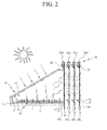
FIG. 2 is a front cross-sectional view ofFIG. 1 . -
FIG. 3 is a cross-sectional view of an effect stage according to the exemplary embodiment of the present invention. -
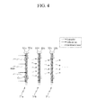
FIG. 4 is a cross-sectional view of an operation of a multi-effect distillation part according to the exemplary embodiment of the present invention. -
FIG. 5 is a schematic view of the multi-effect solar distiller according to the exemplary embodiment of the present invention. -
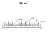
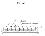
FIG. 6A to FIG. 6C are cross-sectional views of a shape of an absorption reflector according to the exemplary embodiment of the present invention. - Prior to describing several exemplary embodiments of the present invention in detail, it may be appreciated that applications of the exemplary embodiments of the present invention are not limited to details of configurations and arrangements of components described in the following detailed description or illustrated in the drawings. The present invention may be implemented and practiced as other exemplary embodiments and may be performed by various methods. Further, in connection with terms such as apparatus or element directions (for example, "front", "back", "up", "down", "top", "bottom", "left", "right", and "lateral") and the like, expressions and predicates which are used in the present application are only used to simplify the description of the present invention, and it may be appreciated that the related apparatuses or elements indicate or do not simply mean having a specific direction. Further, terms such as "first" and "second" are used in the present application for description and in the appended claims and do not indicate or mean relative importance or purpose.
- The present invention features to achieve the above objects as follows.
- Hereinafter, exemplary embodiments of the present invention will be described in detail with reference to the accompanying drawings. Terms and words used in the present specification and claims are not to be construed as a general or dictionary meaning, but are to be construed as meaning and concepts meeting the technical ideas of the present invention based on a principle that the present inventors may appropriately define the concepts of terms in order to describe their inventions in best modes.
- Therefore, the configurations described in the exemplary embodiments and drawings of the present invention are merely most preferable embodiments, but do not represent all of the technical spirit of the present invention. Thus, the present invention should be construed as including all changes, equivalents, and substitutions included in the spirit and scope of the present invention at the time of filing this application.
- Hereinafter, a multi-effect solar distiller with multiple heat sources according to an exemplary embodiment of the present invention will be described with reference to
FIGS. 1 to 6 . - As illustrated, a multi-effect
solar distiller 100 with multiple heat sources according to an exemplary embodiment of the present invention includes a solar thermal energy stillpart 10,absorption reflectors 20, and amulti-effect distillation part 30. - The solar thermal energy still part 10 heats sea water using solar thermal energy, and when the evaporated sea water is condensed, collects the condensed sea water, and is configured to include a sea
water storage tank 11, atransparent body 12, and a fresh water collectionopen channel 13. - The sea
water storage tank 11 stores sea water at a bottom surface within the solar thermal energy stillpart 10. - The
transparent body 12 has a shape such that it is installed to be spaced apart from an upper portion of the seawater storage tank 11, it is tilted by a predetermined angle in one direction to be longitudinally tilted downward, and is made of a transparent material (e.g. glass and the like) which may transmit sunlight (solar radiation energy) to evaporate sea water within the seawater storage tank 11. - In addition, according to the embodiment of the invention, a tilt angle α of the
transparent body 12 may be variously controlled depending on season, latitude, and the like of a target area where the multi-effect solar distiller with multiple heat sources according to the exemplary embodiment of the present invention is installed. - The fresh water collection
open channel 13 is longitudinally installed at one side of the seawater storage tank 11 within the solar thermal energy stillpart 10, the sea water of the seawater storage tank 11 is heated by sunlight transmitted through thetransparent body 12, and the heated sea water becomes steam and thus is formed at a lower surface of thetransparent body 12 in a water drop form. Next, condensed water having the water drop form flows down toward the one side of the transparent body which is tilted downward and thus is collected within the fresh water collectionopen channel 13. - Further, the solar thermal energy still
part 10 may heat the sea water within the seawater storage tank 11 using waste heat of exhaust gas as a heat source by installing atube 14 in which the exhaust gas may flow within the seawater storage tank 11 in various forms such as a zigzag form and the like to discharge the exhaust gas from apower generation facility 50 in an area where the multi-effect solar distiller according to the exemplary embodiment of the present invention is installed to the outside through thetube 14. A configuration using the waste heat as a heat source assists the heat source for sea water distillation in a season when sunlight is low or distills sea water even at night when solar thermal energy may not be used. - Referring to
FIGS. 1 and2 , the plurality ofabsorption reflectors 20 are installed within the seawater storage tank 11 of the foregoing solar thermal energy stillpart 10 to be spaced apart from each other at a predetermined interval, and have a form in which one end of theabsorption reflector 20 protrudes over a sea water level within the seawater storage tank 11. - In the case of sunlight which transmits through the
transparent body 12 and is incident on the seawater storage tank 11, since a loss of incident energy is high due to reflection from the sea water surface of the seawater storage tank 11, according to the exemplary embodiment of the present invention, the plurality ofabsorption reflectors 20 are installed within the seawater storage tank 11 to maximally use heat energy of the sunlight. - That is, the plurality of
absorption reflectors 20 are installed upright within the seawater storage tank 11 and the one end thereof protrudes over the sea water surface, such that the sunlight reflected from the sea water surface impinges on the one surface of theabsorption reflector 20, thereby heating theabsorption reflector 20. That is, theabsorption reflector 20 is heated with the light reflected from the sea water surface and may serve to additionally heat the sea water when theabsorption reflector 20 is heated. - Meanwhile, the
absorption reflector 20 may be coupled with one side of thetube 14. Theabsorption reflector 20 contacts thetube 14 to deliver the heat of the exhaust gas inside thetube 14 to the sea water through theabsorption reflector 20. Thereby, the heat source of the exhaust gas may be effectively used to heat the sea water. - In this case, the
absorption reflector 20 may have a plate shape. However, the shape of theabsorption reflector 20 is not limited thereto, and may be formed to have various shapes having a large cross-section which may effectively deliver the heat of the exhaust gas to the sea water. - Referring to
FIGS. 6A to 6C , according to the embodiment of the user, one end of the plurality ofabsorption reflectors 20 protruding over the sea water is bent toward the sea water at a predetermined angle to form abent part 21. In this case, the user coats one surface A of the one end facing the sea water black and coats the other surface thereof white to absorb the heat energy of a portion of the sunlight reflected from the sea water surface to the black coated surface and reflect sunlight incident to the white coated surface B of thebent part 21. And the sunlight reflected from the white coated surface B may be used as the heat source heating a front surface of afirst effect stage 31 a of themulti-effect distillation part 30 to be described below. - Further, the
first effect stage 31 a is heated by the solar radiation energy incident on the front surface, and a bend angle β of thebent part 21 may be controlled. - According to another exemplary embodiment of the user, each end of the plurality of
absorption reflectors 20 protrudes over the sea water level of the seawater storage tank 11 but lengths of protruding ends are different, thereby increasing the absorption and reflection effect. This may be applied to a form in which the one end is not bent or a form in which one end is bent. - The
multi-effect distillation part 30 is used to distill the sea water by the condensation heat of the sea water by installing a plurality of effect stages 31 upright at one side of the solar thermal energy still part 10 (or the other side of the sea water storage tank 11) so as to be spaced apart from each other by a predetermined interval. - Referring to
FIG. 1 , for convenience of explanation, aneffect stage 31 which is first installed to be adjacent to the solar thermal energy stillpart 10 is referred to as thefirst effect stage 31a and other effect stages 31 which are sequentially installed at one side of thefirst effect stage 31 a are referred to as asecond effect stage 31 b, athird effect stage 31 c, afourth effect stage 31 d, etc. - Referring to
FIG. 3 , each of the plurality of effect stages 31 is configured of aplate 32 andwicks 35. - The
plate 32 is installed upright on the ground and an upper end of a front side thereof is provided with asea water pocket 33 in which the sea water stored in asea water tank 40 may be supplied and stored by a seawater distribution tank 41, and a lower end of the front side thereof is provided with acondensation water pocket 34 in which condensed fresh water may be collected and stored. - The
wicks 35 are each attached on a rear surface of theplate 32 of eacheffect stage 31 and a top end of thewick 35 is bent to be dipped in thesea water pocket 33 of theplate 32, and thewick 35 has a structure such that it absorbs sea water of thesea water pocket 33 by surface tension to make the sea water flow in a length direction thereof. - Hereafter, an operation of a plurality of effect stages (for example, the first, second, third, fourth stages effect stages 31 a , 31 b, 31 c, and 31 d) having the foregoing structure will be described.
- In the case of the
first effect stage 31a which is first installed, being adjacent to the solar thermal energy stillpart 10, the sea water evaporated by the solar thermal energy at the solar thermal energy still part 10 (in more detail, the sea water storage tank 11) is condensed at the bottom surface of thetransparent body 12 and the front surface of thefirst effect stage 31 a and afirst stage plate 32a is vertically installed, and therefore the condensation water (fresh water) flows down to a lower end while being condensed at the front surface along thefirst stage plate 32a to be stored and collected in thecondensation water pocket 34. - Further, as described above, condensation latent heat which is generated when the sea water of the sea
water storage tank 11 is evaporated and then condensed at the front surface of thefirst stage plate 32a is conducted to afirst stage wick 35a through thefirst stage plate 32a to heat the sea water flowing in thefirst stage wick 35a, and the solar energy is used as an additional heat source required to heat the sea water flowing in thefirst stage wick 35a to absorb the solar thermal energy incident through thetransparent body 12 onto the front surface of thefirst stage plate 32a (according to the exemplary embodiment of the invention, the front surface of thefirst stage plate 32a is coated black to increase absorptance). The steam evaporated by thefirst stage wick 35a is condensed at the front surface of an adjacentsecond stage plate 32b by steam diffusion and thus flows down. - In this case, the condensation latent heat generated at the front surface of the
second stage plate 32b is conducted to asecond stage wick 35b through thesecond stage plate 32b and is used as a heat source for heating the sea water flowing along thesecond stage wick 35b. In this case, the sea water heated by thesecond stage wick 35b is again evaporated and is condensed at a front surface of an adjacentthird stage plate 32c by steam diffusion, and the condensation latent heat is conducted to the heating heat source of athird stage wick 35c. The process of condensation, conduction, evaporation, diffusion, and condensation as described above is repeatedly performed even in the following stages and thus theoretically, themulti-effect distillation part 30 has a structure in which eacheffect stage 31 repeatedly recovers the condensation heat until the wall surface temperature of theplate 32 reaches external temperature. - The exemplary embodiment of the present invention illustrates only a form in which a total of four
effect stages 31 up to afourth effect stage 31d configured of afourth stage plate 32d and afourth stage wick 35d are formed, but it may be appreciated that the number of stages of the installedplate 32 may be reduced or increased in consideration of a total heat value (solar radiation energy and condensation latent heat) absorbed into thefirst stage plate 32a, the sea water temperature, mass flow, the external temperature, and the like. - In addition, the residual sea water remaining after being evaporated while the sea water flows through the
wick 35 of themulti-effect distillation part 30 flows in a bottom end of thewick 35 and is discharged to the outside. - Reference 'V' in the drawing which is not described above is a mass flow controller (MFC) (for example, a mass control valve), and may control an amount of sea water supplied to the sea
water storage tank 11 of the solar thermal energy stillpart 10 and the sea water pockets 33 of each of the plurality of effect stages 31. 'S' represents the sea water, 'C' represents the condensation water, and 'B' represents the residual sea water remaining after evaporation. - While this invention has been described in connection with what is presently considered to be practical exemplary embodiments, it is to be understood that the invention is not limited to the disclosed embodiments, but, on the contrary, is intended to cover various modifications and equivalent arrangements included within the spirit and scope of the appended claims.
<Description of symbols> 10: Solar thermal energy still part 11: Sea water storage tank 12: Transparent body 13: Fresh water collection open channel 14: tube 20: Absorption reflector 21: Bent part 30: Multi-effect distillation part 31: Effect stage 31a: First effect stage 31b: Second effect stage 31c: Third effect stage 31d: Fourth effect stage 32: Plate 32a: First stage plate 32b: Second stage plate 33c: Third stage plate 33d: Fourth stage plate 33: Sea water pocket 34: Condensation water pocket 35: Wick 35a: First stage wick 35b: Second stage wick 35c: Third stage wick 35d: Fourth stage wick 40: Sea water tank 41: Sea water distribution tank 50: Power generation facility 51: Watt-hour meter
Claims (11)
- A multi-effect solar distiller with multiple heat sources, comprising:a solar thermal energy still part configured to evaporate sea water using solar thermal energy as a heat source to collect condensed fresh water;a plurality of absorption reflectors configured to be installed within the solar thermal energy still part to absorb and reflect solar thermal energy; anda multi-effect distillation part configured to condense steam generated from the solar thermal energy still part to collect fresh water and evaporate the sea water using condensation latent heat of the steam as a heat source to collect the fresh water.
- The multi-effect solar distiller of claim 1, wherein
the solar thermal energy still part
includes a tube configured to be installed within a sea water storage tank storing the sea water to use waste heat so as to evaporate the sea water and have exhaust gas flowing therein. - The multi-effect solar distiller of claim 2, wherein
the absorption reflector is coupled with one side of the tube. - The multi-effect solar distiller of claim 3, wherein
the absorption reflector has a plate shape. - The multi-effect solar distiller of claim 1, wherein
the absorption reflector
is installed within a sea water storage tank which is installed within the solar thermal energy still part and stores the sea water, and has one end protruding toward a sea water surface to absorb heat of sunlight reflected from the sea water surface. - The multi-effect solar distiller of claim 5, wherein
the one end of the absorption reflector is bent to form a predetermined angle with respect to the sea water surface, and a bend angle formed by the one end is controlled. - The multi-effect solar distiller of claim 5, wherein
the absorption reflector is installed in plural, and
ends of the plurality of absorption reflectors have different lengths. - The multi-effect solar distiller of claim 6, wherein
the absorption reflector
has one surface corresponding to the sea water level absorbing heat of sunlight and the other surface reflecting sunlight toward the multi-effect distillation part. - The multi-effect solar distiller of claim 1, wherein
the multi-effect distillation part has a plurality of effect stages which are disposed to be spaced apart from each other, and
each of the plurality of effect stages includes:a plate configured to be provided with a sea water pocket of which one surface of an upper side is filled with the sea water and a condensation water pocket of which one surface of a lower side collects condensation water; anda wick configured to be attached to a rear surface of the plate to draw the sea water from the sea water pocket and cause the drawn sea water to flow. - The multi-effect solar distiller of claim 9, wherein:in a first effect stage nearest to the solar thermal energy still part among the plurality of effect stages, the steam evaporated by the solar thermal energy still part is condensed at a front surface of the plate of the first effect stage and is stored in the condensation water pocket of the first effect stage; andthe sea water flowing in the wick of the first effect stage is heated by the condensation latent heat of the steam and solar radiation energy incident on the one side of the plate of the first effect stage.
- The multi-effect solar distiller of claim 10, wherein:in the remaining effect stages continuously installed corresponding to the first effect stage among the plurality of effect stages, the condensation water formed at the front surfaces of each plate of the remaining effect stages is stored in each condensation water pocket of the remaining effect stages; andthe sea water flowing in each wick of the remaining effect stages is evaporated by the condensation latent heat of the condensation water and the evaporated steam is condensed at a front surface of a plate of a next adjacent effect stage by diffusion.
Applications Claiming Priority (2)
| Application Number | Priority Date | Filing Date | Title |
|---|---|---|---|
| KR20120064869A KR101425415B1 (en) | 2012-06-18 | 2012-06-18 | Ambient pressure type Multi Effect Distiller using Solar Thermal Energy and Multiple Heat Source |
| PCT/KR2013/003253 WO2013191362A1 (en) | 2012-06-18 | 2013-04-17 | Normal pressure-type multiple-effect desalination device using solar heat and multiple heat sources |
Publications (3)
| Publication Number | Publication Date |
|---|---|
| EP2862842A1 true EP2862842A1 (en) | 2015-04-22 |
| EP2862842A4 EP2862842A4 (en) | 2015-11-11 |
| EP2862842B1 EP2862842B1 (en) | 2017-09-06 |
Family
ID=49768931
Family Applications (1)
| Application Number | Title | Priority Date | Filing Date |
|---|---|---|---|
| EP13807432.3A Active EP2862842B1 (en) | 2012-06-18 | 2013-04-17 | Normal pressure-type multiple-effect desalination device using solar heat and multiple heat sources |
Country Status (7)
| Country | Link |
|---|---|
| US (1) | US9884265B2 (en) |
| EP (1) | EP2862842B1 (en) |
| KR (1) | KR101425415B1 (en) |
| ES (1) | ES2645976T3 (en) |
| PT (1) | PT2862842T (en) |
| SG (1) | SG11201408477PA (en) |
| WO (1) | WO2013191362A1 (en) |
Cited By (3)
| Publication number | Priority date | Publication date | Assignee | Title |
|---|---|---|---|---|
| EA035985B1 (en) * | 2019-05-22 | 2020-09-09 | Федеральное государственное бюджетное образовательное учреждение высшего образования "Юго-Западный государственный университет" (ЮЗГУ) | Self-contained solar-thermal electric desalination plant |
| RU2768909C2 (en) * | 2020-05-28 | 2022-03-25 | Федеральное государственное бюджетное образовательное учреждение высшего образования "Юго-Западный государственный университет" (ЮЗГУ) | Autonomous self-orienting solar desalter-electric generator |
| FR3148789A1 (en) | 2023-05-18 | 2024-11-22 | Christophe HUGON | Floating desalination and pollution control modules powered by solar heat |
Families Citing this family (22)
| Publication number | Priority date | Publication date | Assignee | Title |
|---|---|---|---|---|
| KR101667106B1 (en) * | 2014-08-01 | 2016-10-28 | 장준형 | Amphibious support type water distillation generator |
| KR101582987B1 (en) * | 2014-09-03 | 2016-01-07 | 주식회사 프로세이브 | Desalination apparatus of sea water having solar panel |
| KR101627454B1 (en) * | 2015-02-25 | 2016-06-08 | 한양대학교 에리카산학협력단 | Water treatment system |
| KR101757357B1 (en) * | 2015-05-22 | 2017-07-12 | 한국기계연구원 | Desalination apparatus including wickless plate |
| KR101888631B1 (en) | 2016-04-06 | 2018-08-14 | 한국기계연구원 | Apparatus for desalination using solar heat |
| KR102715914B1 (en) | 2016-04-07 | 2024-10-11 | 주식회사 스토익엔터테인먼트 | system for implementing 3-D virtual reality |
| KR101721203B1 (en) * | 2016-05-31 | 2017-03-29 | 한국기계연구원 | Desalination apparatus using solar thermal energy and waste heat |
| AU2017368233A1 (en) * | 2016-11-30 | 2019-07-11 | The Research Foundation For The State University Of New York | System and method for solar vapor evaporation and condensation |
| KR101895462B1 (en) * | 2016-12-14 | 2018-09-06 | 김민호 | seawater desalinnation device using solar and waste heat, and bay salt manufacturing device |
| US11312640B2 (en) * | 2017-10-30 | 2022-04-26 | King Abdullah University Of Science And Technology | Method and device for enhanced water production in solar-powered devices |
| KR20210037306A (en) | 2019-09-27 | 2021-04-06 | 한국기계연구원 | Multiple desalination apparatus using thermal radiation and process heat |
| CN111547801A (en) * | 2020-04-14 | 2020-08-18 | 西安理工大学 | Concentrated water photothermal evaporation treatment device for brackish water desalination and treatment method thereof |
| CN112125367A (en) * | 2020-09-02 | 2020-12-25 | 清华大学 | Clean water production device and production method |
| CN112479294B (en) * | 2020-11-27 | 2025-05-23 | 浙江浙能技术研究院有限公司 | A multi-stage inclined floating solar seawater desalination distiller and method |
| CN113023813B (en) * | 2021-05-07 | 2022-07-01 | 北京理工大学 | Self-irrigation marine floating type planting device based on solar distillation |
| CN113443672A (en) * | 2021-06-17 | 2021-09-28 | 浙江大学 | Solar-driven multistage seawater desalination device |
| CN113968599B (en) * | 2021-09-30 | 2023-06-20 | 中北大学 | An integrated solar interface evaporation device |
| CN115215401A (en) * | 2022-07-22 | 2022-10-21 | 中国科学技术大学 | Distillation device for solar saline water desalination |
| CN117623428B (en) * | 2023-10-31 | 2025-09-19 | 同济大学 | Metal-based interface evaporator suitable for high-salinity water treatment |
| CN117326616B (en) * | 2023-11-07 | 2025-11-11 | 清华大学深圳国际研究生院 | Multistage solar evaporator based on reverse distillation |
| CN118026326A (en) * | 2024-01-18 | 2024-05-14 | 河海大学 | Solar thermal still insensitive to incident angle |
| US12246973B1 (en) | 2024-05-16 | 2025-03-11 | Kuwait University | Solar still water treatment using carbon-based effervescent tablets and related methods |
Family Cites Families (6)
| Publication number | Priority date | Publication date | Assignee | Title |
|---|---|---|---|---|
| US4850338A (en) * | 1981-08-28 | 1989-07-25 | Husson Jr Frank D | Solar collector system with radiation concentrated on heat absorber vanes |
| JPH11156341A (en) * | 1997-11-26 | 1999-06-15 | Top Ecology:Kk | Solar thermal distillator |
| US20040060808A1 (en) * | 2000-08-09 | 2004-04-01 | Laviolette Paul Alex | Advective solar collector for use in multi-effect fluid distillation and power co-generation |
| JP2005224699A (en) * | 2004-02-12 | 2005-08-25 | Kozaburo Miyazaki | Water purification apparatus |
| KR101084305B1 (en) * | 2009-03-30 | 2011-11-16 | 한국기계연구원 | Desalination System Using Waste Heat and Desalination Method |
| KR101134421B1 (en) * | 2009-11-05 | 2012-04-09 | 한국기계연구원 | Multi Effect Distiller using Solar Thermal Energy |
-
2012
- 2012-06-18 KR KR20120064869A patent/KR101425415B1/en active Active
-
2013
- 2013-04-17 WO PCT/KR2013/003253 patent/WO2013191362A1/en not_active Ceased
- 2013-04-17 US US14/408,376 patent/US9884265B2/en active Active
- 2013-04-17 SG SG11201408477PA patent/SG11201408477PA/en unknown
- 2013-04-17 EP EP13807432.3A patent/EP2862842B1/en active Active
- 2013-04-17 PT PT138074323T patent/PT2862842T/en unknown
- 2013-04-17 ES ES13807432.3T patent/ES2645976T3/en active Active
Cited By (3)
| Publication number | Priority date | Publication date | Assignee | Title |
|---|---|---|---|---|
| EA035985B1 (en) * | 2019-05-22 | 2020-09-09 | Федеральное государственное бюджетное образовательное учреждение высшего образования "Юго-Западный государственный университет" (ЮЗГУ) | Self-contained solar-thermal electric desalination plant |
| RU2768909C2 (en) * | 2020-05-28 | 2022-03-25 | Федеральное государственное бюджетное образовательное учреждение высшего образования "Юго-Западный государственный университет" (ЮЗГУ) | Autonomous self-orienting solar desalter-electric generator |
| FR3148789A1 (en) | 2023-05-18 | 2024-11-22 | Christophe HUGON | Floating desalination and pollution control modules powered by solar heat |
Also Published As
| Publication number | Publication date |
|---|---|
| US9884265B2 (en) | 2018-02-06 |
| EP2862842A4 (en) | 2015-11-11 |
| WO2013191362A1 (en) | 2013-12-27 |
| PT2862842T (en) | 2017-10-02 |
| KR20130141843A (en) | 2013-12-27 |
| SG11201408477PA (en) | 2015-02-27 |
| KR101425415B1 (en) | 2014-07-31 |
| US20150209686A1 (en) | 2015-07-30 |
| EP2862842B1 (en) | 2017-09-06 |
| ES2645976T3 (en) | 2017-12-11 |
Similar Documents
| Publication | Publication Date | Title |
|---|---|---|
| EP2862842B1 (en) | Normal pressure-type multiple-effect desalination device using solar heat and multiple heat sources | |
| Compain | Solar energy for water desalination | |
| KR101425414B1 (en) | Multi Effect Distiller with hydrophilic plate using Solar Thermal Energy | |
| KR101702850B1 (en) | Solar desalination modules for stand-alone | |
| Zayed et al. | Optimal configuration of a semi-corrugated basin with inverted solar concentrator for performance augmentation of hemispherical shaped solar distiller: a comparative experimental investigation | |
| KR101134421B1 (en) | Multi Effect Distiller using Solar Thermal Energy | |
| US9289696B2 (en) | Water desalination system using geothermal energy | |
| Maftouh et al. | Solar desalination: Current applications and future potential in MENA region–A case study | |
| KR101218131B1 (en) | Ambient pressure type multi-effect distiller using solar thermal energy and waste heat | |
| US20060168960A1 (en) | Machine and system for solar power generation | |
| Rashid et al. | Inventive tubular solar stills: improving desalination performance through phase change materials and upgraded design for sustainable water solutions | |
| US20160233829A1 (en) | Solar water-collecting, air-conditioning, light-transmitting and power generating house | |
| CN113501557A (en) | Solar water dispenser based on honeycomb bionic evaporator | |
| Baker et al. | Performance comparison of solar stills using two kinds of solar collectors | |
| KR101232829B1 (en) | Simultaneous producing system of electric power and distilled water | |
| KR101425413B1 (en) | Multi Effect Distiller with transparent plate using Solar Thermal Energy | |
| JP5075916B2 (en) | Solar heat utilization system | |
| CN215439746U (en) | A solar water dispenser based on honeycomb bionic evaporator | |
| CN102326033B (en) | Simultaneous drinking water/hot water recovery-type solar water-heating device | |
| Alanezi et al. | A novel hybrid compact system of photovoltaic solar still air gap membrane distillation for the simultaneous production of water and energy | |
| WO2016001369A1 (en) | System of a desalination plant driven by a solar power plant | |
| KR101721203B1 (en) | Desalination apparatus using solar thermal energy and waste heat | |
| Hilarydoss | A detailed review on various aspects of inverted solar still desalination systems proposed for clean water production | |
| Malaiyappan et al. | Review of the productivity of various types of solar stills | |
| Pathak et al. | Role of solar energy applications for environmental sustainability |
Legal Events
| Date | Code | Title | Description |
|---|---|---|---|
| PUAI | Public reference made under article 153(3) epc to a published international application that has entered the european phase |
Free format text: ORIGINAL CODE: 0009012 |
|
| 17P | Request for examination filed |
Effective date: 20141222 |
|
| AK | Designated contracting states |
Kind code of ref document: A1 Designated state(s): AL AT BE BG CH CY CZ DE DK EE ES FI FR GB GR HR HU IE IS IT LI LT LU LV MC MK MT NL NO PL PT RO RS SE SI SK SM TR |
|
| AX | Request for extension of the european patent |
Extension state: BA ME |
|
| DAX | Request for extension of the european patent (deleted) | ||
| RA4 | Supplementary search report drawn up and despatched (corrected) |
Effective date: 20151014 |
|
| RIC1 | Information provided on ipc code assigned before grant |
Ipc: C02F 1/14 20060101AFI20151008BHEP Ipc: B01D 1/00 20060101ALI20151008BHEP Ipc: C02F 1/04 20060101ALI20151008BHEP |
|
| 17Q | First examination report despatched |
Effective date: 20160922 |
|
| GRAP | Despatch of communication of intention to grant a patent |
Free format text: ORIGINAL CODE: EPIDOSNIGR1 |
|
| INTG | Intention to grant announced |
Effective date: 20170324 |
|
| GRAS | Grant fee paid |
Free format text: ORIGINAL CODE: EPIDOSNIGR3 |
|
| GRAA | (expected) grant |
Free format text: ORIGINAL CODE: 0009210 |
|
| AK | Designated contracting states |
Kind code of ref document: B1 Designated state(s): AL AT BE BG CH CY CZ DE DK EE ES FI FR GB GR HR HU IE IS IT LI LT LU LV MC MK MT NL NO PL PT RO RS SE SI SK SM TR |
|
| REG | Reference to a national code |
Ref country code: GB Ref legal event code: FG4D |
|
| REG | Reference to a national code |
Ref country code: CH Ref legal event code: EP Ref country code: AT Ref legal event code: REF Ref document number: 925678 Country of ref document: AT Kind code of ref document: T Effective date: 20170915 |
|
| REG | Reference to a national code |
Ref country code: PT Ref legal event code: SC4A Ref document number: 2862842 Country of ref document: PT Date of ref document: 20171002 Kind code of ref document: T Free format text: AVAILABILITY OF NATIONAL TRANSLATION Effective date: 20170919 |
|
| REG | Reference to a national code |
Ref country code: IE Ref legal event code: FG4D |
|
| REG | Reference to a national code |
Ref country code: DE Ref legal event code: R096 Ref document number: 602013026295 Country of ref document: DE |
|
| REG | Reference to a national code |
Ref country code: ES Ref legal event code: FG2A Ref document number: 2645976 Country of ref document: ES Kind code of ref document: T3 Effective date: 20171211 |
|
| REG | Reference to a national code |
Ref country code: NL Ref legal event code: MP Effective date: 20170906 |
|
| REG | Reference to a national code |
Ref country code: LT Ref legal event code: MG4D |
|
| PG25 | Lapsed in a contracting state [announced via postgrant information from national office to epo] |
Ref country code: NO Free format text: LAPSE BECAUSE OF FAILURE TO SUBMIT A TRANSLATION OF THE DESCRIPTION OR TO PAY THE FEE WITHIN THE PRESCRIBED TIME-LIMIT Effective date: 20171206 Ref country code: SE Free format text: LAPSE BECAUSE OF FAILURE TO SUBMIT A TRANSLATION OF THE DESCRIPTION OR TO PAY THE FEE WITHIN THE PRESCRIBED TIME-LIMIT Effective date: 20170906 Ref country code: FI Free format text: LAPSE BECAUSE OF FAILURE TO SUBMIT A TRANSLATION OF THE DESCRIPTION OR TO PAY THE FEE WITHIN THE PRESCRIBED TIME-LIMIT Effective date: 20170906 Ref country code: LT Free format text: LAPSE BECAUSE OF FAILURE TO SUBMIT A TRANSLATION OF THE DESCRIPTION OR TO PAY THE FEE WITHIN THE PRESCRIBED TIME-LIMIT Effective date: 20170906 Ref country code: HR Free format text: LAPSE BECAUSE OF FAILURE TO SUBMIT A TRANSLATION OF THE DESCRIPTION OR TO PAY THE FEE WITHIN THE PRESCRIBED TIME-LIMIT Effective date: 20170906 |
|
| REG | Reference to a national code |
Ref country code: AT Ref legal event code: MK05 Ref document number: 925678 Country of ref document: AT Kind code of ref document: T Effective date: 20170906 |
|
| PG25 | Lapsed in a contracting state [announced via postgrant information from national office to epo] |
Ref country code: BG Free format text: LAPSE BECAUSE OF FAILURE TO SUBMIT A TRANSLATION OF THE DESCRIPTION OR TO PAY THE FEE WITHIN THE PRESCRIBED TIME-LIMIT Effective date: 20171206 Ref country code: LV Free format text: LAPSE BECAUSE OF FAILURE TO SUBMIT A TRANSLATION OF THE DESCRIPTION OR TO PAY THE FEE WITHIN THE PRESCRIBED TIME-LIMIT Effective date: 20170906 Ref country code: RS Free format text: LAPSE BECAUSE OF FAILURE TO SUBMIT A TRANSLATION OF THE DESCRIPTION OR TO PAY THE FEE WITHIN THE PRESCRIBED TIME-LIMIT Effective date: 20170906 Ref country code: GR Free format text: LAPSE BECAUSE OF FAILURE TO SUBMIT A TRANSLATION OF THE DESCRIPTION OR TO PAY THE FEE WITHIN THE PRESCRIBED TIME-LIMIT Effective date: 20171207 |
|
| PG25 | Lapsed in a contracting state [announced via postgrant information from national office to epo] |
Ref country code: NL Free format text: LAPSE BECAUSE OF FAILURE TO SUBMIT A TRANSLATION OF THE DESCRIPTION OR TO PAY THE FEE WITHIN THE PRESCRIBED TIME-LIMIT Effective date: 20170906 |
|
| PG25 | Lapsed in a contracting state [announced via postgrant information from national office to epo] |
Ref country code: PL Free format text: LAPSE BECAUSE OF FAILURE TO SUBMIT A TRANSLATION OF THE DESCRIPTION OR TO PAY THE FEE WITHIN THE PRESCRIBED TIME-LIMIT Effective date: 20170906 Ref country code: CZ Free format text: LAPSE BECAUSE OF FAILURE TO SUBMIT A TRANSLATION OF THE DESCRIPTION OR TO PAY THE FEE WITHIN THE PRESCRIBED TIME-LIMIT Effective date: 20170906 Ref country code: RO Free format text: LAPSE BECAUSE OF FAILURE TO SUBMIT A TRANSLATION OF THE DESCRIPTION OR TO PAY THE FEE WITHIN THE PRESCRIBED TIME-LIMIT Effective date: 20170906 |
|
| PG25 | Lapsed in a contracting state [announced via postgrant information from national office to epo] |
Ref country code: EE Free format text: LAPSE BECAUSE OF FAILURE TO SUBMIT A TRANSLATION OF THE DESCRIPTION OR TO PAY THE FEE WITHIN THE PRESCRIBED TIME-LIMIT Effective date: 20170906 Ref country code: SK Free format text: LAPSE BECAUSE OF FAILURE TO SUBMIT A TRANSLATION OF THE DESCRIPTION OR TO PAY THE FEE WITHIN THE PRESCRIBED TIME-LIMIT Effective date: 20170906 Ref country code: AT Free format text: LAPSE BECAUSE OF FAILURE TO SUBMIT A TRANSLATION OF THE DESCRIPTION OR TO PAY THE FEE WITHIN THE PRESCRIBED TIME-LIMIT Effective date: 20170906 Ref country code: SM Free format text: LAPSE BECAUSE OF FAILURE TO SUBMIT A TRANSLATION OF THE DESCRIPTION OR TO PAY THE FEE WITHIN THE PRESCRIBED TIME-LIMIT Effective date: 20170906 Ref country code: IS Free format text: LAPSE BECAUSE OF FAILURE TO SUBMIT A TRANSLATION OF THE DESCRIPTION OR TO PAY THE FEE WITHIN THE PRESCRIBED TIME-LIMIT Effective date: 20180106 |
|
| REG | Reference to a national code |
Ref country code: DE Ref legal event code: R097 Ref document number: 602013026295 Country of ref document: DE |
|
| PLBE | No opposition filed within time limit |
Free format text: ORIGINAL CODE: 0009261 |
|
| STAA | Information on the status of an ep patent application or granted ep patent |
Free format text: STATUS: NO OPPOSITION FILED WITHIN TIME LIMIT |
|
| PG25 | Lapsed in a contracting state [announced via postgrant information from national office to epo] |
Ref country code: DK Free format text: LAPSE BECAUSE OF FAILURE TO SUBMIT A TRANSLATION OF THE DESCRIPTION OR TO PAY THE FEE WITHIN THE PRESCRIBED TIME-LIMIT Effective date: 20170906 |
|
| 26N | No opposition filed |
Effective date: 20180607 |
|
| PG25 | Lapsed in a contracting state [announced via postgrant information from national office to epo] |
Ref country code: SI Free format text: LAPSE BECAUSE OF FAILURE TO SUBMIT A TRANSLATION OF THE DESCRIPTION OR TO PAY THE FEE WITHIN THE PRESCRIBED TIME-LIMIT Effective date: 20170906 |
|
| REG | Reference to a national code |
Ref country code: DE Ref legal event code: R119 Ref document number: 602013026295 Country of ref document: DE |
|
| PG25 | Lapsed in a contracting state [announced via postgrant information from national office to epo] |
Ref country code: MC Free format text: LAPSE BECAUSE OF FAILURE TO SUBMIT A TRANSLATION OF THE DESCRIPTION OR TO PAY THE FEE WITHIN THE PRESCRIBED TIME-LIMIT Effective date: 20170906 |
|
| REG | Reference to a national code |
Ref country code: CH Ref legal event code: PL |
|
| REG | Reference to a national code |
Ref country code: BE Ref legal event code: MM Effective date: 20180430 |
|
| GBPC | Gb: european patent ceased through non-payment of renewal fee |
Effective date: 20180417 |
|
| REG | Reference to a national code |
Ref country code: IE Ref legal event code: MM4A |
|
| PG25 | Lapsed in a contracting state [announced via postgrant information from national office to epo] |
Ref country code: DE Free format text: LAPSE BECAUSE OF NON-PAYMENT OF DUE FEES Effective date: 20181101 Ref country code: LU Free format text: LAPSE BECAUSE OF NON-PAYMENT OF DUE FEES Effective date: 20180417 |
|
| PG25 | Lapsed in a contracting state [announced via postgrant information from national office to epo] |
Ref country code: GB Free format text: LAPSE BECAUSE OF NON-PAYMENT OF DUE FEES Effective date: 20180417 Ref country code: LI Free format text: LAPSE BECAUSE OF NON-PAYMENT OF DUE FEES Effective date: 20180430 Ref country code: CH Free format text: LAPSE BECAUSE OF NON-PAYMENT OF DUE FEES Effective date: 20180430 Ref country code: BE Free format text: LAPSE BECAUSE OF NON-PAYMENT OF DUE FEES Effective date: 20180430 |
|
| PG25 | Lapsed in a contracting state [announced via postgrant information from national office to epo] |
Ref country code: IE Free format text: LAPSE BECAUSE OF NON-PAYMENT OF DUE FEES Effective date: 20180417 Ref country code: FR Free format text: LAPSE BECAUSE OF NON-PAYMENT OF DUE FEES Effective date: 20180430 |
|
| PG25 | Lapsed in a contracting state [announced via postgrant information from national office to epo] |
Ref country code: MT Free format text: LAPSE BECAUSE OF NON-PAYMENT OF DUE FEES Effective date: 20180417 |
|
| PG25 | Lapsed in a contracting state [announced via postgrant information from national office to epo] |
Ref country code: TR Free format text: LAPSE BECAUSE OF FAILURE TO SUBMIT A TRANSLATION OF THE DESCRIPTION OR TO PAY THE FEE WITHIN THE PRESCRIBED TIME-LIMIT Effective date: 20170906 |
|
| PG25 | Lapsed in a contracting state [announced via postgrant information from national office to epo] |
Ref country code: HU Free format text: LAPSE BECAUSE OF FAILURE TO SUBMIT A TRANSLATION OF THE DESCRIPTION OR TO PAY THE FEE WITHIN THE PRESCRIBED TIME-LIMIT; INVALID AB INITIO Effective date: 20130417 Ref country code: MK Free format text: LAPSE BECAUSE OF NON-PAYMENT OF DUE FEES Effective date: 20170906 Ref country code: CY Free format text: LAPSE BECAUSE OF FAILURE TO SUBMIT A TRANSLATION OF THE DESCRIPTION OR TO PAY THE FEE WITHIN THE PRESCRIBED TIME-LIMIT Effective date: 20170906 |
|
| PG25 | Lapsed in a contracting state [announced via postgrant information from national office to epo] |
Ref country code: AL Free format text: LAPSE BECAUSE OF FAILURE TO SUBMIT A TRANSLATION OF THE DESCRIPTION OR TO PAY THE FEE WITHIN THE PRESCRIBED TIME-LIMIT Effective date: 20170906 |
|
| PGFP | Annual fee paid to national office [announced via postgrant information from national office to epo] |
Ref country code: ES Payment date: 20250508 Year of fee payment: 13 |
|
| PGFP | Annual fee paid to national office [announced via postgrant information from national office to epo] |
Ref country code: PT Payment date: 20250414 Year of fee payment: 13 |
|
| PGFP | Annual fee paid to national office [announced via postgrant information from national office to epo] |
Ref country code: IT Payment date: 20260320 Year of fee payment: 14 |