EP2862812A1 - Mehrkomponentenkartusche - Google Patents
Mehrkomponentenkartusche Download PDFInfo
- Publication number
- EP2862812A1 EP2862812A1 EP20140003467 EP14003467A EP2862812A1 EP 2862812 A1 EP2862812 A1 EP 2862812A1 EP 20140003467 EP20140003467 EP 20140003467 EP 14003467 A EP14003467 A EP 14003467A EP 2862812 A1 EP2862812 A1 EP 2862812A1
- Authority
- EP
- European Patent Office
- Prior art keywords
- container
- receiving sleeve
- component
- outlet section
- outlet
- Prior art date
- Legal status (The legal status is an assumption and is not a legal conclusion. Google has not performed a legal analysis and makes no representation as to the accuracy of the status listed.)
- Granted
Links
- 230000006378 damage Effects 0.000 abstract description 8
- 239000000203 mixture Substances 0.000 description 5
- 239000006228 supernatant Substances 0.000 description 5
- 238000003825 pressing Methods 0.000 description 4
- 239000004743 Polypropylene Substances 0.000 description 3
- 229920001684 low density polyethylene Polymers 0.000 description 3
- 239000004702 low-density polyethylene Substances 0.000 description 3
- 229920001155 polypropylene Polymers 0.000 description 3
- 230000006835 compression Effects 0.000 description 2
- 238000007906 compression Methods 0.000 description 2
- 238000010276 construction Methods 0.000 description 2
- 238000001746 injection moulding Methods 0.000 description 2
- 238000003780 insertion Methods 0.000 description 2
- 230000037431 insertion Effects 0.000 description 2
- 239000004570 mortar (masonry) Substances 0.000 description 2
- 239000004033 plastic Substances 0.000 description 2
- 229920003023 plastic Polymers 0.000 description 2
- -1 polypropylene Polymers 0.000 description 2
- 239000007787 solid Substances 0.000 description 2
- 208000027418 Wounds and injury Diseases 0.000 description 1
- 238000004026 adhesive bonding Methods 0.000 description 1
- 238000000071 blow moulding Methods 0.000 description 1
- 238000001125 extrusion Methods 0.000 description 1
- 208000014674 injury Diseases 0.000 description 1
- 238000004519 manufacturing process Methods 0.000 description 1
- 239000000463 material Substances 0.000 description 1
- 239000004848 polyfunctional curative Substances 0.000 description 1
- 230000001681 protective effect Effects 0.000 description 1
- 239000007779 soft material Substances 0.000 description 1
Images


Classifications
-
- B—PERFORMING OPERATIONS; TRANSPORTING
- B65—CONVEYING; PACKING; STORING; HANDLING THIN OR FILAMENTARY MATERIAL
- B65D—CONTAINERS FOR STORAGE OR TRANSPORT OF ARTICLES OR MATERIALS, e.g. BAGS, BARRELS, BOTTLES, BOXES, CANS, CARTONS, CRATES, DRUMS, JARS, TANKS, HOPPERS, FORWARDING CONTAINERS; ACCESSORIES, CLOSURES, OR FITTINGS THEREFOR; PACKAGING ELEMENTS; PACKAGES
- B65D81/00—Containers, packaging elements, or packages, for contents presenting particular transport or storage problems, or adapted to be used for non-packaging purposes after removal of contents
- B65D81/32—Containers, packaging elements, or packages, for contents presenting particular transport or storage problems, or adapted to be used for non-packaging purposes after removal of contents for packaging two or more different materials which must be maintained separate prior to use in admixture
- B65D81/325—Containers having parallel or coaxial compartments, provided with a piston or a movable bottom for discharging contents
-
- B—PERFORMING OPERATIONS; TRANSPORTING
- B65—CONVEYING; PACKING; STORING; HANDLING THIN OR FILAMENTARY MATERIAL
- B65D—CONTAINERS FOR STORAGE OR TRANSPORT OF ARTICLES OR MATERIALS, e.g. BAGS, BARRELS, BOTTLES, BOXES, CANS, CARTONS, CRATES, DRUMS, JARS, TANKS, HOPPERS, FORWARDING CONTAINERS; ACCESSORIES, CLOSURES, OR FITTINGS THEREFOR; PACKAGING ELEMENTS; PACKAGES
- B65D77/00—Packages formed by enclosing articles or materials in preformed containers, e.g. boxes, cartons, sacks or bags
- B65D77/08—Materials, e.g. different materials, enclosed in separate compartments formed during filling of a single container
-
- B—PERFORMING OPERATIONS; TRANSPORTING
- B65—CONVEYING; PACKING; STORING; HANDLING THIN OR FILAMENTARY MATERIAL
- B65D—CONTAINERS FOR STORAGE OR TRANSPORT OF ARTICLES OR MATERIALS, e.g. BAGS, BARRELS, BOTTLES, BOXES, CANS, CARTONS, CRATES, DRUMS, JARS, TANKS, HOPPERS, FORWARDING CONTAINERS; ACCESSORIES, CLOSURES, OR FITTINGS THEREFOR; PACKAGING ELEMENTS; PACKAGES
- B65D81/00—Containers, packaging elements, or packages, for contents presenting particular transport or storage problems, or adapted to be used for non-packaging purposes after removal of contents
- B65D81/32—Containers, packaging elements, or packages, for contents presenting particular transport or storage problems, or adapted to be used for non-packaging purposes after removal of contents for packaging two or more different materials which must be maintained separate prior to use in admixture
- B65D81/3233—Flexible containers disposed within rigid containers
- B65D81/3244—Flexible containers disposed within rigid containers arranged parallel or concentrically and permitting simultaneous dispensing of the two materials without prior mixing
Definitions
- the invention relates to a multi-component cartridge having the features of the preamble of claim 1.
- a generic multi-component cartridge is known.
- a first container encloses a second container. Both containers are provided for receiving components of a curable composition to be stored separately.
- the first container receives a mortar
- the second container contains the hardener of a two-component mortar composition.
- the two components are squeezed out of the cartridge by a piston, for example into a mixer screwed onto an external thread of the cartridge for mixing the components.
- the multi-component cartridge has an outlet section for dispensing the first component.
- the outlet of the second container is formed as a tubular outlet section, which is arranged in a receiving sleeve arranged centrally in the outlet section.
- the outlet section is closed by a closure cap.
- the closure cap is screwed onto the external thread of the cartridge. It may happen that residues of the components, which remain in an outlet opening of the outlet section, stick to the closure cap and the outlet section. If the cap is unscrewed again, the rotational movement is transmitted to the tubular and thin-walled outlet section by the adhesion, as a result of which it can be damaged and ruptures, so that a controlled delivery of the second component is no longer possible.
- the object of the invention is therefore to propose a multi-component cartridge, in which the outlet section is protected against damage during repeated twisting of the closure cap.
- the multi-component cartridge according to the invention is in particular a two-component cartridge.
- the multi-component cartridge according to the invention comprises a first container for receiving a first component and a second container for receiving a second component of a hardenable mass.
- further containers may be arranged on the multi-component cartridge.
- the containers can be pressed in particular with a piston of the multi-chamber cartridge.
- the multi-component cartridge has an outlet section with an outlet opening for dispensing the first component. In this outlet section, a receiving sleeve is arranged, in which an outlet section of the second container rests.
- “Inlaid” means here in particular that the outlet portion is received in the receiving sleeve and is held by it.
- the receiving sleeve is in particular immovable to and in particular in one piece with the outlet section.
- the outlet section is designed in particular cylindrical and tubular and has an outlet opening from which the second component can emerge from the second container.
- Characteristic of the multicomponent cartridge according to the invention is that the receiving sleeve protrudes beyond the outlet section in the outlet direction of the mass, wherein the supernatant is in particular not greater than 2 mm, in particular not greater than 1 mm. If the multicomponent cartridge is closed with a closure cap, then the front end of the receiving sleeve rests against the closure cap, in particular in such a way that the closure cap seals the front end of the receiving sleeve. This prevents that the two components of the curable composition, which are located in the outlet or outlet opening, come into contact with the cap screwed on, react with each other and harden when the multi-component cartridge is closed with a cap.
- the receiving sleeve overflows in the outlet direction of the mass via the outlet section, so that the outlet section is protected within the receiving sleeve.
- the supernatant may be several millimeters, but in particular not greater than 2 mm, in particular not greater than 1 mm.
- the receiving sleeve is arranged eccentrically in the outlet section. Due to the eccentric arrangement prevents the arranged in the receiving sleeve outlet portion is twisted when twisting the cap, so twisted, which would lead to large stresses in the outlet section. Due to the eccentric arrangement, essentially shear forces act on the outlet section, which are discharged to the receiving sleeve, whereby the stresses acting on the outlet section are significantly reduced. Thus, damage to the outlet portion during repeated twisting of the cap is practically impossible.
- Another advantage of the eccentric arrangement is that the pressing out of the first component is impeded to a much lesser extent by the receiving sleeve than is the case with the centric arrangement known from the prior art.
- the receiving sleeve is arranged on an inner wall of the outlet section.
- the receiving sleeve forms a part of the inner wall.
- This embodiment has the advantage that the receiving sleeve stable and without large. Effort can be arranged in the outlet section without unnecessarily narrowing their cross section through struts or webs. Due to the fact that the receiving sleeve forms part of the inner wall of the outlet section, additional gluing or mechanical connection of the receiving sleeve to the inner wall of the outlet section is not necessary.
- the receiving sleeve is formed as a cylindrical tube, which facilitates production of the receiving sleeve and mounting of the outlet portion in the receiving sleeve.
- the receiving sleeve has at its rear end an enlarged receiving opening, which facilitates insertion of the outlet section into the receiving sleeve.
- the receiving opening widens conically, in particular conically, to the rear. "Rear” here refers to the exit direction into which the components of the curable composition emerge from the outlet or outlet opening.
- Another embodiment of the multicomponent cartridge according to the invention is designed such that the outer wall of the outlet portion rests over the entire surface of the inner wall of the receiving sleeve.
- the outer wall of the outlet section rests against the inner wall of the receiving sleeve over its entire circumference, tightly and in particular by clamping, so that the outlet section is sealed in the circumferential direction with respect to the outlet opening.
- the receiving sleeve prevents in this case that the two components can unintentionally come into contact and react.
- the second container is arranged inside the first container, which allows a simple construction of the multi-component cartridge. Furthermore, it is preferred that the second container rests against the first container and is arranged on the same side as the receiving sleeve on the cartridge. The second container can thus be supported during pressing on the first container, but does not hinder the pressing out of the first component.
- “same side” is meant in a polygonal cross-section that the container rests against the same edge of the cross-section forming polygon as the receiving sleeve.
- the first container is thick-walled and more stable than the second container made of plastic by injection molding, for example polypropylene (PP).
- PP polypropylene
- the first container is thus dimensionally stable and robust.
- the second container which is enclosed in particular protective by the first container, however, is compared to the first Container softer and less dimensionally stable, so that it is easily deformable and compressible in particular bellows.
- the second container is made, for example, as a blow molding of plastic, such as low density polyethylene (LDPE).
- the in the FIGS. 1 to 4 shown multi-component cartridge 1 has an outer, first container 2, in the interior of a second container 3 is arranged.
- the first container 2 is designed as a hollow cylinder.
- the cylinder has no solid bottom, but a ceiling with a tubular outlet portion 4, whose inner diameter is reduced compared to the diameter of the cylinder and which forms a front part of the first container 2.
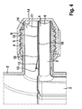
- an external thread 5 is arranged, on which a cap 6 for closing the outlet opening 4 can be turned on, as shown in FIG FIG. 4 is shown.
- the second container 3 has a smaller cross-section than the first container 2 and is rectangular, with circumferentially extending groove-like depressions 17, which facilitate a bellows-like compression of the second container 3.
- the second container 3 abuts against the first container 2 substantially over its entire length and is supported on it.
- the two containers 2, 3 serve to receive a first and a second component of a hardenable mass (not shown), which are protected by the wall of the second container 3 stored separately inside the first container 2.
- a piston 7, which closes the first container 2 as a displaceable bottom, is displaced forward in the first container 2 in the direction of the outlet section 4, whereby the first component consists of an outlet opening 18 of the outlet section 4 of the first container and the second component through an outlet opening 8 a likewise tubular outlet portion 9 of the second container 3 is pressed.
- the outlet section 9 is located in the outlet section 4 in a receiving sleeve 10, that is, it is received by the receiving sleeve 10 and held stationary.
- the receiving sleeve 10 is arranged eccentrically in the outlet section 4 on its inner wall 11 in one piece on the same side, on which the second container 3 rests against the first container 2.
- the receiving sleeve 10 forms a part of the inner wall 11 of the outlet section 4.
- the receiving sleeve 10 is formed as a cylindrical tube having at its rear end 12 a rearwardly enlarged in diameter receiving opening 13.
- the rear end 12 enlarging receiving opening 13 of the receiving sleeve 10 facilitates the insertion of the outlet portion 9 in the receiving sleeve 10th
- the receiving sleeve 10 is arranged in the outlet section 4 such that it protrudes forward, that is, in the exit direction of the components of the hardenable mass, via the outlet section 4.
- the supernatant X is 1 mm.
- the receiving sleeve 10 is also at its front end to the supernatant X in the discharge direction of the mass on the front end of the outlet section 9, whereby the outlet portion 9 is protected against injury and damage. If residues of the curable composition are present when the closure cap 6 is turned up in the region of the top surface 14, then they can bond the closure cap 6 to the front end of the receiving sleeve 10. When turning the cap 6 shear forces are transmitted to the stably running receiving sleeve 10 and not or only to a limited extent on the outlet section 9, which is protected inside the receiving sleeve 10.
- a relatively soft material can be selected and / or the second container 3 can be made thin-walled so that the second container 3 can be compressed relatively easily with the piston 7 during extrusion.
- the choice of a solid and stable material for the outlet section 9 of the container 3 is not necessary, as avoided by the eccentric arrangement of the receiving sleeve 10 a torsional stress of the outlet portion 9 and thus a twisting of the outlet portion 9 and the projection X of the receiving sleeve 10 damage the Outlet section 9 is prevented by shear forces during repeated twisting of the cap 6.
- the multicomponent cartridge 1 according to the invention is characterized by a simple construction with few parts.
- the first container 2 is dimensionally stable, but inexpensively made by injection molding of polypropylene, while the second container 3 is made as a blow-molded thin-walled from a low density polyethylene, to facilitate the bellows-like compression.
Landscapes
- Engineering & Computer Science (AREA)
- Mechanical Engineering (AREA)
- Closures For Containers (AREA)
- Package Specialized In Special Use (AREA)
Abstract
Description
- Die Erfindung betrifft eine Mehrkomponentenkartusche mit den Merkmalen des Oberbegriffs des Anspruchs 1.
- Aus der Offenlegungsschrift
DE 10 2004 056 908 A1 ist eine gattungsgemäße Mehrkomponentenkartusche bekannt. Bei der bekannten Kartusche umschließt ein erster Behälter einen zweiten Behälter. Beide Behälter sind zur Aufnahme von getrennt zu lagernden Komponenten einer aushärtbaren Masse vorgesehen. So nimmt der erste Behälter beispielsweise einen Mörtel auf, während der zweite Behälter den Härter einer Zweikomponentenmörtelmasse enthält. Zur Verarbeitung werden die beiden Komponenten durch einen Kolben aus der Kartusche ausgepresst, beispielsweise in einen auf ein Außengewinde der Kartusche aufgeschraubten Mischer zum Vermischen der Komponenten. Hierzu weist die Mehrkomponentenkartusche einen Auslassabschnitt zur Abgabe der ersten Komponente auf. Der Austritt des zweiten Behälters ist als rohrförmiger Austrittsabschnitt ausgeformt, der in einer zentrisch in dem Auslassabschnitt angeordneten Aufnahmehülse angeordnet ist. Beim Auspressen der beiden Komponenten wird der in dem ersten Behälter angeordnete Kolben in Richtung des Auslassabschnitts geschoben, wobei der zweite Behälter zusammendrückt wird. Um die zum Auspressen erforderliche Kraft möglichst gering zu halten, ist der zweite Behälter dünnwandig und wenig stabil ausgeführt. - Wird die Mehrkomponentenkartusche nicht genutzt, so wird der Auslassabschnitt durch eine Verschlusskappe verschlossen. Die Verschlusskappe wird hierzu auf das Außengewinde der Kartusche aufgeschraubt. Dabei kann es vorkommen, dass Reste der Komponenten, die in einer Auslassöffnung des Auslassabschnitts verbleiben, mit der Verschlusskappe und dem Austrittsabschnitt verkleben. Wird die Verschlusskappe wieder abgeschraubt, so wird durch die Verklebung die Drehbewegung auf den rohrförmigen und dünnwandigen Austrittsabschnitt übertragen, wodurch dieser beschädigt werden kann und aufreißt, so dass eine kontrollierte Abgabe der zweiten Komponente nicht mehr möglich ist.
- Aufgabe der Erfindung ist es daher, eine Mehrkomponentenkartusche vorzuschlagen, bei der der Austrittsabschnitt gegen Beschädigungen beim wiederholten Abdrehen der Verschlusskappe geschützt ist.
- Diese Aufgabe wird erfindungsgemäß durch eine Mehrkomponentenkartusche mit den Merkmalen des Anspruchs 1 gelöst. Bei der erfindungsgemäßen Mehrkomponentenkartusche handelt es sich insbesondere um eine Zweikomponentenkartusche. Die erfindungsgemäße Mehrkomponentenkartusche umfasst einen ersten Behälter zur Aufnahme einer ersten Komponente und einen zweiten Behälter zur Aufnahme einer zweiten Komponente einer aushärtbaren Masse. Zur Aufnahme weiterer Komponenten können weitere Behälter an der Mehrkomponentenkartusche angeordnet sein. Die Behälter können Insbesondere mit einem Kolben der Mehrkammerkartusche ausgepresst werden. Die Mehrkomponentenkartusche weist einen Auslassabschnitt mit einer Auslassöffnung zur Abgabe der ersten Komponente auf. In diesem Auslassabschnitt ist eine Aufnahmehülse angeordnet, in der ein Austrittsabschnitt des zweiten Behälters einliegt. "Einliegen" bedeutet hier insbesondere, dass der Austrittsabschnitt in der Aufnahmehülse aufgenommen ist und von ihr gehalten wird. Die Aufnahmehülse ist insbesondere unbeweglich zum und Insbesondere einstückig mit dem Auslassabschnitt. Der Austrittsabschnitt ist insbesondere zylindrisch und rohrförmig ausgestaltet und weist eine Austrittsöffnung auf, aus der die zweite Komponente aus dem zweiten Behälter austreten kann.
- Kennzeichnend für die erfindungsgemäße Mehrkomponentenkartusche ist, dass die Aufnahmehülse in Austrittsrichtung der Masse über den Auslassabschnitt übersteht, wobei der Überstand insbesondere nicht größer als 2 mm, insbesondere nicht größer als 1 mm ist. Wird die Mehrkomponentenkartusche mit einer Verschlusskappe verschlossen, so liegt das vordere Ende der Aufnahmehülse an der Verschlusskappe an, insbesondere derart, dass die Verschlusskappe das vordere Ende der Aufnahmehülse abdichtet. Hierdurch wird verhindert, dass die beiden Komponenten der aushärtbaren Masse, die sich In der Auslass- bzw. Austrittsöffnung befinden, bei aufgedrehter Verschlusskappe miteinander in Berührung kommen, miteinander reagieren und aushärten können, wenn die Mehrkomponentenkartusche mit einer Verschlusskappe verschlossen ist.
- Alternativ oder in Kombination steht die Aufnahmehülse in Austrittsrichtung der Masse über den Austrittsabschnitt über, so dass der Austrittsabschnitt geschützt innerhalb der Aufnahmehülse liegt. Der Überstand kann mehrere Millimeter betragen, ist aber insbesondere nicht größer als 2 mm, insbesondere nicht größer als 1 mm. Beim Abdrehen der Verschlusskappe führt ein unbeabsichtigtes Verkleben der Verschlusskappe mit den Behältern dazu, dass Kräfte auf die Aufnahmehülse übertragen werden, die den Austrittsabschnitt umgibt, nicht aber auf den Austrittsabschnitt selbst, der durch die Aufnahmehülse gestützt und geschützt ist. Eine Beschädigung des Austrittsabschnitts ist durch den Überstand der Aufnahmehülse ausgeschlossen. Die Aufnahmehülse kann im Vergleich zum zweiten Behälter dickwandig und stabil ausgeführt werden, so dass ein wiederholtes Öffnen der Mehrkomponentenkartusche auch zu keiner Beschädigung der Aufnahmehülse führt.
- Vorzugsweise ist die Aufnahmehülse exzentrisch in dem Auslassabschnitt angeordnet. Durch die exzentrische Anordnung wird verhindert, dass der in der Aufnahmehülse angeordnete Austrittsabschnitt beim Abdrehen der Verschlusskappe in sich verdreht wird, also tordiert, was zu großen Spannungen im Austrittsabschnitt führen würde. Durch die exzentrische Anordnung wirken im Wesentlichen Scherkräfte auf den Austrittsabschnitt, die an die Aufnahmehülse abgeleitet werden, wodurch die auf den Austrittsabschnitt wirkenden Spannungen deutlich reduziert werden. Somit ist eine Beschädigung des Austrittsabschnitts beim wiederholten Abdrehen der Verschlusskappe praktisch ausgeschlossen. Ein weiterer Vorteil der exzentrischen Anordnung ist, dass das Auspressen der ersten Komponente in deutlich geringerem Maße durch die Aufnahmehülse behindert wird, als dies bei der aus dem Stand der Technik bekannten zentrischen Anordnung der Fall ist.
- Vorzugsweise ist die Aufnahmehülse an einer Innenwand des Auslassabschnitts angeordnet. Insbesondere bildet die Aufnahmehülse einen Teil der Innenwand. Diese Ausgestaltungsform hat den Vorteil, dass die Aufnahmehülse stabil und ohne großen. Aufwand in dem Auslassabschnitt angeordnet werden kann, ohne deren Querschnitt durch Streben oder Stege unnötig zu verengen. Dadurch, dass die Aufnahmehülse einen Teil der Innenwand des Auslassabschnitts bildet, ist ein zusätzliches Ankleben oder mechanisches Verbinden der Aufnahmehülse mit der Innenwand des Auslassabschnitts nicht notwendig.
- Weiterhin ist bevorzugt, dass die Aufnahmehülse als zylindrisches Rohr ausgebildet ist, was eine Herstellung der Aufnahmehülse und eine Montage des Austrittsabschnitts in der Aufnahmehülse erleichtert.
- Vorzugsweise weist die Aufnahmehülse an ihrem hinteren Ende eine vergrößerte Aufnahmeöffnung auf, die ein Einführen des Austrittsabschnitts in die Aufnahmehülse erleichtert. Insbesondere erweitert sich die Aufnahmeöffnung konisch, insbesondere kegelförmig, nach hinten. "Hinten" bezieht sich hier auf die Austrittsrichtung, in die die Komponenten der aushärtbaren Masse aus der Auslass- bzw. Austrittsöffnung austreten.
- Eine weitere Ausgestaltungsform der erfindungsgemäßen Mehrkomponentenkartusche ist derart gestaltet, dass die Außenwand des Austrittsabschnitts vollflächig an der Innenwand der Aufnahmehülse anliegt. Insbesondere liegt die Außenwand des Austrittsabschnitts über den ganzen Umfang, dicht und insbesondere klemmend an der Innenwand der Aufnahmehülse an, so dass der Austrittsabschnitt in Umfangsrichtung gegenüber der Auslassöffnung abgedichtet ist. Die Aufnahmehülse verhindert in diesem Fall, dass die beiden Komponenten unbeabsichtigt miteinander in Kontakt kommen und reagieren können.
- Vorzugsweise ist der zweite Behälter im Inneren des ersten Behälters angeordnet, was einen einfachen Aufbau der Mehrkomponentenkartusche ermöglicht. Weiterhin ist bevorzugt, dass der zweite Behälter am ersten Behälter anliegt und auf der gleichen Seite wie die Aufnahmehülse an der Kartusche angeordnet ist. Der zweite Behälter kann sich somit beim Auspressen am ersten Behälter abstützen, behindert aber das Auspressen der ersten Komponente nicht. Mit "gleicher Seite" ist bei einem polygonalen Querschnitt gemeint, dass der Behälter an der gleichen Kante des den Querschnitt bildenden Polygons anliegt, wie die Aufnahmehülse. Bei einem kreisförmigen oder sonstigen Querschnitt bedeutet dies, dass die Aufnahmehülse und der zweite Behälter im gleichen Sektor des den Querschnitt der Kartusche umschreibenden Kreises angeordnet ist, wobei der Sektor einen Mittelpunktswinkel von circa 120°, insbesondere von weniger als 90° aufweist.
- Insbesondere ist der erste Behälter dickwandiger und stabiler als der zweite Behälter aus Kunststoff im Spritzgussverfahren hergestellt, beispielsweise aus Polypropylen (PP). Der erste Behälter ist somit formstabil und robust. Der zweite Behälter, der insbesondere vom ersten Behälter schützend umschlossen ist, ist dagegen im Vergleich zum ersten Behälter weicher und weniger formstabil, so dass er leicht verformbar und insbesondere faltenbalgartig zusammenpressbar ist. Der zweite Behälter ist beispielsweise als Blasformteil aus Kunststoff, beispielsweise aus Polyethylen geringer Dichte (LDPE) hergestellt.
- Die Erfindung wird nachfolgend anhand eines in den Figuren dargestellten Ausführungsbeispiels näher beschrieben. Es zeigen:
- Figur 1
- eine erfindungsgemäße Mehrkomponentenkartusche in einer perspektivischen Darstellung;
- Figur 2
- einen Längsschnitt durch die Mehrkomponentenkartusche der
Figur 1 ; - Figur 3
- den vorderen Bereich der Mehrkomponentenkartusche in einem Axialschnitt; und
- Figur 4
- den vorderen Bereich der Mehrkomponentenkartusche mit einer aufgeschraubten Verschlusskappe in einer perspektivischen Schnittdarstellung.
- Die in den
Figuren 1 bis 4 dargestellte Mehrkomponentenkartusche 1 weist einen äußeren, ersten Behälter 2 auf, in dessen Inneren ein zweiter Behälter 3 angeordnet ist. Der erste Behälter 2 ist als hohler Zylinder ausgeführt. Der Zylinder weist keinen festen Boden auf, aber eine Decke mit einem rohrartigen Auslassabschnitt 4, dessen Innendurchmesser gegenüber dem Durchmesser des Zylinders reduziert ist und der einen vorderen Teil des ersten Behälters 2 bildet. An der Außenseite des rohrartigen Auslassabschnitts 4 ist ein Außengewinde 5 angeordnet, auf das eine Verschlusskappe 6 zum Verschließen der Auslassöffnung 4 aufgedreht werden kann, wie dies inFigur 4 dargestellt ist. Der zweite Behälter 3 weist einen kleineren Querschnitt als der erste Behälter 2 auf und ist rechteckig ausgeführt, mit in Umfangsrichtung verlaufenden nutartigen Vertiefungen 17, die ein faltenbalgartiges Zusammendrücken des zweiten Behälters 3 erleichtern. Der zweite Behälter 3 liegt im Wesentlichen über seine gesamte Länge an dem ersten Behälter 2 an und stützt sich an ihm ab. Die beiden Behälter 2, 3 dienen zur Aufnahme einer ersten und einer zweiten Komponente einer aushärtbaren Masse (nicht dargestellt), die durch die Wand des zweiten Behälters 3 getrennt geschützt im Innern des ersten Behälters 2 lagern. Zur Abgabe der beiden Komponenten wird ein Kolben 7, der als verschiebbarer Boden den ersten Behälter 2 verschließt, im ersten Behälter 2 nach vorne, in Richtung des Auslassabschnitts 4 verschoben, wodurch die erste Komponente aus einer Auslassöffnung 18 des Auslassabschnitts 4 des ersten Behälters und die zweite Komponente durch eine Austrittsöffnung 8 eines ebenfalls rohrförmigen Austrittsabschnitts 9 des zweiten Behälters 3 gedrückt wird. Der Austrittsabschnitt 9 liegt in dem Auslassabschnitt 4 in einer Aufnahmehülse 10 ein, d.h., er ist von der Aufnahmehülse 10 aufgenommen und ortsfest gehalten. Die Aufnahmehülse 10 ist exzentrisch in dem Auslassabschnitt 4 an deren Innenwand 11 einstückig auf der gleichen Seite angeordnet, an der der zweite Behälter 3 am ersten Behälter 2 anliegt. Dabei bildet die Aufnahmehülse 10 einen Teil der Innenwand 11 des Auslassabschnitts 4. Die Aufnahmehülse 10 ist als zylindrisches Rohr ausgebildet, das an seinem hinteren Ende 12 eine sich nach hinten im Durchmesser vergrößerte Aufnahmeöffnung 13 aufweist. Die am hinteren Ende 12 vergrößernde Aufnahmeöffnung 13 der Aufnahmehülse 10 erleichtert das Einführen des Austrittsabschnitts 9 in die Aufnahmehülse 10. - Die Aufnahmehülse 10 ist in dem Auslassabschnitt 4 derart angeordnet, dass sie nach vorn, das heißt in Austrittsrichtung der Komponenten der aushärtbaren Masse, über den Auslassabschnitt 4 übersteht. Der Überstand X beträgt 1 mm. Durch den Überstand X wird erreicht, dass die Verschlusskappe 6 beim Aufdrehen auf das Außengewinde 5 mit einer inneren Deckfläche 14 am vorderen Ende der Aufnahmehülse 10 anliegt und gegen die Aufnahmehülse 10 verspannt werden kann, so dass die Aufnahmehülse 10 an ihrem vorderen Ende dicht verschlossen ist. Zudem liegt die Außenwand 15 des Austrittsabschnitts 9 über den ganzen Umfang vollflächig und klemmend an der Innenwand 16 der Aufnahmehülse 10 an. Somit ist gewährleistet, dass der Austrittsabschnitt 9 bei fest aufgedrehter Verschlusskappe 6 gegenüber dem Auslassabschnitt 4 dicht verschlossen ist und die beiden Komponenten der aushärtbaren Masse nicht miteinander in Berührung kommen und reagieren können.
- Die Aufnahmehülse 10 steht mit ihrem vorderen Ende zudem um den Überstand X in Austrittsrichtung der Masse über das vordere Ende des Austrittsabschnitts 9 über, wodurch der Austrittsabschnitt 9 gegen Verletzungen und Beschädigungen geschützt ist. Befinden sich Reste der aushärtbaren Masse bei aufgedrehter Verschlusskappe 6 im Bereich der Deckfläche 14, so können diese die Verschlusskappe 6 mit dem vorderen Ende der Aufnahmehülse 10 verkleben. Beim Abdrehen der Verschlusskappe 6 werden dadurch Scherkräfte auf die stabil ausgeführte Aufnahmehülse 10 übertragen und nicht oder nur in begrenztem Maße auf den Austrittsabschnitt 9, der geschützt im Inneren der Aufnahmehülse 10 liegt. Somit kann zur Herstellung des zweiten Behälters 3, einschließlich des Austrittsabschnitts 9, ein relativ weiches Material gewählt und/oder der zweite Behälter 3 dünnwandig ausgeführt werden, so dass sich der zweite Behälter 3 relativ leicht mit dem Kolben 7 beim Auspressen zusammendrücken lässt. Die Wahl eines festen und stabilen Materials für den Austrittsabschnitt 9 des Behälters 3 ist nicht notwendig, da durch die exzentrische Anordnung der Aufnahmehülse 10 eine Torsionsbeanspruchung des Austrittsabschnitts 9 und somit ein Abdrehen des Austrittsabschnitts 9 vermieden und durch den Überstand X der Aufnahmehülse 10 eine Beschädigung des Austrittsabschnitts 9 durch Scherkräfte beim wiederholten Abdrehen der Verschlusskappe 6 verhindert wird.
- Die erfindungsgemäße Mehrkomponentenkartusche 1 zeichnet sich durch einen einfachen Aufbau mit wenigen Teilen aus. Der erste Behälter 2 ist formstabil, aber kostengünstig im Spritzgussverfahren aus Polypropylen hergestellt, während der zweite Behälter 3 als Blasformteil dünnwandig aus einem Polyethylen geringer Dichte hergestellt ist, um das faltenbalgartige Zusammendrücken zu erleichtern.
-
- 1
- Mehrkomponentenkartusche
- 2
- erster Behälter
- 3
- zweiter Behälter
- 4
- Auslassabschnitt
- 5
- Außengewinde
- 6
- Verschlusskappe
- 7
- Kolben
- 8
- Austrittsöffnung
- 9
- Austrittsabschnitt
- 10
- Aufnahmehülse
- 11
- Innenwand des Auslassabschnitts 4
- 12
- hinteres Ende der Aufnahmehülse 10
- 13
- Aufnahmeöffnung
- 14
- Deckfläche der Verschlusskappe 6
- 15
- Außenwand des Austrittsabschnitts 9
- 16
- Innenwand der Aufnahmehülse 10
- 17
- nutartige Vertiefung
- 18
- Auslassöffnung
- X
- Überstand
Claims (9)
- Mehrkomponentenkartusche (1) mit einem ersten Behälter (2) zur Aufnahme einer ersten Komponente und einem zweiten Behälter (3) zur Aufnahme einer zweiten Komponente einer aushärtbaren Masse, wobei die Mehrkomponentenkartusche (1) einen Auslassabschnitt (4) zur Abgabe der ersten Komponente aufweist, in dem eine Aufnahmehülse (10) angeordnet ist, in der ein Austrittsabschnitt (9) des zweiten Behälters (3) einliegt,
dadurch gekennzeichnet,
dass die Aufnahmehülse (10) in Austrittsrichtung der Masse über den Auslassabschnitt (4) übersteht, und/oder
dass die Aufnahmehülse (10) in Austrittsrichtung der Masse über den Austrittsabschnitt (9) übersteht. - Mehrkomponentenkartusche nach Anspruch 1, dadurch gekennzeichnet, dass die Aufnahmehülse (10) exzentrisch in dem Auslassabschnitt (4) angeordnet ist.
- Mehrkomponentenkartusche nach Anspruch 1 oder 2, dadurch gekennzeichnet, dass die Aufnahmehülse (10) an einer Innenwand (11) des Auslassabschnitts (4) angeordnet ist.
- Mehrkomponentenkartusche nach Anspruch 3, dadurch gekennzeichnet, dass die Aufnahmehülse (10) einen Teil der Innenwand (11) bildet.
- Mehrkomponentenkartusche nach einem der Ansprüche 1 bis 4, dadurch gekennzeichnet, dass die Aufnahmehülse (10) als zylindrisches Rohr ausgebildet ist.
- Mehrkomponentenkartusche nach einem der Ansprüche 1 bis 5, dadurch gekennzeichnet, dass die Aufnahmehülse (10) an ihrem hinteren Ende (12) eine vergrößerte Aufnahmeöffnung (13) aufweist.
- Mehrkomponentenkartusche nach einem der Ansprüche 1 bis 6, dadurch gekennzeichnet, dass die Außenwand (15) des Austrittsabschnitts (9) vollflächig an der Innenwand (16) der Aufnahmehülse (10) anliegt.
- Mehrkomponentenkartusche nach einem der Ansprüche 1 bis 7, dadurch gekennzeichnet, dass der zweite Behälter (3) im Inneren des ersten Behälters (2) angeordnet ist.
- Mehrkomponentenkartusche nach einem der Ansprüche 1 bis 8, dadurch gekennzeichnet, dass der zweite Behälter (3) am ersten Behälter (2) anliegt und auf der gleichen Seite wie die Aufnahmehülse (10) an der Mehrkomponentenkartusche (1) angeordnet ist.
Applications Claiming Priority (2)
| Application Number | Priority Date | Filing Date | Title |
|---|---|---|---|
| DE102013111404 | 2013-10-16 | ||
| DE201410013679 DE102014013679A1 (de) | 2013-10-16 | 2014-09-17 | Mehrkomponentenkartusche |
Publications (2)
| Publication Number | Publication Date |
|---|---|
| EP2862812A1 true EP2862812A1 (de) | 2015-04-22 |
| EP2862812B1 EP2862812B1 (de) | 2016-07-13 |
Family
ID=51690191
Family Applications (1)
| Application Number | Title | Priority Date | Filing Date |
|---|---|---|---|
| EP14003467.9A Not-in-force EP2862812B1 (de) | 2013-10-16 | 2014-10-09 | Mehrkomponentenkartusche |
Country Status (3)
| Country | Link |
|---|---|
| EP (1) | EP2862812B1 (de) |
| CN (1) | CN104554959B (de) |
| DE (1) | DE102014013679A1 (de) |
Cited By (2)
| Publication number | Priority date | Publication date | Assignee | Title |
|---|---|---|---|---|
| US10166057B2 (en) | 2016-04-28 | 2019-01-01 | Heraeus Medical Gmbh | Storage and mixing system with compressible internal cartridge for pasty starting components |
| US11596972B2 (en) | 2019-01-03 | 2023-03-07 | Medmix Switzerland Ag | Coaxial cartridge for multi-component materials and method of assembling a coaxial cartridge |
Citations (6)
| Publication number | Priority date | Publication date | Assignee | Title |
|---|---|---|---|---|
| US3266671A (en) * | 1963-12-16 | 1966-08-16 | Gelpey Kenneth | Compartmented dispenser for plural fluids |
| EP0093185A1 (de) * | 1982-05-03 | 1983-11-09 | Voplex Corporation | Dosierspender für zwei Viskose-Komponenten |
| DE102004056908A1 (de) | 2004-11-25 | 2006-06-01 | Fischerwerke Artur Fischer Gmbh & Co. Kg | Mehrkomponenten-Kartusche |
| DE102007051968A1 (de) * | 2007-10-31 | 2009-05-07 | Fischerwerke Gmbh & Co. Kg | Mehrkomponenten-Kartusche |
| EP2199228A1 (de) * | 2008-12-19 | 2010-06-23 | fischerwerke GmbH & Co. KG | Mehrkomponentenkartusche. |
| FR2976927A3 (fr) * | 2011-06-21 | 2012-12-28 | Fastfix It Entpr Co Ltd | Cartouche contenant un liant principal et un agent de durcissement |
Family Cites Families (5)
| Publication number | Priority date | Publication date | Assignee | Title |
|---|---|---|---|---|
| DE102005017599A1 (de) * | 2005-04-16 | 2006-10-19 | Fischerwerke Artur Fischer Gmbh & Co. Kg | Mehrkomponenten-Kartusche |
| FR2886274B1 (fr) * | 2005-05-30 | 2010-02-26 | Cebal Sas | Amelioration de l'etancheite des emballages a recipients multiples, en particulier des doubles tubes, destines notamment aux preparations extemporanees |
| CN200964220Y (zh) * | 2006-10-26 | 2007-10-24 | 厦门鹏拓塑胶制品有限公司 | 塑胶软管结构 |
| DE102009016943A1 (de) * | 2009-04-08 | 2010-10-14 | Fischerwerke Gmbh & Co. Kg | Mehrkomponenten-Kartusche |
| EP2384883A1 (de) * | 2010-05-06 | 2011-11-09 | Sulzer Mixpac AG | Verfahren zur Herstellung einer Kartusche sowie eine solche Kartusche |
-
2014
- 2014-09-17 DE DE201410013679 patent/DE102014013679A1/de not_active Withdrawn
- 2014-10-09 EP EP14003467.9A patent/EP2862812B1/de not_active Not-in-force
- 2014-10-16 CN CN201410547236.7A patent/CN104554959B/zh not_active Expired - Fee Related
Patent Citations (6)
| Publication number | Priority date | Publication date | Assignee | Title |
|---|---|---|---|---|
| US3266671A (en) * | 1963-12-16 | 1966-08-16 | Gelpey Kenneth | Compartmented dispenser for plural fluids |
| EP0093185A1 (de) * | 1982-05-03 | 1983-11-09 | Voplex Corporation | Dosierspender für zwei Viskose-Komponenten |
| DE102004056908A1 (de) | 2004-11-25 | 2006-06-01 | Fischerwerke Artur Fischer Gmbh & Co. Kg | Mehrkomponenten-Kartusche |
| DE102007051968A1 (de) * | 2007-10-31 | 2009-05-07 | Fischerwerke Gmbh & Co. Kg | Mehrkomponenten-Kartusche |
| EP2199228A1 (de) * | 2008-12-19 | 2010-06-23 | fischerwerke GmbH & Co. KG | Mehrkomponentenkartusche. |
| FR2976927A3 (fr) * | 2011-06-21 | 2012-12-28 | Fastfix It Entpr Co Ltd | Cartouche contenant un liant principal et un agent de durcissement |
Cited By (2)
| Publication number | Priority date | Publication date | Assignee | Title |
|---|---|---|---|---|
| US10166057B2 (en) | 2016-04-28 | 2019-01-01 | Heraeus Medical Gmbh | Storage and mixing system with compressible internal cartridge for pasty starting components |
| US11596972B2 (en) | 2019-01-03 | 2023-03-07 | Medmix Switzerland Ag | Coaxial cartridge for multi-component materials and method of assembling a coaxial cartridge |
Also Published As
| Publication number | Publication date |
|---|---|
| DE102014013679A1 (de) | 2015-04-16 |
| CN104554959B (zh) | 2018-02-16 |
| EP2862812B1 (de) | 2016-07-13 |
| CN104554959A (zh) | 2015-04-29 |
Similar Documents
| Publication | Publication Date | Title |
|---|---|---|
| EP1925370B1 (de) | Mehrkomponentenkartusche | |
| EP2444336B1 (de) | Doppel-Austragsvorrichtung | |
| DE602004003563T2 (de) | Abgabevorrichtung | |
| DE202005001203U1 (de) | Mehrkomponentenfolienbehälter | |
| EP3405293B1 (de) | Foliengebinde sowie baugruppe aus einer auspressvorrichtung und einem foliengebinde | |
| EP2630931A1 (de) | Abgabebehälter für Dentalmasse | |
| EP2862812B1 (de) | Mehrkomponentenkartusche | |
| EP1212984B1 (de) | Spritze zum dosierten Abgeben von dentalen Werkstoffen | |
| DE102016122041A1 (de) | Mehrkomponentenbehältnis | |
| DE102016107911A1 (de) | Lagerungs- und Mischsystem für pastenförmige Ausgangskomponenten mit auspressbarer Innenkartusche | |
| DE10207763A1 (de) | Mehrkomponenten-Kartusche | |
| EP2862813A1 (de) | Mehrkomponentenkartusche | |
| DE10218859A1 (de) | Kapsel aus Kunststoff zur Aufbewahrung und Abgabe von Dentalmaterial | |
| DE20120142U1 (de) | Sprühdose | |
| DE19911728C2 (de) | Verfahren zur Herstellung einer Zweikammertube | |
| EP1761342A1 (de) | Ausgabeaufsatz | |
| DE102007051968A1 (de) | Mehrkomponenten-Kartusche | |
| EP2199228B1 (de) | Mehrkomponentenkartusche | |
| DE102009017980A1 (de) | Kunststoffkapsel zum Lagern und Ausbringen von fließfähigen Dentalwerkstoffen sowie Applikator zu deren Aufnahme | |
| DE102007005052A1 (de) | Adapterkappe für einen Druckbehälter | |
| DE102018117146A1 (de) | Mehrkammerkartusche | |
| EP1986929B1 (de) | Mehrkomponenten-kartusche | |
| EP2707304B1 (de) | Zweiteiliger, kindersicherer verschluss | |
| DE4012073C2 (de) | Behälter für flüssige oder pastöse Massen | |
| EP1961673A1 (de) | Zweikomponentenkartusche |
Legal Events
| Date | Code | Title | Description |
|---|---|---|---|
| PUAI | Public reference made under article 153(3) epc to a published international application that has entered the european phase |
Free format text: ORIGINAL CODE: 0009012 |
|
| 17P | Request for examination filed |
Effective date: 20141009 |
|
| AK | Designated contracting states |
Kind code of ref document: A1 Designated state(s): AL AT BE BG CH CY CZ DE DK EE ES FI FR GB GR HR HU IE IS IT LI LT LU LV MC MK MT NL NO PL PT RO RS SE SI SK SM TR |
|
| AX | Request for extension of the european patent |
Extension state: BA ME |
|
| R17P | Request for examination filed (corrected) |
Effective date: 20151016 |
|
| RBV | Designated contracting states (corrected) |
Designated state(s): AL AT BE BG CH CY CZ DE DK EE ES FI FR GB GR HR HU IE IS IT LI LT LU LV MC MK MT NL NO PL PT RO RS SE SI SK SM TR |
|
| GRAP | Despatch of communication of intention to grant a patent |
Free format text: ORIGINAL CODE: EPIDOSNIGR1 |
|
| RIC1 | Information provided on ipc code assigned before grant |
Ipc: B65D 81/32 20060101AFI20160216BHEP |
|
| INTG | Intention to grant announced |
Effective date: 20160308 |
|
| GRAS | Grant fee paid |
Free format text: ORIGINAL CODE: EPIDOSNIGR3 |
|
| GRAA | (expected) grant |
Free format text: ORIGINAL CODE: 0009210 |
|
| AK | Designated contracting states |
Kind code of ref document: B1 Designated state(s): AL AT BE BG CH CY CZ DE DK EE ES FI FR GB GR HR HU IE IS IT LI LT LU LV MC MK MT NL NO PL PT RO RS SE SI SK SM TR |
|
| REG | Reference to a national code |
Ref country code: GB Ref legal event code: FG4D Free format text: NOT ENGLISH |
|
| REG | Reference to a national code |
Ref country code: AT Ref legal event code: REF Ref document number: 812097 Country of ref document: AT Kind code of ref document: T Effective date: 20160715 Ref country code: CH Ref legal event code: EP |
|
| REG | Reference to a national code |
Ref country code: IE Ref legal event code: FG4D Free format text: LANGUAGE OF EP DOCUMENT: GERMAN |
|
| REG | Reference to a national code |
Ref country code: DE Ref legal event code: R096 Ref document number: 502014001066 Country of ref document: DE |
|
| REG | Reference to a national code |
Ref country code: NL Ref legal event code: FP |
|
| REG | Reference to a national code |
Ref country code: FR Ref legal event code: PLFP Year of fee payment: 3 |
|
| REG | Reference to a national code |
Ref country code: LT Ref legal event code: MG4D |
|
| PG25 | Lapsed in a contracting state [announced via postgrant information from national office to epo] |
Ref country code: LT Free format text: LAPSE BECAUSE OF FAILURE TO SUBMIT A TRANSLATION OF THE DESCRIPTION OR TO PAY THE FEE WITHIN THE PRESCRIBED TIME-LIMIT Effective date: 20160713 Ref country code: HR Free format text: LAPSE BECAUSE OF FAILURE TO SUBMIT A TRANSLATION OF THE DESCRIPTION OR TO PAY THE FEE WITHIN THE PRESCRIBED TIME-LIMIT Effective date: 20160713 Ref country code: RS Free format text: LAPSE BECAUSE OF FAILURE TO SUBMIT A TRANSLATION OF THE DESCRIPTION OR TO PAY THE FEE WITHIN THE PRESCRIBED TIME-LIMIT Effective date: 20160713 Ref country code: IS Free format text: LAPSE BECAUSE OF FAILURE TO SUBMIT A TRANSLATION OF THE DESCRIPTION OR TO PAY THE FEE WITHIN THE PRESCRIBED TIME-LIMIT Effective date: 20161113 Ref country code: FI Free format text: LAPSE BECAUSE OF FAILURE TO SUBMIT A TRANSLATION OF THE DESCRIPTION OR TO PAY THE FEE WITHIN THE PRESCRIBED TIME-LIMIT Effective date: 20160713 Ref country code: NO Free format text: LAPSE BECAUSE OF FAILURE TO SUBMIT A TRANSLATION OF THE DESCRIPTION OR TO PAY THE FEE WITHIN THE PRESCRIBED TIME-LIMIT Effective date: 20161013 |
|
| PG25 | Lapsed in a contracting state [announced via postgrant information from national office to epo] |
Ref country code: SE Free format text: LAPSE BECAUSE OF FAILURE TO SUBMIT A TRANSLATION OF THE DESCRIPTION OR TO PAY THE FEE WITHIN THE PRESCRIBED TIME-LIMIT Effective date: 20160713 Ref country code: PT Free format text: LAPSE BECAUSE OF FAILURE TO SUBMIT A TRANSLATION OF THE DESCRIPTION OR TO PAY THE FEE WITHIN THE PRESCRIBED TIME-LIMIT Effective date: 20161114 Ref country code: ES Free format text: LAPSE BECAUSE OF FAILURE TO SUBMIT A TRANSLATION OF THE DESCRIPTION OR TO PAY THE FEE WITHIN THE PRESCRIBED TIME-LIMIT Effective date: 20160713 Ref country code: LV Free format text: LAPSE BECAUSE OF FAILURE TO SUBMIT A TRANSLATION OF THE DESCRIPTION OR TO PAY THE FEE WITHIN THE PRESCRIBED TIME-LIMIT Effective date: 20160713 Ref country code: PL Free format text: LAPSE BECAUSE OF FAILURE TO SUBMIT A TRANSLATION OF THE DESCRIPTION OR TO PAY THE FEE WITHIN THE PRESCRIBED TIME-LIMIT Effective date: 20160713 Ref country code: BE Free format text: LAPSE BECAUSE OF NON-PAYMENT OF DUE FEES Effective date: 20161031 Ref country code: GR Free format text: LAPSE BECAUSE OF FAILURE TO SUBMIT A TRANSLATION OF THE DESCRIPTION OR TO PAY THE FEE WITHIN THE PRESCRIBED TIME-LIMIT Effective date: 20161014 |
|
| REG | Reference to a national code |
Ref country code: DE Ref legal event code: R097 Ref document number: 502014001066 Country of ref document: DE |
|
| PG25 | Lapsed in a contracting state [announced via postgrant information from national office to epo] |
Ref country code: EE Free format text: LAPSE BECAUSE OF FAILURE TO SUBMIT A TRANSLATION OF THE DESCRIPTION OR TO PAY THE FEE WITHIN THE PRESCRIBED TIME-LIMIT Effective date: 20160713 Ref country code: RO Free format text: LAPSE BECAUSE OF FAILURE TO SUBMIT A TRANSLATION OF THE DESCRIPTION OR TO PAY THE FEE WITHIN THE PRESCRIBED TIME-LIMIT Effective date: 20160713 |
|
| PLBE | No opposition filed within time limit |
Free format text: ORIGINAL CODE: 0009261 |
|
| STAA | Information on the status of an ep patent application or granted ep patent |
Free format text: STATUS: NO OPPOSITION FILED WITHIN TIME LIMIT |
|
| PG25 | Lapsed in a contracting state [announced via postgrant information from national office to epo] |
Ref country code: SK Free format text: LAPSE BECAUSE OF FAILURE TO SUBMIT A TRANSLATION OF THE DESCRIPTION OR TO PAY THE FEE WITHIN THE PRESCRIBED TIME-LIMIT Effective date: 20160713 Ref country code: BG Free format text: LAPSE BECAUSE OF FAILURE TO SUBMIT A TRANSLATION OF THE DESCRIPTION OR TO PAY THE FEE WITHIN THE PRESCRIBED TIME-LIMIT Effective date: 20161013 Ref country code: SM Free format text: LAPSE BECAUSE OF FAILURE TO SUBMIT A TRANSLATION OF THE DESCRIPTION OR TO PAY THE FEE WITHIN THE PRESCRIBED TIME-LIMIT Effective date: 20160713 Ref country code: CZ Free format text: LAPSE BECAUSE OF FAILURE TO SUBMIT A TRANSLATION OF THE DESCRIPTION OR TO PAY THE FEE WITHIN THE PRESCRIBED TIME-LIMIT Effective date: 20160713 Ref country code: DK Free format text: LAPSE BECAUSE OF FAILURE TO SUBMIT A TRANSLATION OF THE DESCRIPTION OR TO PAY THE FEE WITHIN THE PRESCRIBED TIME-LIMIT Effective date: 20160713 |
|
| 26N | No opposition filed |
Effective date: 20170418 |
|
| REG | Reference to a national code |
Ref country code: IE Ref legal event code: MM4A |
|
| PG25 | Lapsed in a contracting state [announced via postgrant information from national office to epo] |
Ref country code: LU Free format text: LAPSE BECAUSE OF NON-PAYMENT OF DUE FEES Effective date: 20161009 Ref country code: SI Free format text: LAPSE BECAUSE OF FAILURE TO SUBMIT A TRANSLATION OF THE DESCRIPTION OR TO PAY THE FEE WITHIN THE PRESCRIBED TIME-LIMIT Effective date: 20160713 |
|
| REG | Reference to a national code |
Ref country code: FR Ref legal event code: PLFP Year of fee payment: 4 |
|
| PG25 | Lapsed in a contracting state [announced via postgrant information from national office to epo] |
Ref country code: IE Free format text: LAPSE BECAUSE OF NON-PAYMENT OF DUE FEES Effective date: 20161009 |
|
| REG | Reference to a national code |
Ref country code: BE Ref legal event code: MM Effective date: 20161031 |
|
| PGFP | Annual fee paid to national office [announced via postgrant information from national office to epo] |
Ref country code: CH Payment date: 20171019 Year of fee payment: 4 Ref country code: NL Payment date: 20171019 Year of fee payment: 4 |
|
| PG25 | Lapsed in a contracting state [announced via postgrant information from national office to epo] |
Ref country code: HU Free format text: LAPSE BECAUSE OF FAILURE TO SUBMIT A TRANSLATION OF THE DESCRIPTION OR TO PAY THE FEE WITHIN THE PRESCRIBED TIME-LIMIT; INVALID AB INITIO Effective date: 20141009 |
|
| PG25 | Lapsed in a contracting state [announced via postgrant information from national office to epo] |
Ref country code: MT Free format text: LAPSE BECAUSE OF FAILURE TO SUBMIT A TRANSLATION OF THE DESCRIPTION OR TO PAY THE FEE WITHIN THE PRESCRIBED TIME-LIMIT Effective date: 20160713 Ref country code: MC Free format text: LAPSE BECAUSE OF FAILURE TO SUBMIT A TRANSLATION OF THE DESCRIPTION OR TO PAY THE FEE WITHIN THE PRESCRIBED TIME-LIMIT Effective date: 20160713 Ref country code: CY Free format text: LAPSE BECAUSE OF FAILURE TO SUBMIT A TRANSLATION OF THE DESCRIPTION OR TO PAY THE FEE WITHIN THE PRESCRIBED TIME-LIMIT Effective date: 20160713 Ref country code: MK Free format text: LAPSE BECAUSE OF FAILURE TO SUBMIT A TRANSLATION OF THE DESCRIPTION OR TO PAY THE FEE WITHIN THE PRESCRIBED TIME-LIMIT Effective date: 20160713 |
|
| REG | Reference to a national code |
Ref country code: FR Ref legal event code: PLFP Year of fee payment: 5 |
|
| PG25 | Lapsed in a contracting state [announced via postgrant information from national office to epo] |
Ref country code: TR Free format text: LAPSE BECAUSE OF FAILURE TO SUBMIT A TRANSLATION OF THE DESCRIPTION OR TO PAY THE FEE WITHIN THE PRESCRIBED TIME-LIMIT Effective date: 20160713 Ref country code: AL Free format text: LAPSE BECAUSE OF FAILURE TO SUBMIT A TRANSLATION OF THE DESCRIPTION OR TO PAY THE FEE WITHIN THE PRESCRIBED TIME-LIMIT Effective date: 20160713 |
|
| REG | Reference to a national code |
Ref country code: CH Ref legal event code: PL |
|
| REG | Reference to a national code |
Ref country code: NL Ref legal event code: MM Effective date: 20181101 |
|
| GBPC | Gb: european patent ceased through non-payment of renewal fee |
Effective date: 20181009 |
|
| PG25 | Lapsed in a contracting state [announced via postgrant information from national office to epo] |
Ref country code: NL Free format text: LAPSE BECAUSE OF NON-PAYMENT OF DUE FEES Effective date: 20181101 |
|
| PG25 | Lapsed in a contracting state [announced via postgrant information from national office to epo] |
Ref country code: CH Free format text: LAPSE BECAUSE OF NON-PAYMENT OF DUE FEES Effective date: 20181031 Ref country code: LI Free format text: LAPSE BECAUSE OF NON-PAYMENT OF DUE FEES Effective date: 20181031 |
|
| PG25 | Lapsed in a contracting state [announced via postgrant information from national office to epo] |
Ref country code: GB Free format text: LAPSE BECAUSE OF NON-PAYMENT OF DUE FEES Effective date: 20181009 |
|
| PGFP | Annual fee paid to national office [announced via postgrant information from national office to epo] |
Ref country code: DE Payment date: 20190830 Year of fee payment: 6 |
|
| PGFP | Annual fee paid to national office [announced via postgrant information from national office to epo] |
Ref country code: IT Payment date: 20191028 Year of fee payment: 6 Ref country code: FR Payment date: 20191028 Year of fee payment: 6 |
|
| REG | Reference to a national code |
Ref country code: AT Ref legal event code: MM01 Ref document number: 812097 Country of ref document: AT Kind code of ref document: T Effective date: 20191009 |
|
| PG25 | Lapsed in a contracting state [announced via postgrant information from national office to epo] |
Ref country code: AT Free format text: LAPSE BECAUSE OF NON-PAYMENT OF DUE FEES Effective date: 20191009 |
|
| REG | Reference to a national code |
Ref country code: DE Ref legal event code: R119 Ref document number: 502014001066 Country of ref document: DE |
|
| PG25 | Lapsed in a contracting state [announced via postgrant information from national office to epo] |
Ref country code: DE Free format text: LAPSE BECAUSE OF NON-PAYMENT OF DUE FEES Effective date: 20210501 Ref country code: FR Free format text: LAPSE BECAUSE OF NON-PAYMENT OF DUE FEES Effective date: 20201031 |
|
| PG25 | Lapsed in a contracting state [announced via postgrant information from national office to epo] |
Ref country code: IT Free format text: LAPSE BECAUSE OF NON-PAYMENT OF DUE FEES Effective date: 20201009 |