EP2862774A1 - Rail car and door bag column - Google Patents
Rail car and door bag column Download PDFInfo
- Publication number
- EP2862774A1 EP2862774A1 EP20130804416 EP13804416A EP2862774A1 EP 2862774 A1 EP2862774 A1 EP 2862774A1 EP 20130804416 EP20130804416 EP 20130804416 EP 13804416 A EP13804416 A EP 13804416A EP 2862774 A1 EP2862774 A1 EP 2862774A1
- Authority
- EP
- European Patent Office
- Prior art keywords
- side entrance
- sliding door
- door pocket
- door
- entrance
- Prior art date
- Legal status (The legal status is an assumption and is not a legal conclusion. Google has not performed a legal analysis and makes no representation as to the accuracy of the status listed.)
- Granted
Links
Images


Classifications
-
- B—PERFORMING OPERATIONS; TRANSPORTING
- B61—RAILWAYS
- B61D—BODY DETAILS OR KINDS OF RAILWAY VEHICLES
- B61D17/00—Construction details of vehicle bodies
-
- B—PERFORMING OPERATIONS; TRANSPORTING
- B61—RAILWAYS
- B61D—BODY DETAILS OR KINDS OF RAILWAY VEHICLES
- B61D19/00—Door arrangements specially adapted for rail vehicles
-
- B—PERFORMING OPERATIONS; TRANSPORTING
- B61—RAILWAYS
- B61D—BODY DETAILS OR KINDS OF RAILWAY VEHICLES
- B61D17/00—Construction details of vehicle bodies
- B61D17/04—Construction details of vehicle bodies with bodies of metal; with composite, e.g. metal and wood body structures
- B61D17/08—Sides
-
- B—PERFORMING OPERATIONS; TRANSPORTING
- B61—RAILWAYS
- B61D—BODY DETAILS OR KINDS OF RAILWAY VEHICLES
- B61D19/00—Door arrangements specially adapted for rail vehicles
- B61D19/02—Door arrangements specially adapted for rail vehicles for carriages
Definitions
- the present invention relates to a railcar and particularly to structures around a side entrance.
- a side sliding door that opens or closes a side entrance adopts an airtight structure to suppress pressure variation inside the railcar.
- a railcar 100 configured such that both end portions of a side sliding door 120 are respectively pressed, via rubber seals 150, against a door pocket post 130 and a door stop post 140 respectively provided at both sides of a side entrance 110.
- the door pocket post 130 has to have relatively high stiffness.
- the door pocket post 130 has a double skin structure that is flat in a car-longitudinal direction.
- the door pocket post 130 is configured such that an outer portion 131 and an inner portion 132 are coupled to each other by coupling portions 133.
- an edge portion 135, extending along the side entrance 110, of the door pocket post 130 is located outwardly of the inner portion 132 in a car-width direction, and a rubber seal 150 is attached to the edge portion 135.
- the inner portion 132 gets close to the side sliding door 120 when the side sliding door 120 is pulled into a door pocket space adjacent to the inner portion 132.
- a certain clearance needs to be secured between the side sliding door 120 and a bodyshell (the door pocket post 130) over the entire surface of the inner portion 132. Therefore, in a case where the clearance between the side sliding door 120 and the door pocket post 130 is narrow, the clearance needs to be increased.
- the side sliding door 120 and the bodyshell including the door pocket post 130 are separately manufactured. Therefore, the above operation of adjusting the clearance is performed in a step of incorporating the side sliding door 120 in the bodyshell after the bodyshell is manufactured. For example, the operation of adjusting the clearance for satisfactorily pulling the side sliding door into the door pocket space is performed in such a manner that the clearance between the door pocket post 130 and the side sliding door 120 is increased to become equal to or larger than a certain value over the entire surface of the inner portion 132 by, for example, heating an area, including the door pocket post 130, of the bodyshell while pressing the door pocket post 130 by a hydraulic jack or the like.
- the side sliding door 120 and the bodyshell require both the operation of adjusting the clearance for satisfactorily pulling the side sliding door 120 into the door pocket space and the operation of adjusting the clearance for securing the airtightness at the time of the door closed state.
- a problem of the conventional railcar is that it requires a lot of labor and time to adjust the clearance between the side sliding door and the bodyshell as above.
- an object of the present invention is to provide a railcar capable of reducing an operation of adjusting a clearance between a side sliding door and a bodyshell, and a door pocket post suitable for this railcar.
- a railcar of the present invention includes: a side entrance peripheral member including a door pocket post and surrounding a side entrance, the door pocket post having a double skin structure in which an outer portion and an inner portion are coupled to each other by a coupling portion , the inner portion being provided inwardly of the outer portion in a car-width direction; and a side sliding door including a peripheral portion that is pressed against an edge portion, extending along the side entrance, of the side entrance peripheral member via a rubber seal at the time of a closed state of the side entrance, the side sliding door being pulled into a door pocket space, adjacent to the inner portion of the door pocket post, at the time of an open state of the side entrance, wherein a projecting portion projecting inwardly in the car-width direction beyond the inner portion and including a tip end that contacts the rubber seal is provided at at least a part of a region constituted by an upper edge and lower edge of the edge portion of the side entrance peripheral member and a lateral edge, located at the door pocket post side,
- the projecting portion that contacts the rubber seal is provided at the edge portion of the side entrance peripheral member. Therefore, the clearance (clearance for satisfactorily pulling the side sliding door into the door pocket space) between the inner portion of the door pocket post and the side sliding door becomes larger than the clearance (clearance for securing the airtightness) between the projecting portion and the side sliding door.
- the operation of adjusting the clearance is required only at a narrow range corresponding to the projecting portion. Thus, the operation of adjusting the clearance between the side sliding door and the bodyshell can be reduced.
- a door pocket post of the present invention is a door pocket post provided at one side of a side entrance of a railcar and includes: an outer portion; an inner portion provided inwardly of the outer portion in a car-width direction; a coupling portion coupling the outer portion and the inner portion; a vertical bar portion where an end portion, located at the side entrance side, of the outer portion and an end portion, located at the side entrance side, of the inner portion converge; and a projecting portion provided at the vertical bar portion and projecting inwardly in the car-width direction beyond the inner portion.
- the present invention can provide a railcar capable of reducing an operation of adjusting a clearance between a side sliding door and a bodyshell, and a door pocket post suitable for this railcar.
- Fig. 1 shows a railcar 1 according to one embodiment of the present invention.
- the railcar 1 includes: a side entrance peripheral member 7 surrounding a side entrance 2; and a side sliding door 3 configured to open and close the side entrance 2.
- a left-right direction corresponds to a car-longitudinal direction
- an upper-lower direction corresponds to a car-width direction.
- the side entrance 2 has a vertically long, substantially rectangular shape.
- the side entrance peripheral member 7 includes a frame-shaped edge portion extending along the side entrance 2.
- the side entrance peripheral member 7 includes: a door stop post 5 and a door pocket post 6 respectively provided at left and right sides of the side entrance 2; a lintel member 16 provided at an upper side of the side entrance 2; and a doorsill member 17 provided at a lower side of the side entrance 2.
- the side entrance peripheral member 7 includes: fixed side corner members 13 respectively provided between the door stop post 5 and the lintel member 16 and between the door stop post 5 and the doorsill member 17; and movable side corner members 14 respectively provided between the door pocket post 6 and the lintel member 16 and between the door pocket post 6 and the doorsill member 17.
- the corner members 13 and 14 respectively form four quarter-circular corners of the side entrance 2.
- the configuration of the side entrance peripheral member 7 is not limited to the configuration shown in Fig. 2A .
- the door pocket post 6 may be joined to a side sill constituting an underframe.
- the door pocket post 6 may be joined to the lintel member 16 or a cantrail 18.
- each of the door pocket post 6 and the door stop post 5 extends in the upper-lower direction while slightly curving along the contours of the railcar 1 in the car-width direction.
- the door pocket post 6 and the door stop post 5 are members formed by extrusion and are provided such that an extrusion direction corresponds to its longitudinal direction.
- a plurality of shape members 15 each extending in the car-longitudinal direction are lined up in the upper-lower direction so as to be located at a side of the door pocket post 6, the side being opposite to a side where the side entrance 2 is provided.
- the shape members 15 and the door pocket post 6 are joined to one another by welding.
- the door pocket post 6 and the shape members 15 covers, from an outer side in the car-width direction, a door pocket space 10 (see Fig. 1 ) into which the side sliding door 3 is pulled.
- a pair of covers 11 that form a passage extending from a car-inner space to the side entrance 2 are provided inwardly of the side sliding door 3 in the car-width direction.
- Each of the covers 11 has a substantially U-shaped cross section, and the U shapes of the covers 11 are open in directions opposite to each other.
- the cover 11 located at the door pocket post 6 side separates the door pocket space 10 from the car-inner space and the passage, and a stopper 30 is provided between the cover 11 located at the door stop post 5 side and the door stop post 5 such that the side sliding door 3 contacts the stopper 30 to stop.
- the door pocket post 6 and the door stop post 5 respectively include vertical bar portions 64 and 51 extending along the side entrance 2. Each of outer surfaces of the vertical bar portions 64 and 51 inclines inwardly in the car-width direction as it gets close to the side entrance 2. Each of the vertical bar portions 64 and 51 tapers toward the side entrance 2.
- the vertical bar portion 64 of the door pocket post 6 and portions of the movable side corner members 14 constitute one of lateral edges of the edge portion of the side entrance peripheral member 7, each of the portions being located at the door pocket post 6 side of an intermediate point of a circular-arc portion of the movable side corner member 14.
- the vertical bar portion 51 of the door stop post 5 and portions of the fixed side corner members 13 constitute the other lateral edge of the edge portion of the side entrance peripheral member 7, each of the portions being located at the door stop post 5 side of the intermediate point of the circular-arc portion of the fixed side corner member 13.
- a lower portion of the lintel member 16, a portion of the corner member 13 located at the upper side, and a portion of the corner member 14 located at the upper side constitute an upper edge of the edge portion of the side entrance peripheral member 7, the portion of the corner member 13 being located at the lintel member 16 side of the intermediate point of the circular-arc portion of the corner member 13, the portion of the corner member 14 being located at the lintel member 16 side of the intermediate point of the circular-arc portion of the corner member 14.
- An upper portion of the doorsill member 17, a portion of the corner member 13 located at the lower side, and a portion of the corner member 14 located at the lower side constitute a lower edge of the edge portion of the side entrance peripheral member 7, the portion of the corner member 13 being located at the doorsill member 17 side of the intermediate point of the circular-arc portion of the corner member 13, the portion of the corner member 14 being located at the doorsill member 17 side of the intermediate point of the circular-arc portion of the corner member 14.
- the side sliding door 3 has a vertically long, rectangular shape slightly larger than the side entrance 2.
- the side sliding door 3 is moved by a driving unit, not shown, along the car-longitudinal direction between a closed position where both width direction end portions of the side sliding door 3 respectively overlap the vertical bar portion 64 of the door pocket post 6 and the edge portion 51 of the door stop post 5 and an open position where the side sliding door 3 is opposed to the door pocket post 6 and the shape members 15.
- a contact member 35 configured to contact the stopper 30 when the side sliding door 3 is moved to the closed position is attached to an end surface of the side sliding door 3, the end surface being located at the door stop post 5 side.
- an annular rubber seal 4 along a peripheral portion of the side sliding door 3 is attached to the peripheral portion.
- a step portion 31 is formed at the peripheral portion of the side sliding door 3.
- the step portion 31 is depressed inwardly in the car-width direction from a main surface 3a, facing outwardly in the car-width direction, of the side sliding door 3.
- the rubber seal 4 is fixed to the step portion 31.
- Cylinders 12 are respectively provided in spaces respectively surrounded by the covers 11. At the time of the closed state of the side entrance 2, the cylinders 12 are used for the purpose of pressing the peripheral portion of the side sliding door 3 via the rubber seal 4 against the edge portion, extending along the side entrance 2, of the side entrance peripheral member 7.
- the cylinders 12 may be provided such that rods thereof extend and contract in the car-width direction to allow the cylinders 12 to directly push both width direction end portions of the side sliding door 3 or such that the rods thereof extend and contract in the upper-lower direction to allow the cylinders 12 to push both end portions of the side sliding door 3 via link mechanisms.
- the peripheral portion of the side sliding door 3 does not necessarily have to be pressed against the edge portion of the side entrance peripheral member 7 via the rubber seal 4 over the entire periphery.
- the rubber seal 4 may have an inverted U shape that is open downward, and the peripheral portion of the side sliding door 3 may be pressed against the lateral edges and upper edge of the edge portion of the side entrance 7.
- the door pocket post 6 has a double skin structure that is flat in the car-longitudinal direction.
- the door pocket post 6 includes: an outer portion 61 facing outwardly in the width direction; and an inner portion 62 provided inwardly of the outer portion 61 in the car-width direction.
- the outer portion 61 and the inner portion 62 are coupled to each other by a plurality of coupling portions 63. In other words, voids are secured between the outer portion 61 and the inner portion 62 by the coupling portions 63.
- the inner portion 62 is linearly connected to the vertical bar portion 64.
- an end portion, located at the side entrance 2 side, of the outer portion 61 is bent inwardly in the car-width direction so as to form an inclined surface that is continuous with the outer surface of the vertical bar portion 64.
- the vertical bar portion 64 is a portion where an end portion, located at the side entrance 2 side, of the inner portion 62 and the end portion, located at the side entrance 2 side, of the outer portion 61 converge.
- the inner portion 62 does not necessarily have to be linear over the entire width.
- the end portion, located at the side entrance 2 side, of the inner portion 62 may be bent outwardly in the car-width direction.
- a projecting portion 65 projecting inwardly in the car-width direction beyond the inner portion 62 is provided at a region of the vertical bar portion 64, the region corresponding to the rubber seal 4 when the side sliding door 3 is moved to the closed position.
- a tip end of the projecting portion 65 contacts the rubber seal 4.
- a clearance A between the side sliding door 3 and the projecting portion 65 of the door pocket post 6 before the peripheral portion of the side sliding door 3 is pressed against the edge portion of the side entrance peripheral member 7 at the time of the closed state of the side entrance 2 is smaller than a clearance B between the side sliding door 3 and the inner portion 62 of the door pocket post 6 at the time of the open state of the side entrance 2.
- the clearance B for satisfactorily pulling the side sliding door 3 into the door pocket space is larger than the clearance A for securing the airtightness.
- the value of the clearance A and the value of the clearance B are substantially equal to each other. Therefore, the adjustment of the clearance needs to be performed over a wide range of the inner portion 62 of the door pocket post 6. On this account, this operation requires a lot of labor and time.
- the operation of adjusting the clearance is required only at a narrow range corresponding to the projecting portion 65 (for example, an operation of cutting the projecting portion 65). Therefore, the operation of adjusting the clearance between the side sliding door 3 and the bodyshell can be reduced.
- the rubber seal 4 may be attached to the edge portion of the side entrance peripheral member 7.
- the large cover 11 shown in Fig. 1 and the like need to be detached at the time of the replacement of the rubber seal 4. Therefore, this replacement operation requires a lot of labor.
- the rubber seal 4 in a case where the rubber seal 4 is attached to the peripheral portion of the side sliding door 3 as in the present embodiment, the rubber seal 4 can be replaced only by, for example, detaching the contact member 35 (see Fig. 1 ) and moving the side sliding door 3.
- the ease of maintenance can be improved.
- the step portion 31 to which the rubber seal 4 is fixed is formed at the peripheral portion of the side sliding door 3. Therefore, at the time of the closed state of the side entrance 2, the rubber seal 4 is not exposed so much from between the vertical bar portion 64 of the door pocket post 6 and the side sliding door 3. In contrast, in a case where the step portion 31 is not formed, the rubber seal 4 is largely exposed from between the vertical bar portion 64 of the door pocket post 6 and the side sliding door 3, so that a cover for the rubber seal 4 is required.
- the step portion 31 is formed as in the present embodiment, the number of parts can be reduced.
- the projecting portion 65 projecting inwardly in the car-width direction beyond the inner portion 62 is provided at the door pocket post 6.
- the projecting portion 65 may be provided at a component (the lintel member 16, the doorsill member 17, or the corner member 13 or 14) other than the door pocket post 6 of the side entrance peripheral member 7.
- the projecting portion 65 is only required to be provided at at least a part of a substantially U-shaped region constituted by an upper edge and lower edge of the edge portion, extending along the side entrance 2, of the side entrance peripheral member 7 and a lateral edge, located at the door pocket post 6 side, of the edge portion of the side entrance peripheral member 7.
- the projecting portion 65 is provided at the vertical bar portion 64 of the door pocket post 6 as in the present embodiment, satisfactory airtightness can be obtained as compared to a case where the projecting portion 65 is provided at the lintel member 16 or the doorsill member 17.
- the projecting portion 65 as a separate member may constitute the side entrance peripheral member 7 instead of being integrated with the door pocket post 6 and the like.
- the above-described railcar includes: a side entrance peripheral member including a door pocket post and surrounding a side entrance, the door pocket post having a double skin structure in which an outer portion and an inner portion are coupled to each other by a coupling portion , the inner portion being provided inwardly of the outer portion in a car-width direction; and a side sliding door including a peripheral portion that is pressed against an edge portion, extending along the side entrance, of the side entrance peripheral member via a rubber seal at the time of a closed state of the side entrance, the side sliding door being pulled into a door pocket space, adjacent to the inner portion of the door pocket post, at the time of an open state of the side entrance, wherein a projecting portion projecting inwardly in the car-width direction beyond the inner portion and including a tip end that contacts the rubber seal is provided at at least a part of a region constituted by an upper edge and lower edge of the edge portion of the side entrance peripheral member and a lateral edge, located at the door pocket post side, of the edge portion of the
- the projecting portion that contacts the rubber seal is provided at the edge portion of the side entrance peripheral member. Therefore, the clearance (clearance for satisfactorily pulling the side sliding door into the door pocket space) between the inner portion of the door pocket post and the side sliding door becomes larger than the clearance (clearance for securing the airtightness) between the projecting portion and the side sliding door.
- the operation of adjusting the clearance is required only at the narrow range corresponding to the projecting portion. Thus, the operation of adjusting the clearance between the side sliding door and the bodyshell can be reduced.
- a clearance between the side sliding door and the projecting portion before the peripheral portion of the side sliding door is pressed against the edge portion at the time of the closed state of the side entrance is smaller than a clearance between the side sliding door and the inner portion of the door pocket post at the time of the open state of the side entrance.
- the door pocket post includes a vertical bar portion where an end portion, located at the side entrance side, of the outer portion and an end portion, located at the side entrance side, of the inner portion converge, and the projecting portion is provided at the vertical bar portion. Therefore, the satisfactory airtightness can be obtained.
- the rubber seal is attached to the peripheral portion of the side sliding door. Therefore, the ease of maintenance can be improved.
- a step portion is formed at the peripheral portion of the side sliding door, the step portion being depressed inwardly in the car-width direction from a main surface, facing outwardly in the car-width direction, of the side sliding door, and the rubber seal is fixed to the step portion. Therefore, the number of parts can be reduced.
Landscapes
- Engineering & Computer Science (AREA)
- Mechanical Engineering (AREA)
- Life Sciences & Earth Sciences (AREA)
- Wood Science & Technology (AREA)
- Specific Sealing Or Ventilating Devices For Doors And Windows (AREA)
- Vehicle Step Arrangements And Article Storage (AREA)
- Grates (AREA)
- Wing Frames And Configurations (AREA)
Abstract
Description
- The present invention relates to a railcar and particularly to structures around a side entrance.
- Conventionally, according to a railcar, such as the shinkansen (trademark), which travels at high speed, in order to obtain excellent comfortability in the railcar, a side sliding door that opens or closes a side entrance adopts an airtight structure to suppress pressure variation inside the railcar. For example, as shown in
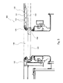
Fig. 5 ,PTL 1 discloses arailcar 100 configured such that both end portions of aside sliding door 120 are respectively pressed, viarubber seals 150, against adoor pocket post 130 and adoor stop post 140 respectively provided at both sides of aside entrance 110. - To secure the airtightness, the
door pocket post 130 has to have relatively high stiffness. Thedoor pocket post 130 has a double skin structure that is flat in a car-longitudinal direction. Specifically, thedoor pocket post 130 is configured such that anouter portion 131 and aninner portion 132 are coupled to each other bycoupling portions 133. According to therailcar 100 disclosed inPTL 1, anedge portion 135, extending along theside entrance 110, of thedoor pocket post 130 is located outwardly of theinner portion 132 in a car-width direction, and arubber seal 150 is attached to theedge portion 135. - PTL 1: Japanese Laid-Open Patent Application Publication No.
2001-58568 - In the case of using the
door pocket post 130 having the double skin structure, because of the thickness of thedoor pocket post 130, theinner portion 132 gets close to theside sliding door 120 when theside sliding door 120 is pulled into a door pocket space adjacent to theinner portion 132. To satisfactorily perform the operation of pulling theside sliding door 120 into the door pocket space, a certain clearance needs to be secured between theside sliding door 120 and a bodyshell (the door pocket post 130) over the entire surface of theinner portion 132. Therefore, in a case where the clearance between theside sliding door 120 and thedoor pocket post 130 is narrow, the clearance needs to be increased. - Normally, the
side sliding door 120 and the bodyshell including thedoor pocket post 130 are separately manufactured. Therefore, the above operation of adjusting the clearance is performed in a step of incorporating theside sliding door 120 in the bodyshell after the bodyshell is manufactured. For example, the operation of adjusting the clearance for satisfactorily pulling the side sliding door into the door pocket space is performed in such a manner that the clearance between thedoor pocket post 130 and theside sliding door 120 is increased to become equal to or larger than a certain value over the entire surface of theinner portion 132 by, for example, heating an area, including thedoor pocket post 130, of the bodyshell while pressing thedoor pocket post 130 by a hydraulic jack or the like. - In addition to the above adjusting operation, in order to secure the airtightness, it is also necessary to adjust the clearance between the side sliding door and the bodyshell before the
side sliding door 120 is pressed against theedge portion 135 at the time of a door closed state (hereinafter may be referred to as "at the time of a closed state"). To be specific, theside sliding door 120 and the bodyshell require both the operation of adjusting the clearance for satisfactorily pulling theside sliding door 120 into the door pocket space and the operation of adjusting the clearance for securing the airtightness at the time of the door closed state. - A problem of the conventional railcar is that it requires a lot of labor and time to adjust the clearance between the side sliding door and the bodyshell as above.
- Here, an object of the present invention is to provide a railcar capable of reducing an operation of adjusting a clearance between a side sliding door and a bodyshell, and a door pocket post suitable for this railcar.
- To solve the above problem, a railcar of the present invention includes: a side entrance peripheral member including a door pocket post and surrounding a side entrance, the door pocket post having a double skin structure in which an outer portion and an inner portion are coupled to each other by a coupling portion , the inner portion being provided inwardly of the outer portion in a car-width direction; and a side sliding door including a peripheral portion that is pressed against an edge portion, extending along the side entrance, of the side entrance peripheral member via a rubber seal at the time of a closed state of the side entrance, the side sliding door being pulled into a door pocket space, adjacent to the inner portion of the door pocket post, at the time of an open state of the side entrance, wherein a projecting portion projecting inwardly in the car-width direction beyond the inner portion and including a tip end that contacts the rubber seal is provided at at least a part of a region constituted by an upper edge and lower edge of the edge portion of the side entrance peripheral member and a lateral edge, located at the door pocket post side, of the edge portion of the side entrance peripheral member.
- According to the above configuration, the projecting portion that contacts the rubber seal is provided at the edge portion of the side entrance peripheral member. Therefore, the clearance (clearance for satisfactorily pulling the side sliding door into the door pocket space) between the inner portion of the door pocket post and the side sliding door becomes larger than the clearance (clearance for securing the airtightness) between the projecting portion and the side sliding door. On this account, the operation of adjusting the clearance is required only at a narrow range corresponding to the projecting portion. Thus, the operation of adjusting the clearance between the side sliding door and the bodyshell can be reduced.
- A door pocket post of the present invention is a door pocket post provided at one side of a side entrance of a railcar and includes: an outer portion; an inner portion provided inwardly of the outer portion in a car-width direction; a coupling portion coupling the outer portion and the inner portion; a vertical bar portion where an end portion, located at the side entrance side, of the outer portion and an end portion, located at the side entrance side, of the inner portion converge; and a projecting portion provided at the vertical bar portion and projecting inwardly in the car-width direction beyond the inner portion.
- The present invention can provide a railcar capable of reducing an operation of adjusting a clearance between a side sliding door and a bodyshell, and a door pocket post suitable for this railcar.
-
-
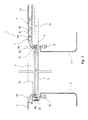
Fig. 1 is a cross-sectional view of structures around a side entrance of a railcar according to one embodiment of the present invention. -
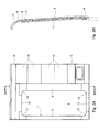
Fig. 2A is a diagram showing a bodyshell around the side entrance, when viewed from an inner side in a car-width direction.Fig. 2B is a cross-sectional view taken along line IIB-IIB ofFig. 2A . -
Fig. 3 is an enlarged view of major components ofFig. 1 . -
Fig. 4 is a cross-sectional view of a door pocket post of Modification Example. -
Fig. 5 is a cross-sectional view showing the structures around the side entrance of the conventional railcar. - Hereinafter, an embodiment of the present invention will be explained in reference to the drawings.
-
Fig. 1 shows arailcar 1 according to one embodiment of the present invention. Therailcar 1 includes: a side entranceperipheral member 7 surrounding aside entrance 2; and aside sliding door 3 configured to open and close theside entrance 2. InFig. 1 , a left-right direction corresponds to a car-longitudinal direction, and an upper-lower direction corresponds to a car-width direction. - As shown in
Fig. 2A , theside entrance 2 has a vertically long, substantially rectangular shape. The side entranceperipheral member 7 includes a frame-shaped edge portion extending along theside entrance 2. Specifically, the side entranceperipheral member 7 includes: adoor stop post 5 and adoor pocket post 6 respectively provided at left and right sides of theside entrance 2; alintel member 16 provided at an upper side of theside entrance 2; and adoorsill member 17 provided at a lower side of theside entrance 2. Further, the side entranceperipheral member 7 includes: fixedside corner members 13 respectively provided between thedoor stop post 5 and thelintel member 16 and between thedoor stop post 5 and thedoorsill member 17; and movableside corner members 14 respectively provided between thedoor pocket post 6 and thelintel member 16 and between thedoor pocket post 6 and thedoorsill member 17. Thecorner members side entrance 2. - However, the configuration of the side entrance
peripheral member 7 is not limited to the configuration shown inFig. 2A . For example, instead of providing the movableside corner member 14 located at the lower side, thedoor pocket post 6 may be joined to a side sill constituting an underframe. Or, instead of providing the movableside corner member 14 located at the upper side, thedoor pocket post 6 may be joined to thelintel member 16 or acantrail 18. - As shown in
Fig. 2B , each of thedoor pocket post 6 and thedoor stop post 5 extends in the upper-lower direction while slightly curving along the contours of therailcar 1 in the car-width direction. Thedoor pocket post 6 and thedoor stop post 5 are members formed by extrusion and are provided such that an extrusion direction corresponds to its longitudinal direction. - A plurality of
shape members 15 each extending in the car-longitudinal direction are lined up in the upper-lower direction so as to be located at a side of thedoor pocket post 6, the side being opposite to a side where theside entrance 2 is provided. Theshape members 15 and thedoor pocket post 6 are joined to one another by welding. Thedoor pocket post 6 and theshape members 15 covers, from an outer side in the car-width direction, a door pocket space 10 (seeFig. 1 ) into which theside sliding door 3 is pulled. - Referring again to
Fig. 1 , a pair ofcovers 11 that form a passage extending from a car-inner space to theside entrance 2 are provided inwardly of theside sliding door 3 in the car-width direction. Each of thecovers 11 has a substantially U-shaped cross section, and the U shapes of thecovers 11 are open in directions opposite to each other. Thecover 11 located at thedoor pocket post 6 side separates thedoor pocket space 10 from the car-inner space and the passage, and astopper 30 is provided between thecover 11 located at thedoor stop post 5 side and thedoor stop post 5 such that theside sliding door 3 contacts thestopper 30 to stop. - The
door pocket post 6 and the door stoppost 5 respectively includevertical bar portions side entrance 2. Each of outer surfaces of thevertical bar portions side entrance 2. Each of thevertical bar portions side entrance 2. Thevertical bar portion 64 of thedoor pocket post 6 and portions of the movableside corner members 14 constitute one of lateral edges of the edge portion of the side entranceperipheral member 7, each of the portions being located at thedoor pocket post 6 side of an intermediate point of a circular-arc portion of the movableside corner member 14. Thevertical bar portion 51 of the door stoppost 5 and portions of the fixedside corner members 13 constitute the other lateral edge of the edge portion of the side entranceperipheral member 7, each of the portions being located at the door stoppost 5 side of the intermediate point of the circular-arc portion of the fixedside corner member 13. A lower portion of thelintel member 16, a portion of thecorner member 13 located at the upper side, and a portion of thecorner member 14 located at the upper side constitute an upper edge of the edge portion of the side entranceperipheral member 7, the portion of thecorner member 13 being located at thelintel member 16 side of the intermediate point of the circular-arc portion of thecorner member 13, the portion of thecorner member 14 being located at thelintel member 16 side of the intermediate point of the circular-arc portion of thecorner member 14. An upper portion of thedoorsill member 17, a portion of thecorner member 13 located at the lower side, and a portion of thecorner member 14 located at the lower side constitute a lower edge of the edge portion of the side entranceperipheral member 7, the portion of thecorner member 13 being located at thedoorsill member 17 side of the intermediate point of the circular-arc portion of thecorner member 13, the portion of thecorner member 14 being located at thedoorsill member 17 side of the intermediate point of the circular-arc portion of thecorner member 14. - The
side sliding door 3 has a vertically long, rectangular shape slightly larger than theside entrance 2. Theside sliding door 3 is moved by a driving unit, not shown, along the car-longitudinal direction between a closed position where both width direction end portions of theside sliding door 3 respectively overlap thevertical bar portion 64 of thedoor pocket post 6 and theedge portion 51 of the door stoppost 5 and an open position where theside sliding door 3 is opposed to thedoor pocket post 6 and theshape members 15. To be specific, when theside sliding door 3 is moved to the closed position, it closes theside entrance 2, and when theside sliding door 3 is moved to the open position, it is pulled into thedoor pocket space 10 to open theside entrance 2. Acontact member 35 configured to contact thestopper 30 when theside sliding door 3 is moved to the closed position is attached to an end surface of theside sliding door 3, the end surface being located at the door stoppost 5 side. - In the present embodiment, an
annular rubber seal 4 along a peripheral portion of theside sliding door 3 is attached to the peripheral portion. Specifically, astep portion 31 is formed at the peripheral portion of theside sliding door 3. Thestep portion 31 is depressed inwardly in the car-width direction from amain surface 3a, facing outwardly in the car-width direction, of theside sliding door 3. Therubber seal 4 is fixed to thestep portion 31. -
Cylinders 12 are respectively provided in spaces respectively surrounded by thecovers 11. At the time of the closed state of theside entrance 2, thecylinders 12 are used for the purpose of pressing the peripheral portion of theside sliding door 3 via therubber seal 4 against the edge portion, extending along theside entrance 2, of the side entranceperipheral member 7. Thecylinders 12 may be provided such that rods thereof extend and contract in the car-width direction to allow thecylinders 12 to directly push both width direction end portions of theside sliding door 3 or such that the rods thereof extend and contract in the upper-lower direction to allow thecylinders 12 to push both end portions of theside sliding door 3 via link mechanisms. - It should be noted that the peripheral portion of the
side sliding door 3 does not necessarily have to be pressed against the edge portion of the side entranceperipheral member 7 via therubber seal 4 over the entire periphery. For example, therubber seal 4 may have an inverted U shape that is open downward, and the peripheral portion of theside sliding door 3 may be pressed against the lateral edges and upper edge of the edge portion of theside entrance 7. - Next, the configuration of the
door pocket post 6 will be explained in more detail in reference toFig. 3 . - The
door pocket post 6 has a double skin structure that is flat in the car-longitudinal direction. Specifically, thedoor pocket post 6 includes: anouter portion 61 facing outwardly in the width direction; and aninner portion 62 provided inwardly of theouter portion 61 in the car-width direction. Theouter portion 61 and theinner portion 62 are coupled to each other by a plurality ofcoupling portions 63. In other words, voids are secured between theouter portion 61 and theinner portion 62 by thecoupling portions 63. - The
inner portion 62 is linearly connected to thevertical bar portion 64. In contrast, an end portion, located at theside entrance 2 side, of theouter portion 61 is bent inwardly in the car-width direction so as to form an inclined surface that is continuous with the outer surface of thevertical bar portion 64. In other words, thevertical bar portion 64 is a portion where an end portion, located at theside entrance 2 side, of theinner portion 62 and the end portion, located at theside entrance 2 side, of theouter portion 61 converge. It should be noted that theinner portion 62 does not necessarily have to be linear over the entire width. For example, as shown inFig. 4 , the end portion, located at theside entrance 2 side, of theinner portion 62 may be bent outwardly in the car-width direction. - A projecting
portion 65 projecting inwardly in the car-width direction beyond theinner portion 62 is provided at a region of thevertical bar portion 64, the region corresponding to therubber seal 4 when theside sliding door 3 is moved to the closed position. To be specific, when theside sliding door 3 is pushed by the cylinder 12 (seeFig. 1 ) as shown by an arrow C inFig. 3 , a tip end of the projectingportion 65 contacts therubber seal 4. - A clearance A between the
side sliding door 3 and the projectingportion 65 of thedoor pocket post 6 before the peripheral portion of theside sliding door 3 is pressed against the edge portion of the side entranceperipheral member 7 at the time of the closed state of theside entrance 2 is smaller than a clearance B between theside sliding door 3 and theinner portion 62 of thedoor pocket post 6 at the time of the open state of theside entrance 2. In other words, the clearance B for satisfactorily pulling theside sliding door 3 into the door pocket space is larger than the clearance A for securing the airtightness. - According to conventional structures, when adjusting the clearance between the
side sliding door 3 and the side entranceperipheral member 7, the value of the clearance A and the value of the clearance B are substantially equal to each other. Therefore, the adjustment of the clearance needs to be performed over a wide range of theinner portion 62 of thedoor pocket post 6. On this account, this operation requires a lot of labor and time. However, according to therailcar 1 of the present embodiment, the operation of adjusting the clearance is required only at a narrow range corresponding to the projecting portion 65 (for example, an operation of cutting the projecting portion 65). Therefore, the operation of adjusting the clearance between theside sliding door 3 and the bodyshell can be reduced. - The
rubber seal 4 may be attached to the edge portion of the side entranceperipheral member 7. However, in this case, thelarge cover 11 shown inFig. 1 and the like need to be detached at the time of the replacement of therubber seal 4. Therefore, this replacement operation requires a lot of labor. In contrast, in a case where therubber seal 4 is attached to the peripheral portion of theside sliding door 3 as in the present embodiment, therubber seal 4 can be replaced only by, for example, detaching the contact member 35 (seeFig. 1 ) and moving theside sliding door 3. To be specific, according to the railcar of the present embodiment, the ease of maintenance can be improved. - Further, according to the present embodiment, the
step portion 31 to which therubber seal 4 is fixed is formed at the peripheral portion of theside sliding door 3. Therefore, at the time of the closed state of theside entrance 2, therubber seal 4 is not exposed so much from between thevertical bar portion 64 of thedoor pocket post 6 and theside sliding door 3. In contrast, in a case where thestep portion 31 is not formed, therubber seal 4 is largely exposed from between thevertical bar portion 64 of thedoor pocket post 6 and theside sliding door 3, so that a cover for therubber seal 4 is required. To be specific, in a case where thestep portion 31 is formed as in the present embodiment, the number of parts can be reduced. - According to the present embodiment, the projecting
portion 65 projecting inwardly in the car-width direction beyond theinner portion 62 is provided at thedoor pocket post 6. However, the present invention is not limited to this. The projectingportion 65 may be provided at a component (thelintel member 16, thedoorsill member 17, or thecorner member 13 or 14) other than thedoor pocket post 6 of the side entranceperipheral member 7. To be specific, the projectingportion 65 is only required to be provided at at least a part of a substantially U-shaped region constituted by an upper edge and lower edge of the edge portion, extending along theside entrance 2, of the side entranceperipheral member 7 and a lateral edge, located at thedoor pocket post 6 side, of the edge portion of the side entranceperipheral member 7. It should be noted that in a case where the projectingportion 65 is provided at thevertical bar portion 64 of thedoor pocket post 6 as in the present embodiment, satisfactory airtightness can be obtained as compared to a case where the projectingportion 65 is provided at thelintel member 16 or thedoorsill member 17. The projectingportion 65 as a separate member may constitute the side entranceperipheral member 7 instead of being integrated with thedoor pocket post 6 and the like. - The above-described railcar includes: a side entrance peripheral member including a door pocket post and surrounding a side entrance, the door pocket post having a double skin structure in which an outer portion and an inner portion are coupled to each other by a coupling portion , the inner portion being provided inwardly of the outer portion in a car-width direction; and a side sliding door including a peripheral portion that is pressed against an edge portion, extending along the side entrance, of the side entrance peripheral member via a rubber seal at the time of a closed state of the side entrance, the side sliding door being pulled into a door pocket space, adjacent to the inner portion of the door pocket post, at the time of an open state of the side entrance, wherein a projecting portion projecting inwardly in the car-width direction beyond the inner portion and including a tip end that contacts the rubber seal is provided at at least a part of a region constituted by an upper edge and lower edge of the edge portion of the side entrance peripheral member and a lateral edge, located at the door pocket post side, of the edge portion of the side entrance peripheral member.
- According to this configuration, the projecting portion that contacts the rubber seal is provided at the edge portion of the side entrance peripheral member. Therefore, the clearance (clearance for satisfactorily pulling the side sliding door into the door pocket space) between the inner portion of the door pocket post and the side sliding door becomes larger than the clearance (clearance for securing the airtightness) between the projecting portion and the side sliding door. On this account, the operation of adjusting the clearance is required only at the narrow range corresponding to the projecting portion. Thus, the operation of adjusting the clearance between the side sliding door and the bodyshell can be reduced.
- According to the above-described railcar, a clearance between the side sliding door and the projecting portion before the peripheral portion of the side sliding door is pressed against the edge portion at the time of the closed state of the side entrance is smaller than a clearance between the side sliding door and the inner portion of the door pocket post at the time of the open state of the side entrance.
- According to the above-described railcar, the door pocket post includes a vertical bar portion where an end portion, located at the side entrance side, of the outer portion and an end portion, located at the side entrance side, of the inner portion converge, and the projecting portion is provided at the vertical bar portion. Therefore, the satisfactory airtightness can be obtained.
- According to the above-described railcar, the rubber seal is attached to the peripheral portion of the side sliding door. Therefore, the ease of maintenance can be improved.
- According to the above-described railcar, a step portion is formed at the peripheral portion of the side sliding door, the step portion being depressed inwardly in the car-width direction from a main surface, facing outwardly in the car-width direction, of the side sliding door, and the rubber seal is fixed to the step portion. Therefore, the number of parts can be reduced.
- The foregoing has explained the embodiment of the present invention in reference to the drawings. However, the specific configurations of the present invention are not limited to the above embodiment. Design changes and the like may be made within the scope of the present invention.
-
- 1
- railcar
- 10
- door pocket space
- 2
- side entrance
- 3
- side sliding door
- 4
- rubber seal
- 6
- door pocket post
- 61
- outer portion
- 62
- inner portion
- 63
- coupling portion
- 64
- vertical bar portion
- 65
- projecting portion
- 7
- side entrance peripheral member
Claims (6)
- A railcar comprising:a side entrance peripheral member including a door pocket post and surrounding a side entrance, the door pocket post having a double skin structure in which an outer portion and an inner portion are coupled to each other by a coupling portion, the inner portion being provided inwardly of the outer portion in a car-width direction; anda side sliding door including a peripheral portion that is pressed against an edge portion, extending along the side entrance, of the side entrance peripheral member via a rubber seal at the time of a closed state of the side entrance, the side sliding door being pulled into a door pocket space, adjacent to the inner portion of the door pocket post, at the time of an open state of the side entrance, whereina projecting portion projecting inwardly in the car-width direction beyond the inner portion and including a tip end that contacts the rubber seal is provided at at least a part of a region constituted by an upper edge and lower edge of the edge portion of the side entrance peripheral member and a lateral edge, located at the door pocket post side, of the edge portion of the side entrance peripheral member.
- The railcar according to claim 1, wherein a clearance between the side sliding door and the projecting portion before the peripheral portion of the side sliding door is pressed against the edge portion at the time of the closed state of the side entrance is smaller than a clearance between the side sliding door and the inner portion of the door pocket post at the time of the open state of the side entrance.
- The railcar according to claim 1 or 2, wherein:the door pocket post includes a vertical bar portion where an end portion, located at the side entrance side, of the outer portion and an end portion, located at the side entrance side, of the inner portion converge; andthe projecting portion is provided at the vertical bar portion.
- The railcar according to any one of claims 1 to 3, wherein the rubber seal is attached to the peripheral portion of the side sliding door.
- The railcar according to claim 4, wherein:a step portion is formed at the peripheral portion of the side sliding door, the step portion being depressed inwardly in the car-width direction from a main surface, facing outwardly in the car-width direction, of the side sliding door; andthe rubber seal is fixed to the step portion.
- A door pocket post provided at one side of a side entrance of a railcar,
the door pocket post comprising:an outer portion;an inner portion provided inwardly of the outer portion in the car-width direction;a coupling portion coupling the outer portion and the inner portion;a vertical bar portion where an end portion, located at the side entrance side, of the outer portion and an end portion, located at the side entrance side, of the inner portion converge; anda projecting portion provided at the vertical bar portion and projecting inwardly in the car-width direction beyond the inner portion.
Applications Claiming Priority (2)
| Application Number | Priority Date | Filing Date | Title |
|---|---|---|---|
| JP2012133783A JP5926627B2 (en) | 2012-06-13 | 2012-06-13 | Rail vehicles and door pockets |
| PCT/JP2013/003668 WO2013187051A1 (en) | 2012-06-13 | 2013-06-11 | Rail car and door bag column |
Publications (3)
| Publication Number | Publication Date |
|---|---|
| EP2862774A1 true EP2862774A1 (en) | 2015-04-22 |
| EP2862774A4 EP2862774A4 (en) | 2016-03-02 |
| EP2862774B1 EP2862774B1 (en) | 2019-08-14 |
Family
ID=49757896
Family Applications (1)
| Application Number | Title | Priority Date | Filing Date |
|---|---|---|---|
| EP13804416.9A Active EP2862774B1 (en) | 2012-06-13 | 2013-06-11 | Railcar and door pocket post |
Country Status (7)
| Country | Link |
|---|---|
| US (1) | US9849891B2 (en) |
| EP (1) | EP2862774B1 (en) |
| JP (1) | JP5926627B2 (en) |
| CN (1) | CN104284826B (en) |
| IN (1) | IN2014KN02805A (en) |
| TW (1) | TWI531501B (en) |
| WO (1) | WO2013187051A1 (en) |
Families Citing this family (4)
| Publication number | Priority date | Publication date | Assignee | Title |
|---|---|---|---|---|
| JP5926627B2 (en) * | 2012-06-13 | 2016-05-25 | 川崎重工業株式会社 | Rail vehicles and door pockets |
| DE202014104110U1 (en) * | 2014-09-02 | 2014-09-16 | Knorr-Bremse Gmbh | Door seal device, door seal system and door leaf for a rail vehicle |
| JP6887237B2 (en) * | 2016-11-04 | 2021-06-16 | 株式会社日立製作所 | Railroad vehicle structure |
| JP2021098394A (en) * | 2019-12-20 | 2021-07-01 | 西日本旅客鉄道株式会社 | Railway vehicle |
Family Cites Families (19)
| Publication number | Priority date | Publication date | Assignee | Title |
|---|---|---|---|---|
| AU655250B2 (en) * | 1991-04-26 | 1994-12-08 | Hitachi Limited | Vehicle and method of producing the same |
| JP3041523U (en) * | 1997-03-17 | 1997-09-22 | 東海交通機械株式会社 | Door mechanism for empty can exclusion weir and rail car entrance / exit |
| US6302031B1 (en) * | 1998-05-20 | 2001-10-16 | Trn Business Trust | Sidewall for a railway car |
| JP2000344096A (en) * | 1999-06-07 | 2000-12-12 | Kawasaki Heavy Ind Ltd | Elevating doors for high-speed rail vehicles |
| JP3509651B2 (en) | 1999-08-20 | 2004-03-22 | 日本車輌製造株式会社 | Step shape on the body side surface of a high-speed vehicle |
| JP4234369B2 (en) * | 2002-08-02 | 2009-03-04 | 日本車輌製造株式会社 | Snow prevention device for sliding door for vehicle |
| US7004080B2 (en) * | 2003-10-09 | 2006-02-28 | Trn Business Trust | Boxcar with load restraint system |
| KR100850099B1 (en) * | 2004-05-18 | 2008-08-04 | 카와사키 주코교 카부시키 카이샤 | Structure for rolling stock |
| JP4435631B2 (en) * | 2004-06-30 | 2010-03-24 | 東海旅客鉄道株式会社 | Railway vehicle having side sliding door device |
| US20070284913A1 (en) * | 2006-06-09 | 2007-12-13 | Ehrlich Rodney P | Wall Construction For A Trailer |
| WO2008068796A1 (en) * | 2006-11-30 | 2008-06-12 | The Kinki Sharyo Co., Ltd. | Body skeleton structure of rolling stock |
| WO2008068860A1 (en) * | 2006-12-06 | 2008-06-12 | The Kinki Sharyo Co., Ltd. | Body skeleton structure of rolling stock |
| CN201179873Y (en) * | 2007-12-20 | 2009-01-14 | 南车四方机车车辆股份有限公司 | Door frame structure of railway vehicle door |
| CN201214417Y (en) | 2008-05-16 | 2009-04-01 | 南车四方机车车辆股份有限公司 | Rail vehicle outside airtight door |
| JP5114327B2 (en) * | 2008-07-21 | 2013-01-09 | 日本車輌製造株式会社 | Railway vehicle |
| US8707873B2 (en) * | 2009-03-25 | 2014-04-29 | West Japan Railway Company | Bodyshell structure of railcar |
| JP5204082B2 (en) * | 2009-12-16 | 2013-06-05 | 株式会社日立製作所 | Rail vehicle |
| JP5759712B2 (en) * | 2010-12-14 | 2015-08-05 | 川崎重工業株式会社 | Rail vehicle interior mounting structure |
| JP5926627B2 (en) * | 2012-06-13 | 2016-05-25 | 川崎重工業株式会社 | Rail vehicles and door pockets |
-
2012
- 2012-06-13 JP JP2012133783A patent/JP5926627B2/en active Active
-
2013
- 2013-06-11 IN IN2805KON2014 patent/IN2014KN02805A/en unknown
- 2013-06-11 WO PCT/JP2013/003668 patent/WO2013187051A1/en not_active Ceased
- 2013-06-11 US US14/408,170 patent/US9849891B2/en active Active
- 2013-06-11 CN CN201380026077.XA patent/CN104284826B/en not_active Expired - Fee Related
- 2013-06-11 EP EP13804416.9A patent/EP2862774B1/en active Active
- 2013-06-13 TW TW102120838A patent/TWI531501B/en active
Also Published As
| Publication number | Publication date |
|---|---|
| TWI531501B (en) | 2016-05-01 |
| JP2013256214A (en) | 2013-12-26 |
| CN104284826B (en) | 2016-11-09 |
| JP5926627B2 (en) | 2016-05-25 |
| IN2014KN02805A (en) | 2015-05-08 |
| CN104284826A (en) | 2015-01-14 |
| US9849891B2 (en) | 2017-12-26 |
| EP2862774B1 (en) | 2019-08-14 |
| EP2862774A4 (en) | 2016-03-02 |
| TW201404637A (en) | 2014-02-01 |
| US20150135987A1 (en) | 2015-05-21 |
| WO2013187051A1 (en) | 2013-12-19 |
Similar Documents
| Publication | Publication Date | Title |
|---|---|---|
| EP2862774B1 (en) | Railcar and door pocket post | |
| KR102138043B1 (en) | Blank, and method for producing press-molded article | |
| US9914482B2 (en) | Vehicle side structure | |
| CN101412361B (en) | Open roof construction | |
| CN105102309A (en) | Automobile body lateral-portion structure | |
| DE102007036366A1 (en) | Vehicle roof with a roof module | |
| CN109863049A (en) | skylight unit | |
| DE102014217917B4 (en) | Door construction for a vehicle | |
| US20190030586A1 (en) | Method of manufacturing skeleton member for vehicle | |
| CN203439886U (en) | Door device of elevator | |
| CN104487373B (en) | elevator equipment | |
| JP6137095B2 (en) | Vehicle side body structure | |
| JP6012619B2 (en) | Airtight device in elevator car and elevator car with airtight device | |
| JP6022689B2 (en) | Elevator cab | |
| JP6347484B2 (en) | Rail vehicle cab frame frame and gutter structure | |
| JP2010126069A (en) | Vehicle door | |
| CN106006327B (en) | Lift appliance | |
| CN106470933A (en) | The doorway device of elevator | |
| CN105082951B (en) | The system and composite component of frame part and composite component including door-window | |
| KR101757803B1 (en) | Structure of doorroom for protecting outdoor of doorguideshoe | |
| US20210260974A1 (en) | Vehicle entrance structure | |
| KR101697763B1 (en) | Structure of doorroom for protecting outdoor of doorguideshoe | |
| JP2015009771A (en) | Door structure | |
| JP6001510B2 (en) | Telescopic cover | |
| JP2014065394A (en) | Glass run |
Legal Events
| Date | Code | Title | Description |
|---|---|---|---|
| PUAI | Public reference made under article 153(3) epc to a published international application that has entered the european phase |
Free format text: ORIGINAL CODE: 0009012 |
|
| 17P | Request for examination filed |
Effective date: 20141210 |
|
| AK | Designated contracting states |
Kind code of ref document: A1 Designated state(s): AL AT BE BG CH CY CZ DE DK EE ES FI FR GB GR HR HU IE IS IT LI LT LU LV MC MK MT NL NO PL PT RO RS SE SI SK SM TR |
|
| AX | Request for extension of the european patent |
Extension state: BA ME |
|
| RIN1 | Information on inventor provided before grant (corrected) |
Inventor name: WAKI, KENJI Inventor name: INABA, KAZUMASA Inventor name: OKADA, SHINICHI Inventor name: KAWAKAMI, NAOAKI Inventor name: YOSHIDA, NAOHIRO |
|
| DAX | Request for extension of the european patent (deleted) | ||
| RA4 | Supplementary search report drawn up and despatched (corrected) |
Effective date: 20160128 |
|
| RIC1 | Information provided on ipc code assigned before grant |
Ipc: B61D 17/08 20060101ALI20160122BHEP Ipc: B61D 19/02 20060101ALI20160122BHEP Ipc: B61D 19/00 20060101AFI20160122BHEP |
|
| GRAP | Despatch of communication of intention to grant a patent |
Free format text: ORIGINAL CODE: EPIDOSNIGR1 |
|
| STAA | Information on the status of an ep patent application or granted ep patent |
Free format text: STATUS: GRANT OF PATENT IS INTENDED |
|
| INTG | Intention to grant announced |
Effective date: 20190124 |
|
| GRAS | Grant fee paid |
Free format text: ORIGINAL CODE: EPIDOSNIGR3 |
|
| GRAA | (expected) grant |
Free format text: ORIGINAL CODE: 0009210 |
|
| STAA | Information on the status of an ep patent application or granted ep patent |
Free format text: STATUS: THE PATENT HAS BEEN GRANTED |
|
| AK | Designated contracting states |
Kind code of ref document: B1 Designated state(s): AL AT BE BG CH CY CZ DE DK EE ES FI FR GB GR HR HU IE IS IT LI LT LU LV MC MK MT NL NO PL PT RO RS SE SI SK SM TR |
|
| REG | Reference to a national code |
Ref country code: GB Ref legal event code: FG4D |
|
| REG | Reference to a national code |
Ref country code: CH Ref legal event code: EP Ref country code: AT Ref legal event code: REF Ref document number: 1166674 Country of ref document: AT Kind code of ref document: T Effective date: 20190815 |
|
| REG | Reference to a national code |
Ref country code: DE Ref legal event code: R096 Ref document number: 602013059235 Country of ref document: DE |
|
| REG | Reference to a national code |
Ref country code: IE Ref legal event code: FG4D |
|
| REG | Reference to a national code |
Ref country code: NL Ref legal event code: MP Effective date: 20190814 |
|
| REG | Reference to a national code |
Ref country code: LT Ref legal event code: MG4D |
|
| PG25 | Lapsed in a contracting state [announced via postgrant information from national office to epo] |
Ref country code: FI Free format text: LAPSE BECAUSE OF FAILURE TO SUBMIT A TRANSLATION OF THE DESCRIPTION OR TO PAY THE FEE WITHIN THE PRESCRIBED TIME-LIMIT Effective date: 20190814 Ref country code: PT Free format text: LAPSE BECAUSE OF FAILURE TO SUBMIT A TRANSLATION OF THE DESCRIPTION OR TO PAY THE FEE WITHIN THE PRESCRIBED TIME-LIMIT Effective date: 20191216 Ref country code: HR Free format text: LAPSE BECAUSE OF FAILURE TO SUBMIT A TRANSLATION OF THE DESCRIPTION OR TO PAY THE FEE WITHIN THE PRESCRIBED TIME-LIMIT Effective date: 20190814 Ref country code: BG Free format text: LAPSE BECAUSE OF FAILURE TO SUBMIT A TRANSLATION OF THE DESCRIPTION OR TO PAY THE FEE WITHIN THE PRESCRIBED TIME-LIMIT Effective date: 20191114 Ref country code: SE Free format text: LAPSE BECAUSE OF FAILURE TO SUBMIT A TRANSLATION OF THE DESCRIPTION OR TO PAY THE FEE WITHIN THE PRESCRIBED TIME-LIMIT Effective date: 20190814 Ref country code: NL Free format text: LAPSE BECAUSE OF FAILURE TO SUBMIT A TRANSLATION OF THE DESCRIPTION OR TO PAY THE FEE WITHIN THE PRESCRIBED TIME-LIMIT Effective date: 20190814 Ref country code: NO Free format text: LAPSE BECAUSE OF FAILURE TO SUBMIT A TRANSLATION OF THE DESCRIPTION OR TO PAY THE FEE WITHIN THE PRESCRIBED TIME-LIMIT Effective date: 20191114 Ref country code: LT Free format text: LAPSE BECAUSE OF FAILURE TO SUBMIT A TRANSLATION OF THE DESCRIPTION OR TO PAY THE FEE WITHIN THE PRESCRIBED TIME-LIMIT Effective date: 20190814 |
|
| REG | Reference to a national code |
Ref country code: AT Ref legal event code: MK05 Ref document number: 1166674 Country of ref document: AT Kind code of ref document: T Effective date: 20190814 |
|
| PG25 | Lapsed in a contracting state [announced via postgrant information from national office to epo] |
Ref country code: ES Free format text: LAPSE BECAUSE OF FAILURE TO SUBMIT A TRANSLATION OF THE DESCRIPTION OR TO PAY THE FEE WITHIN THE PRESCRIBED TIME-LIMIT Effective date: 20190814 Ref country code: AL Free format text: LAPSE BECAUSE OF FAILURE TO SUBMIT A TRANSLATION OF THE DESCRIPTION OR TO PAY THE FEE WITHIN THE PRESCRIBED TIME-LIMIT Effective date: 20190814 Ref country code: LV Free format text: LAPSE BECAUSE OF FAILURE TO SUBMIT A TRANSLATION OF THE DESCRIPTION OR TO PAY THE FEE WITHIN THE PRESCRIBED TIME-LIMIT Effective date: 20190814 Ref country code: IS Free format text: LAPSE BECAUSE OF FAILURE TO SUBMIT A TRANSLATION OF THE DESCRIPTION OR TO PAY THE FEE WITHIN THE PRESCRIBED TIME-LIMIT Effective date: 20191214 Ref country code: GR Free format text: LAPSE BECAUSE OF FAILURE TO SUBMIT A TRANSLATION OF THE DESCRIPTION OR TO PAY THE FEE WITHIN THE PRESCRIBED TIME-LIMIT Effective date: 20191115 Ref country code: RS Free format text: LAPSE BECAUSE OF FAILURE TO SUBMIT A TRANSLATION OF THE DESCRIPTION OR TO PAY THE FEE WITHIN THE PRESCRIBED TIME-LIMIT Effective date: 20190814 |
|
| PG25 | Lapsed in a contracting state [announced via postgrant information from national office to epo] |
Ref country code: TR Free format text: LAPSE BECAUSE OF FAILURE TO SUBMIT A TRANSLATION OF THE DESCRIPTION OR TO PAY THE FEE WITHIN THE PRESCRIBED TIME-LIMIT Effective date: 20190814 |
|
| PG25 | Lapsed in a contracting state [announced via postgrant information from national office to epo] |
Ref country code: EE Free format text: LAPSE BECAUSE OF FAILURE TO SUBMIT A TRANSLATION OF THE DESCRIPTION OR TO PAY THE FEE WITHIN THE PRESCRIBED TIME-LIMIT Effective date: 20190814 Ref country code: PL Free format text: LAPSE BECAUSE OF FAILURE TO SUBMIT A TRANSLATION OF THE DESCRIPTION OR TO PAY THE FEE WITHIN THE PRESCRIBED TIME-LIMIT Effective date: 20190814 Ref country code: IT Free format text: LAPSE BECAUSE OF FAILURE TO SUBMIT A TRANSLATION OF THE DESCRIPTION OR TO PAY THE FEE WITHIN THE PRESCRIBED TIME-LIMIT Effective date: 20190814 Ref country code: RO Free format text: LAPSE BECAUSE OF FAILURE TO SUBMIT A TRANSLATION OF THE DESCRIPTION OR TO PAY THE FEE WITHIN THE PRESCRIBED TIME-LIMIT Effective date: 20190814 Ref country code: AT Free format text: LAPSE BECAUSE OF FAILURE TO SUBMIT A TRANSLATION OF THE DESCRIPTION OR TO PAY THE FEE WITHIN THE PRESCRIBED TIME-LIMIT Effective date: 20190814 Ref country code: DK Free format text: LAPSE BECAUSE OF FAILURE TO SUBMIT A TRANSLATION OF THE DESCRIPTION OR TO PAY THE FEE WITHIN THE PRESCRIBED TIME-LIMIT Effective date: 20190814 |
|
| PG25 | Lapsed in a contracting state [announced via postgrant information from national office to epo] |
Ref country code: CZ Free format text: LAPSE BECAUSE OF FAILURE TO SUBMIT A TRANSLATION OF THE DESCRIPTION OR TO PAY THE FEE WITHIN THE PRESCRIBED TIME-LIMIT Effective date: 20190814 Ref country code: SK Free format text: LAPSE BECAUSE OF FAILURE TO SUBMIT A TRANSLATION OF THE DESCRIPTION OR TO PAY THE FEE WITHIN THE PRESCRIBED TIME-LIMIT Effective date: 20190814 Ref country code: SM Free format text: LAPSE BECAUSE OF FAILURE TO SUBMIT A TRANSLATION OF THE DESCRIPTION OR TO PAY THE FEE WITHIN THE PRESCRIBED TIME-LIMIT Effective date: 20190814 Ref country code: IS Free format text: LAPSE BECAUSE OF FAILURE TO SUBMIT A TRANSLATION OF THE DESCRIPTION OR TO PAY THE FEE WITHIN THE PRESCRIBED TIME-LIMIT Effective date: 20200224 |
|
| REG | Reference to a national code |
Ref country code: DE Ref legal event code: R097 Ref document number: 602013059235 Country of ref document: DE |
|
| PLBE | No opposition filed within time limit |
Free format text: ORIGINAL CODE: 0009261 |
|
| STAA | Information on the status of an ep patent application or granted ep patent |
Free format text: STATUS: NO OPPOSITION FILED WITHIN TIME LIMIT |
|
| PG2D | Information on lapse in contracting state deleted |
Ref country code: IS |
|
| 26N | No opposition filed |
Effective date: 20200603 |
|
| PG25 | Lapsed in a contracting state [announced via postgrant information from national office to epo] |
Ref country code: SI Free format text: LAPSE BECAUSE OF FAILURE TO SUBMIT A TRANSLATION OF THE DESCRIPTION OR TO PAY THE FEE WITHIN THE PRESCRIBED TIME-LIMIT Effective date: 20190814 |
|
| PG25 | Lapsed in a contracting state [announced via postgrant information from national office to epo] |
Ref country code: MC Free format text: LAPSE BECAUSE OF FAILURE TO SUBMIT A TRANSLATION OF THE DESCRIPTION OR TO PAY THE FEE WITHIN THE PRESCRIBED TIME-LIMIT Effective date: 20190814 |
|
| REG | Reference to a national code |
Ref country code: CH Ref legal event code: PL |
|
| GBPC | Gb: european patent ceased through non-payment of renewal fee |
Effective date: 20200611 |
|
| PG25 | Lapsed in a contracting state [announced via postgrant information from national office to epo] |
Ref country code: LU Free format text: LAPSE BECAUSE OF NON-PAYMENT OF DUE FEES Effective date: 20200611 |
|
| REG | Reference to a national code |
Ref country code: BE Ref legal event code: MM Effective date: 20200630 |
|
| PG25 | Lapsed in a contracting state [announced via postgrant information from national office to epo] |
Ref country code: IE Free format text: LAPSE BECAUSE OF NON-PAYMENT OF DUE FEES Effective date: 20200611 Ref country code: LI Free format text: LAPSE BECAUSE OF NON-PAYMENT OF DUE FEES Effective date: 20200630 Ref country code: GB Free format text: LAPSE BECAUSE OF NON-PAYMENT OF DUE FEES Effective date: 20200611 Ref country code: CH Free format text: LAPSE BECAUSE OF NON-PAYMENT OF DUE FEES Effective date: 20200630 |
|
| PG25 | Lapsed in a contracting state [announced via postgrant information from national office to epo] |
Ref country code: BE Free format text: LAPSE BECAUSE OF NON-PAYMENT OF DUE FEES Effective date: 20200630 |
|
| PG25 | Lapsed in a contracting state [announced via postgrant information from national office to epo] |
Ref country code: MT Free format text: LAPSE BECAUSE OF FAILURE TO SUBMIT A TRANSLATION OF THE DESCRIPTION OR TO PAY THE FEE WITHIN THE PRESCRIBED TIME-LIMIT Effective date: 20190814 Ref country code: CY Free format text: LAPSE BECAUSE OF FAILURE TO SUBMIT A TRANSLATION OF THE DESCRIPTION OR TO PAY THE FEE WITHIN THE PRESCRIBED TIME-LIMIT Effective date: 20190814 |
|
| REG | Reference to a national code |
Ref country code: DE Ref legal event code: R081 Ref document number: 602013059235 Country of ref document: DE Owner name: KAWASAKI RAILCAR MANUFACTURING CO., LTD., KOBE, JP Free format text: FORMER OWNER: KAWASAKI JUKOGYO KABUSHIKI KAISHA, KOBE-SHI, HYOGO, JP |
|
| PG25 | Lapsed in a contracting state [announced via postgrant information from national office to epo] |
Ref country code: MK Free format text: LAPSE BECAUSE OF FAILURE TO SUBMIT A TRANSLATION OF THE DESCRIPTION OR TO PAY THE FEE WITHIN THE PRESCRIBED TIME-LIMIT Effective date: 20190814 |
|
| PGFP | Annual fee paid to national office [announced via postgrant information from national office to epo] |
Ref country code: DE Payment date: 20240502 Year of fee payment: 12 |
|
| PGFP | Annual fee paid to national office [announced via postgrant information from national office to epo] |
Ref country code: FR Payment date: 20240509 Year of fee payment: 12 |
|
| REG | Reference to a national code |
Ref country code: DE Ref legal event code: R119 Ref document number: 602013059235 Country of ref document: DE |
|
| PG25 | Lapsed in a contracting state [announced via postgrant information from national office to epo] |
Ref country code: DE Free format text: LAPSE BECAUSE OF NON-PAYMENT OF DUE FEES Effective date: 20260101 |
|
| PG25 | Lapsed in a contracting state [announced via postgrant information from national office to epo] |
Ref country code: FR Free format text: LAPSE BECAUSE OF NON-PAYMENT OF DUE FEES Effective date: 20250630 |