EP2862484A1 - Ventilated cold display unit - Google Patents
Ventilated cold display unit Download PDFInfo
- Publication number
- EP2862484A1 EP2862484A1 EP20140187447 EP14187447A EP2862484A1 EP 2862484 A1 EP2862484 A1 EP 2862484A1 EP 20140187447 EP20140187447 EP 20140187447 EP 14187447 A EP14187447 A EP 14187447A EP 2862484 A1 EP2862484 A1 EP 2862484A1
- Authority
- EP
- European Patent Office
- Prior art keywords
- chamber
- air
- duct
- zone
- furniture
- Prior art date
- Legal status (The legal status is an assumption and is not a legal conclusion. Google has not performed a legal analysis and makes no representation as to the accuracy of the status listed.)
- Granted
Links
- 238000001816 cooling Methods 0.000 claims abstract description 6
- 230000002093 peripheral effect Effects 0.000 claims abstract description 3
- 235000013305 food Nutrition 0.000 claims description 5
- 239000011521 glass Substances 0.000 claims description 3
- 230000001681 protective effect Effects 0.000 claims description 3
- 238000004519 manufacturing process Methods 0.000 description 3
- XLYOFNOQVPJJNP-UHFFFAOYSA-N water Substances O XLYOFNOQVPJJNP-UHFFFAOYSA-N 0.000 description 3
- 238000007664 blowing Methods 0.000 description 2
- 238000001035 drying Methods 0.000 description 2
- 239000003595 mist Substances 0.000 description 2
- 239000003507 refrigerant Substances 0.000 description 2
- 230000009286 beneficial effect Effects 0.000 description 1
- 230000008030 elimination Effects 0.000 description 1
- 238000003379 elimination reaction Methods 0.000 description 1
- 239000005457 ice water Substances 0.000 description 1
- 239000000203 mixture Substances 0.000 description 1
- 238000005057 refrigeration Methods 0.000 description 1
- 229920002994 synthetic fiber Polymers 0.000 description 1
Images


Classifications
-
- A—HUMAN NECESSITIES
- A47—FURNITURE; DOMESTIC ARTICLES OR APPLIANCES; COFFEE MILLS; SPICE MILLS; SUCTION CLEANERS IN GENERAL
- A47F—SPECIAL FURNITURE, FITTINGS, OR ACCESSORIES FOR SHOPS, STOREHOUSES, BARS, RESTAURANTS OR THE LIKE; PAYING COUNTERS
- A47F3/00—Show cases or show cabinets
- A47F3/04—Show cases or show cabinets air-conditioned, refrigerated
- A47F3/0482—Details common to both closed and open types
- A47F3/0495—Spraying, trickling or humidifying means
Definitions
- the present invention relates to a cold ventilated display cabinet for the presentation of products such as food products.
- a piece of furniture comprising an air humidifier and at least one open or closed enclosure comprising an upper zone of exposure of the products and a lower technical zone containing at least partially means for forced circulation of the air and means cold production for cooling said air, said zones being separated from each other at least by a presentation tray of the products and communicating with each other at least by a chamber disposed along one of the edges , said rear of the upper exposure zone, and by at least one air intake opening disposed along the opposite opposite edge before the upper exposure zone, said chamber being connected as input to the lower technical zone and at the outlet to the upper exposure zone for a loop circulation of the air between said zones, with a flow of air flowing over the present plateau (s). tion, from the chamber to the air intake opening or openings and a return air flow flowing below the or presentation trays, from the air intake opening or openings to the chamber.
- the air humidifier present to prevent too fast drying of products, especially food, exposed, often causes unwanted water runoff resulting from the size of the droplets and Due to the current design of said furniture, this requires a high blowing speed, which counteracts the beneficial effect on drying out due to the presence of the humidifier.
- the presence of moisture in the air can also cause the setting of ice water at the cooling means of said air.
- An object of the present invention is therefore to provide a display cabinet of the aforementioned type, whose design allows the production of a homogeneous water mist, associated with a low blowing speed.
- the subject of the invention is a ventilated cold display cabinet for the presentation of products, such as food products, the cabinet comprising an air humidifier and at least one open or closed enclosure comprising an upper zone. for exposing the products and a lower technical zone containing at least partially means for forced circulation of the air and means for producing cold with a view to cooling said air, said zones being separated from each other at least by a display tray of the products and communicating with each other at least by a chamber disposed along one of the said rear edges of the upper exposure zone and by at least one air intake opening disposed along the opposite edge, said front, of said upper exposure zone, said chamber being connected at the input, to the lower technical zone, and at the output, to the upper exposure zone, for a circula looping the air between said zones, with a flow of air flowing over the presentation tray or trays from the chamber to the air intake opening or openings, and a return air flow flowing below the presentation tray (s) from the air intake opening (s) to the chamber, characterized in that said chamber contains at least one
- the use of a duct also makes it possible to easily adjust the position of the duct inside said chamber, according to the speed of the air.
- the lateral openings of the conduit open into the chamber at a location above the plane passing through the presentation tray or trays.
- the generation of a homogeneous fog at a location near the exit of the chamber reduces the velocity of the air used as a vector of fog in the exposure zone, compared to a solution in which the fog is produced under the or the exposure trays, as is the case in the state of the art where the production of a large air flow is necessary to drive the fog into the exposure zone.
- the lateral openings of the duct are disposed along the side of the duct opposite to that facing the upper exposure zone.
- This arrangement again allows to discard the largest droplets and any excess water, and facilitate the air / mist mixture.
- the lateral openings of the duct are circular openings with a diameter of preferably between 20 and 25 mm. These lateral openings are preferably arranged in the form of one or more rows of openings along generatrices of said duct.
- the conduit is disposed in said chamber at least partially above the plane passing through the presentation tray (s).
- the duct is disposed substantially axially inside said chamber, that is to say substantially parallel to the rear edge of the upper exposure zone. This arrangement makes it possible to obtain a uniform fog inside the volume of the chamber, over the entire length of the chamber, with a small footprint.
- the conduit is disposed substantially horizontally within said chamber and supported from place to place by supports within the chamber.
- This duct is a cylindrical duct, preferably made of synthetic material, and the openings are formed by perforations of the duct disposed along at least one generatrix of the duct.
- the outlet of the chamber comprises a baffle.
- This baffle capable of creating turbulence, again promotes the elimination of too large droplets.
- one of the walls of the baffle is formed by a perforated grid.
- the chamber is surmounted by a shelf and the so-called front part of the enclosure intended to face the customer and adjoining the front edge of the upper exposure zone is provided with a protective glass, the one or more presentation trays extending inside the enclosure from a position under the shelf towards the front portion of the enclosure.
- the corridor-type chamber comprises a bottom, two vertical walls, substantially parallel, and extending parallel to the rear edge of the upper exposure zone, and a top face, the lower and upper edges of the vertical wall. adjoining the upper exposure zone being respectively spaced from the bottom and the top face of the chamber to delimit, between the bottom edge and the bottom, the entrance of the chamber and, between the upper edge and the top face, the exit of the bedroom.
- the forced air circulation means comprise fans arranged along a line substantially parallel to one of the front or rear edges of the upper exposure zone, at the rate of at least three fans per linear meter.
- In-line positioning and the large number of fans help reduce the blower fan cones to achieve a more even fan speed.
- the forced air circulation means are configured to produce an air flow having a velocity, taken substantially in the middle of the support surface formed by the exposure tray or trays of the exposure zone, less than 0.50 ms -1 .
- the subject of the invention is a ventilated cold display cabinet 1 for the presentation of products, in particular food products.
- This piece of furniture 1 comprises an air humidifier 2 formed here by an ultrasonic humidifier and an enclosure 3.
- This enclosure 3 comprises a 4 upper product exposure area and a lower technical zone containing at least partially means 6 for forced circulation of air and means 7 for producing cold for cooling said air.
- zones 4, 5 are separated from each other by a plurality of trays 8 for presenting the products and communicate with each other by a chamber 9 disposed along one of the edges, called the rear edge 10 of the upper zone 4 and an air intake opening 12 disposed along the opposite edge said front 11 of the upper area 4 of exposure.
- the chamber 9 is connected at the input 13 to the lower technical zone 5 and at the output 14 to the upper exposure zone 4.
- the air thus circulates in a loop between said zones 4 and 5 with a flow of air flowing over the presentation plate or trays 8 from the chamber 9 to the air intake opening or openings 12 and a flow of air. return air flowing beneath the presentation trays 8 from the air intake opening or openings 12 towards the chamber 9.
- the enclosure 3 is an open enclosure on the front side of the top.
- the so-called front part of the enclosure intended to face the customers and adjoining the front edge 11 of the upper exposure zone 4 is provided with a protective glass 22, but without a windscreen, which would close at least partially the face of the top of the enclosure.
- the chamber 9 is in turn surmounted by a shelf 21 on which the products can be placed before being introduced into the enclosure and arranged on the exposure tray or trays.
- This or these exposure trays 8 are arranged in a fixed or removable manner inside the enclosure 3 and extend inside the enclosure 3 from a position under the shelf 21 in the direction of the front part. of the enclosure 3.
- the means 6 for forced circulation of the air comprise, for their part, fans arranged along a line substantially parallel to one of the front 11 or rear 10 edges of the upper exposure zone 4, at a rate of at least three fans per linear meter.
- these fans are arranged in the technical area, slightly offset from the plumb with the or openings 12 of air intake.
- the air intake can be effected by a single opening in the form of an elongated light extending along the front edge 11 of the upper exposure zone 4 formed here by one of the edges of the tray or by a plurality of lights as shown in the figures.
- the means 7 for producing cold are formed by an evaporator of a refrigerant circuit.
- This evaporator can itself be made in the form of one or more heat exchangers, preferably plates.
- the plates may be plates arranged vertically and interconnected by a refrigerant circulation circuit called refrigeration circuit.
- the air is cooled by circulation between said plates before being introduced into the chamber 9 disposed along the rear edge of the upper exposure zone 4.
- This corridor type chamber 9 comprises a bottom 91, two walls 92, 93, vertical, substantially parallel, and extending parallel to the rear edge of the upper exposure area 4, and a face 94 from above.
- the lower edges 921 and upper 922 of the vertical wall 92 adjoining the upper exposure zone 4 are respectively spaced from the bottom 91 and from the face 94 of the top of the chamber 9 to define, between the lower edge 921 and the bottom 91, the inlet 13 of the chamber 9 and between the upper edge 922 and the face 94 of the top, the outlet 14 of the chamber 9.
- the chamber 9 still contains at least one duct 15 connectable to the humidifier 2 air.
- This duct 15 is a led diffuser whose peripheral wall delimiting 16 is provided with openings, called side openings 17, through which the moisture, in this case the fog, produced by said humidifier 2 is adapted to be introduced into said chamber 9.
- This duct is here a cylindrical duct, preferably PVC, and the openings are circular openings with a diameter of about two centimeters.
- the lateral openings 17 of the duct are disposed along the side of the duct 15 opposite to that facing the upper exposure zone 4 and open into the chamber 9 at a location situated above the plane passing through the plate (s). of presentation.
- the conduit 15 is in turn disposed substantially axially and horizontally inside the chamber 9, extending above the plane passing through the support surface formed by the or 8 trays presentation. This duct is thus carried from place to place by supports 18 inside the chamber 9.
- This chamber 9 may be in the form of a non-compartmentalized chamber or on the contrary, compartmentalized to form a plurality of cells arranged side by side along the rear edge 10 of the upper exposure area 4.
- the outlet 14 of the chamber 9 comprises a baffle 19.
- One of the walls of this baffle 19 is formed by a perforated grid 20.
- This perforated grid 20 is disposed outside the chamber and extends vertically from the tablet 21 forming a substantially vertical screen in front of the opening formed by the space left free between the upper edge 922 of the vertical wall 92 of the chamber adjoining the upper exposure zone 4 and the face 94 of the top of said chamber.
- the humidifier produces a fog diffused into the chamber 9 via the duct 15. This fog is driven towards the outlet of the chamber by a cold air flow coming from the technical zone and produced from the fans which drive this flow of air through the means 7 for producing cold before entering said chamber 9.
- the air is sucked back into the air intake opening (s) and driven by the fans for a new loop circulation cycle.
Landscapes
- Physics & Mathematics (AREA)
- Thermal Sciences (AREA)
- Cold Air Circulating Systems And Constructional Details In Refrigerators (AREA)
Abstract
Meuble (1) d'exposition comprenant un humidificateur (2) d'air et une enceinte (3) comprenant une zone (4) supérieure d'exposition des produits et une zone (5) inférieure technique contenant des moyens (6) de circulation forcée de l'air et des moyens (7) de production de froid en vue d'un refroidissement dudit air, lesdites zones (4, 5) étant séparées l'une de l'autre par un plateau (8) de présentation des produits et communiquant entre elles par une chambre (9) disposée le long du bord arrière (10) de la zone (4) supérieure et par une ouverture de reprise d'air disposée le long du bord avant (11) de ladite zone (4) pour une circulation en boucle de l'air entre lesdites zones (4, 5). Ladite chambre (9) contient au moins un conduit (15) diffuseur raccordable audit humidificateur (2) d'air, la paroi périphérique de délimitation dudit conduit étant munie d'ouvertures latérales à travers lesquelles l'humidité produite par ledit humidificateur (2) est apte à être introduite dans ladite chambre (9).An exposure cabinet (1) comprising an air humidifier (2) and an enclosure (3) comprising an upper product exposure area (4) and a lower technical area (5) containing circulation means (6) forced air and means (7) for producing cold for cooling said air, said zones (4, 5) being separated from each other by a plate (8) for presenting the products and communicating with one another by a chamber (9) disposed along the rear edge (10) of the upper zone (4) and by an air intake opening disposed along the front edge (11) of said zone (4) for looping air between said zones (4, 5). Said chamber (9) contains at least one diffuser duct (15) connectable to said humidifier (2) of air, the peripheral delimiting wall of said duct being provided with lateral openings through which the humidity produced by said humidifier (2) is able to be introduced into said chamber (9).
Description
La présente invention concerne un meuble d'exposition à froid ventilé pour la présentation de produits tels que des produits alimentaires.The present invention relates to a cold ventilated display cabinet for the presentation of products such as food products.
Elle concerne plus particulièrement un meuble comprenant un humidificateur d'air et au moins une enceinte ouverte ou fermée comprenant une zone supérieure d'exposition des produits et une zone inférieure technique contenant au moins partiellement des moyens de circulation forcée de l'air et des moyens de production de froid en vue d'un refroidissement dudit air, lesdites zones étant séparées l'une de l'autre au moins par un plateau de présentation des produits et communiquant entre elles au moins par une chambre disposée le long d'un des bords, dit arrière, de la zone supérieure d'exposition, et par au moins une ouverture de reprise d'air disposée le long du bord opposé dit avant de la zone supérieure d'exposition, ladite chambre étant reliée en entrée à la zone inférieure technique et en sortie à la zone supérieure d'exposition pour une circulation en boucle de l'air entre lesdites zones, avec un flux d'air aller circulant au-dessus du ou des plateaux de présentation, depuis la chambre vers la ou les ouvertures de reprise d'air et un flux d'air retour circulant au-dessous du ou des plateaux de présentation, depuis la ou les ouvertures de reprise d'air vers la chambre.It relates more particularly to a piece of furniture comprising an air humidifier and at least one open or closed enclosure comprising an upper zone of exposure of the products and a lower technical zone containing at least partially means for forced circulation of the air and means cold production for cooling said air, said zones being separated from each other at least by a presentation tray of the products and communicating with each other at least by a chamber disposed along one of the edges , said rear of the upper exposure zone, and by at least one air intake opening disposed along the opposite opposite edge before the upper exposure zone, said chamber being connected as input to the lower technical zone and at the outlet to the upper exposure zone for a loop circulation of the air between said zones, with a flow of air flowing over the present plateau (s). tion, from the chamber to the air intake opening or openings and a return air flow flowing below the or presentation trays, from the air intake opening or openings to the chamber.
Dans un tel meuble d'exposition, encore appelé vitrine réfrigérée, l'humidificateur d'air, présent pour empêcher un assèchement trop rapide des produits, notamment alimentaires, exposés, entraîne souvent des ruissellements d'eau indésirables résultant de la grosseur des gouttelettes et oblige, du fait de la conception actuelle desdits meubles, à une vitesse de soufflage élevée, qui vient contrarier l'effet bénéfique sur l'assèchement devant résulter de la présence de l'humidificateur.In such a display cabinet, also called refrigerated showcase, the air humidifier, present to prevent too fast drying of products, especially food, exposed, often causes unwanted water runoff resulting from the size of the droplets and Due to the current design of said furniture, this requires a high blowing speed, which counteracts the beneficial effect on drying out due to the presence of the humidifier.
La présence d'humidité dans l'air peut également entraîner la prise en glace de l'eau, au niveau des moyens de refroidissement dudit air.The presence of moisture in the air can also cause the setting of ice water at the cooling means of said air.
Un but de la présente invention est donc de proposer un meuble d'exposition du type précité, dont la conception permet la production d'un brouillard d'eau homogène, associé à une vitesse de soufflage faible.An object of the present invention is therefore to provide a display cabinet of the aforementioned type, whose design allows the production of a homogeneous water mist, associated with a low blowing speed.
À cet effet, l'invention a pour objet un meuble d'exposition à froid ventilé pour la présentation de produits, tels que des produits alimentaires, le meuble comprenant un humidificateur d'air et au moins une enceinte ouverte ou fermée comprenant une zone supérieure d'exposition des produits et une zone inférieure technique contenant au moins partiellement des moyens de circulation forcée de l'air et des moyens de production de froid en vue d'un refroidissement dudit air, lesdites zones étant séparées l'une de l'autre au moins par un plateau de présentation des produits et communiquant entre elles au moins par une chambre disposée le long d'un des bords dit arrière de la zone supérieure d'exposition et par au moins une ouverture de reprise d'air disposée le long du bord opposé, dit avant, de ladite zone supérieure d'exposition, ladite chambre étant reliée en entrée, à la zone inférieure technique, et en sortie, à la zone supérieure d'exposition, pour une circulation en boucle de l'air entre lesdites zones, avec un flux d'air aller circulant au-dessus du ou des plateaux de présentation depuis la chambre vers la ou les ouvertures de reprise d'air, et un flux d'air retour circulant au-dessous du ou des plateaux de présentation depuis la ou les ouvertures de reprise d'air vers la chambre, caractérisé en ce que ladite chambre contient au moins un conduit raccordable audit humidificateur d'air, ce conduit étant un conduit diffuseur dont la paroi périphérique de délimitation est munie d'ouvertures, appelées ouvertures latérales, à travers lesquelles l'humidité produite par ledit humidificateur est apte à être introduite dans ladite chambre.For this purpose, the subject of the invention is a ventilated cold display cabinet for the presentation of products, such as food products, the cabinet comprising an air humidifier and at least one open or closed enclosure comprising an upper zone. for exposing the products and a lower technical zone containing at least partially means for forced circulation of the air and means for producing cold with a view to cooling said air, said zones being separated from each other at least by a display tray of the products and communicating with each other at least by a chamber disposed along one of the said rear edges of the upper exposure zone and by at least one air intake opening disposed along the opposite edge, said front, of said upper exposure zone, said chamber being connected at the input, to the lower technical zone, and at the output, to the upper exposure zone, for a circula looping the air between said zones, with a flow of air flowing over the presentation tray or trays from the chamber to the air intake opening or openings, and a return air flow flowing below the presentation tray (s) from the air intake opening (s) to the chamber, characterized in that said chamber contains at least one duct connectable to said air humidifier, said duct being a diffuser duct whose wall delimiting device is provided with openings, called lateral openings, through which the moisture produced by said humidifier is adapted to be introduced into said chamber.
L'utilisation d'un conduit diffuseur permet d'obtenir un brouillard homogène à l'intérieur du volume de la chambre, et la présence de ce conduit à l'intérieur de la chambre permet de récupérer, à l'intérieur de la chambre, les éventuels ruissellements résultant de la présence de ce brouillard.The use of a diffuser duct makes it possible to obtain a uniform fog inside the volume of the chamber, and the presence of this duct inside the chamber makes it possible to recover, inside the chamber, possible runoff resulting from the presence of this fog.
L'utilisation d'un conduit permet également de régler aisément la position du conduit à l'intérieur de ladite chambre, en fonction de la vitesse de l'air.The use of a duct also makes it possible to easily adjust the position of the duct inside said chamber, according to the speed of the air.
De préférence, les ouvertures latérales du conduit débouchent dans la chambre en un emplacement situé au-dessus du plan passant par le ou les plateaux de présentation.Preferably, the lateral openings of the conduit open into the chamber at a location above the plane passing through the presentation tray or trays.
La production d'un brouillard homogène en un emplacement proche de la sortie de la chambre permet de réduire la vitesse de l'air utilisé comme vecteur du brouillard dans la zone d'exposition, comparativement à une solution dans laquelle le brouillard est produit sous le ou les plateaux d'exposition, comme cela est le cas dans l'état de la technique où la production d'un courant d'air important est nécessaire pour entraîner le brouillard jusque dans la zone d'exposition.The generation of a homogeneous fog at a location near the exit of the chamber reduces the velocity of the air used as a vector of fog in the exposure zone, compared to a solution in which the fog is produced under the or the exposure trays, as is the case in the state of the art where the production of a large air flow is necessary to drive the fog into the exposure zone.
De préférence, les ouvertures latérales du conduit sont disposées le long du côté du conduit opposé à celui faisant face à la zone supérieure d'exposition.Preferably, the lateral openings of the duct are disposed along the side of the duct opposite to that facing the upper exposure zone.
Cette disposition permet à nouveau d'écarter les gouttelettes les plus grosses et tout excès d'eau, et de faciliter le mélange air / brouillard.This arrangement again allows to discard the largest droplets and any excess water, and facilitate the air / mist mixture.
De préférence, les ouvertures latérales du conduit sont des ouvertures circulaires d'un diamètre de préférence compris entre 20 et 25 mm. Ces ouvertures latérales sont, de préférence, disposées sous forme d'une ou plusieurs rangées d'ouvertures le long de génératrices dudit conduit.Preferably, the lateral openings of the duct are circular openings with a diameter of preferably between 20 and 25 mm. These lateral openings are preferably arranged in the form of one or more rows of openings along generatrices of said duct.
De préférence, le conduit est disposé dans ladite chambre au moins partiellement au-dessus du plan passant par le ou les plateaux de présentation.Preferably, the conduit is disposed in said chamber at least partially above the plane passing through the presentation tray (s).
À nouveau, et pour les raisons évoquées ci-dessus, il est préférable de positionner le conduit en partie haute de la chambre.Again, and for the reasons mentioned above, it is preferable to position the duct in the upper part of the chamber.
De préférence, le conduit est disposé sensiblement axialement à l'intérieur de ladite chambre, c'est-à-dire sensiblement parallèlement au bord arrière de la zone supérieure d'exposition. Cette disposition permet l'obtention d'un brouillard homogène à l'intérieur du volume de la chambre, sur toute la longueur de la chambre, avec un encombrement réduit.Preferably, the duct is disposed substantially axially inside said chamber, that is to say substantially parallel to the rear edge of the upper exposure zone. This arrangement makes it possible to obtain a uniform fog inside the volume of the chamber, over the entire length of the chamber, with a small footprint.
De préférence, le conduit est disposé sensiblement horizontalement à l'intérieur de ladite chambre et supporté de place en place par des supports à l'intérieur de la chambre. Ce conduit est un conduit cylindrique, de préférence en matière de synthèse, et les ouvertures sont formées par des perforations du conduit disposées le long d'au moins une génératrice du conduit.Preferably, the conduit is disposed substantially horizontally within said chamber and supported from place to place by supports within the chamber. This duct is a cylindrical duct, preferably made of synthetic material, and the openings are formed by perforations of the duct disposed along at least one generatrix of the duct.
De préférence, la sortie de la chambre comprend une chicane. Cette chicane, apte à créer des turbulences, favorise à nouveau l'élimination de gouttelettes trop grosses.Preferably, the outlet of the chamber comprises a baffle. This baffle, capable of creating turbulence, again promotes the elimination of too large droplets.
De préférence, l'une des parois de la chicane est formée par une grille perforée.Preferably, one of the walls of the baffle is formed by a perforated grid.
De préférence, la chambre est surmontée d'une tablette et la partie dite avant de l'enceinte destinée à faire face au client et jouxtant le bord avant de la zone supérieure d'exposition est pourvue d'une vitre de protection, le ou les plateaux de présentation s'étendant à l'intérieur de l'enceinte depuis une position sous la tablette en direction de la partie avant de l'enceinte.Preferably, the chamber is surmounted by a shelf and the so-called front part of the enclosure intended to face the customer and adjoining the front edge of the upper exposure zone is provided with a protective glass, the one or more presentation trays extending inside the enclosure from a position under the shelf towards the front portion of the enclosure.
De préférence, la chambre de type couloir comprend un fond, deux parois verticales, sensiblement parallèles, et s'étendant parallèlement au bord arrière de la zone supérieure d'exposition, et une face du dessus, les bords inférieur et supérieur de la paroi verticale jouxtant la zone supérieure d'exposition étant respectivement écartés du fond et de la face du dessus de la chambre pour délimiter, entre bord inférieur et fond, l'entrée de la chambre et, entre bord supérieur et face du dessus, la sortie de la chambre.Preferably, the corridor-type chamber comprises a bottom, two vertical walls, substantially parallel, and extending parallel to the rear edge of the upper exposure zone, and a top face, the lower and upper edges of the vertical wall. adjoining the upper exposure zone being respectively spaced from the bottom and the top face of the chamber to delimit, between the bottom edge and the bottom, the entrance of the chamber and, between the upper edge and the top face, the exit of the bedroom.
De préférence, les moyens de circulation forcée de l'air comprennent des ventilateurs disposés le long d'une ligne sensiblement parallèle à l'un des bords avant ou arrière de la zone supérieure d'exposition, à raison d'au moins trois ventilateurs par mètre linéaire.Preferably, the forced air circulation means comprise fans arranged along a line substantially parallel to one of the front or rear edges of the upper exposure zone, at the rate of at least three fans per linear meter.
Le positionnement en ligne et le grand nombre de ventilateurs favorisent une réduction des cônes de soufflage des ventilateurs en vue de l'obtention d'une vitesse de ventilation plus homogène.In-line positioning and the large number of fans help reduce the blower fan cones to achieve a more even fan speed.
De préférence, les moyens de circulation forcée de l'air sont configurés pour produire un flux d'air présentant une vitesse, prise sensiblement au milieu de la surface support formée par le ou les plateaux de présentation de la zone d'exposition, inférieure à 0,50 m s-1.Preferably, the forced air circulation means are configured to produce an air flow having a velocity, taken substantially in the middle of the support surface formed by the exposure tray or trays of the exposure zone, less than 0.50 ms -1 .
L'invention sera bien comprise à la lecture de la description suivante d'exemples de réalisation, en référence aux dessins annexés dans lesquels :
- la
figure 1 représente une vue en perspective d'un meuble d'exposition conforme à l'invention ; - la
figure 2 représente une vue de détail E de lafigure 1 ; - la
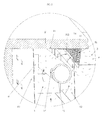
figure 3 représente une vue partielle en coupe transversale d'un meuble d'exposition ; - la
figure 4 représente une vue en coupe transversale d'un meuble d'exposition prise au niveau de l'humidificateur.
- the
figure 1 represents a perspective view of an exhibition furniture according to the invention; - the
figure 2 represents a detail view E of thefigure 1 ; - the
figure 3 represents a partial cross-sectional view of an exhibition stand; - the
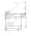
figure 4 represents a cross-sectional view of an exhibition stand taken at the humidifier.
Comme mentionné ci-dessus, l'invention a pour objet un meuble 1 d'exposition à froid ventilé pour la présentation de produits, en particulier de produits alimentaires. Ce meuble 1 comprend un humidificateur 2 d'air formé ici par un humidificateur à ultra-sons et une enceinte 3. Cette enceinte 3 comprend une zone 4 supérieure d'exposition des produits et une zone 5 inférieure technique contenant au moins partiellement des moyens 6 de circulation forcée de l'air et des moyens 7 de production de froid en vue d'un refroidissement dudit air.As mentioned above, the subject of the invention is a ventilated
Ces zones 4, 5 sont séparées l'une de l'autre par une pluralité de plateaux 8 de présentation des produits et communiquent entre elles par une chambre 9 disposée le long d'un des bords, appelé bord arrière 10 de la zone 4 supérieure d'exposition et par une ouverture 12 de reprise d'air disposée le long du bord opposé dit avant 11 de la zone 4 supérieure d'exposition. La chambre 9 est reliée en entrée 13, à la zone 5 inférieure technique, et en sortie 14, à la zone 4 supérieure d'exposition. L'air circule ainsi en boucle entre lesdites zones 4 et 5 avec un flux d'air aller circulant au-dessus du ou des plateaux 8 de présentation depuis la chambre 9 vers la ou les ouvertures 12 de reprise d'air et un flux d'air retour circulant au-dessous des plateaux 8 de présentation depuis la ou les ouvertures 12 de reprise d'air vers la chambre 9.These
Dans les exemples représentés, l'enceinte 3 est une enceinte ouverte côté face du dessus. La partie dite avant de l'enceinte destinée à faire face aux clients et jouxtant le bord 11 avant de la zone 4 supérieure d'exposition est pourvue d'une vitre 22 de protection, mais dépourvue d'un pare-haleine, qui viendrait fermer au moins partiellement la face du dessus de l'enceinte.In the examples shown, the
Bien évidemment, et de manière équivalente, cette enceinte aurait pu être complètement fermée.Of course, and equally, this speaker could have been completely closed.
La chambre 9 est quant à elle surmontée d'une tablette 21 sur laquelle les produits peuvent être posés avant d'être introduits dans l'enceinte et disposés sur le ou les plateaux d'exposition. Ce ou ces plateaux 8 d'exposition sont disposés de manière fixe ou amovible à l'intérieur de l'enceinte 3 et s'étendent à l'intérieur de l'enceinte 3 depuis une position sous la tablette 21 en direction de la partie avant de l'enceinte 3.The
Les moyens 6 de circulation forcée de l'air comprennent, quant à eux, des ventilateurs disposés le long d'une ligne sensiblement parallèle à l'un des bords avant 11 ou arrière 10 de la zone 4 supérieure d'exposition, à raison d'au moins trois ventilateurs par mètre linéaire.The
Dans l'exemple représenté, ces ventilateurs sont disposés dans la zone technique, de manière légèrement décalée par rapport à l'aplomb de la ou des ouvertures 12 de reprise d'air. En effet, la reprise d'air peut s'effectuer par une ouverture unique se présentant sous forme d'une lumière allongée s'étendant le long du bord avant 11 de la zone 4 supérieure d'exposition formée ici par l'un des bords du plateau ou par une pluralité de lumières comme illustré aux figures.In the example shown, these fans are arranged in the technical area, slightly offset from the plumb with the or
Les moyens 7 de production de froid sont formés par un évaporateur d'un circuit frigorifique. Cet évaporateur peut lui-même être réalisé sous forme d'un ou plusieurs échangeurs de chaleur, de préférence à plaques. Les plaques peuvent être des plaques disposées verticalement et reliées entre elles par un circuit de circulation de fluide frigorigène dit circuit de réfrigération. L'air est refroidi par circulation entre lesdites plaques avant d'être introduit dans la chambre 9 disposée le long du bord 10 arrière de la zone 4 supérieure d'exposition.The
Cette chambre 9 de type couloir comprend un fond 91, deux parois 92, 93, verticales, sensiblement parallèles, et s'étendant parallèlement au bord 10 arrière de la zone 4 supérieure d'exposition, et une face 94 du dessus.This
Les bords inférieur 921 et supérieur 922 de la paroi 92 verticale jouxtant la zone 4 supérieure d'exposition sont respectivement écartés du fond 91 et de la face 94 du dessus de la chambre 9 pour délimiter, entre le bord inférieur 921 et le fond 91, l'entrée 13 de la chambre 9 et entre le bord supérieur 922 et la face 94 du dessus, la sortie 14 de la chambre 9.The
De manière caractéristique à l'invention, la chambre 9 contient encore au moins un conduit 15 raccordable à l'humidificateur 2 d'air. Ce conduit 15 est un conduit diffuseur dont la paroi 16 périphérique de délimitation est munie d'ouvertures, appelées ouvertures 17 latérales, à travers lesquelles l'humidité, en l'occurrence le brouillard, produite par ledit humidificateur 2 est apte à être introduite dans ladite chambre 9.Characteristically to the invention, the
Ce conduit est ici un conduit cylindrique, de préférence en PVC, et les ouvertures sont des ouvertures circulaires de diamètre voisin de deux centimètres.This duct is here a cylindrical duct, preferably PVC, and the openings are circular openings with a diameter of about two centimeters.
Les ouvertures 17 latérales du conduit sont disposées le long du côté du conduit 15 opposé à celui faisant face à la zone 4 supérieure d'exposition et débouchent dans la chambre 9 en un emplacement situé au-dessus du plan passant par le ou les plateaux 8 de présentation.The
Le conduit 15 est quant à lui disposé sensiblement axialement et horizontalement à l'intérieur de la chambre 9, en s'étendant au-dessus du plan passant par la surface support formée par le ou les plateaux 8 de présentation. Ce conduit est ainsi porté de place en place par des supports 18 à l'intérieur de la chambre 9.The
Cette chambre 9 peut être réalisée sous forme d'une chambre non compartimentée ou au contraire, compartimentée pour former une pluralité de cellules disposées côte à côte le long du bord arrière 10 de la zone 4 supérieure d'exposition.This
La sortie 14 de la chambre 9 comprend une chicane 19. L'une des parois de cette chicane 19 est formée par une grille 20 perforée. Cette grille 20 perforée est disposée à l'extérieur de la chambre et s'étend verticalement depuis la tablette 21 en formant un écran sensiblement vertical devant l'ouverture formée par l'espace laissé libre entre le bord supérieur 922 de la paroi 92 verticale de la chambre jouxtant la zone 4 supérieure d'exposition et la face 94 du dessus de ladite chambre.The
Le fonctionnement d'un tel meuble réfrigéré est le suivant : l'humidificateur produit un brouillard diffusé dans la chambre 9 par l'intermédiaire du conduit 15. Ce brouillard est entraîné vers la sortie de la chambre par un flux d'air froid issu de la zone technique et produit à partir des ventilateurs qui entraînent ce flux d'air à travers les moyens 7 de production de froid avant entrée dans ladite chambre 9.The operation of such a refrigerated piece of furniture is as follows: the humidifier produces a fog diffused into the
L'air se charge en brouillard dans la chambre avant de circuler dans la zone d'exposition. L'air est ré aspiré par la ou les ouvertures de reprise d'air et entraîné par les ventilateurs pour un nouveau cycle de circulation en boucle.The air fogs in the room before moving into the exposure area. The air is sucked back into the air intake opening (s) and driven by the fans for a new loop circulation cycle.
Claims (10)
caractérisé en ce que ladite chambre (9) contient au moins un conduit (15) raccordable audit humidificateur (2) d'air, ce conduit (15) étant un conduit diffuseur dont la paroi (16) périphérique de délimitation est munie d'ouvertures appelées ouvertures (17) latérales à travers lesquelles l'humidité produite par ledit humidificateur (2) est apte à être introduite dans ladite chambre (9).Ventilated cold room furniture (1) for the presentation of products, such as food products, the cabinet (1) comprising an air humidifier (2) and at least one open or closed enclosure (3) comprising a zone (4) upper product exposure and a lower technical area (5) at least partially containing means (6) forced circulation of air and means (7) for producing cold for cooling said air, said zones (4, 5) being separated from each other at least by a plate (8) for presenting the products and communicating with each other at least by a chamber (9) arranged along one of the edges said rear (10) of the upper exposure zone (4) and by at least one air intake opening (12) disposed along the opposite said front edge (11) of said upper exposure zone (4) said chamber (9) being connected at the input (13) to the lower technical zone (5) and at the output (14) to the zone ( 4) upper exposure for circulating air loop between said zones (4, 5) with a flow of air flowing over the top or plates (8) of presentation from the chamber (9) to the or the air intake openings (12) and a return air flow circulating below the presentation tray (s) (8) from the air intake opening (s) to the chamber (9),
characterized in that said chamber (9) contains at least one duct (15) connectable to said air humidifier (2), said duct (15) being a diffuser duct whose peripheral delimiting wall (16) is provided with openings called lateral openings (17) through which the humidity produced by said humidifier (2) is adapted to be introduced into said chamber (9).
caractérisé en ce que les ouvertures (17) latérales du conduit (15) débouchent dans la chambre (9) en un emplacement situé au-dessus du plan passant par le ou les plateaux (8) de présentation.Furniture (1) according to claim 1,
characterized in that the lateral openings (17) of the duct (15) open into the chamber (9) at a location above the plane passing through the presentation tray (s) (8).
caractérisé en ce que les ouvertures (17) latérales du conduit (15) sont disposées le long du côté du conduit (15) opposé à celui faisant face à la zone (4) supérieure d'exposition.Furniture (1) according to one of the preceding claims,
characterized in that the lateral openings (17) of the duct (15) are arranged along the side of the duct (15) opposite to that facing the upper exposure zone (4).
caractérisé en ce que le conduit (15) est disposé dans ladite chambre (9) au moins partiellement au dessus du plan passant par le ou les plateaux (8) de présentation.Furniture (1) according to one of the preceding claims,
characterized in that the duct (15) is disposed in said chamber (9) at least partially above the plane passing through the or plateaux (8) of presentation.
caractérisé en ce que le conduit (15) est disposé sensiblement axialement à l'intérieur de ladite chambre (9), c'est-à-dire sensiblement parallèlement au bord arrière (10) de la zone (4) supérieure d'exposition.Furniture (1) according to one of the preceding claims,
characterized in that the duct (15) is arranged substantially axially inside said chamber (9), that is to say substantially parallel to the rear edge (10) of the upper exposure area (4).
caractérisé en ce que la sortie (14) de la chambre (9) comprend une chicane (19).Furniture (1) according to one of the preceding claims,
characterized in that the outlet (14) of the chamber (9) comprises a baffle (19).
caractérisé en ce que l'une des parois de la chicane (19) est formée par une grille (20) perforée.Furniture (1) according to claim 6,
characterized in that one of the walls of the baffle (19) is formed by a perforated grid (20).
caractérisé en ce que la chambre (9) est surmontée d'une tablette (21), en ce que la partie dite avant de l'enceinte (3) destinée à faire face au client et jouxtant le bord (11) avant de la zone (4) supérieure d'exposition est pourvue d'une vitre (22) de protection et en ce que le ou les plateaux (8) de présentation s'étendent à l'intérieur de l'enceinte (3) depuis une position sous la tablette (21) en direction de la partie avant de l'enceinte (3).Furniture (1) according to one of the preceding claims,
characterized in that the chamber (9) is surmounted by a shelf (21), in that the so-called front part of the enclosure (3) intended to face the customer and adjoining the edge (11) before the zone (4) upper exposure is provided with a protective glass (22) and in that the or presentation trays (8) extend inside the enclosure (3) from a position under the shelf (21) towards the front part of the enclosure (3).
caractérisé en ce que la chambre (9) de type couloir comprend un fond (91),
deux parois (92, 93) verticales sensiblement parallèles et s'étendant parallèlement au bord (10) arrière de la zone (4) supérieure d'exposition et une face (94) du dessus, les bords inférieur (921) et supérieur (922) de la paroi (92) verticale jouxtant la zone (4) supérieure d'exposition étant respectivement écartés du fond (91) et de la face (94) du dessus de la chambre (9) pour délimiter, entre bord inférieur (921) et fond (91), l'entrée (13) de la chambre (9) et, entre bord supérieur (922) et face (94) du dessus, la sortie (14) de la chambre (9).Furniture (1) according to one of the preceding claims,
characterized in that the corridor-type chamber (9) comprises a bottom (91),
two substantially parallel vertical walls (92, 93) extending parallel to the rear edge (10) of the upper exposure area (4) and a top face (94), the lower (921) and upper (922) edges; ) of the vertical wall (92) adjoining the upper exposure zone (4) being respectively spaced from the bottom (91) and the face (94) of the top of the chamber (9) to delimit, between the lower edge (921) and bottom (91), the inlet (13) of the chamber (9) and, between the upper edge (922) and the face (94) of the top, the outlet (14) of the chamber (9).
caractérisé en ce que les moyens (6) de circulation forcée de l'air comprennent des ventilateurs disposés le long d'une ligne sensiblement parallèle à l'un des bords avant (11) ou arrière (10) de la zone (4) supérieure d'exposition à raison d'au moins trois ventilateurs par mètre linéaire.Furniture (1) according to one of the preceding claims,
characterized in that the forced air circulation means (6) comprise fans arranged along a line substantially parallel to one of the front (11) or rear (10) edges of the upper zone (4) at least three fans per linear meter.
Applications Claiming Priority (1)
| Application Number | Priority Date | Filing Date | Title |
|---|---|---|---|
| FR1360221A FR3012027B1 (en) | 2013-10-21 | 2013-10-21 | VENTILATED COLD EXPOSURE CABINET |
Publications (2)
| Publication Number | Publication Date |
|---|---|
| EP2862484A1 true EP2862484A1 (en) | 2015-04-22 |
| EP2862484B1 EP2862484B1 (en) | 2016-03-23 |
Family
ID=49713347
Family Applications (1)
| Application Number | Title | Priority Date | Filing Date |
|---|---|---|---|
| EP14187447.9A Not-in-force EP2862484B1 (en) | 2013-10-21 | 2014-10-02 | Ventilated cold display unit |
Country Status (3)
| Country | Link |
|---|---|
| EP (1) | EP2862484B1 (en) |
| ES (1) | ES2578128T3 (en) |
| FR (1) | FR3012027B1 (en) |
Families Citing this family (1)
| Publication number | Priority date | Publication date | Assignee | Title |
|---|---|---|---|---|
| DE102020103571A1 (en) | 2020-02-12 | 2021-08-12 | Ake Ausseer Kälte- Und Edelstahltechnik Gmbh | Goods presenter |
Citations (2)
| Publication number | Priority date | Publication date | Assignee | Title |
|---|---|---|---|---|
| DE3313399A1 (en) * | 1983-04-13 | 1984-10-18 | Karl 8904 Friedberg Leuprecht | Refrigerated cabinet |
| GB2301175A (en) * | 1995-05-26 | 1996-11-27 | Pendred Norman Co | Display cabinet |
-
2013
- 2013-10-21 FR FR1360221A patent/FR3012027B1/en not_active Expired - Fee Related
-
2014
- 2014-10-02 ES ES14187447.9T patent/ES2578128T3/en active Active
- 2014-10-02 EP EP14187447.9A patent/EP2862484B1/en not_active Not-in-force
Patent Citations (2)
| Publication number | Priority date | Publication date | Assignee | Title |
|---|---|---|---|---|
| DE3313399A1 (en) * | 1983-04-13 | 1984-10-18 | Karl 8904 Friedberg Leuprecht | Refrigerated cabinet |
| GB2301175A (en) * | 1995-05-26 | 1996-11-27 | Pendred Norman Co | Display cabinet |
Also Published As
| Publication number | Publication date |
|---|---|
| FR3012027B1 (en) | 2016-02-19 |
| FR3012027A1 (en) | 2015-04-24 |
| ES2578128T3 (en) | 2016-07-20 |
| EP2862484B1 (en) | 2016-03-23 |
Similar Documents
| Publication | Publication Date | Title |
|---|---|---|
| CA2881040C (en) | Facility for refreshing items displayed for sale with a mist of water droplets | |
| US9877502B2 (en) | Food dehydrator | |
| PT2994023T (en) | Improvements in or relating to refrigerated display appliances | |
| US20180066884A1 (en) | Cold Plate Shelf Assembly for a Refrigerator | |
| EP2862484B1 (en) | Ventilated cold display unit | |
| EP1741999B1 (en) | Refrigerated display case with a lower chest and an upper cupboard | |
| FR3071709B1 (en) | VENTILATED COLD EXPOSURE CABINET | |
| US2247736A (en) | Refrigerator | |
| JP6679826B2 (en) | Showcase | |
| US11096504B2 (en) | Merchandiser | |
| EP3348174B1 (en) | Ventilated cold display unit | |
| FR2988278A1 (en) | Cold ventilated furniture piece for presentation of e.g. foodstuff, in store, has blowing openings and air resumption unit utilized for air circulation placed in presentation plate, where openings and resumption unit form holding unit | |
| JP5673001B2 (en) | Showcase | |
| FR3046532A1 (en) | VENTILATED COLD EXPOSURE CABINET FOR PRESENTATION OF PRODUCTS AND PRODUCT DISPLAY PANEL FOR SUCH A FURNITURE | |
| FR3125114A1 (en) | Open vertical refrigerated display case comprising improved nebulization means | |
| WO2023281376A1 (en) | Open vertical refrigerated display case comprising improved nebulizing means | |
| FR2525886A1 (en) | Refrigerated display case for food products - uses glass enclosure and has compressor in base and evaporator in ceiling with condensation trap beneath it | |
| FR3063422A3 (en) | CLOSED VERTICAL VENTILATED REFRIGERATED FURNITURE FURNITURE | |
| FR2732872A1 (en) | Autonomous movable refrigerated food display counter | |
| EP3220780A1 (en) | Facility for refreshing products in the presence of a layer of ice | |
| JP2015150041A (en) | open showcase | |
| FR3023360B1 (en) | COOLING SYSTEM OF A LOCAL BY A COLD AIR FLOW PULSE UNDER THE CEILING. | |
| EP3366165A1 (en) | Hybrid refrigerated butcher's block with two modes of operation | |
| EP0580494A1 (en) | Display case with refrigerated shelf | |
| JP2004294031A (en) | Showcase |
Legal Events
| Date | Code | Title | Description |
|---|---|---|---|
| PUAI | Public reference made under article 153(3) epc to a published international application that has entered the european phase |
Free format text: ORIGINAL CODE: 0009012 |
|
| 17P | Request for examination filed |
Effective date: 20141002 |
|
| AK | Designated contracting states |
Kind code of ref document: A1 Designated state(s): AL AT BE BG CH CY CZ DE DK EE ES FI FR GB GR HR HU IE IS IT LI LT LU LV MC MK MT NL NO PL PT RO RS SE SI SK SM TR |
|
| AX | Request for extension of the european patent |
Extension state: BA ME |
|
| R17P | Request for examination filed (corrected) |
Effective date: 20150708 |
|
| RBV | Designated contracting states (corrected) |
Designated state(s): AL AT BE BG CH CY CZ DE DK EE ES FI FR GB GR HR HU IE IS IT LI LT LU LV MC MK MT NL NO PL PT RO RS SE SI SK SM TR |
|
| GRAP | Despatch of communication of intention to grant a patent |
Free format text: ORIGINAL CODE: EPIDOSNIGR1 |
|
| RIC1 | Information provided on ipc code assigned before grant |
Ipc: A47F 3/04 20060101AFI20151119BHEP |
|
| INTG | Intention to grant announced |
Effective date: 20151204 |
|
| GRAS | Grant fee paid |
Free format text: ORIGINAL CODE: EPIDOSNIGR3 |
|
| GRAA | (expected) grant |
Free format text: ORIGINAL CODE: 0009210 |
|
| AK | Designated contracting states |
Kind code of ref document: B1 Designated state(s): AL AT BE BG CH CY CZ DE DK EE ES FI FR GB GR HR HU IE IS IT LI LT LU LV MC MK MT NL NO PL PT RO RS SE SI SK SM TR |
|
| REG | Reference to a national code |
Ref country code: GB Ref legal event code: FG4D Free format text: NOT ENGLISH |
|
| REG | Reference to a national code |
Ref country code: CH Ref legal event code: EP |
|
| REG | Reference to a national code |
Ref country code: AT Ref legal event code: REF Ref document number: 782257 Country of ref document: AT Kind code of ref document: T Effective date: 20160415 |
|
| REG | Reference to a national code |
Ref country code: IE Ref legal event code: FG4D Free format text: LANGUAGE OF EP DOCUMENT: FRENCH |
|
| REG | Reference to a national code |
Ref country code: DE Ref legal event code: R096 Ref document number: 602014001199 Country of ref document: DE |
|
| REG | Reference to a national code |
Ref country code: ES Ref legal event code: FG2A Ref document number: 2578128 Country of ref document: ES Kind code of ref document: T3 Effective date: 20160720 |
|
| REG | Reference to a national code |
Ref country code: LT Ref legal event code: MG4D |
|
| REG | Reference to a national code |
Ref country code: NL Ref legal event code: MP Effective date: 20160323 |
|
| PG25 | Lapsed in a contracting state [announced via postgrant information from national office to epo] |
Ref country code: NO Free format text: LAPSE BECAUSE OF FAILURE TO SUBMIT A TRANSLATION OF THE DESCRIPTION OR TO PAY THE FEE WITHIN THE PRESCRIBED TIME-LIMIT Effective date: 20160623 Ref country code: HR Free format text: LAPSE BECAUSE OF FAILURE TO SUBMIT A TRANSLATION OF THE DESCRIPTION OR TO PAY THE FEE WITHIN THE PRESCRIBED TIME-LIMIT Effective date: 20160323 Ref country code: GR Free format text: LAPSE BECAUSE OF FAILURE TO SUBMIT A TRANSLATION OF THE DESCRIPTION OR TO PAY THE FEE WITHIN THE PRESCRIBED TIME-LIMIT Effective date: 20160624 Ref country code: FI Free format text: LAPSE BECAUSE OF FAILURE TO SUBMIT A TRANSLATION OF THE DESCRIPTION OR TO PAY THE FEE WITHIN THE PRESCRIBED TIME-LIMIT Effective date: 20160323 |
|
| REG | Reference to a national code |
Ref country code: AT Ref legal event code: MK05 Ref document number: 782257 Country of ref document: AT Kind code of ref document: T Effective date: 20160323 |
|
| PG25 | Lapsed in a contracting state [announced via postgrant information from national office to epo] |
Ref country code: NL Free format text: LAPSE BECAUSE OF FAILURE TO SUBMIT A TRANSLATION OF THE DESCRIPTION OR TO PAY THE FEE WITHIN THE PRESCRIBED TIME-LIMIT Effective date: 20160323 Ref country code: SE Free format text: LAPSE BECAUSE OF FAILURE TO SUBMIT A TRANSLATION OF THE DESCRIPTION OR TO PAY THE FEE WITHIN THE PRESCRIBED TIME-LIMIT Effective date: 20160323 Ref country code: RS Free format text: LAPSE BECAUSE OF FAILURE TO SUBMIT A TRANSLATION OF THE DESCRIPTION OR TO PAY THE FEE WITHIN THE PRESCRIBED TIME-LIMIT Effective date: 20160323 Ref country code: LV Free format text: LAPSE BECAUSE OF FAILURE TO SUBMIT A TRANSLATION OF THE DESCRIPTION OR TO PAY THE FEE WITHIN THE PRESCRIBED TIME-LIMIT Effective date: 20160323 Ref country code: LT Free format text: LAPSE BECAUSE OF FAILURE TO SUBMIT A TRANSLATION OF THE DESCRIPTION OR TO PAY THE FEE WITHIN THE PRESCRIBED TIME-LIMIT Effective date: 20160323 |
|
| REG | Reference to a national code |
Ref country code: FR Ref legal event code: PLFP Year of fee payment: 3 |
|
| PG25 | Lapsed in a contracting state [announced via postgrant information from national office to epo] |
Ref country code: IS Free format text: LAPSE BECAUSE OF FAILURE TO SUBMIT A TRANSLATION OF THE DESCRIPTION OR TO PAY THE FEE WITHIN THE PRESCRIBED TIME-LIMIT Effective date: 20160723 Ref country code: PL Free format text: LAPSE BECAUSE OF FAILURE TO SUBMIT A TRANSLATION OF THE DESCRIPTION OR TO PAY THE FEE WITHIN THE PRESCRIBED TIME-LIMIT Effective date: 20160323 Ref country code: EE Free format text: LAPSE BECAUSE OF FAILURE TO SUBMIT A TRANSLATION OF THE DESCRIPTION OR TO PAY THE FEE WITHIN THE PRESCRIBED TIME-LIMIT Effective date: 20160323 |
|
| PG25 | Lapsed in a contracting state [announced via postgrant information from national office to epo] |
Ref country code: CZ Free format text: LAPSE BECAUSE OF FAILURE TO SUBMIT A TRANSLATION OF THE DESCRIPTION OR TO PAY THE FEE WITHIN THE PRESCRIBED TIME-LIMIT Effective date: 20160323 Ref country code: SM Free format text: LAPSE BECAUSE OF FAILURE TO SUBMIT A TRANSLATION OF THE DESCRIPTION OR TO PAY THE FEE WITHIN THE PRESCRIBED TIME-LIMIT Effective date: 20160323 Ref country code: AT Free format text: LAPSE BECAUSE OF FAILURE TO SUBMIT A TRANSLATION OF THE DESCRIPTION OR TO PAY THE FEE WITHIN THE PRESCRIBED TIME-LIMIT Effective date: 20160323 Ref country code: SK Free format text: LAPSE BECAUSE OF FAILURE TO SUBMIT A TRANSLATION OF THE DESCRIPTION OR TO PAY THE FEE WITHIN THE PRESCRIBED TIME-LIMIT Effective date: 20160323 Ref country code: PT Free format text: LAPSE BECAUSE OF FAILURE TO SUBMIT A TRANSLATION OF THE DESCRIPTION OR TO PAY THE FEE WITHIN THE PRESCRIBED TIME-LIMIT Effective date: 20160725 Ref country code: RO Free format text: LAPSE BECAUSE OF FAILURE TO SUBMIT A TRANSLATION OF THE DESCRIPTION OR TO PAY THE FEE WITHIN THE PRESCRIBED TIME-LIMIT Effective date: 20160323 |
|
| PG25 | Lapsed in a contracting state [announced via postgrant information from national office to epo] |
Ref country code: IT Free format text: LAPSE BECAUSE OF FAILURE TO SUBMIT A TRANSLATION OF THE DESCRIPTION OR TO PAY THE FEE WITHIN THE PRESCRIBED TIME-LIMIT Effective date: 20160323 |
|
| REG | Reference to a national code |
Ref country code: DE Ref legal event code: R097 Ref document number: 602014001199 Country of ref document: DE |
|
| PLBE | No opposition filed within time limit |
Free format text: ORIGINAL CODE: 0009261 |
|
| STAA | Information on the status of an ep patent application or granted ep patent |
Free format text: STATUS: NO OPPOSITION FILED WITHIN TIME LIMIT |
|
| PG25 | Lapsed in a contracting state [announced via postgrant information from national office to epo] |
Ref country code: DK Free format text: LAPSE BECAUSE OF FAILURE TO SUBMIT A TRANSLATION OF THE DESCRIPTION OR TO PAY THE FEE WITHIN THE PRESCRIBED TIME-LIMIT Effective date: 20160323 |
|
| PG25 | Lapsed in a contracting state [announced via postgrant information from national office to epo] |
Ref country code: BG Free format text: LAPSE BECAUSE OF FAILURE TO SUBMIT A TRANSLATION OF THE DESCRIPTION OR TO PAY THE FEE WITHIN THE PRESCRIBED TIME-LIMIT Effective date: 20160623 |
|
| 26N | No opposition filed |
Effective date: 20170102 |
|
| REG | Reference to a national code |
Ref country code: DE Ref legal event code: R119 Ref document number: 602014001199 Country of ref document: DE |
|
| PG25 | Lapsed in a contracting state [announced via postgrant information from national office to epo] |
Ref country code: SI Free format text: LAPSE BECAUSE OF FAILURE TO SUBMIT A TRANSLATION OF THE DESCRIPTION OR TO PAY THE FEE WITHIN THE PRESCRIBED TIME-LIMIT Effective date: 20160323 |
|
| REG | Reference to a national code |
Ref country code: IE Ref legal event code: MM4A |
|
| PG25 | Lapsed in a contracting state [announced via postgrant information from national office to epo] |
Ref country code: DE Free format text: LAPSE BECAUSE OF NON-PAYMENT OF DUE FEES Effective date: 20170503 |
|
| REG | Reference to a national code |
Ref country code: FR Ref legal event code: PLFP Year of fee payment: 4 |
|
| PG25 | Lapsed in a contracting state [announced via postgrant information from national office to epo] |
Ref country code: IE Free format text: LAPSE BECAUSE OF NON-PAYMENT OF DUE FEES Effective date: 20161002 |
|
| PGFP | Annual fee paid to national office [announced via postgrant information from national office to epo] |
Ref country code: LU Payment date: 20171019 Year of fee payment: 4 |
|
| PGFP | Annual fee paid to national office [announced via postgrant information from national office to epo] |
Ref country code: BE Payment date: 20171019 Year of fee payment: 4 |
|
| PG25 | Lapsed in a contracting state [announced via postgrant information from national office to epo] |
Ref country code: ES Free format text: LAPSE BECAUSE OF NON-PAYMENT OF DUE FEES Effective date: 20171003 Ref country code: HU Free format text: LAPSE BECAUSE OF FAILURE TO SUBMIT A TRANSLATION OF THE DESCRIPTION OR TO PAY THE FEE WITHIN THE PRESCRIBED TIME-LIMIT; INVALID AB INITIO Effective date: 20141002 |
|
| REG | Reference to a national code |
Ref country code: ES Ref legal event code: FD2A Effective date: 20180620 |
|
| PG25 | Lapsed in a contracting state [announced via postgrant information from national office to epo] |
Ref country code: MK Free format text: LAPSE BECAUSE OF FAILURE TO SUBMIT A TRANSLATION OF THE DESCRIPTION OR TO PAY THE FEE WITHIN THE PRESCRIBED TIME-LIMIT Effective date: 20160323 Ref country code: MC Free format text: LAPSE BECAUSE OF FAILURE TO SUBMIT A TRANSLATION OF THE DESCRIPTION OR TO PAY THE FEE WITHIN THE PRESCRIBED TIME-LIMIT Effective date: 20160323 Ref country code: MT Free format text: LAPSE BECAUSE OF FAILURE TO SUBMIT A TRANSLATION OF THE DESCRIPTION OR TO PAY THE FEE WITHIN THE PRESCRIBED TIME-LIMIT Effective date: 20160323 Ref country code: CY Free format text: LAPSE BECAUSE OF FAILURE TO SUBMIT A TRANSLATION OF THE DESCRIPTION OR TO PAY THE FEE WITHIN THE PRESCRIBED TIME-LIMIT Effective date: 20160323 |
|
| PG25 | Lapsed in a contracting state [announced via postgrant information from national office to epo] |
Ref country code: ES Free format text: LAPSE BECAUSE OF NON-PAYMENT OF DUE FEES Effective date: 20161003 |
|
| REG | Reference to a national code |
Ref country code: FR Ref legal event code: PLFP Year of fee payment: 5 |
|
| PG25 | Lapsed in a contracting state [announced via postgrant information from national office to epo] |
Ref country code: AL Free format text: LAPSE BECAUSE OF FAILURE TO SUBMIT A TRANSLATION OF THE DESCRIPTION OR TO PAY THE FEE WITHIN THE PRESCRIBED TIME-LIMIT Effective date: 20160323 Ref country code: TR Free format text: LAPSE BECAUSE OF FAILURE TO SUBMIT A TRANSLATION OF THE DESCRIPTION OR TO PAY THE FEE WITHIN THE PRESCRIBED TIME-LIMIT Effective date: 20160323 |
|
| PGFP | Annual fee paid to national office [announced via postgrant information from national office to epo] |
Ref country code: CH Payment date: 20181204 Year of fee payment: 10 Ref country code: GB Payment date: 20181019 Year of fee payment: 5 |
|
| REG | Reference to a national code |
Ref country code: BE Ref legal event code: MM Effective date: 20181031 |
|
| PG25 | Lapsed in a contracting state [announced via postgrant information from national office to epo] |
Ref country code: LU Free format text: LAPSE BECAUSE OF NON-PAYMENT OF DUE FEES Effective date: 20181002 |
|
| PG25 | Lapsed in a contracting state [announced via postgrant information from national office to epo] |
Ref country code: BE Free format text: LAPSE BECAUSE OF NON-PAYMENT OF DUE FEES Effective date: 20181031 |
|
| REG | Reference to a national code |
Ref country code: CH Ref legal event code: PL |
|
| PG25 | Lapsed in a contracting state [announced via postgrant information from national office to epo] |
Ref country code: CH Free format text: LAPSE BECAUSE OF NON-PAYMENT OF DUE FEES Effective date: 20191031 Ref country code: LI Free format text: LAPSE BECAUSE OF NON-PAYMENT OF DUE FEES Effective date: 20191031 |
|
| GBPC | Gb: european patent ceased through non-payment of renewal fee |
Effective date: 20191002 |
|
| PG25 | Lapsed in a contracting state [announced via postgrant information from national office to epo] |
Ref country code: GB Free format text: LAPSE BECAUSE OF NON-PAYMENT OF DUE FEES Effective date: 20191002 |
|
| PGFP | Annual fee paid to national office [announced via postgrant information from national office to epo] |
Ref country code: FR Payment date: 20211022 Year of fee payment: 8 |
|
| PG25 | Lapsed in a contracting state [announced via postgrant information from national office to epo] |
Ref country code: FR Free format text: LAPSE BECAUSE OF NON-PAYMENT OF DUE FEES Effective date: 20221031 |