EP2861483B1 - Bodywork structure of a motor vehicle - Google Patents
Bodywork structure of a motor vehicle Download PDFInfo
- Publication number
- EP2861483B1 EP2861483B1 EP13733374.6A EP13733374A EP2861483B1 EP 2861483 B1 EP2861483 B1 EP 2861483B1 EP 13733374 A EP13733374 A EP 13733374A EP 2861483 B1 EP2861483 B1 EP 2861483B1
- Authority
- EP
- European Patent Office
- Prior art keywords
- shock absorber
- vehicle
- front shock
- scuttle
- reinforcing element
- Prior art date
- Legal status (The legal status is an assumption and is not a legal conclusion. Google has not performed a legal analysis and makes no representation as to the accuracy of the status listed.)
- Active
Links
- 239000006096 absorbing agent Substances 0.000 claims description 31
- 230000035939 shock Effects 0.000 claims description 31
- 230000003014 reinforcing effect Effects 0.000 claims description 25
- 230000002787 reinforcement Effects 0.000 claims description 14
- 238000010438 heat treatment Methods 0.000 description 35
- 238000005192 partition Methods 0.000 description 31
- 101100441413 Caenorhabditis elegans cup-15 gene Proteins 0.000 description 9
- 238000005086 pumping Methods 0.000 description 3
- 208000031968 Cadaver Diseases 0.000 description 1
- 229910000831 Steel Inorganic materials 0.000 description 1
- 230000015556 catabolic process Effects 0.000 description 1
- 238000006731 degradation reaction Methods 0.000 description 1
- 238000005096 rolling process Methods 0.000 description 1
- 230000003068 static effect Effects 0.000 description 1
- 239000010959 steel Substances 0.000 description 1
- 238000003466 welding Methods 0.000 description 1
Images
Classifications
-
- B—PERFORMING OPERATIONS; TRANSPORTING
- B62—LAND VEHICLES FOR TRAVELLING OTHERWISE THAN ON RAILS
- B62D—MOTOR VEHICLES; TRAILERS
- B62D25/00—Superstructure or monocoque structure sub-units; Parts or details thereof not otherwise provided for
- B62D25/08—Front or rear portions
- B62D25/082—Engine compartments
-
- B—PERFORMING OPERATIONS; TRANSPORTING
- B62—LAND VEHICLES FOR TRAVELLING OTHERWISE THAN ON RAILS
- B62D—MOTOR VEHICLES; TRAILERS
- B62D25/00—Superstructure or monocoque structure sub-units; Parts or details thereof not otherwise provided for
- B62D25/08—Front or rear portions
- B62D25/088—Details of structures as upper supports for springs or dampers
Definitions
- the invention relates to a body structure of a motor vehicle and, more particularly, to a front upper structure of a motor vehicle body arranged in front of a passenger compartment cell of the vehicle, of the type comprising a transverse heating partition delimiting a body hollow and having a boss on the side of a side wall of said support structure for a wing of the vehicle and on an inner side of which is mounted integrally, immediately in front of said transverse heating partition, a front damper cup, which is carried by a front shock absorber riser adjoining said inner face, said front shock absorber cup being bonded to a heating partition reinforcement, which extends substantially in the longitudinal alignment of the hollow body delimited by said heating partition.
- a transverse heating partition delimiting a body hollow and having a boss on the side of a side wall of said support structure for a wing of the vehicle and on an inner side of which is mounted integrally, immediately in front of said transverse heating partition, a front damper cup, which is carried by a front shock absorber riser adjoining said inner face
- a commonly pursued objective relates to increasing the frequency of the eigen mode of dynamic torsion of the vehicle. Indeed, this mode participates directly in the dynamic behavior of the vehicle and, in particular, is directly related to the acoustic comfort of the vehicle.
- an important acoustic parameter generally required by the specifications concerns acoustic inertness, making it possible to measure the stiffness of a source emitting sound waves, which is expressed in N / m.
- the specification requires a minimum value for the inertance of the front shock absorber cups, in the Y direction, ie in the direction perpendicular to the longitudinal direction of the vehicle.
- This value can for example be set at 2.10 7 N / m.
- the heating partition is displaced in translation along the vertical axis Z of the vehicle, a phenomenon commonly known as "pumping", which is further accentuated by the presence of the boss made on one side the heating partition and intended to adapt the latter to the presence near the brake servo device (mastervac).
- This phenomenon causes training in rotation of the front damper cup arranged in the vicinity of the boss of the heating partition, which cup is deformed by pivoting on itself.
- the rotation of this front damper cup causes a significant degradation of its inertance in the Y direction, resulting in a significant noise nuisance.
- the presence of the heating partition reinforcement is then essential to reinforce the stiffness of the connection between the front damper cup and the heating partition, but is however insufficient to be able to significantly increase the inertness of the cup.
- the purpose of the present invention is to propose a front upper structure of a motor vehicle body capable of overcoming these disadvantages.
- the upper front structure of a motor vehicle body of the invention is essentially characterized in that it comprises a reinforcing element arranged between said front damper cup raiser and said heating wall reinforcement, for preventing rotational deformation movements of said front damper cup during translational motion along a vertical axis of the vehicle of said transverse heating partition.
- the stiffness of the front damper cup connection and the heating wall is significantly increased, allowing the inertness of the front damper cup located in the vicinity of the boss of the heating partition to at least to bring the price significantly closer to, or even to reach, the value fixed by the specifications.
- the torsional stiffness of the body is thus improved, which promotes an increase in the frequency of the own mode of dynamic torsion of the vehicle.
- this gain in stiffness of the body structure is advantageously provided by limiting the mass input.
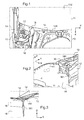
- the figure 1 schematically represents a vehicle seen from above, in the plane (X, Y), the longitudinal direction of the vehicle being along X.
- the right part of the front upper body structure 10, which relates more particularly to the present invention, is shown.
- This structure upper front body 10 is arranged in front of a rigid cell 11, forming a passenger compartment of the motor vehicle, closed by a windshield 110.
- the front upper structure 10 comprises a transverse heating partition 12 substantially vertical, which is interposed between the upper front body structure 10 and the cell 11, for delimiting a hollow body for a vehicle heating equipment.
- a boss 121 is made by stamping the transverse heating partition 12, to adapt the heating partition to the presence of the brake servo device (mastervac) nearby.
- This boss 121 of the transverse heating partition 12 is arranged in the vicinity of a vertical side wall 14, delimiting the front upper body structure 10 and intended to form a support for the right front fender of the vehicle.
- the upper front body structure 10 also comprises, in front of and in the immediate vicinity of the heating partition 12, a front shock absorber cup 15, called the right front shock absorber cup, mounted integral with the side wall 14 and which is worn by a front shock absorber cup raiser 16, said right front shock absorber cup raiser, adjacent to the inner face of the side wall 14.
- the right front shock absorber cup 15 is further bonded to a bulkhead reinforcement heating 13, which extends substantially in the longitudinal alignment of the hollow body defined by the heating partition 12, between the heating partition 12 and the right front shock absorber cup 15.
- figure 1 illustrates the rotational deformation movement undergone by the right front shock absorber cup 15 in the plane (X, Y) during "pumping" of the heating partition 12, whose boss 121 accentuates the intensity.
- This rotation of the right front shock absorber cup 15 causes, as explained in the preamble, a too low inertness of the right front shock absorber cup 15 in the Y direction.
- the upper body before structure comprises a reinforcing element 18, arranged between the right front shock absorber cup raiser 16 and the heating partition reinforcement 13, so as to prevent the movements of deformation in rotation of the cup of right front shock absorber 15 during "pumping" of the transverse heating partition 12, while the vehicle is traveling.
- This reinforcing element 18 advantageously participates in the the stiffness necessary to increase the frequency of the torsional mode of torsion of the body, by making it possible to reinforce the stiffness of the connection between the right front shock absorber cup 15 and the heating partition 12, thanks to the specific action and very localized it realizes of joining the front shock absorber riser 16 and the heating partition reinforcement 13.
- the reinforcing member 18 is shown apparent for clarity on the view of the figure 2 , the detail view in section of the figure 3 shows that the reinforcing member 18 is arranged between the right front shock absorber riser 16 and the heating partition reinforcement 13, at the upper end of the side face of the front shock absorber riser 16 located at the right of the hollow body delimited by the heating partition 12 and the heating partition reinforcement 13.
- the reinforcing element 18 has the shape of a profile, preferably made of steel, which has a substantially square cross section oriented along the (Z, Y) plane, ie in the plane perpendicular to the longitudinal direction. X of the vehicle.
- the profile has a first flange 181 welded to the right front shock absorber riser 16, while a second flange 182, substantially perpendicular to the first flange 181, is welded to the heating wall reinforcement 13.
- the first flange 181 of the reinforcing element 18 is welded by five points of welding to the right front shock absorber cup raiser 16 and the second flange 182 of the reinforcing element 18 is welded by three spot welds to the heating partition reinforcement 13.
- the reinforcing element 18 has a first dimension oriented substantially in the longitudinal direction X of the vehicle.
- the length of this first dimension is at least equal to 100 millimeters.
- the reinforcing element 18 also comprises a second dimension oriented substantially along the vertical axis Z of the vehicle.
- the length of this second dimension is at least equal to 100 millimeters.
- the reinforcing element 18 finally comprises a third dimension along the Y axis of the vehicle, which defines the overlap length between the second flange 182 of the reinforcing element 18 and the heating partition reinforcement 13.
- the length third dimension is at less than 25 millimeters.
- the reinforcing element 18 advantageously has a thickness substantially equal to 1.5 millimeters.
- This configuration of the reinforcing element 18 makes it possible to significantly increase the acoustic inertness of the right front shock absorber cup 15, by increasing the stiffness of the connection between the front shock absorber cup 15 and the heating partition 12.
Description
L'invention concerne une structure de caisse d'un véhicule automobile et, plus particulièrement, une structure supérieure avant de caisse de véhicule automobile agencée en avant d'une cellule formant habitacle du véhicule, du type comportant une cloison de chauffage transversale délimitant un corps creux et présentant un bossage du côté d'une paroi latérale de ladite structure formant support pour une aile du véhicule et sur une face intérieure de laquelle est montée solidaire, immédiatement en avant de ladite cloison de chauffage transversale, une coupelle d'amortisseur avant, qui est portée par une rehausse de coupelle d'amortisseur avant adjacente à ladite face intérieure, ladite coupelle d'amortisseur avant étant liée à un renfort de cloison de chauffage, qui s'étend sensiblement dans l'alignement longitudinal du corps creux délimité par ladite cloison de chauffage. Le document
On cherche généralement à rendre les différentes parties de la structure de caisse résistantes vis-à-vis des contraintes statiques et dynamiques auxquelles le véhicule est exposé. Dans ce contexte, un objectif communément poursuivi concerne l'augmentation de la fréquence du mode propre de torsion dynamique du véhicule. En effet, ce mode participe directement au comportement dynamique du véhicule et, en particulier, est directement lié au confort acoustique du véhicule. A cet égard, un paramètre acoustique important généralement requis par le cahier des charges concerne l'inertance acoustique, permettant de mesurer la raideur d'une source émettrice d'ondes sonores, qui s'exprime en N/m. En particulier, le cahier des charges exige une valeur minimale pour l'inertance des coupelles d'amortisseur avant, dans la direction Y, i.e. dans la direction perpendiculaire à la direction longitudinale du véhicule. Cette valeur peut par exemple être fixée à 2.107 N/m.It is generally sought to make the different parts of the body structure resistant to the static and dynamic stresses to which the vehicle is exposed. In this context, a commonly pursued objective relates to increasing the frequency of the eigen mode of dynamic torsion of the vehicle. Indeed, this mode participates directly in the dynamic behavior of the vehicle and, in particular, is directly related to the acoustic comfort of the vehicle. In this respect, an important acoustic parameter generally required by the specifications concerns acoustic inertness, making it possible to measure the stiffness of a source emitting sound waves, which is expressed in N / m. In particular, the specification requires a minimum value for the inertance of the front shock absorber cups, in the Y direction, ie in the direction perpendicular to the longitudinal direction of the vehicle. This value can for example be set at 2.10 7 N / m.
Or, lorsque le véhicule est en phase de roulement, la cloison de chauffage subit des déplacements en translation suivant l'axe vertical Z du véhicule, phénomène communément appelé « pompage », qui se trouve encore accentué par la présence du bossage réalisé sur un côté de la cloison de chauffage et destiné à adapter cette dernière à la présence à proximité du dispositif de servofrein (mastervac). Ce phénomène provoque l'entraînement en rotation de la coupelle d'amortisseur avant agencée au voisinage de ce bossage de la cloison de chauffage, laquelle coupelle se déforme en pivotant sur elle-même. La rotation de cette coupelle d'amortisseur avant engendre une dégradation significative de son inertance dans la direction Y, entraînant une nuisance acoustique importante. La présence du renfort de cloison de chauffage est alors essentielle pour renforcer la raideur de la liaison entre cette coupelle d'amortisseur avant et la cloison de chauffage, mais est toutefois insuffisante pour pouvoir élever notablement l'inertance de la coupelle.However, when the vehicle is in rolling phase, the heating partition is displaced in translation along the vertical axis Z of the vehicle, a phenomenon commonly known as "pumping", which is further accentuated by the presence of the boss made on one side the heating partition and intended to adapt the latter to the presence near the brake servo device (mastervac). This phenomenon causes training in rotation of the front damper cup arranged in the vicinity of the boss of the heating partition, which cup is deformed by pivoting on itself. The rotation of this front damper cup causes a significant degradation of its inertance in the Y direction, resulting in a significant noise nuisance. The presence of the heating partition reinforcement is then essential to reinforce the stiffness of the connection between the front damper cup and the heating partition, but is however insufficient to be able to significantly increase the inertness of the cup.
Dans ce contexte la présente invention a pour but de proposer une structure supérieure avant de caisse de véhicule automobile susceptible de remédier à ces inconvénients.In this context, the purpose of the present invention is to propose a front upper structure of a motor vehicle body capable of overcoming these disadvantages.
A cette fin, la structure supérieure avant de caisse de véhicule automobile de l'invention, par ailleurs conforme à la définition générique qu'en donne le préambule ci-dessus, est essentiellement caractérisée en ce qu'elle comporte un élément de renfort agencé entre ladite rehausse de coupelle d'amortisseur avant et ledit renfort de cloison de chauffage, pour prévenir les mouvements de déformation en rotation de ladite coupelle d'amortisseur avant lors du déplacement en translation suivant un axe vertical du véhicule de ladite cloison de chauffage transversale.To this end, the upper front structure of a motor vehicle body of the invention, furthermore conforming to the generic definition given in the preamble above, is essentially characterized in that it comprises a reinforcing element arranged between said front damper cup raiser and said heating wall reinforcement, for preventing rotational deformation movements of said front damper cup during translational motion along a vertical axis of the vehicle of said transverse heating partition.
Grâce à cet agencement, la raideur de la liaison coupelle d'amortisseur avant et cloison de chauffage est augmentée significativement, permettant à l'inertance de la coupelle d'amortisseur avant située au voisinage du bossage de la cloison de chauffage d'au moins se rapprocher notablement, voire d'atteindre la valeur fixée par le cahier des charges. La raideur en torsion de la caisse s'en trouve ainsi améliorée, ce qui favorise une augmentation de la fréquence du mode propre de torsion dynamique du véhicule. Au surplus, ce gain en raideur de la structure de caisse est avantageusement procuré en limitant l'apport de masse.With this arrangement, the stiffness of the front damper cup connection and the heating wall is significantly increased, allowing the inertness of the front damper cup located in the vicinity of the boss of the heating partition to at least to bring the price significantly closer to, or even to reach, the value fixed by the specifications. The torsional stiffness of the body is thus improved, which promotes an increase in the frequency of the own mode of dynamic torsion of the vehicle. Moreover, this gain in stiffness of the body structure is advantageously provided by limiting the mass input.
Selon encore d'autres caractéristiques avantageuses de l'invention, prises isolément ou en combinaison :
- ledit élément de renfort est agencé entre ladite rehausse de coupelle d'amortisseur et ledit renfort de cloison de chauffage au niveau de l'extrémité supérieure d'une face latérale de ladite rehausse de coupelle d'amortisseur avant située au droit du corps creux ;
- ledit élément de renfort présente la forme d'un profilé comportant une section transversale sensiblement en équerre orientée selon un plan perpendiculaire à une direction longitudinale du véhicule, et dont une première aile est soudée sur ladite rehausse de coupelle d'amortisseur avant, tandis qu'une seconde aile sensiblement perpendiculaire à ladite première aile est soudée sur ledit renfort de cloison de chauffage;
- ledit élément de renfort présente une première dimension orientée selon une direction longitudinale du véhicule dont la longueur est au moins égale à 100 millimètres ;
- ledit élément de renfort présente une deuxième dimension orientée selon l'axe vertical du véhicule dont la longueur est au moins égale à 100 millimètres ;
- ledit élément de renfort présente une épaisseur sensiblement égale à 1,5 millimètre.
- said reinforcing member is arranged between said damper cup riser and said heater partition reinforcement at the the upper end of a side face of said front shock absorber riser located to the right of the hollow body;
- said reinforcing member is in the form of a profile having a substantially angled cross-section oriented in a plane perpendicular to a longitudinal direction of the vehicle, and a first flange of which is welded to said front fender cup raiser, while a second wing substantially perpendicular to said first wing is welded to said heating partition reinforcement;
- said reinforcing element has a first dimension oriented in a longitudinal direction of the vehicle whose length is at least equal to 100 millimeters;
- said reinforcing element has a second dimension oriented along the vertical axis of the vehicle whose length is at least equal to 100 millimeters;
- said reinforcing element has a thickness substantially equal to 1.5 millimeters.
D'autres caractéristiques et avantages de l'invention ressortiront clairement de la description qui en est faite ci-après, à titre indicatif et nullement limitatif, en référence aux dessins annexés, dans lesquels:
- la
Figure 1 est une vue schématique de dessus dans le plan (X, Y) du véhicule automobile, illustrant une structure supérieure avant de caisse de véhicule automobile faisant l'objet de l'invention, - la
Figure 2 est une illustration schématique en vue de côté d'un détail de la structure supérieure avant de caisse de véhicule automobile modifiée conformément à l'invention, et - la
Figure 3 est une vue en coupe selon l'axe Y du véhicule de lafigure 2 .
- the
Figure 1 is a diagrammatic view from above in the plane (X, Y) of the motor vehicle, illustrating a front upper structure of a motor vehicle body forming the subject of the invention, - the
Figure 2 is a schematic illustration in side view of a detail of the front upper structure of a modified motor vehicle body according to the invention, and - the
Figure 3 is a sectional view along the Y axis of the vehicle of thefigure 2 .
A titre d'illustration, la
La structure supérieure avant de caisse 10 comporte aussi, en avant et à proximité immédiate de la cloison de chauffage 12, une coupelle d'amortisseur avant 15, dite coupelle d'amortisseur avant droite, montée solidaire de la paroi latérale 14 et qui est portée par une rehausse de coupelle d'amortisseur avant 16, dite rehausse de coupelle d'amortisseur avant droite, adjacente à la face intérieure de la paroi latérale 14. La coupelle d'amortisseur avant droite 15 est en outre liée à un renfort de cloison de chauffage 13, qui s'étend sensiblement dans l'alignement longitudinal du corps creux délimité par la cloison de chauffage 12, entre la cloison de chauffage 12 et la coupelle d'amortisseur avant droite 15. La flèche D représentée à la
Aussi, conformément à l'invention, et comme illustré à la
Bien que l'élément de renfort 18 soit représenté apparent à des fins de clarté sur la vue de la
Plus précisément, l'élément de renfort 18 présente la forme d'un profilé, de préférence réalisé en acier, qui comporte une section transversale sensiblement en équerre orientée selon le plan (Z, Y), i.e. dans le plan perpendiculaire à la direction longitudinale X du véhicule. Dans cette configuration, le profilé présente une première aile 181 soudée sur la rehausse de coupelle d'amortisseur avant droite 16, tandis qu'une seconde aile 182, sensiblement perpendiculaire à la première aile 181, est soudée sur le renfort de cloison de chauffage 13. Avantageusement et de manière non limitative, la première aile 181 de l'élément de renfort 18 est soudée par cinq points de soudure à la rehausse de coupelle d'amortisseur avant droite 16 et la deuxième aile 182 de l'élément de renfort 18 est soudée par trois points de soudure au renfort de cloison de chauffage 13.More specifically, the reinforcing
Dans cette configuration, l'élément de renfort 18 présente une première dimension orientée essentiellement selon la direction longitudinale X du véhicule. Avantageusement, la longueur de cette première dimension est au moins égale à 100 millimètres. L'élément de renfort 18 comprend aussi une deuxième dimension orientée essentiellement selon l'axe vertical Z du véhicule, Avantageusement, la longueur de cette deuxième dimension est au moins égale à 100 millimètres. L'élément de renfort 18 comprend enfin une troisième dimension selon l'axe Y du véhicule, qui définit la longueur de recouvrement entre la deuxième aile 182 de l'élément de renfort 18 et le renfort de cloison de chauffage 13. Avantageusement, la longueur de troisième dimension est au moins égale à 25 millimètres. Par ailleurs, l'élément de renfort 18 présente avantageusement une épaisseur sensiblement égale à 1,5 millimètre.In this configuration, the reinforcing
Cette configuration de l'élément de renfort 18 permet d'élever significativement l'inertance acoustique de la coupelle d'amortisseur avant droite 15, en augmentant la raideur de la liaison entre la coupelle d'amortisseur avant 15 et la cloison de chauffage 12.This configuration of the reinforcing
Claims (6)
- Motor vehicle body shell forward upper structure (10) sited forward of a cell (11) that forms the passenger compartment of the vehicle, comprising a transverse scuttle (12) delimiting a hollow body and having a box (121) on the side of a lateral wall (14) of the said structure forming a support for a wing of the vehicle and on an interior face of which there is firmly mounted, immediately forward of the transverse scuttle, a front shock absorber mount (15) which is born by a front shock absorber mount raiser (16) adjacent to the said interior face, the said front shock absorber mount (15) being connected to a scuttle reinforcer (13) which extends substantially in the longitudinal alignment of the hollow body delimited by the said scuttle (12), the said structure being characterized in that it comprises at least one reinforcing element (18) arranged between the said front shock absorber mount raiser (16) and the said scuttle reinforcement (13) so as to prevent deformation rotation movements of the said front shock absorber mount (15) if there is translational movement of the said scuttle (12) along a vertical axis (Z) of the vehicle.
- Structure according to Claim 1, characterized in that the reinforcing element (18) is arranged between the said front shock absorber mount raiser (16) and the said scuttle reinforcer (13), in the region of the upper end of a lateral face of the said front shock absorber mount raiser (16) situated in line with the hollow body.
- Structure according to either one of Claims 1 and 2, characterized in that the said reinforcing element (18) has the shape of a profiled element having a substantially angle-bracket-shaped cross section oriented in a plane perpendicular to a longitudinal direction (X) of the vehicle, a first flange (181) of which is welded to the said front shock absorber mount raiser (16) whereas a second flange (182), substantially perpendicular to the said first flange (181) is welded to the said scuttle reinforcer (13).
- Structure according to any one of the preceding claims, characterized in that the said reinforcing element (18) has a first dimension oriented in a longitudinal direction (X) of the vehicle the length of which is at least equal to 100 millimetres.
- Structure according to any one of the preceding claims, characterized in that the said reinforcing element (18) has a second dimension oriented in a vertical axis (Z) of the vehicle the length of which is at least equal to 100 millimetres.
- Structure according to any one of the preceding claims, characterized in that the said reinforcing element (18) has a thickness substantially equal to 1.5 millimetres.
Applications Claiming Priority (2)
| Application Number | Priority Date | Filing Date | Title |
|---|---|---|---|
| FR1255748A FR2991961B1 (en) | 2012-06-19 | 2012-06-19 | BODY STRUCTURE OF A MOTOR VEHICLE |
| PCT/FR2013/051316 WO2013190209A1 (en) | 2012-06-19 | 2013-06-07 | Bodywork structure of a motor vehicle |
Publications (2)
| Publication Number | Publication Date |
|---|---|
| EP2861483A1 EP2861483A1 (en) | 2015-04-22 |
| EP2861483B1 true EP2861483B1 (en) | 2016-08-17 |
Family
ID=46889226
Family Applications (1)
| Application Number | Title | Priority Date | Filing Date |
|---|---|---|---|
| EP13733374.6A Active EP2861483B1 (en) | 2012-06-19 | 2013-06-07 | Bodywork structure of a motor vehicle |
Country Status (3)
| Country | Link |
|---|---|
| EP (1) | EP2861483B1 (en) |
| FR (1) | FR2991961B1 (en) |
| WO (1) | WO2013190209A1 (en) |
Family Cites Families (3)
| Publication number | Priority date | Publication date | Assignee | Title |
|---|---|---|---|---|
| JP5526644B2 (en) * | 2009-08-06 | 2014-06-18 | マツダ株式会社 | Vehicle body structure |
| EP2460713B1 (en) * | 2009-10-09 | 2013-09-11 | Honda Motor Co., Ltd. | Structure for front section of vehicle body |
| DE102010011320A1 (en) * | 2010-03-13 | 2011-09-15 | Volkswagen Ag | Front end of a vehicle |
-
2012
- 2012-06-19 FR FR1255748A patent/FR2991961B1/en active Active
-
2013
- 2013-06-07 WO PCT/FR2013/051316 patent/WO2013190209A1/en active Application Filing
- 2013-06-07 EP EP13733374.6A patent/EP2861483B1/en active Active
Also Published As
| Publication number | Publication date |
|---|---|
| FR2991961B1 (en) | 2014-06-20 |
| FR2991961A1 (en) | 2013-12-20 |
| EP2861483A1 (en) | 2015-04-22 |
| WO2013190209A1 (en) | 2013-12-27 |
Similar Documents
| Publication | Publication Date | Title |
|---|---|---|
| EP3177507B1 (en) | Vehicle structure with reinforcement between aluminium sill and front hinge pillar | |
| FR3079491A1 (en) | METHOD OF MOUNTING A STRUCTURAL ELEMENT BEFORE BODY FUND | |
| FR2926056A1 (en) | Reinforced front hinge pillar for motor vehicle, has reinforcement with embossing part assembled on side of body shell of vehicle and having elongated shape, where embossing part extends on entire width of lower part of reinforcement | |
| EP2861483B1 (en) | Bodywork structure of a motor vehicle | |
| EP3145795B1 (en) | Motor vehicle roof braze welded to the sides of the body shell | |
| EP2193064B1 (en) | Bodywork assembly for vehicle | |
| EP2867097B1 (en) | Motor vehicle comprising an additional reinforcement portion capable of guiding the deformation of the central pillar structure in case of a side impact | |
| EP3259173B1 (en) | Reinforcement for a motor vehicle body structure | |
| EP2234865B1 (en) | Structure for automobile | |
| EP2105375A1 (en) | Improved lower windscreen transverse member for protecting the occupants of a vehicle in the event of a frontal impact | |
| EP1813512B1 (en) | Windscreen post and method of manufacturing said post | |
| EP3386845B1 (en) | Motor vehicle body element and corresponding method of manufacture | |
| FR2945001A1 (en) | AUTOMOTIVE VEHICLE SIDE DOOR COMPRISING A BAND TO INCREASE THE RESISTANCE OF THE DOOR TO LATERAL SHOCKS AND VEHICLE EQUIPPED WITH SUCH A DOOR | |
| FR2983816A1 (en) | Case for motor vehicle i.e. car, has upper and lower arms extended rearwardly of case from leg, where upper arm is fixed to upper part of frame in axis of upright of windscreen and lower arm is fixed to front foot | |
| FR2926279A1 (en) | Side bracing device for front block of motor vehicle, has elongated rib received in interior volume of transversal section portions of bracing element, where longitudinal axis of rib is parallely directed along longitudinal axis of element | |
| EP1768863B1 (en) | Reinforced connecting element which is disposed between a longitudinal axle arm and an anti-roll bar, and corresponding axle, vehicle and production method | |
| EP2678193B1 (en) | Assembly comprising a motor vehicle hood and provided with a striker connected to said hood via lugs that can deform in the event of pedestrian impact | |
| WO2023161572A1 (en) | Optimized stop piece for a rear panel of a vehicle | |
| EP2091804B1 (en) | Support device for a rear subframe, rear section of a motor vehicle and motor vehicle comprising said rear section | |
| FR2930498A1 (en) | Central console for use between backrests of front seats of motor vehicle, has transversal reinforcement element comprising leg assembly for anchoring reinforcement element in understructure of motor vehicle | |
| FR2997369A1 (en) | Side beam i.e. front side beam, for car for improving safety of occupants in event of e.g. frontal impact, has reinforcement system comprising rigid elements that are fixed inside beam element transverse to longitudinal direction | |
| FR2944252A1 (en) | Self carrier structure for receiving power unit of vehicle i.e. automobile, has longitudinal elements including end tabs to pass from initial position to deformed position in which each end tab is folded against plate | |
| FR2970217A1 (en) | Device for sealing space between front wing of vehicle i.e. car and support structure of vehicle body, has deformable framework for allowing deformation of material block when block is in space between front wing and support structure | |
| FR2837458A1 (en) | Upper element of automobile bodywork side comprises monobloc arched aluminum section forming roof arch with opening for receiving door | |
| FR2926527A1 (en) | AUTOMOTIVE VEHICLE OSSATURE STIFFENER, STRUCTURE AND METHOD FOR FASTENING SUCH STIFFENER ONTO A STRUCTURE |
Legal Events
| Date | Code | Title | Description |
|---|---|---|---|
| PUAI | Public reference made under article 153(3) epc to a published international application that has entered the european phase |
Free format text: ORIGINAL CODE: 0009012 |
|
| 17P | Request for examination filed |
Effective date: 20141112 |
|
| AK | Designated contracting states |
Kind code of ref document: A1 Designated state(s): AL AT BE BG CH CY CZ DE DK EE ES FI FR GB GR HR HU IE IS IT LI LT LU LV MC MK MT NL NO PL PT RO RS SE SI SK SM TR |
|
| AX | Request for extension of the european patent |
Extension state: BA ME |
|
| DAX | Request for extension of the european patent (deleted) | ||
| GRAP | Despatch of communication of intention to grant a patent |
Free format text: ORIGINAL CODE: EPIDOSNIGR1 |
|
| INTG | Intention to grant announced |
Effective date: 20160126 |
|
| GRAS | Grant fee paid |
Free format text: ORIGINAL CODE: EPIDOSNIGR3 |
|
| GRAA | (expected) grant |
Free format text: ORIGINAL CODE: 0009210 |
|
| AK | Designated contracting states |
Kind code of ref document: B1 Designated state(s): AL AT BE BG CH CY CZ DE DK EE ES FI FR GB GR HR HU IE IS IT LI LT LU LV MC MK MT NL NO PL PT RO RS SE SI SK SM TR |
|
| REG | Reference to a national code |
Ref country code: GB Ref legal event code: FG4D Free format text: NOT ENGLISH |
|
| REG | Reference to a national code |
Ref country code: CH Ref legal event code: EP |
|
| REG | Reference to a national code |
Ref country code: IE Ref legal event code: FG4D Free format text: LANGUAGE OF EP DOCUMENT: FRENCH |
|
| REG | Reference to a national code |
Ref country code: AT Ref legal event code: REF Ref document number: 820753 Country of ref document: AT Kind code of ref document: T Effective date: 20160915 |
|
| REG | Reference to a national code |
Ref country code: DE Ref legal event code: R096 Ref document number: 602013010373 Country of ref document: DE |
|
| REG | Reference to a national code |
Ref country code: NL Ref legal event code: MP Effective date: 20160817 |
|
| REG | Reference to a national code |
Ref country code: LT Ref legal event code: MG4D |
|
| REG | Reference to a national code |
Ref country code: AT Ref legal event code: MK05 Ref document number: 820753 Country of ref document: AT Kind code of ref document: T Effective date: 20160817 |
|
| PG25 | Lapsed in a contracting state [announced via postgrant information from national office to epo] |
Ref country code: RS Free format text: LAPSE BECAUSE OF FAILURE TO SUBMIT A TRANSLATION OF THE DESCRIPTION OR TO PAY THE FEE WITHIN THE PRESCRIBED TIME-LIMIT Effective date: 20160817 Ref country code: IT Free format text: LAPSE BECAUSE OF FAILURE TO SUBMIT A TRANSLATION OF THE DESCRIPTION OR TO PAY THE FEE WITHIN THE PRESCRIBED TIME-LIMIT Effective date: 20160817 Ref country code: LT Free format text: LAPSE BECAUSE OF FAILURE TO SUBMIT A TRANSLATION OF THE DESCRIPTION OR TO PAY THE FEE WITHIN THE PRESCRIBED TIME-LIMIT Effective date: 20160817 Ref country code: NO Free format text: LAPSE BECAUSE OF FAILURE TO SUBMIT A TRANSLATION OF THE DESCRIPTION OR TO PAY THE FEE WITHIN THE PRESCRIBED TIME-LIMIT Effective date: 20161117 Ref country code: NL Free format text: LAPSE BECAUSE OF FAILURE TO SUBMIT A TRANSLATION OF THE DESCRIPTION OR TO PAY THE FEE WITHIN THE PRESCRIBED TIME-LIMIT Effective date: 20160817 Ref country code: HR Free format text: LAPSE BECAUSE OF FAILURE TO SUBMIT A TRANSLATION OF THE DESCRIPTION OR TO PAY THE FEE WITHIN THE PRESCRIBED TIME-LIMIT Effective date: 20160817 Ref country code: FI Free format text: LAPSE BECAUSE OF FAILURE TO SUBMIT A TRANSLATION OF THE DESCRIPTION OR TO PAY THE FEE WITHIN THE PRESCRIBED TIME-LIMIT Effective date: 20160817 |
|
| PG25 | Lapsed in a contracting state [announced via postgrant information from national office to epo] |
Ref country code: PL Free format text: LAPSE BECAUSE OF FAILURE TO SUBMIT A TRANSLATION OF THE DESCRIPTION OR TO PAY THE FEE WITHIN THE PRESCRIBED TIME-LIMIT Effective date: 20160817 Ref country code: AT Free format text: LAPSE BECAUSE OF FAILURE TO SUBMIT A TRANSLATION OF THE DESCRIPTION OR TO PAY THE FEE WITHIN THE PRESCRIBED TIME-LIMIT Effective date: 20160817 Ref country code: ES Free format text: LAPSE BECAUSE OF FAILURE TO SUBMIT A TRANSLATION OF THE DESCRIPTION OR TO PAY THE FEE WITHIN THE PRESCRIBED TIME-LIMIT Effective date: 20160817 Ref country code: LV Free format text: LAPSE BECAUSE OF FAILURE TO SUBMIT A TRANSLATION OF THE DESCRIPTION OR TO PAY THE FEE WITHIN THE PRESCRIBED TIME-LIMIT Effective date: 20160817 Ref country code: PT Free format text: LAPSE BECAUSE OF FAILURE TO SUBMIT A TRANSLATION OF THE DESCRIPTION OR TO PAY THE FEE WITHIN THE PRESCRIBED TIME-LIMIT Effective date: 20161219 Ref country code: SE Free format text: LAPSE BECAUSE OF FAILURE TO SUBMIT A TRANSLATION OF THE DESCRIPTION OR TO PAY THE FEE WITHIN THE PRESCRIBED TIME-LIMIT Effective date: 20160817 Ref country code: GR Free format text: LAPSE BECAUSE OF FAILURE TO SUBMIT A TRANSLATION OF THE DESCRIPTION OR TO PAY THE FEE WITHIN THE PRESCRIBED TIME-LIMIT Effective date: 20161118 |
|
| PG25 | Lapsed in a contracting state [announced via postgrant information from national office to epo] |
Ref country code: RO Free format text: LAPSE BECAUSE OF FAILURE TO SUBMIT A TRANSLATION OF THE DESCRIPTION OR TO PAY THE FEE WITHIN THE PRESCRIBED TIME-LIMIT Effective date: 20160817 Ref country code: EE Free format text: LAPSE BECAUSE OF FAILURE TO SUBMIT A TRANSLATION OF THE DESCRIPTION OR TO PAY THE FEE WITHIN THE PRESCRIBED TIME-LIMIT Effective date: 20160817 |
|
| REG | Reference to a national code |
Ref country code: DE Ref legal event code: R097 Ref document number: 602013010373 Country of ref document: DE |
|
| PG25 | Lapsed in a contracting state [announced via postgrant information from national office to epo] |
Ref country code: SK Free format text: LAPSE BECAUSE OF FAILURE TO SUBMIT A TRANSLATION OF THE DESCRIPTION OR TO PAY THE FEE WITHIN THE PRESCRIBED TIME-LIMIT Effective date: 20160817 Ref country code: BG Free format text: LAPSE BECAUSE OF FAILURE TO SUBMIT A TRANSLATION OF THE DESCRIPTION OR TO PAY THE FEE WITHIN THE PRESCRIBED TIME-LIMIT Effective date: 20161117 Ref country code: CZ Free format text: LAPSE BECAUSE OF FAILURE TO SUBMIT A TRANSLATION OF THE DESCRIPTION OR TO PAY THE FEE WITHIN THE PRESCRIBED TIME-LIMIT Effective date: 20160817 Ref country code: DK Free format text: LAPSE BECAUSE OF FAILURE TO SUBMIT A TRANSLATION OF THE DESCRIPTION OR TO PAY THE FEE WITHIN THE PRESCRIBED TIME-LIMIT Effective date: 20160817 Ref country code: SM Free format text: LAPSE BECAUSE OF FAILURE TO SUBMIT A TRANSLATION OF THE DESCRIPTION OR TO PAY THE FEE WITHIN THE PRESCRIBED TIME-LIMIT Effective date: 20160817 |
|
| REG | Reference to a national code |
Ref country code: FR Ref legal event code: PLFP Year of fee payment: 5 |
|
| PLBE | No opposition filed within time limit |
Free format text: ORIGINAL CODE: 0009261 |
|
| STAA | Information on the status of an ep patent application or granted ep patent |
Free format text: STATUS: NO OPPOSITION FILED WITHIN TIME LIMIT |
|
| 26N | No opposition filed |
Effective date: 20170518 |
|
| PG25 | Lapsed in a contracting state [announced via postgrant information from national office to epo] |
Ref country code: SI Free format text: LAPSE BECAUSE OF FAILURE TO SUBMIT A TRANSLATION OF THE DESCRIPTION OR TO PAY THE FEE WITHIN THE PRESCRIBED TIME-LIMIT Effective date: 20160817 |
|
| PG25 | Lapsed in a contracting state [announced via postgrant information from national office to epo] |
Ref country code: MC Free format text: LAPSE BECAUSE OF FAILURE TO SUBMIT A TRANSLATION OF THE DESCRIPTION OR TO PAY THE FEE WITHIN THE PRESCRIBED TIME-LIMIT Effective date: 20160817 |
|
| REG | Reference to a national code |
Ref country code: CH Ref legal event code: PL |
|
| REG | Reference to a national code |
Ref country code: IE Ref legal event code: MM4A |
|
| PG25 | Lapsed in a contracting state [announced via postgrant information from national office to epo] |
Ref country code: LU Free format text: LAPSE BECAUSE OF NON-PAYMENT OF DUE FEES Effective date: 20170607 Ref country code: LI Free format text: LAPSE BECAUSE OF NON-PAYMENT OF DUE FEES Effective date: 20170630 Ref country code: CH Free format text: LAPSE BECAUSE OF NON-PAYMENT OF DUE FEES Effective date: 20170630 Ref country code: IE Free format text: LAPSE BECAUSE OF NON-PAYMENT OF DUE FEES Effective date: 20170607 |
|
| REG | Reference to a national code |
Ref country code: BE Ref legal event code: MM Effective date: 20170630 |
|
| REG | Reference to a national code |
Ref country code: FR Ref legal event code: PLFP Year of fee payment: 6 |
|
| PG25 | Lapsed in a contracting state [announced via postgrant information from national office to epo] |
Ref country code: BE Free format text: LAPSE BECAUSE OF NON-PAYMENT OF DUE FEES Effective date: 20170630 |
|
| PG25 | Lapsed in a contracting state [announced via postgrant information from national office to epo] |
Ref country code: MT Free format text: LAPSE BECAUSE OF FAILURE TO SUBMIT A TRANSLATION OF THE DESCRIPTION OR TO PAY THE FEE WITHIN THE PRESCRIBED TIME-LIMIT Effective date: 20160817 |
|
| PG25 | Lapsed in a contracting state [announced via postgrant information from national office to epo] |
Ref country code: AL Free format text: LAPSE BECAUSE OF FAILURE TO SUBMIT A TRANSLATION OF THE DESCRIPTION OR TO PAY THE FEE WITHIN THE PRESCRIBED TIME-LIMIT Effective date: 20160817 |
|
| PG25 | Lapsed in a contracting state [announced via postgrant information from national office to epo] |
Ref country code: HU Free format text: LAPSE BECAUSE OF FAILURE TO SUBMIT A TRANSLATION OF THE DESCRIPTION OR TO PAY THE FEE WITHIN THE PRESCRIBED TIME-LIMIT; INVALID AB INITIO Effective date: 20130607 |
|
| PG25 | Lapsed in a contracting state [announced via postgrant information from national office to epo] |
Ref country code: CY Free format text: LAPSE BECAUSE OF FAILURE TO SUBMIT A TRANSLATION OF THE DESCRIPTION OR TO PAY THE FEE WITHIN THE PRESCRIBED TIME-LIMIT Effective date: 20160817 |
|
| PG25 | Lapsed in a contracting state [announced via postgrant information from national office to epo] |
Ref country code: MK Free format text: LAPSE BECAUSE OF FAILURE TO SUBMIT A TRANSLATION OF THE DESCRIPTION OR TO PAY THE FEE WITHIN THE PRESCRIBED TIME-LIMIT Effective date: 20160817 |
|
| PG25 | Lapsed in a contracting state [announced via postgrant information from national office to epo] |
Ref country code: TR Free format text: LAPSE BECAUSE OF FAILURE TO SUBMIT A TRANSLATION OF THE DESCRIPTION OR TO PAY THE FEE WITHIN THE PRESCRIBED TIME-LIMIT Effective date: 20160817 |
|
| PG25 | Lapsed in a contracting state [announced via postgrant information from national office to epo] |
Ref country code: IS Free format text: LAPSE BECAUSE OF FAILURE TO SUBMIT A TRANSLATION OF THE DESCRIPTION OR TO PAY THE FEE WITHIN THE PRESCRIBED TIME-LIMIT Effective date: 20161217 |
|
| PGFP | Annual fee paid to national office [announced via postgrant information from national office to epo] |
Ref country code: GB Payment date: 20220627 Year of fee payment: 10 Ref country code: DE Payment date: 20220620 Year of fee payment: 10 |
|
| PGFP | Annual fee paid to national office [announced via postgrant information from national office to epo] |
Ref country code: FR Payment date: 20220628 Year of fee payment: 10 |
|
| P01 | Opt-out of the competence of the unified patent court (upc) registered |
Effective date: 20230608 |
|
| REG | Reference to a national code |
Ref country code: DE Ref legal event code: R119 Ref document number: 602013010373 Country of ref document: DE |
|
| GBPC | Gb: european patent ceased through non-payment of renewal fee |
Effective date: 20230607 |